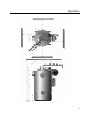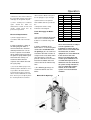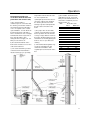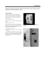
1
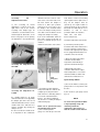
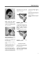
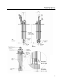
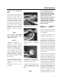
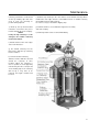
Serial Number: _______________________________
Instruction, Operation,
and Maintenance Manual
Model Number: ___________________________
Contract No.: _______________________________
Date: _______________________________
Fulton Oil Fired/Gas Fired
Hot Water Boilers
4 HP to 150 HP
1
Instruction
This manual is provided as a guide to
the correct operation and maintenance
of your Fulton Oil Fired/Gas Fired Boiler,
and should be permanently available to
the staff responsible for the operation of
the boiler.
These instructions must not be
considered as a complete code of
practice, nor should they replace
existing codes or standards that may be
applicable.
The requirements and instructions
contained in this section generally relate
to the standard Fulton Oil Fired/Gas
Fired Hot Water Boiler. When installing
a packaged unit, this entire section
should be read carefully to ensure that
the installation work is carried out
correctly.
Prior to shipment the following high
standard tests are made to assure the
customer has the highest quality of
manufacturing:
a) Material inspections.
b) Manufacturing process inspections.
c) Welding inspections.
d) Hydrostatic test inspection.
e) Electrical components inspection.
Under no circumstances should weight
be allowed to bear on the jacket, control
panel, or fan housing of any Fulton
Boiler.
The customer should examine the boiler
for any damage, especially the
refractory.
Rigging your boiler into position should
be handled by a experienced in
handling heavy equipment.
f) Operating test.
g) Final Inspection.
We reserve the right to change for
improvement without notice.
h) Crating inspection.
All units can be transported with forklift.
.
2
Content
Section
1
2
Safety Warnings Cautions and Notes
3
Operation
4
Maintenance
5
Parts
Description/Instructions
Specifications & Dimensions 4HP-150 HP
Locating the Boiler
The Fuel Oil Supply
The Gas Supply
Water Supply
Boiler Installation
Electrical Requirements
Fresh Air Supply for Boiler Room
Conventional Venting
Exhaust Side Wall Venting
Combustion Air Intake
Corrosion of Flue Pipe
Installation Checkpoints
Cleaning the Pressure Vessel
Starting the Boiler
Oil Burner Set Up
Gas Burner Set Up
Primary Air Adjustment
Secondary Air Adjustment
Boiler Controls
Cyclic Pump Switch
General
Primary and secondary Air Adjustment
Draft
Transformer
Flame Rod Adjustment
Flame Scanner Adjustment
Oil Supply
Oil Nozzle
Oil valve
Temperature control
Cad Cell
Test for Burner Circuit
Pump Circuit
Check Cyclic Control System
Replace Handholes Gaskets
Clean Burner Assembly
Stainless Steel Combustion Ring
Dirty Flue
Furnace Refractory Replacement Procedure
Trouble shooting
Oil Burner and Ignition Assembly Components
Gas Burner and Ignition Assembly Components
3
Content
Sketch of Layout for Boiler Room
6
Warranty
Files Card for Fulton Boiler Users
Guarantee Card of Fulton Boiler
4
Safety Warnings Cautions &Notes
5
Safety Warnings Cautions &Notes
Safety Warnings, Cautions &
Notes
The following WARNINGS,
CAUTIONS, and NOTES appear in
various chapters of this manual.
They are repeated on these safety
summary pages as an example
and for emphasis.
WARNINGS must be observed to
prevent serious injury or death to
personnel.
CAUTIONS must be observed to
prevent damage or destruction of
equipment or loss of operating
efficiency.
NOTES must be observed to keep
boiler being operated with high
efficiency.
It is the responsibility and duty of all
personnel involved in the operation
and maintenance of this equipment
to fully understand the WARNINGS,
CAUTIONS, and NOTES by which
hazards are to be reduced or
eliminated. Personnel must
become thoroughly familiar with all
aspects of safety and equipment
prior to operation or maintenance
of the equipment.
NOTE
After installation is completed
and prior to operation the
pressure vessel should cleaned.
CAUTION
Do not store halogenated
hydrocarbons near or in the
boiler room.
NOTE
a) The fused disconnect switch
that controls the feed water
pump should be kept in the “on’
position at all times during the
boiler operation as well as
during the non-operating period
of the boiler.
To ensure that your Fulton Hot
Water Boiler is kept operating
b) This switch should be turned
“off” only when repairs or
adjustments should be made.
safely and efficiently, follow the
maintenance procedures set
froth in Section 4 of this manual.
CAUTION
NOTE
Do not tamper with the safety
features of the low water safety
cut off.
NOTE
The flame scanner is located on
the outside edge of the burner
top plate for 20HP-150HP.
NOTE
WARNING
Before the boiler is operating:
a) Check all of the electric
connections in the panel box are
firm.
b) The content of each chapter in
this manual must be understood
first.
NOTE
Check the effect of installation,
including:
a) Requests for electric wire and
voltage.
b) Fresh air supply.
c) Oil or gas line and oil or gas
supply.
CAUTION
When stopping the boiler for any
extensive repairs, shut off main
disconnect switches on both the
boiler side as well as the feed
water side.
The bottom refractory must not
be damaged when the top
refractory is replaced as
necessary
NOTE
Fulton recommends that feed
water treatment should be
performed before it is added into
the boiler.
WARNING
Make sure main power switch is
off before starting work.
NOTE
After a new Fulton Boiler has
been in operation for several
months, pieces of burned metal
will be found in the space at the
bottom of the boiler. These
pieces of metal act as the formed
combustion ring effect during
manufacture. This is a normal
condition and does not affect the
efficiency and the life of the
boiler in any way.
6
Operation
7
Operation
8
Operation
Specifications
Standard Models FBB
4
6
10
15
20
30
40
50
60
80
100
130
150
Boiler HP
4
6
10
15
20
30
40
50
60
80
100
130
150
158
236
399
593
793
1191
1586
1983
2382
3174
3569
4760
5550
4
6
10
15
20
30
40
50
60
80
90
120
140
Ratings (sea level to 914m)*
Output(steam)
1000Btu/Hr
10000Kcal/Hr
Hot water Rating
kg/Hr
1333
2000
3333
5000
6666
10000
13333
16666
20000
25000
30000
40000
46667
Light diesel oil **
kg/h
4.30
6.45
10.76
15.22
20.29
30.44
40.58
50.73
60.88
74.40
89.29
119.05
137..36
3
Ft. /h
2.14
3.21
5.35
7.58
10.10
15.15
20.20
25.25
30.30
37.04
44.44
59.26
68.37
3
Ft. /h
5.41
8.12
13.54
19.15
25.54
38.30
51.07
63.84
76.61
93.63
112.36
149.81
172.86
3
13.77
20.65
34.42
48.70
64.94
97.40
129.87
162.34
194.81
238.10
285.71
385.95
438.46
Propane gas
Natural gas
Town gas
Ft /h
Natural gas boiler
IN
1
1
1
1
1.25
1.5
1.5
1.5***
2
2.5
3
3
3
Connection size
mm
25
25
25
25
32
38
38
38
50
64
76
76
76
GAS OIL
GAS OIL
GAS OIL
GAS OIL
GAS OIL
GAS OIL
GAS OIL
GAS OIL
GAS OIL
4
4
Burner
Motor HP
3450RPM/60CY
2850RPM/50CY
1/3
1/3
1/3
1/3
1
1/3 3/4 1/3 3/4
1 /2 2
1
1
1 /2 2
1 /2 2
2
3
2
3
5
Electric Power Requirements (In Amps)
220V/50CY/1Phase
3.5
3.5
3.5
3.4
5.3
5.3
-
-
-
-
380V/50CY/3Phase
-
-
-
-
-
-
3.7
3.7
3.7
4.6
Control voltage 220V/50CY/1Phase
2
2
2
2
2
2
2
2
2
2
-
-
-
4.6 6.2 6.6
2
2
2
8
8
2
2
Notes:
3
3
**Fuel consumption based on Light oil 11200 kcal/kg, propane gas 22500kcal/ m , Natural gas 8900 kcal/ m , Town gas 3500
3
kcal/ m .
***2 inch IRI and CSA.
We reserve the right to change specifications and /or dimensions for improvement.
9
5
Operation
10
Operation
Dimensions and Weight
Boiler
HP
4
6
10
15
20
30
40+
50
60
80
100
130
150
Minimum Clearance
A. The Front of The Boiler
IN
mm
41
1041
41
1041
41
1041
41
1041
41
1041
41
1041
41
1041
41
1041
41
1041
41
1041
41
1041
41
1041
41
1041
B. Sides & Rear of Boiler
IN
mm
36
915
36
915
36
915
36
915
36
915
36
915
36
915
36
915
36
915
36
915
36
915
36
915
36
915
Clearance Required for
IN
Burner Removal
mm
72
1828
82
2083
86
2184
92
2337
96
2438
106
2692
104
2641
114
2896
124
3150
126
3200
129
3277
151
3835
157
3988
Height and Width
D. Height of Boiler
IN
47
57
63
69
72
82
73.5
87
93
93
99
117
117
mm
1194
1448
1600
1753
1829
2083
1867
2210
2362
2362
2515
2972
2972
E. Boiler Height with Trim IN.
and fuel train assembly
mm
65
1651
75
1905
80.5
2045
86.5
2197
92.5
2350
102
2591
94
2388
106.5
2705
120
3048
122
3099
125
3175
135
3430
141
3582
F. Boiler Diameter
IN
26
26
28
30
39
46
55
55
55
63
68
76
76.5
mm
660
660
710
760
990
1170
1400
1400
1400
1588
1740
1936
1943
G. Overall Depth (Stack
IN
to Burner Fan Housing) mm
44
1118
44
1118
46
1168
47
1194
60
1524
67
1702
73
1854
78
1981
78
1981
90
2280
120
3043
134
3395
136
3455
Boiler connections
H. Hot Water Outlet
IN.
Diameter
I. Return Water Inlet
Diameter
J. Return Water Inlet
Height
K. Return Water Inlet
Length
L. Return Water Inlet
Depth
M. Boiler Blow Off Outlet
Diameter
N. Flue outlet Diameter
1.5
1.5
2
2.5
2.5
3
4
4
4
4
4
5
5
mm
40
40
50
65
65
80
100
100
100
100
100
125
125
IN
mm
1.5
40
1.5
40
2
50
2.5
65
2.5
65
3
80
4
100
4
100
4
100
4
100
4
100
5
125
5
125
IN
15.5
15.5
16
16.25
17.25
17.5
18.75
18.75
18.75
20.16
20.16
23.7
23.7
mm
394
394
406
413
438
443
476
476
476
512
512
603
603
IN
mm
18
457
18
457
19
483
20
508
23
584
26
660
30.5
775
30.5
775
30.5
775
33.5
851
37.5
953
36.8
935
36.8
935
IN
6.25
6.25
7.25
7.88
11.75
14.8
18
18
18
24
27
30
30
mm
159
159
184
200
299
375
457
457
45
610
686
760
760
IN.
1
1
1
1
1.25
1.25
1.5
1.5
15
1.5
1.5
2
2
mm
25
25
25
25
32
32
40
40
40
40
40
50
50
in.
6
6
6
8
10
12
12
12
12
14
14
16
16
mm
152
152
152
203
254
305
305
305
305
356
356
400
407
O. To Center of Flue Outlet in.
mm
42
1070
52
1320
58
1473
63
1600
66
1675
73.5
1867
65
1651
79
2007
85
2159
95
2423
95
2423
107
2723
110
2794
P. Safety Valve Diameter
0.75
0.75
0.75
0.75
1
1
1.25
1.25
1.25
1.5
1.5
2
2
20
20
20
20
25
25
32
32
32
40
40
50
50
14
53
16
61
24
91
39
148
77
292
170
643
220
835
245
927
270
1022
375
1419
580
2195
876
3317
904
3423
LB
1400
1700
2000
2280
3400
4780
6400
6526
7280
10506
11608
15418
15550
KG
640
770
910
1035
1545
2170
2905
2963
3305
4770
5270
7000
7060
IN
mm
Water Content
U.S.GAL
LITERS
Weight
Approx. Shipping Weight
Note:
1.
Input foreign original boiler feed water pipe: connect with screw; the civil assembly ones are all flanged.
2.
There is a spare safety valve connection for 40-150HPboilers.
3.
We reserve the right to change the specifications and dimensions for improving our products.
11
Operation
Locating the Boiler
a) The boiler should be located in
dry surroundings on a level base,
making sure that there is sufficient
room around the boiler to enable the
operator and/or the maintenance
engineer to gain access to all parts
of the boiler. Check location for ease
of water supply and electrical
connections.
b) Place the boiler on a
noncombustible floor with clearances
to unprotected combustible materials,
including plaster or combustible
supports.
c) It is necessary to have the
sufficient clearance from the boiler to
the oil tank for oil fired boiler.
The Fuel Oil Supply
a) Be sure that the oil supply lines
from the tank to the burner are of
proper size. Vacuum should not
exceed 10” of mercury at the oil
pump inlet (including pipe line etc.
total resistance). It is suitable that the
height of pump inlet is 500mm higher
than oil tank outlet when install.
b) All Fulton oil burners are of the two
pass design system requiring a return
line and supply line. The oil pump is
factory set at 230 psi (=16 Kg/cm2).
Do not change this setting without
allowance of Fulton Boiler..
c) A stop valve, a check valve, and an
oil filter must be installed in the oil
supply line.(The filter set position
must be capable of draining gas in
filter and pipe line completely.)
d) When one oil line is feeding two
burners, a check valve ( low
resistance) must be installed in each
unit.
e) Make sure there are no loose
fittings. Loose fittings in the fuel oil
line will allow air to enter into the fuel
line and cause improper firing.
The Gas Supply
a) Gas piping should be installed in
accordance with National Fuel Gas
Code, and any other local codes
which may apply.
b) Install a dirt trap and sink blow off
outlet ahead of all the gas valves.
c) The pipe and the fittings used must
be new and free of dirt or other
deposits.
d) The piping must be of the proper
size to ensure adequate gas supply
to the gas head assembly. Consult
your gas company for specific
recommendations.
e) For natural gas a pressure of 7” to
11” (178mm to 279mm) of water
column pressure at the gas train is
required with burner firing. Do not
exceed 13” of water column.
f) For propane or butane gas the
pressure required is 11”(279mm) of
water column pressure. Again, do not
exceed 13” of water column.
g) When making gas piping joints,
use a compound to seal the gas line
treads. Do not use Teflon tape on gas
line threads.
h) The main and the pilot gas
pressure regulators must be vented
to the atmosphere.
i) After gas piping is completed
carefully check all piping connections,
for gas leaks. Use a soap and water
solution.
Caution
Some matters used for leak testing
are corrosive to certain types of
metals. Rinse all piping thoroughly
with clean water after leak check
has been completed.
j) The boiler must be disconnected at
the boiler shut off valve from the gas
supply piping system when intake
gas pressure is in excess of
14”W.C.
k) The boiler must be isolated from
the gas supply piping system by
closing the shutoff cock during any
pressure testing of the gas supply
piping system at pressure equal to or
less than 1/2 PSIG-14”W.C.
Water Supply
NOTE
Feedwater will affect the life of
the boiler, it is recommended that
suitable water treatment should
be considered before the boiler
is installed (including scale or
oxygen corrosion), for the
damage caused by water is
not covered in the warranty.
Boiler Installation
Read carefully this manual before
installation,
see
installation,
adjustment assistant documents,
and referenced sketch layout of
boiler
room
enclosed
in
“components” tables.
a) Connect return tube with feed
water inlet at the back of boiler, fit
hot water stop valve between boiler
and equipment. Use pipe line to joint
hot water outlet with equipment
requiring water. If cool water system
is installed, the hot water inlet must
be connected with cool water
system and return water.
b) Connect the safety valve to outlet
at left side of the boiler through pipe,
from safety valve pipe to safety
drain point.
c) Do not change water temperature
pressure gauge assembly at any
time.
d) the blow off valve must be
12
Operation
connected to the lowest outlet at
the rear bottom of boiler, from valve
outlet pipe to safety blow off point.
e) There should preset sufficient
space around the boiler for
maintenance to blow off vale and
electric control panel box by
professional personnel.
Electrical Requirements
a) Power supply must be in
accordance with section 5 “Parts”
table .
b) Connect wiring as shown in
the wiring diagram which is
furnished inside the electrical
control panel box. Be sure to
install a separate fused switch
for fan motor and cycle pump. If
the power of pump motor equal
to or more than 3/4 hp, it is
recommended to install a
separate start switch ahead of
the cycle pump.
c) Use fused switch of proper size,
and the position should be as close
as possible to the boiler, the fire
prevention and control code and
others must be fulfilled at the same
time. There is preset a tip for joint in
the electric panel box, but hole is
still need to be drilled on the panel
box for pilot pipe to pass through.
d) Connections for an optional :
220v audible alarm are provided in
the
control panel and are clearly
indicated on the diagram.
Fresh Air Supply for Boiler
Room
a) It is most important to provide
free access of air to the boiler.
6.4cm2 is needed for every 756
Kcal).
b) Proper ventilation of the
boiler room is essential for good
combustion. Install two fresh
air openings, one at a low level
of 610mm from floor and one at
a higher level on the boiler room
(See the picture). This will
provide a flow of fresh air intake
into from the bottom hole and
exhaust the hot air from the top
hole.
c) The following openings are
recommended for each size
boiler:
Make UP Air Openings
BHP
4
6
9.5
15
20
30
40
50
60
80
100
130
150
BT²
1
1
1
4
4
5
5
5
7.5
12.5
16
20
23.5
NOTE
M²
0.09
0.09
0.09
0.37
0.37
0.46
0.46
0.46
0.69
1.11
1.49
1.86
2.19
These measurements are subject
to local regulations. The
installation of exhaust fans in a
boiler room is not recommended.
An exhaust fan, or similar
equipment can create down draft
in the stack or restrict the
burner’s air supply which will
result in poor combustion. It is
essential that only fresh air is
allowed to enter the combustion
air system. Foreign substances,
such as combustible volatiles
and lint, in the combustion
system can create hazardous
condition
。
13
Operation
Conventional Venting (in
accordance with the local fire
prevention and control code)
a) The stack should rise
continuously to the connection with
the chimney, and should contain no
more than two bends at 45 angles
or less. If required as the result of
space limitations, one 90 elbow can
be fitted at the back of the boiler.
There should be two feet of straight,
horizontal flue before any bends or
turns. Any alternative stack
arrangement must supply -.02 -.04”
W.C. pressure burner off.
b) The total horizontal run of the
boiler stack should not exceed 70%
of the total vertical rise.
c). The stack and chimney must be
constructed from material that is
rated for 532 degrees C operating
temperature. Check all local codes
for exact requirements.
d) Adequate provision must be made for the support of the weight of
the chimney and stack to avoid
having too great a load imparted to
the flue outlet connection of the
boiler.
e) The proper flue size and draft
control is most important for proper
burner operation. The flue must be
as large or larger than the outlet on
the boiler. Avoid flue piping too long
and elbows too much by placing the
boiler as close as possible to the
chimney.
f) A mechanical draft regulator may
need to be installed in the flue
outlet. Do not install the draft
regulator prior to the first turn of the
flue.
g) The installer should check the
draft with a meter at -0.02 -0.04”
W.C. pressure with the burner off,
and -0.04 to -0.06 W.C. pressure
with the burner on.
BHP
Boiler Flue Size
Inches
Millimeters
4
6
152
6
6
152
9.5
6
152
10
6
152
15
8
203
20
10
254
30
12
305
40
12
305
50
12
305
60
12
305
80
14
356
100
14
356
130
16
400
150
16
400
14
Operation
Exhaust Side Wall Venting (In
accordance with the local fire
prevention and control code)
Boilers for which sidewall venting
may be utilized are oil, , natural gas,
or gas/oil, sizes 4 to 30HP.The
following criteria is required for
installations using sidewall venting.
1) Flue vent piping shall be pitched
upward at 1/4" per foot of length.
2) A U.L. approved draft fan must
be installed to provide sufficient
draft to safely vent the products of
combustion.
3) The draft fan should be located
as close to the flue outlet as
possible.
4) Draft regulation sufficient to
lower the draft to between -0.02
to -0.04 " W.C. pressure may be
required. The draft regulator(s)
must be between the boiler and
draft fan.
5) The draft fan shall have an air
flow proving switch wired in series
with the boiler air safety switch.
6) The sidewall venting total length
from boiler exhaust to termination
shall not exceed 35 feet (10.7 m)
with 4 elbows maximum.
15
Operation
Combustion Air Intake (In
accordance with the local fire
prevention and control code )
This shall be applicable only for
gas fired vertical units, sizes
4-30 boiler horsepower. The
following criteria are required for
installations using combustion
air intake assemblies.
1) Outside air intake inlet shall
be equipped with a vent cap in
order to prevent flame blow out
from excessive wind. This vent
cap shall have a minimum cross
sectional opening equal to an 8
inch vent pipe.
2) All intake ducting shall have a
cross sectional area equal to or
greater than 50 square inches.
3) A mesh screen shall be
affixed to the air inlet with
openings of approximately 1/2"
x 3/4".
4) The total length from
outdoors to the boiler intake
shall not exceed 35 feet (10.7 m)
with four elbows maximum.
combustion system flue line
increases in temperature, the water
vapor no longer condenses
because the flue temperature is
above the dew point of the
combustion gas. The combustion
gas then dries out (dehydrates) the
hydrochloric acid solution leaving
behind dry chloride salt.
b) When the next cold start-up
occurs, the process repeats except
that more and more chloride
collects and concentrates along the
flue. As the quantity of chloride
increases it does not dehydrate
completely as the flue heats up and
a corrosive poultice develops which
attacks the steel and will also attack
the boiler.
c) Concentration levels of only a
few ppm of chlorine containing
compounds in combustion air can
produce serious corrosion over
long periods of time. High chlorine
containing compounds such as
carbon tetrachloride or perchloride
would be prime suspects.
a) After the boiler has been
installed and before it is placed in
service it is advisable to purge the
pressure vessel of any oil film, dirt,
or other impurities. Clean the
pressure vessel as follows:
1) Isolate the boiler from the system
by shutting off the water outlet
valve.
2) Remove the safety valve.
3) Mix washing soda with water r
and pour it into the boiler through
the safety valve opening.
4) The mixture of washing soda to
water is as follows:
Boiler Size
Soda
4-6
10-15
20-30
1lb(454g)
2lb(908g)
3lb(1362g)
40-50
60
3-1/2ib(1589g)
4lb(1816g)
80
100-130
5lb(2270g)
7lb(3178g)
150
4250g
Installation Check Points
Corrosion of flue pipe
a) In the case of a combustion flue
pipe, acid may develop over a long
period of time per the following
process. Chlorine containing gases,
such as halocarbon refrigerants,
carbon tetrachloride,
trichloroethylene, when drawn into
combustion air are broken down
into elemental chlorine gas which
exits up the flue pipe. If the flue
pipe is cold, as it would be if the
combustion process had been off
for some time, the water vapor
condenses in the flue pipe during
the first few minutes of ignition and
the chlorine in the combustion gas
dissolves in the water forming
hydrochloric acid. As the
1) Make sure all piping connections
are complete and tight.
2) Make sure the temperature
controls are adjusted properly.
3) Make sure all electrical
connections in the control panel
box, the low water probe, and
elsewhere are secure.
4) Make sure the door in the boiler
room is closed. Combustion air
contaminates can cause damage to
the boiler jacket and stack.
NOTE
After installation is complete and
prior to operation the pressure
vessel should be cleaned.
Cleaning the Pressure Vessel
5) Replace the safety valve.
6) Fill the boiler with water until the
low water relay close. If water has
been flowing from the drain valve ,
press the electric panel box reset
button.
7) Shut off the boiler when
temperature reaches 80 degree of C.
Allow this hot solution to remain in
the boiler for 10 minutes.
8) Drain and flush the boiler twice
with fresh water.
9) To remove all the oil and dirt
from cycle pipe line and heat
exchanged equipment, cyclic clean
by add suitable soda should be
considered as well.
16
Operation
CAUTION
Before start the boiler:
a) Check if all the wiring of
circuit in electric panel box for
the boiler are fixed.
Do not store halogenated
hydrocarbons near or in the
boiler room.
In general, ensure that the boiler
area is in conformance with
established boiler room
requirements. Review local
codes.
As a final checkpoint, again,
water treatment.
Here we emphasize the
importance of proper water
treatment. Water analysis should
be made by a competent water
treatment concern and their
recommendations should be
followed.
b) Be sure that the operating
person have read all the chapter
s in this manual and understand
completely.
Boiler Accessories
2) Remove the safety valve
The following accessories are
supplied when output: ( some
may be pre-fit )
Item
Quantity
Temperature
1
Pressure Gauge
Low Water Probe
1
Safety Valve
1
Operation
1
Temperature
Control
Limit
1
Temperature
Control
3) Inject soda water
Blow Off Valve
1
WARNING
1) Shutting off the water outlet
valve
17
Operation
18
Operation
The follows are operation instructions for Fulton hot water boilers. If user do not operate as these
instructions, we reserve the right to not cover it.
Starting the Boiler
Stop! Make sure you have read any followed all
previous safety information. Carry out the following
procedure on the initial start up of the boiler and on
every subsequent occasion when restarting the boiler
after a shut down.
1). Open the return water valve.
2) Open stop valve on top of the boiler.(supply hot water
system)
3) Open makeup water valve.
4) Fill in water into boiler and system.(During filling, the
overflow valve must be fully open to exhaust all the air.
When water flows out from the overflow valve, the boiler
and system must be filled completely.)
Place feedwater pump fused switch in the “on”
position.
5) Shut off main power switch.
6) the IDIDO will be activated. Press the reset button as
necessary.
7) The IDIDO will be activated when the boiler is filled
with water, the low water relay then shut automatically.8)
If for any reason ,water level separates from the low
water probe, boiler will shut off automatically and start
alarm (if fitted).
19
Operation
Oil Burner Set Up
a) Open the oil line shut off valves.
b) Switch on the main power to the burner.
Depress the manual reset button on the
panel box.
c) To start the burner, turn on the switch
located on the panel box. The blower
motor will now start to deliver the air into
the furnace. After the blower starts about
7 to 30 seconds, the magnetic oil valve is
energized allowing the oil pump to deliver
fuel to the furnace where it is ignited.
15-60HP Fuel Oil/ Gas MEC230 series Control
panel
d) On Fulton 4-15HP oil fired boilers, the
burner control sights the fire from a
cadmium sulfide photocell located on top
of the burner. If it does not detect the
flame in approximately 15 seconds, it will
go out on safety lockout and shut down
the burner.
e) On Fulton 20-150 HP oil fired boilers,
the flame safeguard control sights the fire
from an ultraviolet scanner located on top
of the burner. There will be a first stage
pilot before the main oil valve is energized.
After flame is proven the main oil valve
will come on. If flame is not proven, it
goes into safety shut down.
15-60HP Fuel Oil Siemens series Control panel
Note:
4-20 BHP have only one stage. 30-150
BHP have two.
f) Reset by depressing the button on the
flame safeguard control. If boiler does not
respond after 3 attempts, contact your
authorized Fulton Representative.
g) The main air control shutter is adjacent
to the oil pump and should be adjusted so
as to give a clean burning fire without
excess air being delivered to the burner.
h) The secondary air control is an L type
handle located on the top of the burner
scroll which controls the amount of the air
that is delivered over the oil nozzle. This
should be adjusted to keep the fire from
backing up into the blast tube.
i) Make sure the secondary air damper
is locked after adjustment.
j) Lock into position the main air control
shutter.
k) After the oil has been ignited in the
burner, it will be controlled through the
temperature control in the panel box
which should be adjusted to suit the boiler
application.
15-60HP Fuel gas Siemens series Control panel
80-150HP Fuel Oil(Left) Gas(Right) Siemens
series Control panel
20
Operation
Gas Burner Set Up
a) Open the manual gas cocks on
the pilot and main lines of the gas
head.
b) Switch on the main power to the
burner. The water level relay is
equipped with a manual reset.
Depress the button on the box.
programmer control will open the
contacts and shut off the burner.
Push the reset button on the control
to reset. If trouble persists, it may
be necessary to check the flame
rod setting or the UV scanner. See
Maintenance
Section
4
for
procedure to check flame rod
setting or UV Scanner.
c) The flame programmer is the
main control in the panel box. The
programmer in conjunction with a
sensing device, either a flame rod
or a UV scanner, "supervises" the
ignition sequence - proves the
flame is satisfactory, and finally
"monitors" the established flame.
Should any fault occur, either
during the ignition sequence or
during
normal
running,
the
programmer will immediately go to
"lock-out" and the burner will shut
down.
d) When the pilot flame is
established, the flame rod (or
ultra-violet scanner) senses the
voltage which is created in the
flame between the flame rod and
the gas nozzle. This signal is
transmitted back to the flame
programmer which opens the main
gas valve giving a main flame.
UV Scanner fit with 20-150HP
Boilers
Primary Air Adjustment for
Fulton Gas Fired Boilers
a) The primary air adjustment or
main air control is located at the fan
housing face. This control is used
to supply the burner with excess air
needed to facilitate good
combustion. Too much or too little
air will result in poor combustion. It
is important to make sure the
lowest level of excess oxygen is
present while still maintaining a
high level of carbon dioxide and
negligible carbon monoxide. Using
a CO2 or O2tester it is possible to
determine the percent of excess air
in the combustion mixture.
b) On a No.2 oil fired boiler the
excess oxygen should be 4 percent
with 11 percent carbon dioxide. A
smoke test is the best means to
check for combustibles in the flue
gases. A smoke test of 0-2 is an
acceptable level. It is best to
measure the flue gas with the stack
in excess of 216 degree of C. To
increase the oxygen in the burner
open the air adjustment to the right.
To close or reduce the oxygen in
the burner , move it to the left.
e) Fulton 4 - 30 HP. natural gas
fired boilers can be equipped with
flame rods or UV scanners.
f) All Fulton propane or butane
boilers and more than 50HP Fulton
natural gas boilers are standard
furnished with UV Scanners.
If the installation is new or the
burner has been disassembled, the
burner may not fire at the first
attempt due to air which must be
purged from the gas lines. This will
result in the burner flame
programmer going to lockout.
Repeat the procedure for starting
the burner. The main gas valve will
remain open as long as there is a
demand for heat and the flame is
carrying a sufficient signal to the
flame programmer.
Flame rod fit with 4-30HP Boiler
Primary Air Adjustment is
located at the fan housing face.
If the flame is not established at the
start, the safety switch in the flame
21
Operation
Secondary
Air
Adjustment Procedure
a) The secondary air control
adjustment is located on the top,
right hand side of the burner
assembly. This damper type air
controller is used to introduce air to
and through the blast tube of the
burner. The purpose of the primary
air adjustment is to proportionately
divide the air to the center or outer
and center of the blast tube area.
On most boilers the damper is
locked in a wide open position.
However, if it is necessary to close
the damper, care should be taken
to close the damper slowly and no
more than 1/4 of the distance of the
swing of the damper assembly.
b) A visual examination down the
blast tube should reveal that no
process to maintain proper air fire
chamber.
mixtures between the outer surface
heat, flames or fumes are backing
up through the burner plate area. If
they are the damper must be
opened up once again. Failure to
remove the flame or gases from the
blast tube area will result in severe
backfires as well as cause
premature failure of electrodes,
flame rods, and other
burner components.
hot water temperature of the boiler.
b) Low water protective probe-Cut off the units when water level is
too low. Low water control relay is
located on the right top in the panel
box. If equipped with manual reset
controller, it must be shut off.
c) Boiler operation temperature
controller—Control water
temperature automatically to
operate at determined ranges
Secondary Air Adjustment for
40-150HP
d) Boiler limit temperature
controller—When boiler output
water temperature is exceed the
determined data, the boiler shut
down and need manual reset.
Cyclic Pump Switch
Secondary Air Adjustment for
4-30HP
fire chamber with less air going
down the blast tube area. By pulling
the damper open more air is forced
down the blast tube and less on the
outside wall of the deflector face
and fire chamber. By moving the
damper closed,
the air is forced to the outside of the
It is important in the combustion
c)A visual inspection down the
view port should also show the fire
completely covering the furnace
walls. If the fire is tunneling down or
is not to the outside wall of the
furnace , the efficiency will drop
off .Close the secondary air damper
until tunneling stop.
Boiler can be operated and has
the following auto-control
a) Pressure/temperature
gauge—To show the pressure and
a) The fused switch to control cyclic
pump must be in off position at all
the time.
b) the circuit for cyclic pump is laid
by user.
NOTE
To ensure that your Fulton Boiler
is kept operating safety and
efficiently, follow the
maintenance procedures set
forth in section 4 of this manual.
22
Maintenance
23
Maintenance
24
Maintenance
Prior to the commencement of any work requiring the removal of cover plates and the opening of control
panel box, the electrical supply must be disconnected.
The General
a) Keep boiler clean outside and
inside with no dirt deposited.
b) Check power and circuit wiring
tightness periodically.
c) Take annual examination by
competent professional person.
d) Fit with water treatment as
necessary.
e) Check temperature pressure
gauge periodically to ensure it is in
accordance with temperature
controller.
Primary and secondary
adjustment-oil and gas
air
a)The secondary air control
adjustment is located on the top,
right hand side of the burner
assembly. This damper type air
controller is used to introduce air to
and through the blast tube of the
burner. The purpose of the primary
air adjustment is to proportionately
divide the air to the center or outer
fire chamber.
By moving the damper closed,
the air is forced to the outside of the
fire chamber with less air going
down the blast tube area. By pulling
the damper open more air is forced
down the blast tube and less on the
outside wall of the deflector face
and fire chamber.
b) It is important in the combustion
process to maintain proper air
mixtures between the outer surface
and center of the blast
tube area. On most boilers
the damper is locked in a
wide
open
position.
However, if it is necessary
to close the damper, care
should be taken to close
the damper slowly and no
more than 1/4 of the distance of the
swing of the damper assembly.
c) A visual examination down the
blast tube should reveal that no
heat, flames or fumes are backing
up through the burner plate area. If
they are the damper must be
opened up once again. Failure to
remove the flame or gases from the
blast tube area will result in severe
backfires as well as cause
premature failure of electrodes,
flame rods, and other burner
components.
d) A visual inspection down the
view port should also show the fire
completely covering the furnace
walls. If the fire is tunneling down or
is not to the outside wall of the
furnace , the efficiency will drop
off .Close the secondary air damper
until tunneling stop.
e) I t is very important for all the oil
and gas fired boilers to take care of
the adjustment of the secondary air.
Observe the blast tube and furnace
area if adjust the secondary air
adjustment as necessary.
f) the flame should cover the
furnace wall and no flame in the
blast tube area, to improve boiler
combustion and solve smoke rising
from oil boiler by adjustment to this
controller.
25
Maintenance
Draft—Oil and Gas
a) Draft is the resistance exhausted
by chimney when transfer air into
heat equipment in combustion,
covering the furnace flame. It is
very important for the design and
height of flue because the vent
stabes at different value. It would
be wrong considered that the
design is fine and the high
efficiency system is in trouble. The
standard vent should be
-0.02-0.04W.C.
when the chimney temperature is
205 degrees of C. the vent
pressure should be in -0.05 to 0.07’’
W.C.
b) If the vacuum is too more, then:
1. Decrease the efficiency.
2. Poor combustion.
3. Boom sound in combustion.
4. Rising the temperature of
chimney.
c) If the vacuum is too little, then:
1. Delay the gas in the flue, with
corrosion remained.
2. Poor combustion and black
smoke.
3. Ash collected in flue.
fan with the allowance of the
manufactory. The positive pressure
will make the flame being blow out
or backfire.
Transformer-Oil and Gas
a) Be careful during check the
transformer, because it can create
high voltage as 10000V.If the
transformer can not supply ignite
signal when testing the circuit, it
shows the transformer is damaged
and need to be replaced.
NOTE: Usually transformer can
not ignite is because the
regulation to control relay or
ignition electrode, Take care of
checking these areas before
replacing.
b) Oil valve is connected by
transformer in most oil fired boilers.
c)Check the primary coil of
transformer and wiring, and if
output wire is nor
Flame Rod (Gas)
d) It is the most simple and feasible
method that use gas parameter to
regulate vent. In some condition
(vacuum is too little) ,install a draft
The flame rod adjustment is made
by loosening the lock nut and
turning the porcelain portion of the
flame rod clockwise or counter
clockwise. Whenever a flame rod is
moved, care should be taken to
ensure that the flame rod does not
ground out by touching the metal
surface of the blast tube assembly.
A microammeter can be used to
determine proper signal response.
The pilot flame signal should be 1
to 2 VA to activate the main gas
valve. The main flame should be
adjusted to 3.5 to 5 VA to ensure
continued performance. A poor or
unsteady signal will going off the
boiler flame programmer controller
safety..
b) If the boiler has two flame rods,
adjust the flame rod in the burner
plate first, with the outside one
disconnected. After a good pilot
signal is established on the inside
flame rod, then the outside flame
rod can be hooked up and the
signal
adjusted
for
proper
responses.
c)If the inside flame rod contacts
with the metal, the microammeter
would show a negative data and
not to zero. If a signal is erratic after
adjusting the flame, the main and
26
Maintenance
secondary air supplies may need
adjusting. If a air flame rod is
cracked or broken, the porcelain
will have to be replaced to get a
proper signal. This flame rod can
only be used with control amplifier
with flame response correction
Flame Scanner Adjustments
for Fulton Gas/Oil Fired
Steam Boilers
a) Flame scanner adjustments are
made with the detectors installed
and the burner running. It is
essential to obtain optimum flame
signal detection for safe and
continual
operation
of
the
programmer control.
b) Small scanners are used in more
gas fired boilers to detect violet
flame signal. Because scanner
collects the signal in this
frequency band, to ensure no
interfere signal occur around the
scanner, It is the ignition interfere
that the scanner take it as pulse
signal by mistaken because the
wrong adjustment of ignition rod or
other types result.
c) To ensure the scanner do not
receive this signal by testing,
shutting off all of the gas switch on
gas head. Insert the microammter
needle into the amplifier output,
start the boiler, read the
microammter
during
the
procedure of ignition testing. If the
data is more than 1VA at that time,
then take it as ignition interferes.
The scanner should be realigned
to obtain data less than 1VA,
which may need to put a small
diameter orifice in to the area of
scanner
d) Open the gas valve in secure
and adjust scanner to get the
biggest capable value as soon as
no flame interfere is tested.
e) All of the oil fired boilers use
violet sensor scanner or cad cell.
The ignition testing must be
performed whatever scanned is
inoperable. For oil fired boilers,
disconnect the control wire with oil
valve, then test the same as gas
fired boilers.
f) Use light test to examine its work
if the scanner may be damaged.
Light when flame signal occur, if
the scanner works as normal, then
it shows that good signal can be
obtained only by aligning the
scanner. Be sure that do not light
when no flame is required,
otherwise the control relay would
shut off.
2. Oil line is damaged or leak.
3. Oil pipe connection is loosed.
4. The low resistance check valve
is leak.
b) the intake line should be full of oil
at any time, no air ,no gas lock. The
standard Fulton boiler pump
2
pressure is 230PSI( 16.1kg/cm )/
Oil Nozzle
g) If it is verified that the scanner is
damaged, then it must be
replaced. No dirt and deposits
collected on the light eye surface
h) the system required 1-2VA signal
can be intake to main flame
procedure, then get the biggest
signal at the main flame period.
i) To establish good ignition , it may
be adjusted as follows:
1. Main/secondary air adjustment
2. Increase or decrease light area
of scanner
3. Realign scanner
4. Realignment of ignition electrode
5. Increase pilot gas during ignition
6. Increase a little the orifice size
7. Realign flame rod without
scanner
j) Do not make any adjustment to
signal response without scanner.
a) Here is strict request for oil
nozzle of Fulton boilers. If need to
replace, use the one supplied by
Fulton company.
b) Most of the Fulton boilers are
2. I
It will
working at 16.1kg/cm
change the combustion condition
in boiler and system efficiency by
increase or decrease the pump
pressure. So, it is recommended
that do not change pump pressure
without allowance of Fulton
company.
c) Replace the oil nozzle if it is
damaged. Remove burner plate
assembly, wrench nozzle with new
moon type, fit the same type
nozzle and refit burner plate
assembly. Be sure not to damage
the ignition electrode.
Oil Valve
Oil Supply
a) Be sure that the oil supply line
are of the proper size. Do not use
any pipe with size. The old or
damaged ones should be replaced
at once to avoid the damage
increased. Check pump supply,
pump pressure and vacuum to
show the efficiency of fuel oil
supply system. The suitable pump
vacuum should be 8-10’’of mercy.
If vacuum is too high, may be the
follows in trouble:
1. oil line size, oil line is blocked.
2. Oil line is too long.
3. Too low for locating the oil tank.
a) Most of the Fulton boiler s use W
screw pipe electric magnetic valve.
The main problem may be occurred
is stick at pre-ignition or after
ignition. Check oil valve, disconnect
the copper pipe joint with nozzle
assembly, collect the more or
leakage oil with a tank, push into
motor starter with the boiler
switch is on, and if oil dip from oil
valve, the oil valve must be cleaned
or replaced. Oil valve can not leak,
be sure instead with the same type
and same coil voltage valve. Use
small sleeve wrench and new moon
type can remove the valve quickly.
Remove screw pipe with
screwdriver, hook up the nut on the
screw pipe valve.
4. Oil filter is too dirty.
If no oil come into pump, check:
1. Pump is not in good sealing.
27
Maintenance
Temperature Controller
Cad Cell
control). If use low temperature
controller, the circuit would come
from working temperate.
a)
the water pump
supplied by user.
circuit
is
Check Cyclic Control System
See
‘maintenance’
section
flame .scanner adjustment and
components.
Test for burner circuit
a) Power is connected to H(live
wire) and N ( neutral wire)
terminal board. it will supply power
for low water safety relay, LWSR
terminal 1,3, the current arrives
fan motor through burner motor
start and M terminal on terminal
board.
b) LWSR is connected with low
water probe and ground, forming a
circuit to activate #10 foot on
LWSR. The current travels to
terminal #10 on terminal board
after leaving #10 foot.
c) The circuit continue pass through
the upper limit temperature control
(limit control) , then get burner
switch at working temperature
control ( constant temperature
d) After the circuit test signal normal
by programmer controller, the
current continue go to terminal T1
on terminal board, then TI activate
relay. Then circuit connect air
switch, the ignition transformer and
pilot gas valve or pilot oil
valve( determined by boiler type)by
acceptance of relay,
a) Drain out water tank, use tap
washing, check float valve working.
b) heck if the electric control and
motor is normal.
c) Check cyclic pump, oil pump.
d) Shut down boiler and drain boiler
water.
Note
1. All the indication lamp power is
supplied by control relay.
2. Manual reset switch is powered
by LWSR.
3. the shut off switch of circuit and
high-low gas pressure switch are
powered by terminal board.
f) Remove the handholes and
inspect the interior of the vessel
for scale or sludge deposits. The
amount of deposits will indicate
the efficiency of the water
treatment,. The frequency of the
inspection will depend on the
condition of the water side of the
boiler.
4. Fuel option relay is powered by
control relay and terminal board.
Pump circuit
28
Maintenance
hand tight and then snug with
wrench about 1.4 turn. Do not
compress excessively.
3) Check the combustion efficiency
of the burner and adjust if
necessary.
4) Clean probe, There must be no
pressure on the boiler during the
removal of probes.
5) Check refractories for soot or
breakage and inspect the stainless
steel ring.
Inspect hand holes for scale or
sludge build up
Replace hand holes gaskets
using the following procedures:
1) Remove the hand hole assembly
using a 1-1/4’’ tee handle wrench or
drive socket wrench.
Illustration
shows
pressure on gasket
correct
c) If the gasket leaks while pressure
is being built up, tighten only
enough to stop leakage. Never
tighten more than necessary to
prevent
leakage.
Excessive
tightening may shorten the life of
the gasket.
d) Refill the boiler with fresh water.
Removing hand holes assembly
with a Tee Handle Wrench
2) Remove the old gasket and
thoroughly clean the surface on the
boiler and the plate.
Illustration
shows
compressed gasket
over
3) Fit the hand hole assembly as
follows:
Clean Burner Assembly
a) Place the gasket on the hand
hole plate and ensure that it is
seating correctly. Do not use any
grease, lubricant, or adhesive.
b) Position the plate in the boiler.
Set the yoke and tighten the
securing nut sufficiently enough to
provide a snug fit. Verify theposition
of the plate in the boilerthen make it
1) Clean fan blades; oil the motor.
Replace the fuel oil filter and clean
the oil pump strainer.
2) Remove, clean and adjust the oil
nozzle and the electrode assembly.
Make sure the settings correspond
to those in the illusion.
29
Maintenance
1/4’’
( 1/16’’)
±
1/4’’
( 1/16’’)
±
Gap to Pipe
3/16’’(4.8mm)
( 1/16’’,1.6mm)
±
Gap to Pipe
3/16’’(4.8mm)
( 1/16’’,1.6mm)
±
30
Maintenance
Stainless Steel Combustion
Ring
a) The stainless steel combustion
ring in Fulton gas fired boilers are
designed to bring quick and
effective flame transfer to the flame
wall. The ring should fit securely
and against the furnace wall for
best results. This will reduce the
gas flow behind the stainless ring
and
accept
more
complete
combustion. First remove burner
assembly and then pull it out
directly to remove the stainless
ring.
.
After a new Fulton Boiler has
been in operation for several
months, pieces of burned metal
will be found in the space at the
bottom of the boiler. These
pieces of metal act as the formed
combustion ring effect during
manufacture. This is a normal
condition and does not affect the
efficiency and the life of the
boiler in any way.
2) Wire brush flue passage
Furnace
Replacement
a).Remove the burner plate and top
plate assembly up and out of the
scroll assembly.
NOTE
It is not fitted for 80HP, 100HP,
130HP, 150HP boilers which
apply high low burner.
b) Remove the stainless steel
combustion ring from the furnace.
Dirty Flues
a) Dirty flue can cause air flow
restriction s resulting in poor
combustion and loss of efficiency.
Check the temperature in flues to
determine if the dirty in flues is
serious. If the flue temperature is
exceed 315 degrees of C, the flue
may be too dirty or other air flow
restriction exist. Test in flue apart
from the boiler within 1 foot with a
flue temperature equipment. Clean
flues as follows:
b) usually clean deposits one time a
year unless the setting of burner is
disturbed and more deposits
created.
1) Remove the burner and flue
cover plate.
Refractory
Procedure
3) Remove clean out plugs and
clean the bottom of combustion
chamber.
4) Remove all soot from the top,
and from the clean out plugs at the
bottom with a vacuum cleaner.
5) Replace clean out plugs carefully
so as not to damage insulation and
replace burner and flue cover
plates.
NOTE
c) Remove the clean-out plugs from
the bottom sides of the boiler. 4-15
HP boilers have one clean out plug
located at the panel box.20-60 HP
boilers have one clean out plug
located at the bottom of the boiler
to the right side of the panel box.
80-150 HP boilers have two clean
out plugs located at the bottom of
the boiler to the left and right sided
of the panel box.
d) Break off the top holding clips
that were to keep the refractory in
position during shipping. The 4-50
HP boilers also have holding clips
beneath the top refractory. There
is no need to cut the holding clips
located beneath the top refractory
as the refractory may be rotated
90º during installation of the lower
refractory. The 60 HP boilers have
welded flats bars beneath the top
refractory. These bars will have to
be cut to change the lower
refractory and refitted as the top
refractory is installed. For the lower
31
Maintenance
refractory you will also need to break
off the top holding clips that were
used to keep the refractory in
position during shipment.
i) Install the top refractory in the same manner as the bottom refractory. When
installed the outer edges must be sealed with insulcrete -a castable refractory
mix available from the Fulton factory.
It is not necessary to reinstall the shipping clips.
e) Break up the top and/or bottom
refractories and remove the pieces
from the through the clean-out plugs.
NOTE
If only the top refractory is to be
changed, the bottom refractory
need not be broken.
j) Install the stainless steel combustion ring, burner assembly
and clean out plug.
k) Normal operation can be resumed immediately.
f) Round and bevel the outer edges
of the new refractories.
g) The bottom refractory has the
largest hole, while the top refractory
has the smallest.
h) Lower the bottom refractory
down the furnace with wire fastened
around the refractory in three
positions. When the refractory is
close to position, it can be tipped by
maneuvering the wire to drop it flat
on the holding clips. If the refractory
will not tip, it may have to be
removed and again rounded and
beveled.
32
Maintenance
NOTE: When shut down the boiler for repairing, shut off main power switch and disconnect main
fused switch of boiler and water supply system.
Trouble shooting
The following list the troubles may be occurred in Fulton oil and /or gas fired boilers:
The following trouble shooting guide will assist in the diagnosis and the correction of minor field problems . It contains
instructions and information and isolates possible troubles which occur during normal operation. It should be used in
conjunction with the wiring diagram.
Troubleshooting for steam boilers
Problem
Ignition Failure
Cause
Remedy
1. Power Supply
check fuse or circuit breaker. Reset or replace, as
necessary.
2.Ignition Electrodes
Check electrodes for carbon built up and clean if
necessary.
Check for proper adjustment as section 2.
Check for cracks in porcelain. If found, replace.
Check voltage between transformer leads at terminal
block to be sure transformer is being powered.
3. Transformer
4. Cad Cell
5.Dirt on Flame Scanner
Flame Failure
1. Oil Supply
2. Gas Supply
3. Ignition Electrode
4.
Secondary
Adjustment
5. Oil Valve
6. Oil pump
Air
Check for ignition interference with the method of this
section.
Check flame scanner hole and detect if there is dirt
and foreign matters blocked on view surface. If is,
wipe with clean cloth.
Check oil level in supply tank to be sure it is not below
intake line. Fill tank with oil.
Check for clogged nozzle. Clean or replace.
Be sure the main gas nozzle is closed, check coil in
gas valve with multimeter, replace if it is damaged.
Check gas regulator, readjust if necessary. Check gas
intake pressure , adjust if necessary.
Check electrodes for carbon build up and clean if
necessary.
Check for proper adjustment. Readjust if necessary.
Check for cracks in porcelain; if found, replace.
Check air adjustment. Air may be blowing flame away
from flame sensor or flame rod.
Check voltage between oil valve natural at terminal
block to be sure oil valve is getting power.
Check for clogged strainer or filter. Remove and
clean.
Check for slipping or broken coupling. Tighten or
replace. Check for frozen pump shaft.
33
Maintenance
Continued
Problem
Cause
Remedy
7. Temperature Control
8. Foam in Oil
9. Flame Rod Adjustment
or UV Scanner
Burner Cut-off
1. Oil Supply
2. Gas Supply
Check to be sure main gas cock is closed. Check coil
in gas valve with multimeter. Replace if faulty. Check
gas regulator setting and readjust as necessary.
Check electrodes for carbon build up and clean if
necessary.
Check for proper adjustment. Readjust if necessary.
Check for cracks in porcelain; if found, replace.
Check for clogged nozzle; clean and replace as
necessary.
Check voltage between pilot terminal neutral at
terminal block.
3. Ignition Electrode
4. Oil Nozzle
5. Transformer
6. Cad Cell
7. Flame Rod Adjustment
or UV Scanner
8. Temperature Control
9.Air switch
1. Refractories
Poor Combustion
2. S.S Ring
3. Oil nozzle
4.Secondary
adjustment
If the power is open, check if the switch of
temperature control is with electric, replace if it is
damaged,
Check for all the oil intake line to see if there is air.
Check if the oil line is restricted.
Check flame for carbon buildup and clean if
necessary. Check flame rod with micrometer, the
flame current must not be less than 2VA.. Check for
cracks in porcelain. If found, replace. Check for dirt on
flame scanner and clean. Check if the scanner is
loosened up.
Check oil level in supply tank to be sure it is not below
intake line. Fill tank with oil.
Check for clogged nozzle. Clean or replace.
Check oil filter and replace if necessary.
Air
Check for ignition interference. Check for too small of
an orifice in scanner nipple. Check for ignition
interfere, check cad cell with method in this section.
Check flame for carbon buildup and clean if
necessary. Check flame rod with micrometer, the
flame current must not be less than 2VA.. Check for
cracks in porcelain. If found, replace. Check for dirt on
flame scanner and clean. Check if the scanner is
loose.
If the power is open, check if the switch of
temperature control is with electric, replace if it is
damaged,
Check for bad air switch by jumpering the two air
switch leads at the terminal block. If the boiler starts
and runs with these terminals jumpered, the air switch
should be replaced.
Check refractories to see if they are plugged with soot
or broken in pieces. Clean or replace as necessary.
Check to be sure ring is present and fits tight against
the furnace wall.
Check for clogged nozzle. Clean or replace.
Check air adjustment to see if the flame is full of
furnace and blast tube and no back flame. Too much
more air flow may be blowing flame away from flame
sensor.
34
Maintenance
Continued
Problem
Poor Combustion
Cause
5. Primary Air Adjustment
Remedy
Check the damper and portion of CO2 and O2.
6. Oil Pump
7. Draft
Check for clogged strainer or filter.
Check draft with chimney. Draft should be a -0.02” to
-0.04”W.C. with burner off or -0.04” to -0.06” W.C.
when operating.
Check flue for carbon buildup or blockage. Put the
equipment in the flue apart form boiler within 1 foot. If
the temperature is exceed of 315 degree of C, then
indicate the flue is too dirty.
Check refractories to see if they are cracked or
broken in pieces. Replace as necessary.
Check electrodes for carbon build up and clean if
necessary.
Check for proper adjustment. Readjust if necessary.
Check for cracks in porcelain; if found, replace.
Check for leaking oil valves and replace.
Check draft with a gauge. Draft should be a -0.02” to
-0.04”W.C. with burner off or -0.04” to -0.06” when
operating.
Check air adjustment, air fuel mix may be closed,
back flame may be in blast tube. Open air
adjustment to make flame reach outside of
furnace.( see “maintenance”)
Check for all the oil intake line to see if there is air.
Check if the oil line is restricted.
Check flame for carbon buildup and clean if
necessary. Check flame rod with micrometer, the
flame current must not be less than 2VA.. Check for
cracks in porcelain. If found, replace. Check for dirt on
flame scanner and clean. Check if the scanner is
loose.
Check oil level in supply tank. Fill tank with oil.
Check for clogged nozzle. Clean or replace as
necessary.
Check voltage between the ends of terminal block.
Check if the filter is blocked. Check the connection for
slipping or broken, tighten or replace. Check for
frozen pump shaft, replace as necessary.
Check gas pressure coming into gas train. Should be
7” to 11” W.C. Check coil in gas valve with multimeter.
Check gas regulator setting.
Check flue for carbon buildup or blockage. Put the
equipment in the flue apart form boiler within 1 foot. If
the temperature is exceed of 315 degree of C, then
indicate the flue is too dirty.
Check water treatment setting. Check for scale
deposit on heat surface of the boiler, if found, clean
the PV.
If the power is open, check if the switch of
temperature control is with electric, replace if it is
damaged,
8. Dirty flue
Burner Back Fire
1.Refractories
2. Ignition Electrode
3. Oil Valves
4. Draft
5.Secondary
adjustment
Air
8. Foam in Oil
9. Flame Rod Adjustment
or UV Scanner
Boiler will
pressure
not
maintain
1. Oil Supply
2. Oil Nozzle
3. Oil valve
4. Oil Pump
5.Gas Supply
6. Dirty flue
7. Scale Built Up in Boiler
8. Temperature Control
9. Scale in Boiler
Check water treatment, and if scale in heat surface, if
found, clean the pressure vessel.
35
Parts
36
Parts
Oil Burner and Ignition Assembly
.
37
Parts
Oil Burner and Ignition Assembly Components
Item
Part No.
Burner Motor
RPM
Hp
1
2-40-605
1/3HP 115/230/60/1
3450
4-15
2-40-606
1/3HP 230/460/60/3
3450
4-15
2-40-603
1/3HP 110/220/50/1
2850
4-15
2-40-770
1/3HP 380/50/3
2850
4-15
2-40-608
3/4HP 115/230/60/1
3450
20-30
2-40-611
3/4HP 230/460/60/3
3450
20-30
2-40-609
3/4HP 110/220/50/1
2850
20-30
2-40-772
2.0HP 380/50/3
2850
40-60
2-40-616
2.0HP 115/230/60/1
3450
40-60
2-40-618
2.0HP 230/460/60/3
3450
40-60
2-40-617
2.0HP 110/220/50/1
2850
40-60
2-40-621
3.0 HP 230/460/50/60/3
2850/3450
80-100
2-40-773
3.0HP 380/50/3
2850
80-100
*The correct part number is located on the burner motor.
Item
Part No.
Burner Scroll Casting
Hp
2
2-11-123
Burner Scroll Casting
4-15
5-20-059
Burner Scroll Casting
20
5-20-060
Burner Scroll Casting
30
2-11-126
Burner Scroll Casting
40-60
2-11-121
Burner Scroll Casting
80-100
Item
Part No.
Burner Fan
Fuel
Hz
Hp
3
2-30-462
5-1/2×1×5/8
#2 Oil
60
4
2-30-410
6-1/4×1-1/2×5/8
#2 Oil
50/60
6
2-30-412
7×1-1/2×5/8
#2 Oil/ Comb.
60
10
2-30-413
7×2×5/8
×
#2 Oil/ Comb.
50
10
2-30-414
7-11/16×1-1/2 5/8
#2 Oil/ Comb.
60
15-20
2-30-417
8-3/8×1-1/2×5/8
#2 Oil/ Comb.
50
15-20
2-30-418
8-3/8×2×5/8
#2 Oil/ Comb.
60
30
2-30-431
9-15/16×1-1/2×5/8
#2 Oil/ Comb.
50
30
2-30-425
9-3/16×2-1/2×1
#2 Oil/ Comb.
60
40-50
2-30-427
9-3/16×3×1
#2 Oil/ Comb.
50
40-50
2-30-424
9-15/16×2-1/2×1
#2 Oil/ Comb.
60
60
2-30-559
9-15/16×3×L075
#2 Oil/ Comb.
50
60
2-30-437
9-15/16×3-1/2×1
#2 Oil/ Comb.
60
80-100
2-30-439
10-5/8×4×1
#2 Oil/ Comb.
50
80-100
*The correct part number is located on the back of the fan plate.
Item
Part No.
Ignition Transformer
4
2-40-086
120/60/1
2-40-087
240/60/1
2-40-088
120/50/1
2-40-089
240/50/1
Item
Part No.
Air Deflector
5
7-20-080
Air Deflector
HP
6-15
7-20-082
Air Deflector
20-30
7-20-084
Air Deflector
50-60
38
Parts
7-20-086
Air Deflector
80-100
HP
Item
Part No.
Oil Nozzle
6
2-30-048
1.20 GPH-80
4
2-30-050
1.65 GPH-80
6
2-30-052
2.25 GPH-80
10
2-30-054
3.00 GPH-80
15. 30
2-30-056
4.00 GPH-80
20. 40
2-30-057
5.00 GPH-80
50
2-30-058
6.00 GPH-80
60
2-30-059
8.00 GPH-80
80
2-30-060
10.00 GPH-80
100
13.00 GPH-80
130
*30-150HP require two
Item
Part No.
Magnetic Oil Valve
7
2-30-130
Magnetic Oil Valve 115V
2-30-129
Magnetic Oil Valve 230
Part No.
Oil Pump
Item
8
HP
2-30-134
Oil Pump #2 oil
4-30
2-30-135
Oil Pump #2 oil
40-100
2-30-127
Oil Pump #4 to #6 oil
Item
Part No.
Flame Detectors
HP
9
2-40-221
Cad Cell With Holder
4-10
10
2-20-007
Cad Cell Adaptor
4-10
11
2-40-161
Scanner for 7800 Series
15-100
Item
Part No.
Couplings
HP
12
4-30-010
Coupling Fan to Oil Pump
4-15
4-30-012
Coupling Fan to Oil Pump
20-30
2-30-191
Coupling Fan to Oil Pump
40-100
2-30-190
Coupling Fan to Oil Pump
40-100
2-30-039
Coupling Fan to Oil Pump
4-30
HP
13
Item
Part No.
Burner Plate
14
5-20-063
Oil Burner Plate
4
5-20-008
Oil Burner Plate
6-20
5-20-009
Oil Burner Plate
30-100
HP
Item
Part No.
Air Gate
15
5-20-065
U.K. Air Gate
4-15
5-20-066
U.K. Air Gate
20-100
HP
Item
Part No.
Electrode Parts
16
2-20-021
11” Ignition Electrode
4-100
17
2-30-149
Ignition Electrode Holder
4-20
18
5-20-021
Ignition Electrode Holder
30-100
19
2-12-014
Pyrex Plate Glass 1”
4-100
20
2-20-003
Single Oil Nozzle Adaptor
4-20
21
2-20-004
Double Oil Nozzle Adaptor
30-100
39
Parts
Gas Burner and Ignition Assembly
40
Parts
Gas Burner and Ignition Assembly Components
Item
Part No.
Burner Motor
RPM
Hp
1
2-40-605
1/3HP 115/230/60/1
3450
4-15
2-40-606
1/3HP 230/460/60/3
3450
4-15
2-40-603
1/3HP 110/220/50/1
2850
4-15
2-40-770
1/3HP 380/50/3
2850
4-15
2-40-608
3/4HP 115/230/60/1
3450
20-30
2-40-611
3/4HP 230/460/60/3
3450
20-30
2-40-609
3/4HP 110/220/50/1
2850
20-30
2-40-771
1.5HP 380/50/3
2850
40-60
2-40-613
1.5HP 115/230/60/1
3450
40-60
2-40-615
1.5HP 230/460/60/3
3450
40-60
2-40-614
1.5HP 110/220/50/1
2850
40-60
2-40-621
3.0 HP 230/460/50/60/3
2850/3450
80-100
2-40-773
3.0HP 380/50/3
2850
80-100
*The correct part number is located on the burner motor.
Item
Part No.
Burner Scroll Casting
Hp
2
2-11-123
Burner Scroll Casting
4-15
5-20-059
Burner Scroll Casting
20
5-20-060
Burner Scroll Casting
30
2-11-126
Burner Scroll Casting
40-60
2-11-121
Burner Scroll Casting
80-100
Item
Part No.
Burner Fan
Fuel
Hz
Hp
3
2-30-407
5-1/2×1-1/2×5/8
Propane/ Natural gas
50/60
4
Propane
50/60
6
2-30-410
6-1/4×1-1/2×5/8
Natural gas
50/60
6
2-30-412
7×1-1/2×5/8
Propane/ Natural gas
50/60
9.5-10
2-30-414
7-11/16×1-1/2 5/8
Propane/ Natural gas
50/60
15-20
2-30-418
8-3/8×2×5/8
Propane/ Natural gas
50/60
30
2-30-421
8-3/8×2-1/2×1
Propane/ Natural gas
50/60
40-50
2-30-425
9-3/16×2-1/2×1
Propane/ Natural gas
50/60
60
2-30-437
9-15/16×3-1/2×1
Propane/ Natural gas
50/60
80-100
×
*The correct part number is located on the back of the fan plate.
Item
Part No.
Ignition Transformer
4
2-40-082
120/60/1
2-40-083
240/60/1
2-40-084
120/50/1
2-40-085
240/50/1
Item
Part No.
Air Deflector
5
2-11-112
Air Deflector
4-10
2-11-075
Air Deflector
9.5
2-11-113
Air Deflector
15-20
7-20-090
Air Deflector
30
HP
7-20-092
Air Deflector
40-60
7-20-074
Air Deflector
80-100
41
Parts
Continued
Item
Part No.
Gas Orifice (Propane)
HP
6
7-20-050
7-20-030
4
7-20-051
7-20-061
7-20-078
6
9.5
7-20-052
7-20-062
10
7-20-023
7-20-033
15
7-20-054
7-20-064
20
7-20-055
7-20-065
30
7-20-265
7-20-275
40
7-20-056
7-20-066
50
7-20-057
7-20-067
60
7-20-058
7-20-068
80
7-20-059
7-20-069
100
Item
Part No.
Air Switch
HP
7
2-30-118
Item
Part No.
Scanner
8
2-40-161
Scanner for 7800 Series
5-100
9
2-20-020
Flame Rod
4-30
Item
Part No.
Burner Plate
HP
10
5-20-019
Burner Plate
4
5-20-007
Burner Plate
6-10
5-20-055
Burner Plate
9.5
5-20-013
Burner Plate
15-20
5-20-018
Burner Plate
30-60
5-10-398
Burner Plate
80
5-10-399
Burner Plate
100
4-100
HP
Item
Part No.
Air Gate
HP
11
5-20-017
Air Gate
4-10
5-20-012
Air Gate
15
5-20-011
Air Gate
20-30
5-20-066
U.K. Air Gate
40-100
Item
Part No.
Electrode Parts
HP
12
2-20-021
11” Ignition Electrode
4-100
13
2-30-149
Ignition Electrode Holder
4-20
14
5-20-021
Ignition Electrode Holder
30-100
15
2-12-014
Pyrex Plate Glass 1”
4-100
42
Parts
Gas Head Assembly
43
Parts
Gas Head Assembly
Part No.
Gas Head Assembly
BHP
7-54-1000
Natural Gas
4
7-54-1001
Natural Gas
6
7-54-1002
Natural Gas
10
7-54-1003
Natural Gas
15
7-54-1004
Natural Gas
20
7-54-1005
Natural Gas
30
7-54-1006
Natural Gas
40-50
7-54-1007
Natural Gas
60
7-54-1008
Natural Gas
80
7-54-1009`
Natural Gas
100
7-54-1050
Propane Gas
4
7-54-1051
Propane Gas
6
7-54-1052
Propane Gas
10
7-54-1053
Propane Gas
15
7-54-1054
Propane Gas
20
7-54-1055
Propane Gas
30
7-54-1056
Propane Gas
40-50
7-54-1057
Propane Gas
60
7-54-1058
Propane Gas
80
7-54-1059
Propane Gas
100
Gas Head Assembly Components
Item
Part No.
Explaination
HP
1
2-30-113
Main Gas Manual Shut Off Valve
4-16
2-30-114
Main Gas Manual Shut Off Valve
20
2-30-115
Main Gas Manual Shut Off Valve
30-50
2-30-116
Main Gas Manual Shut Off Valve
60
2-30-117
Main Gas Manual Shut Off Valve
80
2-30-141
Main Gas Manual Shut Off Valve
100
Item
Part No.
Explaination
HP
2
2-30-104
Main Gas Pressure Regulator
4-15
2-30-105
Main Gas Pressure Regulator
20
2-30-107
Main Gas Pressure Regulator
30-50
2-30-108
Main Gas Pressure Regulator
60
2-30-109
Main Gas Pressure Regulator
80
2-30-110
Main Gas Pressure Regulator
100
Item
Part No.
Scanner
HP
3
2-30-301
Main Automatic Gas Valve
4-15
2-30-302
Main Automatic Gas Valve
20
2-30-303
Main Automatic Gas Valve
30-50
44
Parts
Continued
Item
Part No.
Burner Plate
HP
4
2-40-220
Main Automatic Gas Valve Actuator(Electric
60-100
Magnetic Valve with close dector)
5
2-40-163
Main Automatic Gas Valve Actuator(Electric
80
Magnetic Valve with close dector)
2-40-255
Main Automatic Gas Valve Actuator(Electric
100
Magnetic Valve with close dector)
6
2-30-198
Leak Test Valve
4-100
7
2-40-533
High/Low Gas Pressure Switch
60-100
8
2-30-113
Main Automatic Gas Valve
4-15
2-30-114
Main Automatic Gas Valve
20
2-30-115
Main Automatic Gas Valve
30-50
2-30-116
Main Automatic Gas Valve
60
2-30-117
Main Automatic Gas Valve
80
2-30-141
Main Automatic Gas Valve
100
9
2-30-111
Pilot Gas Manual Shut-off Valve
4-100
10
2-30-102
Pilot Gas Pressure Regulator
4-100
11
2-30-298
Pilot Gas Automatic Shut-off Valve
4-100
45
Parts
EC7830A EC7850A Installation and Wiring
Wiring EC7830A
Terminal No.
Abbreviation
Description
Ratings
Flame Sensor Ground1
G
Earth Ground1
Earth G
N
Line Voltage Common (Neutral)
3
AL
4
FAN
5
6
Alarm (Normally Open)
220/230/240 Vac, 1A, 10A inrush
Burner/Blower Motor
220/230/240 Vac, 4A, at PF=0.5A, 20A inrush
LI
Line Voltage Supply (L1)
220,230 Vac (+/-10%), 50Hz (+/- 10%).
RT
Limits and Burner Control
220/230/240 Vac, 5A (maximum)
7
LD2
Airflow Switch Input
220/230/240 Vac, 1 mA
8
PV1
Pilot Valve 1 (Interrupted)
220/230/240 Vac, 4A at PF=0.5A, 20A inrush.3
9
MV
Main Fuel Valve
220/230/240 Vac, 4A at PF=0.5A, 20A inrush.3
10
IGN
Ignition
220/230/240 Vac, 2A at PF=0.2.3
F(11)
Flame signal
136-220Vac,50HZ,limited current
R7886 input(maximum)50Vdc
“input” maximum for R7886.
16
Control Voltage
230 Vac (+15/-19%), 50Hz (+/-10%).2
220/230/240 Vac, 1 mA
17
ES2
Pre-ignition Interlock Input
20
LOS
Lockout Input
220/230/240 Vac, 1 mA
21
PV2
Pilot Valve 2 (Intermittent)
220/230/240 Vac, 4A at PF=0.5A, 20A inrush.3
22
SHTR
Shutter
120 Vrms (chopped 230 Vac), 100mA, 50 Hz
1. The EC7830A must have an earth ground providing a connection between the base and the control panel or the
equipment. The earth ground wire must be capable of conducting in event of an internal short circuit, fusing 2A fuse or
circuit breaker. 7830A have a low impedance ground connection to the equipment frame which, in turn, needs a
low impedance connection to earth ground. For a ground path to be low impedance at RF frequencies, the connection
must be made with minimum length conductors that have maximum surface areas. Wide straps or brackets are
preferred rather than lead wires. Be careful to ensure that mechanically tightened joints along the ground path,
such as pipe or conduit threads or surfaces held together with fasteners, are free of nonconductive coatings and are
protected against mating surface corrosion.
46
Parts
2
2. 2000 W maximum connected load to EC7830A Assembly. Use section that more than 2.5mm soft wires to connect.
The power must insure the rated requires and fit voltage regulator power, otherwise not in warranty range.
3. Total load current, excluding Burner motor and firing transformer outputs cannot exceed 5A, 25A inrush.
47
Parts
Sketch of Layout for Boiler Room of 4-150HP Fulton Oil/Gas fired Hot Water Boilers
Note
1. This layout is a reference for Fulton oil/gas fired steam boilers.
2. The boiler room must be in accordance with the local code and related fire prevention and control code , and the oil
tank should fit with firewall.
3. There should be set two venting of up and down according to the size of the boiler room.
4. The chimney can be installed at the roof after it is extend the roof or the wall in accordance with the manual.
5. Gas intake pressure must be in accordance with the rated requires for boiler. Otherwise, set pressure reducing
valve or pressure regulator valve at he outlet of filter. (pump inlet pressure is no more than -10’’ of mercy, including oil
filter and resistance of line, pump inlet height should be higher 500mm than outlet, but no leakage and air resistance
occur, and set resistance turning check valve on lines, especially when tone line is feeding two boilers.
6. If necessary, fit soft connection pipe for circling pump, and expanded tube must be located between the high level
water tank and the return water intake.
48
Warranty
49
Warranty
3 Year Conditional Warranty
On the Fulton Boiler Pressure Vessel
Fulton Boiler Works. Inc. will repair or replace any Fulton pressure vessel which. Within three (3) years of the date
of shipment from factory, is found to be defective in workmanship or material, provided this equipment is installed,
operated and maintained by the buyer in accordance with the Fulton instruction manual and approved practices, and
that the water quality used in the system has been regularly checked to meet the standards for ideal and proper
boiler feedwater during the warranty period.
This warranty does not cover damage of failure that can be attributed to corrosion, (including oxygen pitting)
scale or dirt accumulations, or to low conditions. Follow feedwater and recommended treatment specifications as
detailed in section 1 of the instruction manual shipped with your boiler as well as maintenance procedures as listed in
section 4. This 3 year warranty applies only in the continental U.S.A and Canada. The warranty does not include labor
charges of any kind. In the event a failure is reported, Fulton will require an analysis of the boiler feedwater to
determine that acceptable water conditions are present at the installation site as well as documentation on the
feedwater treatment employed since the installation of the boiler. The boiler will be required to be shipped freight
prepaid o the Fulton factory for inspection after a failure is reported.
Consult Fulton Boiler Works, Inc. for analysis of acceptable water conditions.
Feedwater treatment and proper daily blowdown procedures are very important in keeping your boiler heating
surfaces free of scale formation, pitting, oxygen corrosion and foaming or bouncing water. They will
recommend the proper treatment required for prolonging boiler life. A thorough boiler inspection should take
place during the first three months of operation to assess the effectiveness of boiler water treatment
techniques, including analysis of potential oxygen pitting. It is the owner's responsibility to assure safe
operation of the boiler. To avoid corrosion, scale or dirt accumulations, it is recommended that a daily blow
down procedure be instituted. The boiler power should be left on during daily blow down so that correct
operation in the low water relay may be checked. While blowing down the boiler, the pressure will drop
significantly. While blowing boiler down with power on, it is normal to hear the boiler feed pump come on. The
burner should not turn on. If the burner does come on, turn the boiler off and contact our factory immediately.
Corrosive acid and chlorine based chemicals in the atmosphere can be damaging to this boiler. It is the
owner's responsibility to have the boiler room periodically tested to assure these damaging chemicals are not
present.
1 Year (12 Month) Standard Warranty
A. Fulton Boiler Works, Inc. will repair or replace any other part of this boiler of our manufacture which within twelve
months of the date of shipment from factory is found to be defective in workmanship or material, provided the
equipment has been installed, operated and maintained by the buyer in accordance with the operating instruction
manual provided with the equipment and generally accepted approved practices, and on the provision that the buyer
gives proper notification in writing as soon as the defect take place, and that he has properly filled out and returned his
warranty card. This warranty does not include labor charges of any kind. Follow maintenance instructions as listed in
the “Instruction Book.”
B. But Fulton Boiler Works, Inc. does not provide any warranty for products manufactured by others.
C. The electrical elements for Fulton boilers request the working voltage in the range of 220V±10%,if the user can not
ensure this request of voltage safety, voltage regulator power must be fitted. Otherwise, the electrical elements
damaging caused by voltage not as request is not in the range of warranty.
50
Warranty
Files Card for Fulton Boiler Users
Boiler Type:
(
(
) Steam
) Oil
(
(
) Hot Water
) Gas
(
) Oil and Gas
(
) electric
Boiler No.
Company
Address
Linkman
Tel.
Purchase Date
Postcard
Distributor
Address and Tel
Direct Maintenance charger
Oil and Gas Filter
(
) Yes Type
(
Water Treatment Equipment
)No
(
) Yes
Type
Voltage( fit voltage regulator type
220V±10% (
) Yes
(
)No
)
) No.
Installation Date
Place
Manage type
Used to
This boiler is
(
(
) instead of the old
(
) new
Please read carefully the user manual from Fulton , and operation and maintenance must be in accordance
with this manual.
Note
The inlet voltage of electric panel box must be kept at the ranges of 200V±10%, otherwise the controller
can be damaged, and the constant voltage equipment is advised. If the boiler draft and panel box both
use 220V/1, use the 3KW ,220V constant voltage with high accuracy. If the draft use 380V/3 but panel
box use 220V/1, then use the 1KW ,220V constant voltage with high accuracy.
We are not in charge of the problems caused by that the feed water is not as the manual requires (such
as no soften water equipment),
Please install fuel lines filter, otherwise the user bear themselves .
51
Warranty
Guarantee Card of Fulton Boilers
Boiler Type:
(
(
) Steam
) Oil
(
(
) Hot Water
) Gas
(
) Oil and Gas
(
) electric
Boiler No.
Company
Address
Linkman
Tel.
Purchase Date
Postcard
Distributor
Address and Tel
Direct Maintenance charger
Oil and Gas Filter
(
) Yes Type
(
Water Treatment Equipment
)No
(
) Yes
Type
(
)No
Voltage( fit constant voltage equipment type
220V±10% (
) Yes
Installation Date
(
) No.
Place
Manage type
This boiler is
)
Used to
(
) instead of the old
(
) new
Thanks for purchasing Fulton Boiler, please answer these questions and send back to us.
Is it the first time that you purchase boiler?
(
)Yes (
Will the boiler be instead the old one ?
(
)Yes (
If ”Yes’’, please indicate the instead one’s type and factory.
)No
)No
If the instead one is Fulton boiler, tell us why
If the instead one is the other, tell us why
Do you think the price of Fulton boiler compared with the others is suitable? (
)Yes
(
Note
Which ways do you know about Fulton boilers?
Your Fulton Boiler is (
) standard
(
) high efficiency and economic
)No
52
Warranty
Guarantee Card of Fulton Boiler
Which affect you the deepest among the character of Fulton boiler.
( ) Design of vertical with no tube
( ) The operation is simple.
( ) PV 3years warn y
( ) Maintenance easily
( ) Steel components of electric boiler
( ) efficiency
( ) Burner with special design of Fulton
( ) safety
Talk about the impression to Fulton with simply words:
Do you still purchase Fulton boiler? (
) yes ( ) No
Why? Please tell us the reason.
Please read carefully the user manual from Fulton , and operation and maintenance must be in accordance
with this manual.
Note
The inlet voltage of electric panel box must be kept at the ranges of 200V±10%, otherwise the controller
can be damaged, and the constant voltage equipment is advised. If the boiler draft and panel box both
use 220V/1, use the 3KW ,220V constant voltage with high accuracy. If the draft use 380V/3 but panel
box use 220V/1, then use the 1KW ,220V constant voltage with high accuracy.
We are not in charge of the problems caused by that the feed water is not as the manual requires (such
as no soften water equipment),
Please install fuel lines filter, otherwise the user bear themselves .
It will be valid that this card must be written and sent back to Hang Zhou Fulton Thermal Equipment co., Ltd.
after purchases 40days. (may be copies)
53