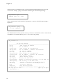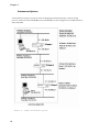
1
GigaFrame Switch Router (GFS/L3)
GFS3012BU/L3
GFS3016BU/L3
User’s Manual
NBase-Xyplex Communications
Manual revision 1.00
May 1999
NBASE-XYPLEX Sales Terms and Conditions for
the Sale and Use of Products and Services Worldwide
1. Products & Services - Hardware, Software licenses and
Services as listed on the then current applicable NBASE-XYPLEX
Price List. Or as otherwise made available by NBASE-XYPLEX in
the case of refurbished Product or Product made available by
NBASE-XYPLEX in connection with any type of Product swap
program. The price that applies to any Purchase Order shall be the
price in effect as of the date of Acceptance of the Purchase Order
by NBASE-XYPLEX.
2. Acceptance of Purchase Order - NBASE-XYPLEX may
reject any Purchase Order(s). The sole terms and conditions to
govern the purchase of any Product are as set forth in these Sales
Terms and Conditions unless issued pursuant to an existing
Agreement between Purchaser and NBASE-XYPLEX referenced
on the face of the Purchase Order. All Services purchased are
subject to the NBASE-XYPLEX Support Agreement(s) applicable to
such Service.
3. Payment Terms - Payment in full for all Products and
Services purchased is due net thirty (30) days from the date of the
NBASE-XYPLEX NETWORK invoice.
4. Shipments - All shipments shall be FOB point of Origin; risk of
loss passes to Purchaser upon delivery to the carrier. Purchaser
may request the manner of shipment and the carrier, but NBASEXYPLEX reserves the right to ultimately designate the manner and
means of any shipment(s). Freight charges, if not stated on the
Price List as being included in the Price, will be billed to Purchaser
separately.
5. Delivery - NBASE-XYPLEX will use reasonable efforts to ship
by the estimated ship date contained in the NBASE-XYPLEX
Purchase Order Acknowledgment, but will not be liable for any
failure to ship by that date, for whatever reason.
6. Title - Title to the Software (including any firmware) and to all
applicable licenses and documentation shall at all times remain in
NBASE-XYPLEX and, to the extent applicable, to its third party
licensors. Title to the Hardware products (excluding any firmware
content) shall pass to Purchaser on delivery, subject to the security
interest that NBASE-XYPLEX retains, and the Purchaser hereby
grants to NBASE-XYPLEX, regarding all Products purchased until
the required and applicable purchase price has been paid in full by
Purchaser.
7. Warranties - PURCHASER ACKNOWLEDGES THAT
NBASE-XYPLEX MAKES NO EXPRESS WARRANTIES
REGARDING PRODUCTS OR SERVICES, THAT ANY
WARRANTIES WHICH COULD BE IMPLIED, INCLUDING, BUT
NOT LIMITED TO ANY WARRANTY OF MERCHANTABILITY,
FITNESS FOR ANY PARTICULAR PURPOSE, COMPATIBILITY,
INTEROPERABILITY, NON-INFRINGEMENT, COMPLIANCE
WITH APPLICABLE SPECIFICATIONS, FREEDOM FROM
DEFECTS, AND ERROR-FREE UNINTERRUPTED OPERATION
ARE EXPRESSLY DISCLAIMED BY NBASE-XYPLEX. ALL
PRODUCTS ARE MADE AVAILABLE HEREUNDER BY NBASEXYPLEX ON AN AS-IS BASIS ONLY.
However, in the event of a Product Defect, if Purchaser provides
NBASE-XYPLEX with written notice of such Product Defect (as
well as with the model and serial number of that Product for
validation purposes) within the applicable period specified below.
NBASE-XYPLEX warrants that it will repair the Product Defect at
no charge, replace the defective Product at no charge, or refund
the net purchase price paid by Purchaser for the defective unit of
Product. This shall be Purchaser’s sole and exclusive remedy, in
contract and at law, regarding that Product, and such warranty is
non-transferable.
a. Hardware - A Product Defect shall mean a defect in Product
materials and workmanship under normal use and service, or a
material failure of the Product to perform substantially in
accordance with the applicable Product specification in a standard
configuration environment, which is reported within one (1) year
(for new Product) or thirty (30) days (for refurbished or swap
Product), of the date it was first shipped by NBASE-XYPLEX to
Purchaser, provided that such failure is not due to any faulty
installation of the Product. NBASE-XYPLEX shall have the option,
but not an obligation, to repair, replace or grant a refund with
regard to the repaired or replaced Product during the remainder of
that same period. If Purchaser is provided with replacement
Product prior to Purchaser’s return to NBASE-XYPLEX of the
allegedly defective Product, NBASE-XYPLEX reserves the right to
invoice Purchaser for the replacement Product (and Purchaser
agrees to pay NBASE-XYPLEX in accordance with the
requirements of that invoice) if the Product being replaced is not
returned to NBASE-XYPLEX, freight prepaid, within thirty (30)
days of Purchaser’s receipt of the replacement Product.
b. Software or Firmware - A Product Defect shall mean a
defect in the media itself, which is reported to NBASE-XYPLEX by
Purchaser within ninety (90) days from the date it was first
shipped by NBASE-XYPLEX to Purchaser. NBASE-XYPLEX shall
have the option, but not an obligation, to repair, replace or grant a
refund with regard to the repaired or replaced Product during the
remainder of that same period.
c. Services - NBASE-XYPLEX’s responsibility and liability for
any defective Service(s) is solely as set forth in the applicable
NBASE-XYPLEX Support Agreements. To the extent NBASEXYPLEX provides any Services without charge, such Services shall
be supplied on an AS-IS basis only, and NBASE-XYPLEX shall bear
no responsibility or liability for such Services.
8. Responsibility - NBASE-XYPLEX’ responsibility for
repairing, replacing or refunding the net purchase price paid by
Purchaser for Products with Product Defects applies only to
Product Defects present when shipped by NBASE-XYPLEX.
Accordingly, and for example, NBASE-XYPLEX is not responsible
for repairing, replacing or refunding the purchase price paid for
Products with Product Defects arising out of any accident, abuse,
misapplication, alteration, attached equipment, improper handling
or installation, improper operation, operation outside of the
environmental specifications for the Products, or, any other cause
outside of NBASE-XYPLEX’s control.
9. Infringement - NBASE-XYPLEX retains the exclusive right
to defend Purchaser against any claim(s) based on a NBASEXYPLEX Product (excluding Third Party Product content)
infringing a patent or copyright. If Purchaser provides NBASEXYPLEX with prompt written notice of a claim(s) or any threat of
such a claim(s), and provided that Purchaser gives NBASEXYPLEX all assistance required in connection with such defense
and Purchaser is not in breach of its obligations hereunder, NBASEXYPLEX will pay all damages finally awarded. However, NBASEXYPLEX may, at its option, settle any such claim(s), purchase a
license under the allegedly infringed patent or copyright, replace or
modify the Product to avoid the infringement asserted, or grant
Purchaser a refund or credit not to exceed the purchase price paid
by Purchaser for the infringing unit(s) of Product. Subject to
Paragraph 10 below, NBASE-XYPLEX’s responsibility or liability
with regard to infringement claim(s) shall apply only to the
infringement of a patent or copyright by the unmodified NBASEXYPLEX Product on a standalone basis. Accordingly, and for
example, NBASE-XYPLEX shall have no responsibility or liability for
any intellectual property infringement claim(s) arising out of the
combination, operation or use of any NBASE-XYPLEX Product(s)
with hardware, software or firmware not owned or licensed by
NBASE-XYPLEX hereunder.
10. Third Party Products - To the extent any Product
includes hardware, software or firmware purchased or licensed by
NBASE-XYPLEX from a third party (“Third Party Products”),
Purchaser’s right to use such third party content shall be subject to
the terms and conditions packaged with such contents. NBASEXYPLEX’ only responsibility and liability for any Third Party
Products shall be limited to passing through whatever warranty
protections, support, licensing and indemnification protections it is
entitled to pass through to Purchaser.
11. License - Subject to the provisions of Paragraph 10 above,
NBASE-XYPLEX grants Purchaser a non-transferable, nonexclusive personal license to use the NBASE-XYPLEX Software at a
Purchaser facility that is owned and controlled by Purchaser, solely
to communicate to NBASE-XYPLEX Hardware at that same facility
for Purchaser’s own end-use purposes at such facilities. Such enduse specifically excludes any right to, and Purchaser agrees not to
(i) decompile, reverse compile, disassemble, reverse engineer or
perform any other activity which has as its purpose or otherwise
results in the derivation of NBASE-XYPLEX Software source code;
(ii) copy except as authorized in Paragraph 13 below; (iii) modify; or
(iv) transfer, the NBASE-XYPLEX Software and/or any
documentation associated therewith. This license will terminate if,
as and when Purchaser fails to comply with any term or condition
of this Agreement.
12. Indemnification - Purchaser agrees to indemnify and
hereby holds NBASE-XYPLEX harmless from any liabilities, claims,
or damages, in contract and at law, arising out of any (i) any act or
omission of Purchaser (including but not limited to any use of a
Product), or (ii) NBASE-XYPLEX’s compliance with Purchaser’s
instructions, specifications or requirements.
13. Backup - Purchaser may make one (1) single copy of the
NBASE-XYPLEX Software solely for backup purposes but provided
that all legends, notices and logos appearing on the original copy
supplied to Purchaser are accurately reproduced on the backup
copy.
14. Audit - NBASE-XYPLEX shall have the right to inspect the
Purchaser’s facility(s) where the NBASE-XYPLEX Products are
located, and to audit Purchaser’s records to satisfy itself that
Purchaser is complying with all requirements of this Agreement.
15. Product and Methods of Doing Business Changes
NBASE-XYPLEX reserves the right to modify as well as obsolete any
and all of its Products, associated Product offerings as well as the
basis of their availability, at any time and without notice.
16. Insolvency - In the event of any proceedings, voluntary or
involuntary, in bankruptcy or insolvency, brought by or against
Purchaser, including any proceeding under the applicable Federal
or State Bankruptcy law currently in effect, or in the event of the
appointment, with or without ‘NBASE-XYPLEX’ consent, of any
assignee for the benefit of creditors or of a receiver, NBASEXYPLEX shall be entitled to accelerate the due date for payment of
any invoices then outstanding and to cancel any unfilled part of
any outstanding Purchase Order issued by Purchaser, without
liability or penalty.
17. Overshipment or Undershipment - Purchaser shall be
obligated and agrees to promptly pay for all Products in accordance
with Paragraph 3. Shipment to Purchases of less than the quantity
of Products ordered shall not entitle Purchaser to withhold
payment for those Products already received. Shipment of more
than the quantity of Products ordered shall entitle Purchaser to
withhold payment for Products not ordered, provided such
Products are shipped (prepaid) back to NBASE-XYPLEX in their
original, unopened containers, within ten (10) days of their receipt.
18. Data Rights - The NBASE-XYPLEX Software Products and
the software programs contained in any Third Party Products, as
well as the related documentation, are “commercial computer
software” or “commercial computer software documentation”.
Purchaser’s rights with respect to such NBASE-XYPLEX Products,
Third Party Products and documentation are limited by the
NBASE-XYPLEX terms and conditions set forth herein or which
are otherwise published, pursuant to FAR 12.212(a) and/or DFARS
227.7202-1(a), as applicable.
19. High-Risk - The NBASE-XYPLEX Products and Third Party
Products purchase hereunder are not fault-tolerant and are not
designed, certified, manufactured or intended for use in hazardous
environments requiring fail-safe or uninterrupted performance,
including without limitation, the operation of nuclear facilities,
aircraft navigation or communication systems, air traffic control,
direct life support machines, weapons systems, or disposal of
hazardous waste, in which the failure of such software programs
could lead, directly or indirectly, to death, personal injury, or severe
physical or environmental damage (“High Risk Activities”).
Purchaser agrees not to in any manner represent, directly or
indirectly, that any NBASE-XYPLEX Product or Third Party
Product is in any way suitable for such Activities. NBASE-XYPLEX
HAS NOT MADE ANY EXPRESS WARRANTIES, AND
SPECIFICALLY DISCLAIMS ALL WARRANTIES THAT COULD
BE IMPLIED, INCLUDING BUT NOT LIMITED TO WARRANTIES OF FITNESS FOR ANY PARTICULAR PURPOSE SUCH AS
HIGH RISK ACTIVITIES. Purchaser shall, and agrees to
indemnify and hereby holds NBASE-XYPLEX harmless from and
against any and all claims for losses, costs, damages, expenses, or
liability that may arise out of, or be connected with, Purchaser’s
failure to comply with this obligation.
20. Limitation of Remedies - TO THE EXTENT
ENFORCEABLE, AND AS PART OF THE BARGAINED FOR
CONSIDERATION, NBASE-XYPLEX’S LIABILITY, IN
CONTRACT AND AT LAW (IRRESPECTIVE OF FAULT OR
NEGLIGENCE), SHALL BE LIMITED TO DIRECT DAMAGES
SUFFERED BY PURCHASER AND SHALL BE LIMITED TO THE
PURCHASE PRICE PAID BY PURCHASER TO NBASE-XYPLEX
FOR THE NBASE-XYPLEX PRODUCT(S) THAT IS/ARE THE
SUBJECT OF A SPECIFIC CLAIM. IN NO EVENT SHALL
NBASE-XYPLEX BE RESPONSIBLE OR LIABLE TO PURCHASER
OR TO ANY THIRD PARTY FOR ANY DAMAGES, HOWEVER
CHARACTERIZED, WHICH EQUATE TO LOST PROFITS, LOST
SAVINGS, LOSS OF USE, LOSS OF BUSINESS OPPURTUNITES,
OR ARE PUNITIVE, INCIDENTAL, SPECIAL, INDIRECT, OR
CONSEQUENTIAL IN NATURE, OR WHICH OTHERWISE
ARISE OUT OF THE USE OF OR INABILITY TO USE ANY
NBASE-XYPLEX PRODUCT(S) OR THIRD PARTY PRODUCTS,
EVEN IF NBASE-XYPLEX WAS ADVISED OF THE POSSIBILITY
OF SUCH DAMAGE. IN NO EVENT SHALL NBASE-XYPLEX’S
CUMULATIVE MAXIMUM AGGREGATE LIABILITY EXCEED
THE TOTAL PURCHASE PRICE PAID HEREUNDER BY
PURCHASER FOR NBASE-XYPLEXPRODUCTS.
21. Assignment of Rights - Purchaser shall not delegate any
duties nor assign any rights or claims under this contract or for
breach thereof without the prior written consent of NBASEXYPLEX, and no attempted delegation or assignment absent such
consent shall be binding on NBASE-XYPLEX.
22. Remedies - The rights and remedies provided to Purchaser
herein shall be exclusive and in lieu of any other rights and
remedies provided by law or equity (or provided under the
Uniform Commercial Code).
23. Waiver - Waiver of a breach of any of these terms and
conditions shall not constitute waiver of full compliance with such
provision, nor shall it be construed as a waiver of any other breach.
24. Governing Law - These terms and conditions shall be
interpreted, governed and enforced in all respects according to the
laws and by the courts of the Commonwealth of Massachusetts
(excluding its conflicts of law provisions).
25. Export - Purchaser agrees not to ship, transfer or export,
directly or indirectly, any Products nor any direct product thereof,
outside of the U.S. unless in full compliance with all applicable
export requirements, and in no event into any country prohibited
by the United States Export Administration Act and the regulations
thereunder.
26. Acknowledgment - PURCHASER REPRESENTS THAT IT
HAS READ AND UNDERSTANDS THIS AGREEMENT, HAS
HAD THE BENEFIT OF LEGAL COUNSEL IN THIS REGARD,
AND AGREES TO BE BOUND BY THESE TERMS AND
CONDITIONS. THIS AGREEMENT IS THE COMPLETE AND
EXCLUSIVE STATEMENT OF THE UNDERSTANDINGS
REACHED BETWEEN PURCHASER AND NBASE-XYPLEX AND
SUPERCEDES ALL PROPOSALS, AND PRIOR WRITINGS AND
AGREEMENTS, VERBAL OR WRITTEN, BETWEEN THESE
PARTIES RELATING TO THE SUBJECT MATTER OF THIS
AGREEMENT.
FCC Notice
WARNING:
•
This equipment has been tested and found to comply with the limits for a Class A digital
device, pursuant to Part 15 of the FCC Rules. These limits are designed to provide reasonable
protection against harmful interference when the equipment is operated in a commercial
environment. This equipment generates, uses, and can radiate radio frequency energy and, if
not installed and used in accordance with the instruction manual, may cause harmful interference to radio communications. Operation of this equipment in a residential area is likely to
cause harmful interference in which case the user will be required to correct the interference at
his own expense.
•
The user is cautioned that changes and modifications made to the equipment without approval
of the manufacturer could void the user’s authority to operate this equipment
•
It is suggested that the user use only shielded and grounded cables when appropriate to ensure
compliance with FCC Rules.
•
This unit has no operator serviceable parts. Repair is for certified technicians.
Copyright © NBase-Xyplex. All Rights Reserved. No part of this publication may be reproduced, transmitted, transcribed, stored in a retrieval system, or translated into any language,
in any form or by any means, electronic, mechanical, photocopying, recording or otherwise,
without the express written permission of NBase-Xyplex.
The digitally encoded software included with this product is copyrighted by NBase-Xyplex and
MultiPort Corporation. All Rights Reserved. This software may not be reproduced, modified,
displayed, transferred, or copied in any form or in any manner or on any media, in whole or
in part, without the express written permission of NBase-Xyplex, except in the normal use of
the software to make a backup copy.
Information in this manual is subject to change without notice and does not represent a
commitment on the part of NBase-Xyplex. The software described in this manual is furnished
under a license agreement and may only be used or copied in accordance with the terms of the
agreement.
All products and brand names are trademarks or registered trademarks of their respective
holders.
Nbase-Xyplex
295 Foster Street
Littleton, MA 01460-2016
Tech Support: (800) 435-7997
International Support: +978 952-4888
E-mail: [email protected]
Fax: (978) 952-4880
URL: http://www.nbase-xyplex.com
Contents
Chapter 1: System Overview ........................................................... 12
1. Description ............................................................... 12
Features .................................................................................. 14
Options .................................................................................... 15
2. Typical Configurations ............................................ 16
Configuring Your Network......................................................... 16
Typical Network Applications ................................................... 16
3. Installing the GFS3012/GFS3016 Chassis and Modules ...... 20
Installing the GFS..................................................................... 20
Installing the FPM Board .......................................................... 21
Understanding the Front Panels ............................................... 22
4. Troubleshooting ...................................................... 26
5. Technical Specifications ........................................ 28
Chapter 2: Administrative Interface ................................................ 30
System Concepts ......................................................... 30
Overview .................................................................................. 30
The RS232 Interface ................................................................ 30
Command Line Interface .......................................................... 30
Users, access rights, and Logging in and Out .......................... 33
First Time Login ....................................................................... 34
Telnet ....................................................................................... 34
Boot Sequence, and Restarting the System ............................. 34
TFTP ........................................................................................ 35
Upgrading the system software ............................................... 35
Message Logging..................................................................... 35
NVRAM .................................................................................... 36
System Control ........................................................................ 36
Ping .......................................................................................... 37
Frame Generator ..................................................................... 37
Ports and Interfaces ................................................................ 38
Parameter Upload/Download ................................................... 38
Chapter 3: Bridging Configuration Guide ....................................... 39
Overview ...................................................................... 39
Learn Table .............................................................................. 39
Installing and Deleting Addresses ............................................ 39
Trustee Lists (Max – 32) .......................................................... 40
Tag Lists (Max – 32) ................................................................ 40
Policies (Max – 32) .................................................................. 40
Virtual LANs (Max – 64) ........................................................... 41
VLANs General Configuration Modes ....................................... 43
Inter Switch VLAN (ISVLAN) .................................................... 43
TCI ........................................................................................... 44
Custom Filters (Max – 32) ....................................................... 44
Port Mirroring (Max-8) ............................................................. 45
Port Trunking or Ether Channel ................................................ 45
Spanning Tree.............................................................. 47
Overview .................................................................................. 47
Port States and Topology Changes .......................................... 47
Configuring ............................................................................... 48
Enhancements.......................................................................... 49
Controlling SNMP ........................................................ 50
Overview .................................................................................. 50
Community Strings ................................................................... 50
Traps ....................................................................................... 50
Authentication ........................................................................... 51
Chapter 4: IP Routing Guide ............................................................ 52
Overview ...................................................................... 52
How IP Routing Works ............................................................. 53
Link Detect Feature ................................................................. 53
Basic IP Routing Configuration Steps ....................................... 54
Saving Configuration Information .............................................. 54
Defining an IP Interface............................................................ 54
Subnet Mask vs. Prefix Mask ................................................... 55
Modifying an IP Interface ......................................................... 56
Deleting an IP Interface, IP Subnets and IP Ports ................... 56
Deleting Ports from an IP Interface .......................................... 56
Displaying the NVRAM Database ............................................. 57
Clearing the NVRAM IP Interface Database ............................ 57
Clearing all Routing Configurations ........................................... 57
Displaying IP Interfaces ........................................................... 57
Displaying the Current Port Assignments to an IP Interface ..... 58
Displaying an IP Interface Configuration .................................. 58
Displaying the Routing Table .................................................... 59
Displaying Route Attributes ...................................................... 60
Static Routes................................................................ 61
Definition of an Autonomous System ........................................ 61
Autonomous Systems .............................................................. 62
Using Static Routes .................................................................. 63
Deleting Static Routes.............................................................. 64
Displaying Static Routes .......................................................... 64
Clearing Static Routes from NVRAM ....................................... 64
Setting the Default Gateway .................................................... 64
Proxy ARP ..................................................................... 66
Overview .................................................................................. 66
Enabling Proxy ARP on the GFS 3012BU/L3 AND GFS 3016BU/L3 .. 67
Enabling Proxy ARP on an IP Interface .................................... 67
Checking Proxy ARP Statistics ................................................ 69
BOOTP/UDP Broadcast Relay ................................................ 70
Enabling UDP Broadcast Relay ................................................ 70
Forwarding UDP Packets to Servers ....................................... 70
Adding a UDP Broadcast Server .............................................. 71
Deleting a Server from the UDP Broadcast Relay Agent Server List .. 71
Displaying UDP Broadcast Relay Server Statistics .................. 71
Clearing the NVRAM UDP/BOOTP Database .......................... 72
Managing UDP Ports ............................................................... 72
BOOTP Relay Agent ................................................................ 73
BOOTP Relay Agent Server Settings ...................................... 73
Viewing the BOOTP Hops Threshold Setting ........................... 74
Using a Routing Protocol (OSPF or RIP) ................... 75
RIP Configuration ........................................................ 76
Overview .................................................................................. 76
Basic RIP Configuration Steps ................................................. 76
Re-enabling or Disabling RIP on the GFS 3012BU/L3 and GFS3016BU/L3 . 76
Disabling the RIP Process ....................................................... 77
RIP Interface Modes ................................................................ 77
Adding or Deleting IP Interfaces to RIP ................................... 77
Deleting a RIP Interface ........................................................... 78
Setting the RIP Interface Cost ................................................. 78
Default RIP Routes .................................................................. 78
Defining or Deleting a Default Route ........................................ 78
Displaying the RIP Routing Table ............................................. 79
Displaying RIP Status .............................................................. 80
Displaying RIP Status for an Interface ..................................... 80
OSPF Configuration .................................................... 83
Overview .................................................................................. 83
How OSPF Works ................................................................... 83
OSPF Features on the GFS/L3................................................ 83
Basic OSPF Configuration Steps ............................................. 84
Defining a Router ID for OSPF ............................................... 84
Setting OSPF Version Compatibility ......................................... 85
Defining an OSPF Area ............................................................ 85
Adding an OSPF interface ...................................................... 86
Enabling/Disabling an OSPF Interface ..................................... 86
Defining OSPF Interface Types................................................ 86
Deleting an OSPF Interface ..................................................... 87
Exporting from OSPF to RIP and from RIP to OSPF ............... 87
Exporting from RIP to OSPF .................................................... 87
Exporting from OSPF to RIP .................................................... 88
Changing the Exporting Cost .................................................... 88
Rip Tunneling through OSPF .................................................... 88
Configuring OSPF Areas .......................................................... 89
Deleting OSPF Areas ............................................................... 89
Configuring OSPF External Routes .......................................... 90
Deleting OSPF External Routes ............................................... 91
Clearing the OSPF NVRAM Database ..................................... 91
Displaying OSPF Tables .......................................................... 91
OSPF Routing Table ................................................................ 91
OSPF Ranges .......................................................................... 94
OSPF Database Configurations ............................................... 95
OSPF Link State Advertisements (LSAs) ................................. 97
LSA Types ............................................................................... 97
Viewing OSPF Configurations ................................................ 100
OSPF Virtual Link Settings ..................................................... 102
Creating OSPF Virtual Links .................................................. 102
Setting OSPF/Virtual Links Timers ......................................... 104
Deleting an OSPF/Virtual Link ................................................ 104
Displaying OSPF/Virtual Links ................................................ 104
Displaying the OSPF/Virtual Links Neighbors Table ............... 105
Optional OSPF/ Virtual Link Settings ..................................... 106
OSPF Timers ......................................................................... 107
Setting the Dead Interval ........................................................ 107
Setting the Transmit Delay ..................................................... 108
Setting the Hello Interval ........................................................ 108
Setting the Metric ................................................................... 109
Setting the Priority ................................................................. 109
Setting the Retransmit Interval ............................................... 109
Setting the Stub Area ............................................................. 110
Enabling/Disabling an AS Boundary Router ............................ 110
Deleting an OSPF Interface ................................................... 111
Chapter 5:Commands and Descriptions ....................................... 112
Console Commands: ................................................. 112
IP Routing and Related Commands ....................................... 116
UDBC/BOOTP Relay ............................................................. 123
Rip Protocol ........................................................................... 125
OSPF Protocol Related Commands....................................... 129
FPM Related Commands ....................................................... 138
Console Command Line Reference ........................................ 139
Console Commands ............................................................... 139
IP Router Related Commands ............................................... 139
UDBC/BOOTP Relay ............................................................. 140
RIP......................................................................................... 140
OSPF Protocol Related Commands....................................... 141
Port Configuration .................................................................. 142
Statistics ................................................................................ 142
Module Related Commands ................................................... 142
Spanning Tree Commands ..................................................... 142
Email ...................................................................................... 143
Chapter 6: Using an SNMP Manager ........................................... 144
Configuring the GFS3012/GFS3016 with an SNMP Agent ..... 144
Global Setup .......................................................................... 144
IP Setup ................................................................................. 145
SNMP Setup .......................................................................... 145
Chapter 7: Troubleshooting.......................................................... 147
Appendix A. System Default Values .............................................. 148
console .................................................................................. 148
system ................................................................................... 148
ip ............................................................................................ 148
snmp ...................................................................................... 148
switch-db ............................................................................... 148
port configuration ................................................................... 148
spanning tree ......................................................................... 148
Router .................................................................................... 149
OSPF Defaults ....................................................................... 149
OSPF Interface Defaults ........................................................ 149
RIP Defaults........................................................................... 149
Other Defaults........................................................................ 149
Appendix B. InterSwitch Virtual Networking ................................ 150
Overview .................................................................... 150
VLAN implementation: A technical overview: .......................... 151
NBase-Xyplex Networks InterSwitch Virtual Networking ........ 152
VLAN Example ....................................................................... 152
Spanning Tree and InterSwitch Virtual Networking ................. 153
Chapter 1
Chapter 1: System Overview
1. Description
The Frame Processing Router for the GFS 3012BU/L3 and GFS 3016BU/L3 (FPM)
provides true ASIC based routing for the GFS3012 GigaFrame Switch series. The
FPM has the ability to route over 2 million packets per second and switch 5.4
million packets per second. The GFS and the FPM provide a solid platform for
building Enterprise class backbones. The pirmary feature of the FPM is IP routing.
Other protocols such as IPX and Appletalk are not routed, but may be bridged.
The GFS is capable of aggregating multiprotocol traffic from multiple wiring closets
via a combination of 4 port Gigabit and 16 port 10/100Mbps ethernet switching
modules. ATM (OC3 and OC12) and FDDI uplinks provide connectivity to most
types of coporate networks. The FPM has an uplink slot to further increase the port
density of the GFS. Single and dual Gigabit, or 8 10/100Mbps TX modules are
currently available. To further increase port density, the FPM has two slots which
may be populated with a variety of uplink modules such as 10/100BaseT/TX,
100BaseFX, Gigabit ethernet, or ATM. The FPM is a separate produce from the GFS,
and comes complete with a control board, and the FPM routing board.
The FPM provides the following functions:
In a Layer 2 switch configuration, frames may be VLANtagged and untagged so
that both trunk and node ports on the GFS3012/GFS3016 can participate in InterSwitch VLANS (IS-VLANs).
*Note:VLANs based on IP protocol is not allowed, because the GFS Router would
handle IP traffic on the network.
In a Layer 3 switch configuration with IP firmware (Routing), the FPM can process
over 2 million packets per second
The GFS3012BU/L3 and GFS3016BU/L3 Switch Router is the latest edition of
NBase-Xyplex’s family of Gigabit switching/routing products, and supports the
requirements of the next wave of networking; more bandwidth, elimination of
bottlenecks, better manageability, and dependable multimedia support.
12
System Overview
The GFS is a store and forward Gigabit Ethernet Switch Router. The GFS is
available in a 4-slot or 6-slot chassis, and can accommodate a variety of different
modules and supports up to 16 gigabit ports or 62 10/100 ports, all with selectable
half or full duplex. The GFS provides a cost effective solution for high speed
backbone switching. It combines wire speed routing at gigabit rates, and its
superior routing capacity meets the needs of today’s and tomorrow’s networks. A
typical GFS chassis includes a management module, and can support four
additional modules. Modules available include:
a.
4 Gigabit fiber-optic ports
c. 8 100 Mbit/sec fiber-optic ports
b.
16 10/100 TX ports
d. Frame processor module(FPM)
that supportsVLAN tagging and de-tagging
Broadcast and security domains may be defined, creating “Virtual Networks” that
allows secure workgroups and better management of network traffic. Any wire
speed filter can be defined based on: multicast/broadcast, source port, destination
port, MAC address, protocol, and VLAN tag.
The 6-slot GFS offers fault tolerant architecture with redundant power supplies and
hot-swappable fans module.
Each 1Gbps port supports a Gbps segment with fiber optic full duplex connectivity.
NBase-Xyplex offers several different fiber options to precisely meet your distance
requirements: links of up to 95Km are possible.
Delays in data transfer are eliminated through the GFS’s unique store and forward
architecture with direct port to port transfer. Its proprietary hardware enables the
GFS to have a filter and forwarding rate of 5.4M packets per second.
The GFS can operate as an enterprise backbone switch router in conjunction with
any of the NBase-Xyplex ethernet switching products such as the GFS3012/3016
Switch, MegaSwitch II series switches, the MegaSwitch 5000 series, the MegaSwitch
G series, and the GigaHub. The GFS does not require special network management
software and can be monitored and managed with any SNMP based network
management software (NMS) if so desired. Only in-band management is supported
on the GFS, on a port with an IP interface (explained later in the Configuration
Guide). A robust console is provide; however, network management tasks are
simplified with a full suite of SNMP MIBS that allow the FPM to be configured from
any SNMP based management station. The Trivial File Transfer Protocol (TFTP) can
be used to update Flash memory with new revisions of the operating system
without hardware changes. NBase also offers a comprehensive GUI based multiplatform NMS, Megavision. Megavision eases management of the GFS/FPM, and
all other NBase products, and any SNMP device. For more information on
Megavision, visit our web site at www.nbase.com, or contact your local NBase
representative.(www.nbase-xyplex.com).
13
Chapter 1
Features
The GFS3012/GFS3016 Router series supports the following features:
•
IP Routing (RFC 1812)
•
RIPv1 and RIPv2
•
OSPF
•
BOOTP and UDP Broadcast relay
•
ICMP
•
Proxy ARP
•
Time Protocol
•
802.1 IVLAN Tagging
•
Bridging
•
Class of Service (CoS) with a two level priority scheme per:
• source and destination address
• protocol
• VLAN-ID
• Multicast and Unicast frames
•
VLAN support based on:
• Source port
• MAC source and destination address
• protocol type
• tag per 802.1q
•
IP Multicast support
•
Ethernet and serial terminal based administrative interface port on the
module, providing switch configuration and management
•
Downloadable system for software and hardware upgrades (serial or TFTP)
•
Full SNMP support
•
RMON support (Groups 1, 2, 3, and 9)
•
Spanning Tree
•
Telnet
14
controller
System Overview
•
Auto ranging power supplies
•
Flow Control ensures zero packet loss
•
4096 MAC address cache entries
•
8Gbps bandwidth
•
256Kb buffer per port
•
Switching Forwarding rate of 5.4M packets per second
•
Routing Forwarding rate: 2 million packets per second
•
Forwarding table size (routing and ARP): 8,000 entries
•
Up to 4 different subnets per IP interface
•
Up to 4 parallel (equal) paths for routing (static or OSPF)
Options
•
Five versions of the 19” rack mount chassis are:
GFS3012BU
- 5.25 in. high version supports up to 3 port modules
GFS3012BU/R - 8.75 in. high version supports redundant power supplies and
up to 3 port modules
GFS3012BU/L3 - 5.25 in. high switch routing version supports up to 3 port modules
GFS3016BU
- 8.5 in. high switch version supports up to 4 port modules, and has hotswappable fans and redundant power supplies.
GFS3016BU/L3 - 8.5 in. high switch router version supports up to 4 port modules, and
has hot-swappable fans and redundant power supplies.
•
Available port modules includes:
• 4 switched Gigabit Ethernet ports for 1000BaseLX or SX with multi or single
mode fiber
• 16 switched 10/100BaseTX ports
• 8 switched 100Base FX ports
• Frame Processor Module (FPM) to support VLAN tagging and de-tagging with
capability to hold two Gigabit Uplink.
• Gigabit Uplink port for Frame Processor Module in either SX or LX models.
15
Chapter 1
2. Typical Configurations
Configuring Your Network
Links to a file server and links between switches often create bandwidth
bottlenecks. When a dedicated 100Mbps link is not fast enough, or when a network-wide upgrade path is planned, Gigabit Ethernet is the most viable solution.
Typical Network Applications
Typical network applications for the GFS are:
•
Central backbone switch router for buildings or campus environments, with Gigabit
speeds
•
Any application that needs a Gigabit Ethernet switch with up to 62 10/100 ports
Below is an example of a GFS3012 or GFS3016 as a Gigabit Ethernet backbone switch router
with connectivity to either the MegaSwitch II, MegaSwitch 5000, or to GigaHub switch
router with connections to Gigabit Ethernet server farms. The GFS is located in the center of
the switched network surrounded by edge devices using Gigabit Ethernet uplink ports:
16
System Overview
•
Any combination of 10/100 Mbps and 1000Mbps ports
The Gigabit Ethernet ports are connected to centralized servers equipped with Gigabit
Ethernet adapters and the 100Base-FX ports are connected to 10/100 Mbps
MegaSwitch II series devices.
You can use theGFS3012 or GFS3016 as a gigabit Ethernet desktop switch router for high-end
stations such as CAD/CAM, publishing, or backup servers. These stations typically require
short response time during the transmission of gigabyte files over the switched network.
17
Chapter 1
You can also use the GFS3012 or GFS3016 to migrate from a distributed Gigabit Ethernet
topology to a switch router Gigabit Ethernet backbone as shown in the following illustration:
18
System Overview
By using the Layer -2 VLANs and/or Layer- 3 switching/routing features of the GFS, more
packet control and network security is added:
19
Chapter 1
3. Installing the GFS3012/GFS3016 Chassis and
Modules
Installing the GFS
Complete the following step-by-step instructions to successfully install the GFS3012/
GFS3016 into your network:
1:
Determine the best location for the GFS
Affix the GFS to a 19” rack using the enclosed rack mount ears, or place the unit on a
secure flat surface. Ensure that the unit is within reach of the necessary connections
(i.e. power outlet, Ethernet connections, and a PC, UNIX workstation, or modem, if
the Switch will be monitored via the serial port).
2:
Plug in the Switch
Connect the power cord(s) to the switch and an outlet. Turn the power switch(es) to
the ON position. The power supply automatically adjusts to any outlet providing
between 90 VAC and 264 VAC at 50/60 Hz. Use the following types of power cords:
For a 115 Volt configuration - Minimum type SJT (SVT) 18/3, rated 250 AC, 10
Amps with a maximum length of 15 feet. One end terminated in an IEC 320 attachment plug. The other end in a NEMA 5-15P plug. This is the cord normally supplied with the GFS.
For a 230 Volt configuration - Minimum type SJT (SVT) 18/3, rated 250 Volts AC,
10 Amps with a maximum length of 15 feet. One end is terminated in an IEC 320
attachment plug. The other end terminated as required by the country where it will
be installed.
Le cable de transport d’energie que doit etre utilisé la configuration 230 Volts est le type
minimum SJT (SVT) 18/3, nominal 250 Volts AC, 10 Amps, 4.5m long maximum. Un
bout est raccorde comme exige par le pays ou il sera utilisé.
Das Netzkabel ist das hauptsachliche Diskonnektionsmittel, es sollte in eine leicht
erreichbare steckdos gesteckt werden. Das Netzkabel kann mit einer 230 Volts
Konfiguration verwonder werden vom typ: Minimum VDE or HAR, 3 X 1.00 mm2, 250
VAC, 10 Amps, maximal 4.5m long. Ein Ende ontspriche dem Stecker IEC 320. Das
andere Ende entspricht den Anfoderungen des entsprechenden Landes.
20
System Overview
The redundant power supply option is available in 2 of the 3 GFS chassis options. No
special operation action is required to support this option; just plug in each power
supply and turn it on. The power modules are hot swappable; either one may be
replaced without affecting operation of the GFS.
3:
Connect the Ethernet Devices
For optimum performance, the Ethernet segments connected to the GFS must be configured carefully. Generally, the segments should be configured so that machines on a
given port communicate primarily among themselves; i.e. most traffic does not need to
cross the switch. However, there are situations for which this is not the best configuration.
Note: for configuration examples please refer to Section 2 of this Installation Guide.
4.
What to do next
If you are using the GFS as a stand alone device please refer to Section 4 in the Administrative Interface later in this manual.
If the GFS will be controlled by MegaVision, please refer to your MegaVision User Guide
for instructions on using the switch with MegaVision.
Installing the FPM Board
Complete the following step-by-step instructions to successfully install the
GFS3012/GFS3016 module into your network. If you ordered the FPM board with a
chassis, you may skip this section. *Note: A FPM board is required for routing.
1:
Power down the GFS.
2.
Insert the FPM board into a free shot. Make sure the edges of the board are
aligned with the metal guides.
3.
Make sure the board is flush with the front of the GFS3012/GFS3016 chassis
before tightening the two retaining screws.
4.
Attach data cables.
5.
Power on and configure the GFS.
6.
Although the FPM module, and any other modules may populate any slot, the
control board must be left in Slot 1.
21
Chapter 1
Understanding the Front Panels
Any version of the GFS3012 or GFS3016 Chassis includes a management module
and can accept several data modules. The available modules include:
1.
Management module
The Management Module has three connectors and status LEDs:
a.
Two RJ-45 10BaseT connectors for out-of-band management. One is an MDI
connector for use with a straight cable to a management station. An MDI-X
connector is also provided to facilitate cabling.
The RJ-45 ports have 4 LEDs:
• RX: Receive frames
• TX: Transmit frames
• Col: Collision indicator
• Link: Valid link indication
*NOTE: If link LED is on; there is a valid link. If link LED is off; there is not a valid link. If link LED is
flashing; there is a mis-configuration.
b.
One DB9 serial connector (male) for out-of-band connections.
The DB9 serial connector has 6 system LEDs adjacent to it:
• Test: Self test active
• Fault: Flashes when the self test fails
• Pwr: System power is on
• Act: Flashes when hardware configuration active
• PS1 Ok: Main power supply active and ok
• PS2 Ok: Secondary power supply active and ok
2.
Four port multi-mode Gigabit Module (EM3012GE (LX or SX)).
The four port gigabit module has two DSC fiber connectors and six LED indicators
per port:
• Xmt: Transmit frames
• Rx: Receive frames
• Err: Receive error
• Fc: Flow control active
22
System Overview
• Mgmt: on - spanning tree forwarding; off - spanning tree blocked/disabled;
flashing - listening and learning
• Link: Valid link indication
*NOTE: If link LED is on; there is a valid link. If link LED is off; there is not a valid link. If link LED is flashing;
there is a mis-configuration.
The module also has two LEDs on the left side, which indicate:
• Act: the GFS management is accessing the module, for purposes like statistical
operations, polling, or configuration changes
• Err: this LED flashes when the self-test process has detected an error on this
module.
3.
Sixteen port 10/100BaseTX Module (EM3012-16TP)
The sixteen port 10/100 module has 16 RJ-45 connectors, each with two built-in LEDs
• the upper left LED indicates transmit/receive
• the upper right LED indicates link speed (10Mbps is yellow, 100Mbps is green)
The module also has two LEDs on the left side, which indicate:
• Act: the GFS management is accessing the module, for purposes like statistical
operations, polling, or configuration changes
• Err: this LED flashes when the self-test process has detected an error on this
module.
4.
Redundant Power Supply (RPS)
Each RPS module has a “power good” LED, and on/off switch, and a power cord.
The GFS will operate properly if either module:
• is installed into the chassis
• has a power cord installed, with 90-260VAC applied
• is turned ON
• has a “power-good” indicator illuminated
The modules are hot-swappable; if one module is plugged in and turned ON and
shows no “power-good” LED on the management control board, then it should be replaced
with a good module.
23
Chapter 1
5.
Eight Port Multi-mode 100Base FX Module
The eight port 100Base FX module has two DSC fiber connectors and 4 LED
indicators per port:
• Xmt: Transmit frames
• Rx: Receive frames
• Fd: Full Duplex
• Link: Valid link indication
*NOTE: If link LED is on; there is a valid link. If link LED is off; there is not a valid link. If link LED is
flashing; there is a mis-configuration.
The module also has two LEDs on the left side that indicates:
• Act: The GFS management is accessing the module, for purposes like statistical
operations, polling, or cofiguration changes
• Err: This LED flashes when the self-test process has detected an error on this
module
6.
Frame Processor Module(EM3012FP)
The frame processor module adds and strips VLAN tags from the frames, and it has eight
LED indicators on the front panel. Also, FPM processes IP routing.
• Act: Indicates activity on the FPM module, or indicates activity on either of the
two uplink modules installed in the FPM module
• Err: Error occured during self-test
• Tx: FPM is sending data to the backplane
• Rx: FPM is receiving data from the backplane
• VLAN: Tag is being added or stripped
• Nf: Indicates an IP frame was not found
• IP: Indicates a frame is being routed
7.
Gigabit Module Uplink for the FPM:
The FPM’s gigabit uplink module has two DSC fiber connectors and six LED
indicators per port:
• Xmt: Transmit frames
• Rx: Receive frames
• Rx: Receive frames
24
System Overview
• Err: Receive error
• Fc: Flow control active
• Mgmt: On - spanning tree forwarding; Off - spanning tree blocked/disabled;
Flashing - listening and learning
• Link: Valid link indication
*NOTE: If link LED is on; there is a valid link. If link LED is off; there is not a valid link. If link LED is
flashing; there is a mis-configuration.
25
Chapter 1
4. Troubleshooting
The GFS is a highly reliable unit. If there are any operating problems, the fault probably
lies in some other aspect of the configuration. However, if after following the troubleshooting steps below (in order), you find that the Switch Router is still not functioning correctly, please contact your local NBase-Xyplex representative:
1.
Ensure that the unit is plugged into a grounded, functioning AC outlet
between 90 VAC and 264 VAC at 50/60 Hz.
providing
2.
Review all link LEDs to ensure that those ports you believe should be
ing are properly attached to a cable.
3.
If you still have a problem with attaining link, verify that the fiber optic cable budget
is within the range specified in the technical specifications.
4.
Review all link LEDs to ensure that those ports you believe should be
functioning are properly configured, and not disabled or partitioned. If the suspect ports are
disabled or do not seem configured properly, re-configure the port through SNMP
management or the Administrative Interface.
5.
If the Flow Control LED shows excessive activity, refer to Chapter 1, Section 2 for a
discussion of how to best configure your network for operation with a switch.
6.
If link LED is on there is a valid link. If link LED is off, there is not a valid link. If link
LED is flashing, there is a mis-configuration.
7.
If there is trouble with link or with excessive errors on any Fiber Optic connec-
function-
tion, ensure that the cable type matches the optic type of the port (multimode vs.
singlemode).
8.
Ensure that the equipment attached to the switch router is properly configured.
If you encounter any situations or problems you cannot solve, obtain, if possible, the
following information:
• The serial number of your Switch Router and its hardware address.
• The configuration of the equipment that is being interfaced with the Switch Router.
• The sequence of events leading up to your problem.
• Actions you have already taken.
26
System Overview
When you have compiled the above information, contact your local NBase-Xyplex
representative or a Customer Service Representative. Customer support in the US is
available at 1-800-435-7997. International customers may call +978-952-4888.
E-mail: [email protected] (US)
Visit the NBase-Xyplex web site at http://www.nbase-xyplex.com/ to:
• Download the latest version of this document
(www.nbase-xyplex.com/pdf)
• View NBase-Xyplex product data sheets
• Download the latest version of NBase-Xyplex’s Management
software
• Download the latest flash upgrade
• Look at application notes and white papers
27
Chapter 1
5. Technical Specifications
Buffers
256KB per port (GB Board)
Addresses
4096 MAC Addresses
Addresses Filtering
Transparent, automatic self learning
at full wire speed. Cache aging time
manageable. Custom filtering by MAC
address, port, and protocol.
Store-and-Forward Switching
Provides complete runt and error
filtering on all packets. Flow control
prevents packet loss.
Standards Supported
IEEE802.3z GigaBit Ethernet
IEEE802.1q VLAN Tagging
Support
IEEE802.1d Bridge/Spanning
Tree
SNMP RFC 1157, etc.
MIB II RFC 1213, etc.
Bridge MIB RFC 1493
RMON Groups 1, 2, 3, and 9
Mounting
Tabletop or Standard 19” rack,
with mounting brackets.
Network Management
Physical Connectors
In-band and out-of-band SNMP, all
standard MIBs, private MIB, RMON
MIB (4 groups), and out of band serial
console support.
Filter/Forward Rate
5,400,000 pps
Learning Rate
5,400,000 pps
Boot and Configuration
NVRAM configuration is loaded on
power up and is fully downloadable.
Firmware is local/remote
downloadable.
Interfaces
Management: UTP RJ-45 and RS-232
DB-9. Three or four slots for port
modules.
28
Management cables:
a. RJ-45 (MDI and MDI-X)
b. DB9 serial cable
Data cables:
a. RJ-45 MDI-X (16 port module)
b. Dual SC (4-port gigabit
module and 8-port gigabit module
and gigabit uplink modules)
Environment
Operating temperature:
5 ~ 40° Celsius
Storage temperature:
-10 ~ 65° Celsius
<95% humidity (non-condensing)
System Overview
Emissions & Safety
FCC Part 15, Class A
TUV GS Mark
CE Mark
EN 60950
IEC 950
EN 55022, Class A
VCC I, Class A
UL 1950
CSA 22.2
Cooling
Redundant DC Fans for electronics modules
One DC fan per power supply module
Optical Specifications
Gigabit modules are available in the following configurations:
Wavelength
Mode
Distance
850nm
multi
0-500m
1310nm
multi
0-500m
1310nm
single
0-6km
1550nm
single
0-50km*
1550nm
single
15-95km*
*contact NBase-Xyplex for details
29
Chapter 2
Chapter 2: Administrative Interface
System Concepts
Overview
This section describes some useful system concepts for dealing with the on-board SNMP agent, and
administrative interface of the device.
The Administrative Interface provides the following:
a. Configuration of system parameters, including the serial line and/or the console’s parameters
b. Configuration of the Switch’s SNMP Agent parameters
c. Configuration of the port’s physical and bridging parameters
d. Network performance monitoring
e. A fail-safe backup for in-band management
The RS232 Interface
The device has an RS232 interface, which may be used for a serial connection to the Administrative
Interface, or to download firmware in the event of Flash corruption (using Z-modem or Y-modem).
The serial parameters for the RS232 interface are: 8 data bits, 1 stop bit, no parity, and no flow control, at
9600 baud.
Command Line Interface
Access to the Administrative Interface is via a command-line-interface, meaning that in order to ask the
device to perform some operation, simply type the appropriate command.
To execute a command, simply type the command, followed by the parameters that the command
requires (see the Reference Guide, or online help), and press <return>. The user must type the correct
number of parameters. If not, then the Administrative Interface will inform the user whether the user
typed too many or too few arguments, and will repeat the command as it was previously typed. If the
user entered too many parameters, the Administrative Interface will delete the extra parameters when redisplaying the line. Simply hit <return> if the new command is as desired, or change the command line
as necessary.
30
Administrative Interface
Of course, the backspace (<^h> or <del>) keys work on the command line. The user may not, however,
use the arrow keys. There are several additional keys that are useful:
Key
function
Ctrl-h
Backspace
Delete
Backspace
Return
Enter the command
?
On-line help (displays the parameters for the entered command)
!
Repeat previous command
Ctrl-p
Repeat previous command
Ctrl-w
Delete previous word
Ctrl-n
Repeat next command (if the user have already used Ctrl-p or !)
Ctrl-u
Erase line
Tab
Command completion (see below)
Quotation
argument
Enclose an argument containing spaces in quotation marks to include the spaces in the
The <Tab> key has a special purpose. If the user type some text and then press the <Tab> key, the
Administrative Interface searches for commands that begin with the text entered. If it finds a single
match, then that command will be automatically displayed. If more than one command matches the
entered text, then the system will display as much text as is shared by all the commands which share the
already entered text, and will beep. After this, the user may type the rest of the desired command name,
or the user may press <Tab> again. If the user press <Tab> again, then the list of commands that match
the text entered will be displayed.
For example, suppose that the command line interface consisted only of the commands get-lt-filter, and
get-lt-16. Then, if the user typed “ge<Tab>”, the system would respond by filling in “get-lt-“. If the user
pressed <Tab> again, then the two commands would be listed. If the user continued by typing
“f<Tab>”, then the system would finish the command “get-lt-filter”.
The Administrative Interface assumes that any space between text is to separate parameters. When a
parameter is a text string, and the user wants to include a space inside the text string, enclose the entire
parameter in quotation marks, as follows:
Set-prompt “My Prompt:”
The system maintains a history list of up to 20 commands, which have been typed in by the user. To
move backwards through this list, use <Ctrl-p> or <!>. To move forwards, use <Ctrl-n>.
31
Chapter 2
If the user enters a command incorrectly, a message is displayed indicating the type of error that
occurred. For example, typing a nonexistent command gives the following message:
SYS_console> pin
command <pin> not
found
If the command exists but the number of parameters is incorrect, the following message is
displayed:
SYS_console> ping
too few arguments
The Administrative Interface provides a history of the last commands. In order to obtain the last
command in the command history, press <!> or Ctrl-P at the prompt.
SYS_console> ip
IP related commands
-------------------------------------------------------------get-ip
show current IP address
set-ip
set IP address
get-ip-conf
show current IP configuration
set-ip-conf
set IP address , netmask and broadcast
set-slip
set slip IP address
get-slip
get slip IP address
get-slip-conf
show current IP configuration
set-slip-conf
set IP address , netmask and broadcast
get-gatew
show default gateway
set-gatew
define default gateway
get-arp-tbl
display the ARP table
del-arp-entry
deletes an entry/all entries(*) of the ARP tbl
add-arp-entry
add an entry to the ARP table
get-bootp
retrieves the state of the BOOTP process
set-bootp
enables or disables the BOOTP process
ping
IP traffic generator
ping-stop
stop the ping process
get-def-ttl
Retrieves the running default TTL value
Hit any key for more...
(type 'q' to quit)
SYS_console> _
32
Administrative Interface
Finally, the user may press <Tab> to see the list of commands that start with the text the user has already
typed, e.g.:
SYS_console> get-c
Commands matching <get-c>
----------------------------------------------------------------get-comm
show current read or/and write community
get-con-matrix retrieves the VLAN connectivity matrix
get-colls-cnt
gets the collision dist. counters per port
SYS_console>
Users, access rights, and Logging in and Out
The Administrative Interface allows up to ten different users. Each user has a username, a
password, a prompt, and a user access level. When the device is shipped from the factory (or the
cli-clr-nvram command is used), there are two users, name superuser (the supervisor) and user (a
default user).
Access rights define what commands are available to the user. There are three access levels:
Limited
Read-only access to non-sensitive commands
Normal
Read/Write access to non-sensitive commands
Supervisor
Full access to all commands
The term “Non-Sensitive commands” refers to those commands that cannot have a fatal impact on
managing the system if entered incorrectly. For example, only the supervisor is allowed to set the IP
configuration of the device.
The supervisor can add or remove users and change the access level of the users on the system.
However, users cannot be promoted to supervisor status, and the supervisor cannot reduce his
access rights.
To change users, simply log out of the current session, using the login or logout command, and
enter the new username and password. Any user can change his password with the set-passwd
command. Note that the supervisor does not need to know the password of a user to delete the
account. Thus if a normal user forgets his password, the supervisor can simply delete and re-add
the user to the system. The supervisor password when the device is shipped is “super”, just like
the username. Use the set-passwd command the first time the user logs in as supervisor to change this
password. Do not forget the supervisor password.
33
Chapter 2
First Time Login
The following parameters should be set up the first time the user log in. (Log in with username “super”
and password “super”):
Change the supervisor password, using the set-passwd command.
Setup an IP interface or use the RS232 interface to communication with the GFS unit
Telnet
Once an IP interface is set, the Administrative Agent can be contacted using the Telnet protocol (a TCP/
IP terminal interface protocol). The interface looks and operates exactly the same whether using the
RS232 interface or Telnet.
The telnet protocol can be run through the switching/router ports.
To exit the Administrative Interface without closing the Telnet session (for instance, to change users), use
the login command. To exit the Administrative Interface and close the Telnet connection, use the logout
command.
Up to 5 Telnet sessions can be active at any one time, either with the same users or with different users.
There is no restriction on how many times a particular user can log in.
Boot Sequence, and Restarting the System
The bootup sequence of the device is as follows:
1.
BOOTROM initializes the CPU, and displays the version number.
2.
BOOTROM loads the Operating System from the Flash. If this fails, then the BOOTROM will
attempt to execute Z-modem, or Y-modem to get the firmware across the serial line.
3.
Operating System executes the self-test.
4.
Self-test loads the hardware, and executes if the self-test level is not “none”
5.
Operating System executes the BOOTP process if enabled
6.
Operating System executes the SNMP Agent software.
To restart the device, there are two options, cold-reset and warm-reset. Cold resetting the device
will cause a full re-initialization from step 1. Warm resetting the device will simply exit the
SNMP Agent and resume from step 6.
34
Administrative Interface
TFTP
TFTP, or Trivial File Transfer Protocol, is a method to read or write data from or to an embedded system.
TFTP works by sending IP/UDP frames between a client and server, passing the data as needed. The
SNMP agent contains both a TFTP client and TFTP server. When the device is acting as a TFTP server, a
remote client (UNIX, or a windows-based application, usually) must send or get a file. If the agent is
acting as a client, there must be a server configured to send or receive the data. The system supports both
netascii and binary transfer modes. To configure the SNMP agent to act as a TFTP client, use the set-tftpsrvr, set-rsw-file, and sw-dnld commands. To act as a server, only the set-sw-file command is needed.
When a TFTP request is received which matches the filename shown by get-sw-file, the system will
record the contents of the file, and upon successful completion, reboot the device. After sw-dnld
has successfully completed, the device will also be restarted.
Upgrading the system software
When the system software is working properly, and a simple upgrade is desired, the easiest way
to proceed is with a TFTP client on a PC. Simply check that the filename on the device matches
the filename on the PC, and use TFTP send (either binary or netascii). After the process is
finished, the system will automatically reboot and the new software will be loaded.
If the system software somehow gets corrupted, there are two possibilities. First, if only the
SNMP agent or self-test are corrupted, then the Operating System can be used as either a TFTP
client or server to load new software. Connect a terminal to the serial port, and follow the stated
instructions. If the Operating System itself is corrupted, then the BOOTROM will force the user to select
between Z-modem and Y-modem. Simply answer the question, and connect a host using the appropriate
software transfer protocol to the serial line. Send the file “nh3012rt.rev” using the stated protocol. After
the process is complete, the device will boot automatically.
Message Logging
The SNMP Agent software has a message logging feature to record, display, or send SNMP Traps in
response to certain conditions detected by the system. The default parameters for this message logging
system are sufficient for normal operation.
There are five different ‘databases’ in the message logging system. The display database simply refers to
displaying messages in the Administrative Interface. This display is typically left off except for serious
errors. Fatal errors will also cause the device to reboot. The running log database is a log of those
messages that have occurred during the current running session of the SNMP Agent (i.e., since the last
boot). This log is cleared every time the switch is rebooted. Typically only severe errors are logged in this
database. The NVRAM database is a log in the NVRAM, which contains the 30 most recent messages
including one each time the device boots. The purpose of this database is to record fatal errors to be
reported to Technical Support. To access the list of messages in either log, use the disp-msg-log or dispmsg command.
35
Chapter 2
The fourth database, the Traps database, issues an SNMP Trap instead of logging the message. This
allows a network administrator to get an immediate notification of errors.
If necessary, the user can change the threshold of any of these databases. If the severity of a message is
higher than the threshold of any given database, then that database will get a copy of the message. By
default, all thresholds are set at the error level. In addition, there are three security levels: informational,
warning, and fatal levels.
The fifth database sends an email message to the preconfigured recipients. Recipients are either added
or deleted by the user with supervisor status. When network events goes over the pre-configured
threshold of the fifth database, the fifth database sends the email to the recipient.
NVRAM
The device has a Non-Volatile RAM (NVRAM) to store configuration parameters. This NVRAM
is split into several sections, including data for IP, the system, Spanning Tree, port configuration,
VLANs, and the CLI. Each of these sections can be cleared individually, or all together with the
init-nvram command.
When new firmware is loaded into the device, an attempt is made to upgrade each section to the
most recent version. In the case where this operation is not successful, only the affected section
will be reset to the default values. The other sections will be unaffected.
In addition, there is a section devoted to the Operating System, which shares some information
with the system and IP sections (for use ii TFTP process by the OS). The values in this special
“power-up” section override any values in the corresponding SNMP Agent section.
When an adjustment is made to a parameter from the SNMP Agent (either via SNMP or the Administrative Interface), the corresponding entry in the power-up block is also set. The information in the powerup block includes the private IP address, gateway, TFTP server, self-test level, BOOTP enable, and some
few other parameters.
System Control
The system control provides a way to configure the temperature, voltage, and fan settings of the GFS
chassis. By using the system control related commands, the user with administrative rights can set the
maximum and minimum threshold setting of either the temperature, fan count, or voltage levels at 2.5V,
3.3V, and 5V. Any user can get the current status of the temperature, fan count, or voltage level. If the
minimum or maximum threshold setting of either the temperature, voltage, or fan is exceeded, a message
is sent to the appropriate message database. * Note: The system control features are not available in all
control boards.
36
Administrative Interface
Ping
In order to check the IP connectivity between the SNMP Agent and any external device, the system
provides a ping capability. Ping is an ICMP/IP protocol, which sends an echo request from one
host and expects a reply from the other. After a 1-second timeout, a new request will be sent. If
the device receives a response before the timeout, then it will wait about 1 second before sending
another request. If there is a logical and physical connection between the device and the destination, then all of the requests will be answered, and only responses will be seen. If there are no
responses at all, this implies that either the IP configuration is not correct on the device or
destination, or there is no connection (check link, etc.). If there are some responses and some
timeouts, then there is likely an intermittent cabling problem – check the error statistics. To start
pinging a host, use the ping command. Simply type the destination IP address (in dotted decimal
notation, e.g. 192.168.1.1), and the number of requests to send. SNMP can also be used to ping a
remote host while watching from an NMS. The user can ping up to 5 hosts simultaneously. To view the
status of the various ping sessions, use the get-ping-info command. If the Administrative Interface ping
command is used, then the results of the ping are displayed on the console as they are received (either
responses or timeouts). To stop a ping session, use the ping-stop command. To stop all ping sessions
registered for the current Administrative Interface session, use <Ctrl-c>.
Frame Generator
If ping does not give enough information about the physical connections, then another feature, known as
a frame generator, can be used to check more thoroughly. The frame generator is a simple mechanism
that sends one or more frames out the various ports of the device to be checked by an external agent (such
as a network analyzer). The contents of these frames can be controlled from SNMP or the Administrative
Interface, and the sender can be started and stopped as needed.
The frame contents that are configurable are the source and destination MAC, the ether-type (or 802.3
length), a background pattern, the frame length, and the sending rate. The user can also determine
which port or ports the frame will be sent, and how many to send.
The frame generator process has a database of up to 5 sessions, each operates independently, using
different parameters. To initialize a new frame generator, use the init-fg command. This will allocate the
necessary resources and return a database ID. Now the user can use the set-fg-frame, set-fg-type, and setfg-pat commands to fill in the details of the frame. To look at what parameters will be used for a frame
generator, use the get-fg-tbl and get-fg-entry commands. To start and stop a frame generator, use the
start-fg and stop-fg commands respectively. If the user stop a frame generator, or if the frame generator
finishes sending the number of frames requested, it will remain in the database for future use. The user
can modify any parameter except the frame length, and destination group, and then restart the frame
generator. If the user are done with the frame generator, use the del-fg command to release the resources.
37
Chapter 2
Ports and Interfaces
The system software automatically detects what ports are on which slots, and begins numbering the
ports from 1. In addition, the system automatically detects the manageable interfaces, and numbers
those from 1. An interface is a direct representation of the MIB-II interfaces table, and interface number 3
will be third in that table. Ports are bridging ports and match the port numbers in the Bridge MIB (RFC
1473).
The detection of both ports and interfaces starts from the control board and works top to bottom, left to
right, so that the bridging port number one is the left most port on the first port board installed in the
system (regardless of which slot the board is installed). This means that there is an offset of 2 between
port numbers and interface numbers.
Interface #
Description
1
Private interface
2
System interface
3
Port 1
4
Port 2
and so on...
Interface number 1 is always the Private Interface (the 10Base-T port on the control board).
Interface number 2 is typically the system interface. Interface 3 typically corresponds to port 1,
and so on. The sys-stat command lists the interfaces installed in the system, the description, and
the state (up or down). The get-port-cfg command lists the ports installed in the system and the
current configuration of each. All command line parameters that specify a “port” refer to a
bridging port (from get-port-cfg). Parameters that specify “interface” require a MIB-II interface
ID (from sys-stat).
Under SNMP, most standard MIBs use the interface ID to distinguish ports. The Private MIB,
and the Bridge MIB typically use the port number. Refer to the text of the MIB to decide whether
the ID in question is a bridging port ID or a MIB-II interface ID.
The terms “bridging ports” and “switching ports” both mean the ports on port boards connected to the
bottom three slots of the device. There are no “bridging ports” on the control board. The term “switching
interface” refers to the connection of the bridging ports to the management of the device.
Parameter Upload/Download
The GFS has the capability of easily storing and reproducing its configuration details; in this fashion it is
possible to duplicate the functions of a “master” GFS system in another location with minimal operator
effort. Storing the configuration of a GFS is done using the par-upld and par-dnld commands, described
later in this manual.
38
Chapter 3: Bridging Configuration Guide
Overview
The hardware of the device keeps a learning table, or cache of MAC addresses. When frames are
received from the various ports, the source MAC address is automatically learned to be on the source
port. This information is used, together with VLAN information, to determine whether and where to
forward frames.
There are several basic concepts that are crucial to the Virtual Networking capability of the device. A
Trustee List is simply a list of MAC addresses, when seen as a source MAC address, determines how to
forward frames. A Tag List is simply a list of 802.1q VLAN Frame Tags. A policy is a set of information,
which determines, together with the source port, on which VLAN the frame is supposed to be. Virtual
LANs are sets of ports and policies inside of which data may flow. Data will not flow from one VLAN to
another without the interference of a router. ISVLAN is a simplified version of 802.1q based VLAN that
automatically configures the database, but has limited functions that only allows specification of the
ports and tags of the VLAN. TCI(Tag Control Information) configures the Frame Processor Module to
generate 802.1q tags and 802.1p priorities into frames. A Custom Filter is basically a VLAN for a
particular destination MAC address. Data flow to that MAC address may be allowed or disallowed, or
may be redirected. Port Mirroring is a concept in conjunction with a network analyzer, can be used to
monitor the status of data anywhere on the switch. Ether Channel or Port-Trunking, is a concept to
share several ports for a single “fat” connection directly between two switches, thus increasing the
capacity for data-flow between important devices.
Learn Table
The device automatically learns addresses as they are seen on the various ports. If a station stops
communicating, then the space used in the table for its address can be reclaimed for use on an active
station. This process is called aging. The length of time for which an address may stay in the cache
without an access is called the aging time. To configure this time, use the set-lt-age command. The
default is 5 minutes, which is reasonable for a network where the number of stations is less than the
address space.
Installing and Deleting Addresses
Sometimes it is necessary to install an address directly into the learning table, so that the address will
remain on one port, and not be relearned. To do this, use the add-lt-entry command, with the lock-on
parameter. This address will not be aged out, and will not be relearned even if the station sends a frame.
39
Chatper 3
To remove an address from the cache, use the del-lt-entry or del-lt-addr commands. This may be useful
when running setup tests to allow the address to be relearned on a different port.
Trustee Lists (Max – 32)
A Trustee List is simply a list of MAC addresses. To create a new Trustee List, use the new-tl command.
This command will return a Trustee List ID for use in other VLAN commands. A particular MAC
address can be on only one Trustee List at a time. The MAC addresses on Trustee Lists will be installed
into the learning table automatically, but until the address is seen as a source address, the port on which
the address is located is unknown. In the interim, the MAC address, when seen as a destination, will
behave as if it is unknown, even though it is installed in the learning table. When MAC addresses are
removed from Trustee Lists, or Trustee Lists are uninstalled, the MAC address will be unlocked in the
learn table, and will age out as normal if not currently in use by any station.
Tag Lists (Max – 32)
A Tag List is simply a list of 802.1q VLAN Frame Tags. To create a new Tag List, use the new-tagl
command. This command will return a Tag List ID for use in other VLAN commands. A particular Tag
can be on only one Tag List at a time.
Policies (Max – 32)
A policy is basically a description of a traffic flow. The policy can be one of two types, 802.1q Tag based,
or MAC address based. Both types of policies can be in use at the same time, but a policy can be only one
type. If the policy is 802.1q Tag based, then the user can enter a Tag List to be associated with the policy.
Frames with Tags on the given Tag List will belong to VLANs that use the policy and contain the source
port. Otherwise, the user can specify that the policy be a “default” policy. This indicates to the system
that this policy number should be used for any Tags that do not belong to other policies. Note that this
default only applies to the protocols for the policy that is installed. If the policy is MAC address based,
then the user can enter a Trustee List ID to be associated with the policy. Frames whose source MAC
address matches any of the MAC addresses on the Trustee List will belong to VLANs that use the policy
and contain the source port. Or, the user may specify that this policy should be a “default”. This means
that all MAC addresses that do not belong to any Trustee List (in another policy) will use this policy
number. Again, this default applies only to the protocols for the policy that is installed.
The Tag Detection process must be enabled by the user to allow detection of 802.1q Tags (use the setvlan-enb command). Each port may separately detect Tags. If Tag Detection is not enabled, then any
policy, which is a tag type policy, will be ignored. If Tag Detection is enabled, then address type policies
will only be used in the case where no VLAN tag is detected on the frame. To use guarantee that the
source MAC address will be used to determine the policy of a frame, the user must disable Tag Detection.
40
Protocol Detection may be enabled or disabled per protocol, except for the Other protocol type. If IP
frames are received, and the IP protocol is disabled, then they will be treated as Other. The same is true
for IPX and AppleTalk frames. Use the set-proto-enb command to enable and disable protocol detection.
Protocols are one or more of the following: IP, IPX, AppleTalk, OTHER. A Policy will only match a frame
if the protocol type of the frame is one of those listed for the Policy. For each Type (above), the user may
only have one Default (below) Policy for any Protocol. If there already exists a Default IP Policy for Tags,
then user may NOT create a Default IP/IPX Policy for Tags. The user may create a Default IP/IPX Policy
for Addresses.
Type can be one of address-based or 802.1q tag-based. If the Type is address-based, then this Policy will
only match frames that does not have 802.1q Tags in them, and frames arriving on ports with 802.1q Tag
Detection disabled. If the Type is tag-based, then this Policy will only match frames that are 802.1q
tagged and arrive on ports with 802.1q Tag Detection enabled. A policy can be only one type (not both),
in other words, Tag Policies and Address Policies are mutually exclusive.
A Policy can be a Default Policy for the Type/Protocols specified. If any frame that matches the Type/
Protocols and DOES NOT MATCH ANY NON-DEFAULT POLICY will match the Default Policy. If a
Policy is non-default, then the user may specify a Tag List (if the Type is tag-based) or a Trustee List (if
the type is address-based). In this case, an incoming frame will match the Policy if and only if the
Protocol/Type matches and either the source MAC address is on the specified Trustee List (if the frame
and Policy are address-based) or the 802.1q Tag in the frame is on the specified Tag List (if the frame and
Policy are tag-based). If the Policy is non-default, and the user do not specify a Tag List or Trustee List,
then the Policy CANNOT match any frame. For reference purposes, a name can be stored with the Policy
(usually to match the corresponding VLAN name). Policies are used to match the contents of frames, so
that the contents of the frame can be used to determine how/where the frame is forwarded. A frame can
only match one Policy, thus all Policies must be mutually exclusive (this is guaranteed by the system).
The user will get an Overlap error if the user try to generate another Policy that would match a frame and
an existing Policy. When used as part of a VLAN, the Policy limits the scope of the VLAN to apply only
to those frames that match the Policy. Other frames ARE NOT AFFECTED by that VLAN. When used as
part of a Port Mirror, the Policy limits the scope of the Port Mirror to apply only to those frames that
match the Policy. Other frames ARE NOT MIRRORED by that Port Mirror. When used as part of a
Custom Filter Entry, the Policy limits the scope of that Entry to apply only to frames that match the
Policy. Other frames ARE NOT AFFECTED by that entry.
Virtual LANs (Max – 64)
First, IP VLANs are not supported on the GFS/L3. All IP frames are handled by the FPM router. VLANs
may include any other protocol however. A Virtual LAN is a list of ports together with a policy. Any
frames that match the criteria set in the policy that come from one of the ports in the VLAN will be
forwarded only to the remaining ports in the VLAN. Thus, the user may create a Appletalk VLAN for
ports 1, 2 and 3. In that case frames from port 1 may go to ports 2, 3, and etc. Frames that do not match
the criteria set in the policy for a particular VLAN will not be affected by that VLAN. Thus an IPX VLAN
could contain ports 2, 3, and 4 and not conflict with the above Appletalk VLAN. For frames that do not
41
Chatper 3
match the criteria in any VLAN, the system may be configured one of two ways. Either these frames will
be dropped, or the system will create “remainder” VLANs as necessary. These VLANs will contain, for
each possible policy, the ports that are not on any VLAN for that policy. Thus, if the user configured
only a single IPX VLAN, ports 1 to 4 (on an 8-port box), the system will install two default-VLANs. First,
a VLAN with ports 5-8 will be installed, and second, a VLAN for the other protocols, ports 1-8 will be
installed. These extra VLANs are invisible to the user. It is possible to share ports between different
VLANs, i.e., IP 1,2,3 and IP 3,4 are valid simultaneous VLANs. In this case, the switch will forward IP
data from port 1 and 2 to ports 1,2, and 3 (excluding the source port, obviously). IPX data from port 4
will be forwarded only to port 3, and IP data from port 3 will be forwarded to 1,2, and 4. In general, data
will be forwarded from port A to port B under policy P if there is at least one VLAN, using policy P that
contains ports A and B. If the system is configured to generate default-VLANs (see above), then in
addition data will be forwarded from port A to port B under policy P if there is no VLAN that contains
either port A or port B or both for that policy. The user can specify in addition, a priority associated with
each VLAN. In the case where data matches more than one VLAN, the priority of the highest priority
VLAN will be used. The GFS supports Security (standard) VLANs, and also Virtual Broadcast Domains.
To create a Virtual Broadcast Domain, use the command set-vbc-domain. Virtual Broadcast Domains act
as VLANs only for the Ethernet Broadcast address. Security Virtual LANs act on all addresses,
including the Broadcast Address. A frame can only match a Virtual Broadcast Domain if the Destination
MAC Address is ff-ff-ff-ff-ff-ff. A frame Matches a VLAN if it matches the VLAN’s Policy and arrives on
one of the listed Ports. A frame also matches a VLAN if the VLAN uses ALL Policies, and the frame
arrives on one of the listed Ports. Frames will be forwarded to all of the Ports on all of the VLANs they
match except the original source port. If Default Forwarding Mode is enabled: if a frame does not match
any VLAN, then the frame will be forwarded to all of the ports that are not on ANY VLAN using the
Policy that the frame matches, and also are not on ANY VLAN that uses ALL Policies. Otherwise,
frames that does not match any VLAN will be dropped. If a frame is bound for exactly one destination
port, and matches at least one VLAN with high Unicast Priority, then the frame will be given backplane
priority (will not ever be dropped by the backplane of the switch). If the frame matches VLANs with only
low Unicast Priority then the frame will not be given backplane priority (may be dropped during peak
traffic times by the backplane). If the frame does not match any VLAN, then the backplane priority is
determined by the Default Unicast Priority mode. If a frame is bound for more than one destination port,
and matches at least one VLAN with high Multicast Priority, then the frame will be given backplane
priority. If the frame matches VLANs with only low Multicast Priority, then the frame will not be given
backplane priority. If the frame does not match any VLAN, then the backplane priority is determined by
the Default Multicast Priority mode.
Summary of key words:
• PolicyEither a specific Policy or ALL Policies. If specific, then this VLAN will only
affect the behavior of frames which match the Policy (see Matching).
If ALL, then the VLAN affects the behavior of every frame.
• Type
Virtual Broadcast Domain — only affects the behavior of Broadcast Frames
which also match the Policy.
Security Virtual LAN — affects the behavior of all frames which match the
Policy.
• Name To keep track of VLANs the user may store a Name with the VLAN.
42
VLANs General Configuration Modes
Default Unicast Priority is backplane priority used for frames not matching any VLAN that are bound
for only one port. Also used to set Unicast Priority of new VLANs.
Default Multicast Priority is backplane priority used for frames not matching any VLAN that are bound
for more than one port. Also used to set Multicast Priority of new VLANs.
Default Forward Mode determines whether or not to forward frames that do not match any VLAN. If
no, then these frames will all be dropped. If yes then frames not matching any VLAN will be forwarded
to all ports that are not in any VLAN for the Policy that the frame matches and are also not in any VLAN
for ALL policies. This mode is also used for Custom Filters. If no, then frames matching policies not
specified in the Custom Filter, or from source ports not specified in the Custom Filter will be dropped.
Otherwise, these frames will be forwarded to all the ports that are not specified as source ports for the
matching policy, and are also not specified as source ports for ALL policies.
Ether Channel Maximum Ports specifies the maximum number of ports that can be on any Ether
Channel. May be 1 (disabled), 2, 4, or 8. In order to maximize the available number of Policies, the user
should keep this number to be the smallest necessary.
Protocol Detection of ATALK, IP, IPX can allow or disallow detection of that protocol. Frames of a
protocol that is not enabled will show up as OTHER.
Tag Detection for each Queue of the system, we can allow or disallow tag detection. This is automatically set by the port ISVP mode. If a port’s Queue does not have tag detection allowed, then any frames,
including those with 802.1q tags will be treated as if they do not have tags, that is, they will match only
MAC Address Policies, not Tag Policies.
Inter Switch VLAN (ISVLAN)
Isvlans are a shortcut for 802.1q based VLANs. These commands allow a simple user interface that
limits the functionality of the engine. Please avoid using TCI, Tag Lists, Policies, and VLANs when
using Isvlans. Setting up ISVLANs is exactly the same as setting up TCI, Tag Lists, Policies and VLANs,
except that ISVLANs set the other databases up automatically. The user may not delete Tag Lists,
Policies, or VLANs that were created by the Isvlan Engine, but the user may overwrite TCI entries if
desired (not recommended). The basic purpose of Isvlans is to provide a method of constucting Interswitch VLANs that are purely port-based. The user may specify only the ports and the Tag of the VLAN
using this interface. To specify more completely the VLAN behavior, do not use Isvlans, use the other
databases directly. Isvlans have no behavior by themselves. The frame behavior determined by the
Policies and VLANs that the Isvlan Engine Creates. When the user create a new ISVLAN, a Tag List is
created automatically. This Tag List contains the specified tag. A Policy is created for that Tag List, and
two VLANs are created: one for local switching (using ALL policies) and the other to specify the
behavior of the switch when receiving tagged frames from a trunk port (using the created Policy). The
names of the VLANs and Policies created will be the same as the name specified for the ISVLAN.
Finally, a TCI entry will be created for ALL policies that generates the specified tag from the listed ports.
*Note: It is not recommended to use the TCI and the ISVLAN together, because the ISVLAN engine will
create the neccessary Tag List, Policies, and VLANs.
43
Chatper 3
TCI
The Tag Control Information(TCI) database configures the FPM to generate 802.1q tags and 802.1p
priorities into frames. The tag or priority can be specified based on port and policy. If there is a TCI entry
for the source port that uses a Policy that matches the frame, then the TCI from that entry will be placed
in the frame. If there is no specific TCI entry for the source port and Policy, but there is a source port
entry with Default Policy, then that entry will be used. If there is no matching TCI entry whatsoever, then
the system default (tag 1, prio 0) will be used. Note that there are two logical TCI databases, one for Tags
and one for Priority, therefore, the user may specify the priority and the tag separately. For example: the
user may say all IP frames are priority 1, all IPX frames are priority 2, but IP/IPX frames from port 1 get
tag 2, IP/IPX frames from port 2 get tag 3. The Policy must be matched by frames to match this TCI entry.
The Policy may also be “Default”, meaning that if no other TCI entry for the source port matches the
Policy, then this entry will match. This is a method of implementing source-port-only based TCI.
*Note: 1) When using the isv-set-tci command if there exist a policy that has a tag and port assigned to it,
then setting a tag to that policy is not allowed. 2) It is not recommended to use the TCI and the ISVLAN
together, because the ISVLAN engine will create the neccessary Tag List, Policies, and VLANs.
Custom Filters (Max – 32)
A Custom Filter is basically a VLAN for some particular destination MAC addresses. For each policy the
user can specify a custom filter defining what forwarding information will be used for frames sent to any
of the list of MAC addresses. By default the system installs three Custom Filters. First, the Ethernet
broadcast address (ff-ff-ff-ff-ff-ff) is installed and forwarded to every port. Second, the private management MAC address for each port is installed, and all frames to these addresses are sent to the management interface. Finally, if Spanning Tree is enabled, the Bridge Spanning Tree Group Address (01-c2-8000-00-00) is installed, and frames are sent to the Spanning Tree engine. Changing the VLANs in the
system modifies the Custom Filter for the broadcast address. Basically, the broadcast address follows the
same rules as the VLANs. In addition, the user can modify the broadcast address behavior directly. Use
Virtual Broadcast Domains for this purpose, the user cannot modify the Broadcast Custom Filter directly.
The user can also set a priority for any Custom Filter. Custom Filters allow the user to completely specify
what the switch should do when it sees a frame with a certain Destination MAC Address. A frame will
Match a Custom Filter if the Destination MAC of the Frame is on the list of MAC’s in the Custom Filter,
thus each MAC can only be in one Custom Filter. If a frame matches a Custom Filter, then the Custom
Filter Entries (also known as Filters) in that Custom Filter will completely determine how the frame is
forwarded. If there is a Filter containing the source port for All Policies, then the frame will be forwarded
to the Destination Ports on that filter. Otherwise, If there is a Filter containing the source port, whose
Policy matches the frame, then the frame will be forwarded to the Destination Ports in that Filter.
Otherwise, if VLAN Default Forwarding Mode is enabled, the frame will be forwarded to ALL ports that
does not appear on the Source Port List of any Filters that matches the policy (or use ALL policies) for
this Custom Filter. If VLAN Default Forwarding Mode is disabled, then frames not matching any Filter
will be dropped. Frames which match Custom Filters that get sent to the backplane will be sent with the
backplane priority specified by the Custom Filter.
44
Port Mirroring (Max-8)
Port Mirroring allows the user to send a copy of certain data to a monitoring port. The user should attach
a network analyzer to this port. The data to be monitored is specified by giving a port, and a policy
number. Any frames that match the stated policy criteria, and are either received on, or forwarded to the
“test” port will be sent to the monitoring “probe” port (in addition, of course, to the normal forwarding
process). The user should use care in assigning port monitors, because the amount of data could be quite
large. Try to use selective policy criteria (frames only from a certain MAC address, etc). The Policy that
frames must match if the Port Mirror should affect the behavior. If ALL Policies, then any frame that
comes from or goes to Test Port will be sent to Probe Port. Is the Port Mirror currently active or is it just in
the database. Note: in the NVRAM database, this parameter refers to whether or not the Port Mirror will
be automatically activated on the next bootup. Port Mirrors send the data to a Probe Port in addition to
wherever it was supposed to go originally. If a frame arrives on or is destined for a port that the Test Port
of some Port Mirror, then the frame’s behavior will be modified if either the Port Mirror uses ALL
Policies, or the Port Mirror’s Policy matches the frame. If the Port Mirror modifies the behavior of a frame,
the frame will be sent out the Probe Port in addition to whichever destinations it was supposed to have
gone originally. The Probe Port and the Test Port must be different ports.
Port Trunking or Ether Channel
Port Trunking is a mechanism that uses several ports to simulate one big port. To configure port
trunking, simply group several ports into one Ether Channel. Data that is sent to any of the ports in the
Etherchannel will be split up efficiently between the ports. The system will modify the VLANs engine
and forwarding process automatically to make use of the port Trunks. More than one Trunk can be
defined on the same switch. The device uses an efficient algorithm to determine which port to use to
forward frames, so that the data can be split approximately evenly between the various ports in the
Trunk. To determine which port the data will be transmitted, the system examines the source MAC,
destination MAC, and source port, and if necessary (because some of the other information is not
available), the frame type (Policy). Because the MAC addresses determine the output port, the engine is
most efficient under a random load of data from various sources to various destinations. If a frame
enters the switch from an Ether Channel port and is bound for another Ether Channel, then the source
port number determines for the most part which port to have the frame sent. This makes the Ether
Channel rely on the previous device for forwarding decisions. As the engine recognizes MAC Addresses, the behavior changes to account for new information, thus the system optimizes itself as it goes.
This means the a few seconds after a MAC Address is learned by the switch, there may be a shift in
which port it uses. VLANs can co-exist with Ether Channel as long as either all ports or no ports from a
given Ether Channel are on any VLAN. Ether Channel operates with Spanning Tree in the following
manner: only the lowest numbered active port on the Ether Channel will send BPDUs, and only the
lowest port should receive BPDUs. If all the ports on the Ether Channel are inactive, then the entire
channel will be Disabled by the Spanning Tree engine. When Spanning Tree changes the state of the
channel, ALL the ports change together. As the Ether Channel gains and loses ports (link detections),
the Path Cost is automatically adjusted (unless the lowest Requested Port has a user-defined Path Cost)
to reflect the width of the Ether Channel. It is strongly recommended that the Ether Channel configuration be set up before the ports are connected, and that ports be disconnected before changing the Ether
45
Chatper 3
Channel configuration. This will prevent network loops, and save Spanning Tree the effort of topology
changes. The user MUST connect the ports on two switches together lowest-to-lowest and highest-tohighest for proper Ether Channel operation.
*Note: Port Trunking does not affect IP traffic
46
Spanning Tree
Overview
Spanning Tree is a standard (802.1d) protocol defined by the IEEE to allow redundant connections in a
bridged network. The operation of the protocol is complicated, but is summarized below.
First, the devices on the network agree amongst themselves on a “root device”. This decision is arbitrary,
but may impact network performance. The root device by default is the device on the network with the
lowest MAC address. Modifying the Bridge Priority of the various devices on the network can change
this behavior. The device with the lowest Bridge Priority will be the root device. In the case of a tie, the
lowest MAC address of the lowest Bridge Priority device will be selected.
Once this is done, each device begins to calculate the distance to the root device for hosts connected to
each port on the device. If there is more than one path to root for a particular bridge, then the path with
the lowest cost will be opened, and the other paths will be blocked. The cost, here, is the sum of the Port
Path Costs of each port through which frames must be sent to get to the root device.
In the case where there is a tie between to paths, there are several tiebreakers. First, the next-hop will be
the bridge with the lowest Bridge Priority of the tied paths. If two or more ports on the same bridge
represent the next hop, then the Port Priority will be used (again, lower is better), and finally the port
number.
The end result of this action is to leave exactly one path open between any device and the root device,
and thus only one path open between any two devices. This eliminates network loops. After this
stabilization, the devices continue to communicate using Hello Packets (which transfer the required
information). If at any time, a better path is detected than an existing open path, then the open path will
be closed, and the new path will be opened. If an open path fails for some reason, then the next best path
will be opened. This process typically takes about 1 minute.
Port States and Topology Changes
During the normal Spanning Tree port wake-up process, there are three port states through which each
port will traverse before data will be allowed to flow through the port. The port will wait for the length of
the fowarding delay before moving from one state to another. This is to allow the Spanning Tree process
to spread information about which paths are the best around the network. If at any time during this
process, or after, a better path to root is found, the port will immediately be moved to blocking. A port
that is blocking will wait the length of the message age time before moving to listening. It will only make
this transition if no better path to root exists. This might occur if a device fails.
47
Chatper 3
Blocking
This port will not forward data, and will not learn addresses
Listening
This port will not forward data, and will not learn addresses
Learning
This port will not forward data, but will learn addresses
Forwarding
This port will forward data
If a port moves to forwarding, or to blocking, then a Topology Change is detected. This means that the
network configuration has changed (one or more paths have opened or closed). The devices on the
network must all age out any addresses learned before the Topology Change started before the Topology
Change ends. The reason for this feature is so that any MAC address that has moved as a result of the
Topology Change may be relearned on a new ports. The Topology Change will end when there are no
new state changes for a period equal to the Forward Delay plus the Max Age Time. After this period, the
network is again stable.
Configuring
There are many configurable Spanning Tree parameters, but some care must be used when modifying
them. If the user is not completely familiar with the operation of Spanning Tree, it is strongly recommended that the parameters all be left at the default values.
Parameter
Range
Default
Description
Bridge Priority
1 to 65535
32768
Used to distinguish bridges with
the same cost to root. Lower number
means higher priority
Bridge Forward Delay
4 to 30
15
When root, length of time to wait
between changing port states.
Bridge Hello Time
1 to 10
2
When root, length of time between
Hello Packets.
Bridge Max Age
6 to 40
20
When root, maximum message age
Port Priority
0 to 255
128
Used to distinguish ports on the
same next-hop bridge. Lower
number means higher priority.
Port Path Cost
1 to 10000
See table in Appendix
Increment to add to root cost for
paths using this port. Strongly
recommended to leave the default.
48
Enhancements
The Spanning Tree engine may be enabled or disabled as desired. The only reason to disable the engine
is to prevent the small number of hello packets from being present on the network. If there are any
redundant connections on the network, DO NOT DISABLE SPANNING TREE.
If a port, which is operating normally, loses link, for example if a cable is unplugged, then the port will
be disabled immediately. When the port regains link, the port will be re-enabled. From this point the
port will go through the normal Spanning Tree wake-up process.
There are two additional Port Enable States that are allowed in the Spanning Tree engine. Fast Forward
(fastf) means that the port will be placed immediately into forwarding as soon as the Spanning Tree
engine initializes. The Link State of the port will be ignored. The other state is Ignore. This means that
Spanning Tree will not operate on this port. The port will be placed in forwarding (irrespective of Link
State), and no Spanning Tree frames will be transmitted out the port. Additionally, any Spanning Tree
frames received by the port will be ignored.
49
Chatper 3
Controlling SNMP
Overview
SNMP, Simple Network Management Protocol, is a standard mechanism used to manage networking
devices, including switches. SNMP works by splitting the management task into two pieces. The
Manager is the software residing on a PC, which sends SNMP requests to the Agent, which is the
software residing on the device. The format of these requests is a standard, containing a request type
(get, set, etc.), and Object ID (what do we want to look at), and a value (if we want to make a change). The
definition of Object ID’s and what values they take is referred to as a Management Information Base
(MIB).
There are many standard MIBs. The Interfaces MIB is a list of logical interfaces on the device, including
description, statistics and status. The Bridge MIB contains information about MAC addresses and how
the device will forward frames. The Ethernet MIB contains statistics relevant to a CSMA/CD Ethernet
port. The SNMP Agent on board the device is fully SNMP compliant, and supports these and other
standard MIBs, as well as an extensive Private MIB. The Private MIB includes information that has not
been incorporated into any standard and information that is proprietary to the particular type of device.
Community Strings
For security purposes, SNMP defines access Community Strings, which are text strings used as
passwords. A particular Community String may provide read access or full access. The SNMP Agent on
this device defines two Community Strings, one for read-only access, and one for full access. Use the setcomm command to adjust these strings.
Traps
SNMP also defines a Trap, which is sent from an Agent to a Manager. A Trap can be sent under any
circumstances, but typical examples include link up or down, and cold restart. To add a Manager to the
list of recipients of SNMP Traps, use the add-trap command. In addition to the IP address, a Community
String must be entered, which will be passed to the Manager. Most NMS (Network Management System)
applications will record the traps received from various devices in some sort of log, to be reviewed as
needed. In addition, if the NMS has a graphical representation (icon) of the device, the color may change
to reflect the severity of the Trap.
50
Authentication
When an SNMP message is received whose Community String does not match any registered Community String, or when the Community String does not provide privileges to perform the requested
operation, the SNMP Agent will not respond to the request at all. This condition is called an Authentication Failure. If desired, an SNMP Trap may be issued to notify the proper network manager of this illegal
access attempt.
51
Chapter 4
Chapter 4: IP Routing Guide
Overview
The GFS/L3(router) provides IP routing capabilities and full switching capabilities for non-IP based
traffic, such as IPX and Appletalk. The switching capabilities include policy-based VLANs and Inter
Switched VLANs, as defined in Chapter 3: Bridging. The addition of the Frame Processor Module (FPM)
allows 802.1Q tagging and untagging for all non-IP based traffic, based on user defined policies. The
traffic that is bridged/switched behaves according to Spanning Tree rules, if Spanning Tree is enabled
on the device. Note however, that the Spanning Tree algorithm does not apply to IP traffic and any ports
contained in an IP interface. Any port that belongs to an IP interface can potentially have two different
types of traffic: IP and non-IP frames, and will be in a different Spanning Tree state depending on that
particular frame being sent/received. Regarding IP traffic, the port will never be in a blocking state. If
Spanning Tree blocks a port, it will be for non-IP traffic only. Thus, the user cannot rely on the Spanning
Tree algorithm to avoid network loops inside an IP interface (see diagram below).
The GFS/L3 supports standards based unicast and multicast routing protocols. Supported unicast
Interior Gateway Protocols (IGP); including RIP version 1 & 2 and OSPF version 2.
52
IP Routing Guide
How IP Routing Works
IP routing is the selection of a preferred path for forwarding packets from one IP network to another. The
userdefines an IP network by creating an IP address and a subnet mask. IP networks are logical
networks; therefore,associations of one or more IP networks with an interface is possible. When a host on
an IP network needs to send a data packet to a host on another IP network, the host sends the packet to
an IP router or gateway on its local network. The IP router forwards the packet to the destination host’s
network, or to an intermediary router along the path to the destination. The packet may be handled by
several routers before it reaches the destination network.
Figure 1 shows a basic routing environment. The router routes IP traffic between the networks identified
by the IP addresses 140.179.224.002 and 140.179.90.002. The figure also shows the required settings to
support this configuration.
Figure 1 - Basic IP Routing Configuration
Link Detect Feature
When the GFS-3012BU/L3 detects a link is down, all ARP entries, static routes, local routes, and learned
routes are deleted for the interface. Also, the RIP and OSPF states for each port in the interface are set to
non-operational. When a link is up, the RIP and OSPF states for each port in the interface are set to
operational, and the static and local routes, and all static ARP entries are added.
53
Chapter 4
Basic IP Routing Configuration Steps
To route packets to a remote IP network, a router must know where the network is and how to reach it.
The router stores this information in its IP Route Table. The information can be user-defined, or learned
through an IP routing protocol such as OSPF or RIP1 or RIP2.
To start using IP Routing on the GFS 3012/L3, the user must first create an IP Interface.
To do this, complete the following steps:
1. Assign a port or a group of ports to the interface.
2. Add an IP address and subnet mask.
3. Define the protocols to be used to advertise packets over the network.
In addition, you can
·
Add ports to an existing interface.
·
Remove ports from an existing interface.
·
Assign multiple IP addresses to each IP interface.
Step-by-step instructions to complete these tasks are included in this chapter.
Saving Configuration Information
When there are changes to the configuration information, verify that changes in the correct database are
saved. Depending on when the user wants the configuration changes to take effect, select one of the
following databases:
Database
Description
RUN
Changes only the current running configuration. Changes are lost after a reset.
NVRAM
Changes only the configuration stored in non-volatile memory. The changes do not
take effect until a warm or cold reset.
ALL
Changes both the running configuration and the non-volatile configuration. The
changes take effect immediately and are restored after a reset.
Defining an IP Interface
An IP Interface is a connection between a router and one of its attached networks. An interface has state
information associated with it, which is obtained from the underlying lower level protocols and the
routing protocol itself. An IP interface to a network is a combination of a port (or group of ports), and
between one to four IP addresses, and its associated prefix mask.
54
IP Routing Guide
Subnet Mask vs. Prefix Mask
The standards describing routing protocols often refer to the extended-network-prefix-length rather than
the subnet mask. The prefix length is equal to the number of contiguous one-bits in the traditional
subnet mask. This means that specifying the network address 130.5.5.25 with a subnet mask of
255.255.255.0 can also be expressed as 130.5.5.25/24. The /prefix-length notion is more compact and
easier to understand than writing out the mask in its traditional dotted-decimal format. Figure 2 shows a
comparison between a subnet mask and a prefix mask.
IP
Address:
10000010.00000101.00000101.00011001
Subnet
Mask:
11111111.11111111.11111111.00000000
o r
IP
Address/Prefix
Mask:
130.5.5.25/24
10000010.00000101.00000101.00011001
(24-bit extended- network prefix)
Figure 2 - Subnet Mask vs. Prefix Mask
To configure an IP Interface,
Use the following command to assign the IP addresses and masks to
the physical ports that creates an IP Interface.
set-ip-if <port-list> <IP-address/prefix-mask>
Argument
Description
port-list
Assigns a port to an IP interface. The user can specify the port number or
the slot number and port number. For example, to assign an interface to
Port 1 on Slot 4, you would specify 4.1 as the port setting. The user can
also assign multiple ports to the same interface.
ip-address/prefix-mask
Assign an IP address to the specified port(s). The user can assign multiple
IP addresses to each IP interface. Enter the IP Address and prefix mask in
the following format: xxx.xxx.xxx.xxx/yy
Examples:
set-ip-if 4.1 140.179.186.002/23
set-ip-if 4.2 010.001.001.002/25
55
Chapter 4
Modifying an IP Interface
After an IP interface is created, the user can add (or remove) ports and IP subnets and prefix masks with
these commands:
To add an IP address to an IP interface, use the following command:
add-ip <interface-id> <IP-address/prefix-mask>
To add ports to an IP Interface, use the following command:
add-ipif-ports <interface-id> <port-list>
Argument
Description
interface-id
Use the get-ipif-addr command to display the current Interface IDs.
ip-address /prefix-mask
Assigns an IP address to the specified port(s). The user can assign multiple
IP addresses to each IP interface. For example, xxx.xxx.xxx.xxx/yy
port-list
Assigns a port to an IP interface, or the user can specify the slot number
and port number. For example, to assign an interface to Port 1 on Slot 4,
the user would specify 4.1 as the port setting. The user can assign multiple
ports to the same interface. For example, 4.1..4.10 or 1,2,3..5 etc.
Deleting an IP Interface, IP Subnets and IP Ports
This command deletes the IP interface and all its attributes, such as IP address and port assignments.
To delete IP interfaces, use the following command:
del-ip-if
<interface-id>
To delete an interface to RIP, use the following command:
del-ip-subnet <database> <ip-address/prefix mask>
Deleting Ports from an IP Interface
To delete port assignments from an IP interface, use the following command:
del-ipif-ports <interface-id> <port-list>
56
IP Routing Guide
Displaying the NVRAM Database
Use the following command to display the IP interfaces located in the NVRAM database:
get-nv-ipif
SUPER>
The
1:
2:
3:
get-nv-ipif
NVRAM
Data
Base
contains
3.5
-193.002.001.001/24
3.3
-150.029.168.065/26
3.16
-192.168.002.100/24
3
IP
Interfaces
Figure 3 - NVRAM Database Display
Clearing the NVRAM IP Interface Database
If the user is having any problems with the NVRAM, use the following command to clear the NVRAM
Interface database:
ipif-clr-nv
Clearing all Routing Configurations
Before the user changes the system configuration, use the following command to clear all the routing
related configuration:
init-nvram
Displaying IP Interfaces
To display the current IP Interface configurations for the GFS 3012/L3, use the following command:
get-ipif-addr
SUPER>
get-ipif-addr
IfIndex
IPAddress1
IPAddress2
IPAddress3
IPAddress4
===========================================================================
23
010.200.000.002/16
---------------24
010.100.000.002/16
---------------25
144.122.003.002/24
---------------26
144.122.004.002/24
---------------27
193.010.020.001/24
---------------28
100.001.001.025/16
----------------
Figure 4 - IP Interface Display
57
Chapter 4
Displaying the Current Port Assignments to an IP Interface
To display the current port assignments to an IP Interface, use the following command:
get-ipif-ports
Index
ports
===========================
2 3
Slot
4
Ports
:
1
2 4
Slot
4
Ports
:
16
Figure 5 - IP Interface Port Assignments
Displaying an IP Interface Configuration
To display the configuration of an IP interface, use the following command:
get-ipif-cfg <database> <interface-id>
Database
Description
database
The user can choose which database configuration to display:
run - run time database only
nvram - nvram database only
Example
get-ipif-cfg run 26
SUPER>
get-ipif-cfg
run
23
IP
addresses/mask
Unicast
Protocol
Run
Status
==================================================
193.002.001.001/24
OSPF
up
loopback
Figure 6 - IP Interface Configuration Display
Argument
Description
IP/addresses/mask The IP destination address.
Unicast Protocol
This field describes the unicast IP protocol that is active for this subnet. The options
are : LOCAL,RIP or OSPF.
Run
Status
58
IP Routing Guide
Displaying the Routing Table
The Routing Table contains all the information necessary to forward an IP data packet toward its
destination. Each routing table entry describes the collection of best paths to a particular destination.
When forwarding an IP data packet, the routing table entry will provide the best match for the packet’s
IP destination. The matching routing table entry then provides the next hop towards the packet’s
destination. OSPF also provides for the existence of a default route. If the default route exists, it matches
all IP destinations (although any other matching entry is a better match). There is a single routing table
in each router.
To display the Routing Table, use the following command:
get-rt-table
SUPER>
get-rt-table
IP
Routing
Table:
Destination/PrefixLen
NextHopIp
Interf
Type
Proto
Metric
==============================================================================
010.100.000.000/16
000.000.000.000
24
direct
local
0
010.200.000.000/16
000.000.000.000
23
direct
local
0
100.001.000.000/16
000.000.000.000
28
direct
local
0
130.001.000.000/16
100.001.001.254
28
remote
rip
2
130.002.000.000/16
100.001.001.254
28
remote
rip
2
130.003.000.000/16
100.001.001.254
28
remote
rip
2
130.004.000.000/16
100.001.001.254
28
remote
rip
2
Figure 7- Routing Table Display
Argument
Description
Destination/PrefixLen
The IP Address and Prefix Mask of the destination.
NextHopIP
The outgoing router interface to use when forwarding traffic to the
destination. On multi-access networks, the next hop also includes the IP
address of the next router (if any) in the path towards the destination. This
next router will always be one of the adjacent neighbors.
Interf
The Interface ID number.
Type
The connection type. Valid values are Direct or Remote.
Proto
The protocol type. Valid values are Local (for direct connections), RIP ,
OSPF, or netmgmt(for static route).
Metric
The metric type.
Local, static and RIP support one Metric.
OSPF supports two types of external metrics:
59
Chapter 4
Type 1 external metrics are equivalent to the link state metric.
Type 2 external metrics are greater than the cost of any path internal to
the AS. Use of Type 2 external metrics assumes that routing between
Autonomous Systems is the major cost of routing a packet, and eliminates
the need for conversion of external costs to internal link state metrics.
Displaying Route Attributes
To display a specific entry from the IP routing table, use the following command:
get-rt-entry <ip-address>
SUPER>
ip
get-rt-entry
100.001.001.025
100.001.001.025
Figure 8 - IP Routing Table Entry Display
60
IP Routing Guide
Static Routes
Static Routes performs routing to networks that are not directly connected. To allow Host 1 in Figure 9 to
communicate with Host 2, the user can configure a static route between the two hosts’ networks. The user
must configure the route in both directions. At Router 1, the user configures a static route to Host B’s
network; at Router 3, a static route is configured to Host A’s network. At Router 2, the user configures
static routes in both directions.
Definition of an Autonomous System
An Autonomous System are intranetworks under the control of a single entity, typically a corporation, a
university, a governmental entity, etc. This entity is responsible for all configuration of any device within
the AS. Such configuration could include allocation of IP addresses and subnets, routing policies, etc.
Routing within an AS is controlled by protocols collectively known as IPGs, or Interior Gateway
Protocols. IGPs include RIP and its variants, and OSPF, both of which are supported on the GFS/L3 and
explained elsewhere in this chapter. The entity is free to decide how to best configure its network within
its AS. This configuration does not need to be shared with other entities. All areas outside an AS, ie. the
Internet, are linked by protocols collectively referred to as EGPs, or Exterior Gateway Protocols. The
preferred EGP is the Border Gateway Protocol, or BGP.
The router in the AS which handles the link to the Internet is known as an Autonomous System Border
Router, or ASBR. ASBRs may use a simple ‘default route’ when passing traffic between the AS and
unknown networks (ie. the Internet), or they may use an EGP link and exchange routing information. In
general, only larger ASs (40 subnets or higher) will need or want to implement a BGP link to the Internet.
For most installations, a default route to the Internet is suitable.
61
Chapter 4
Autonomous Systems
An Autonomous System is a group of routers exchanging information through a common routing
protocol. In the case of the GFS 3012BU/L3 or GFS 3016BU/L3, the routing protocols are RIP Versions 1
and 2 and OSPF.
Figure 9 – Sample Autonomous System
62
IP Routing Guide
Using Static Routes
A static route is configured manually; it directs a router to the “next-hop” router on the path to a
destination network. To configure a static route from Host A to Host B, the user would issue these
commands:
add-stat-rt <database> <ip-address/mask> <next-hop> <interface-id> <distance>
Argument
Description
Database
The user can choose which database to store the parameters:
run -
save in run time database only
nvram - save in nvram database only
all ip-address/mask
save in run time and nvram databases
The destination IP address of this route. A value of 0.0.0.0 is considered a default
route.
An IP subnet mask which, together with the Destination IP address, identifies the
destination of the route.
next-hop
The IP address of the next hop router on the path to the destination.
Interface-id
The interface ID of the destination network.
Distance
The total path cost of the route. Valid values are from 1 to 15.
The IP Route Table lists all directly connected networks (local routes) and can also include static and
dynamically learned routes.
The IP Route Table for Router A in Figure 9 now includes one static route:
Since Router B is the “next-hop” Router in both directions, the user must configure static routes to both
the Host 1 and Host 2 networks.
63
Chapter 4
Deleting Static Routes
del-stat-rt <database> <ip-address/mask>
Argument
Description
Database
There are three possible values:
run – delete only the static routes in the Run time database.
NVRAM – delete only the static routes in the NVRAM database.
ALL – delete all static routes.
ip-address/mask
The destination IP address of this route. A value of 0.0.0.0 is considered a default
route.
An IP subnet mask which, together with the Destination IP address, identifies the
destination of the route.
Displaying Static Routes
get-stat-rt <run|NVRAM|ALL>
SUPER>get-stat-rt
all
Destination/PrefixLen
NextHopIp
Interf
Type
Proto
Metric
==========================================================================
192.168.23.102/1
192.168.21.2
2
1
Figure 10 - Static Routes Display
Clearing Static Routes from NVRAM
To clear static routes from the NVRAM database, use the following command:
clr-nv-statrt
Setting the Default Gateway
Assigning a default gateway lets the user select an IP address to be used as the default gateway to reach
hosts that are on neither the subnet of the private interface nor the subnet of the switching ports. These
addresses should be on the subnet of the switching ports. If the stated gateway is 000.000.000.000, then
the device will not use a default gateway, and will be unable to communicate with other devices which
are not on the subnet of the switching ports.
64
IP Routing Guide
To set the device’s default gateway, use the following command:
set-gatew <ip-address>
To delete the default gateway from the NVRAM database, use the following command:
del-gatew <ip-address>
To display the default gateway, use the following command:
get-gatew
Device
default
gateway
is:
IP
000.000.000.000
Figure 11 - Default Gateway Display
65
Chapter 4
Proxy ARP
Overview
The GFS 3012BU/L3 and GFS 3016BU/L3 supports the Proxy Address Resolution Protocol (Proxy ARP).
Proxy ARP is an IP service that enables hosts with older IP implementations, which do not understand
IP subnets. To coexist in this network topology that have been partitioned into subnets, Proxy ARP
enables the router to serve as a proxy for destinations on a subnet, and to forward traffic from hosts to the
destinations. The GFS 3012BU/L3 and GFS 3016BU/L3 uses Proxy ARP to forward packets between
these two networks.
To enable Proxy ARP, use the
set-proxy-arp <database> <enable/disable>
command to enable/disable Proxy ARP for any IP interface. You may also selectively enable Proxy ARP
for IP interfaces that you specify with the
set-if-proxy-arp <database> <interface id> <enable/disable>
command. Below is an example of Proxy ARP:
66
IP Routing Guide
In the example above, Host 1 is using an older TCP/IP implementation that does not allow subnetting;
consequently its hostmask is 255.255.255.0. If Host 1 needs to send packets to any other Host on an IP
subnet (such as Host 2) it will assume that Host 2 also has the same subnet mask. When Host 1
broadcasts an ARP request for Host 2, the GFS/L3 will check its routing table and determine that Host 2
is on a partitioned IP subnet. The GFS/L3 will then use Proxy ARP to tell Host 1 to forward packets to its
Ethernet Address. When it receives packets destined for Host 2, it will then route them appropriately
from Host 1 to Host 2.
Enabling Proxy ARP on the GFS 3012BU/L3 AND GFS 3016BU/L3
To enable or disable Proxy ARP on the GFS 3012BU/L3 AND GFS 3016BU/L3, use this command:
set-proxy-arp <run|nvram|all> <enable/disable>
Argument
Description
run|nvram|all
The user chooses which database to store the parameters:
enable/disable
run
-save in run time database only
nvram
- save in nvram database only
all
- save in run time and nvram databases
enable
- enable Proxy ARP on the GFS 3012/L3
disable
- disables Proxy ARP on the GFS 3012/L3
Enabling Proxy ARP on an IP Interface
To enable Proxy ARP for any IP interface, use the following command:
set-if-prx-arp <run|nvram|all> <interface-id> <yes/no>
Argument
Description
run|nvram|all
The user chooses which database to store the parameters:
run
-save in run time database only
nvram
- save in nvram database only
all
- save in run time and nvram databases
Interface-id
Specify the Interface ID where you want to enable Proxy ARP
yes/no
yes
- enable Proxy ARP on the specified interface
no
- disable this Proxy ARP on the specified interface
67
Chapter 4
Examples
set-proxy-arp enable
set-if-prx-arp all 23 yes
Note: The user must enable Proxy ARP on every incoming interface to respond to every
incoming request.
The Internet RFCs specify that a proxy ARP reply is given only for addresses on subnets associated with
the address on an interface. Replies can be given for addresses on any network the router knows about.
Figure 12 - Proxy ARP Example
In Figure 12, Host 1 is using a natural mask, so it believes all hosts on 140.179.96.x are local. Host 1
needs to send packets to Host 2. Host 1 assumes that Host 2 is a node on its own “natural” network
(because Host 2’s IP address is of the form 140.179.96.x); therefore, Host 1 broadcasts an ARP request to
obtain Host B’s Ethernet address.
68
IP Routing Guide
The router receives the ARP broadcast, checks its IP Route Table, and determines that Host 2 resides on a
different subnet. The router responds to Host 1’s ARP request, and directs Host 1 to forward the traffic to
its own (the router’s) Ethernet address. The router then routes the traffic from Host 1 to Host 2.
Checking Proxy ARP Statistics
To check the Proxy ARP statistics for all interfaces, use the following command:
get-proxy-arp < run|nvram|all > <yes|no>
Argument
Description
run|nvram|all
The user chooses which database to store the parameters:
run
yes/no
-save in run time database only
nvram
-save in nvram database only
all
-save in run time and nvram databases
yes
-display Proxy ARP statistics for all interfaces
no
-do not display Proxy ARP statistics
SUPER>
ProxyARP
get-proxy-arp
Server
is
enabled
and
will
be
enabled
Interface
RUN
NVRAM
======================================
23
disabled
disabled
24
disabled
enabled
25
disabled
disabled
26
disabled
disabled
27
disabled
disabled
28
disabled
disabled
29
disabled
disabled
30
disabled
disabled
31
disabled
disabled
in
the
next
session.
Figure 13 – Proxy ARP Statistics Display
69
Chapter 4
BOOTP/UDP Broadcast Relay
The GFS 3012BU/L3 and GFS3016BU/L3 supports User Datagram Protocol (UDP) Broadcast packet
routing services. This allows hosts to send UDP broadcasts to UDP servers on other IP networks. Hosts
use UDP Broadcasting for some services, such as loading through the Bootstrap protocol (BOOTP), when
a server is not available on the local network.
Windows-for-Workgroups Application
PCs running WindowsÔÔ for Workgroups in an IP environment use UDP broadcasts to perform
NetBIOS Name Service queries (Port 137). They use the queries to resolve the IP addresses of Windows
NTÔÔ Servers, as well as other PCs that are acting as peer servers. Each NetBIOS device acts as a name
server for its own name. Similarly, Windows NT Servers use UDP broadcasts to advertise their presence
on a network (Port 138). In an environment where PCs running Windows for Workgroups access servers
through an IP router, the user must define each server and PC as a UDP server, and enable broadcast ports 137 and
138.
To support UDP Broadcast routing, complete these steps:
1. Enable UDP Broadcast routing.
2. Define UDP Broadcast servers.
3. Define the UDP ports for which broadcast routing is enabled.
4. Verify the settings.
Enabling UDP Broadcast Relay
UDP Broadcast Relay is normally disabled by default in IP routers such as the GFS 3012BU/L3 and
3016BU/L3. If there are services that requires UDP, the user can enable it with the following command:
set-udpbc-rel <database> <enable/disable>
Forwarding UDP Packets to Servers
When a UDP Broadcast forward is done, a packet can go out the same interface where it was received as
long as the packet is not destined for the same network. Normally, IP routers do not forward UDP
broadcast messages. However, the user may need to enable UDP Broadcast routing in order to support
functions that utilize UDP broadcasts, such as BOOTP loading. The user can configure a list of servers
that UDP broadcasts are forwarded. The router will attempt to forward the UDP broadcast messages
that it receives to these servers by substituting a server address for the broadcast address in the message.
70
IP Routing Guide
Adding a UDP Broadcast Server
To configure the UDP Relay agent to forward UDP packets to specific servers instead of a broadcast, use
the following command:
add-udbc-server <run|NVRAM|all> <ip-address>
Deleting a Server from the UDP Broadcast Relay Agent Server List
To delete a server from the UDP Broadcast Relay agent server list, use the following command:
del-udbc-server <run|NVRAM|all> <ip-address>
Displaying UDP Broadcast Relay Server Statistics
To display the UDP Broadcast Relay Agent Server list, use the following command:
get-udbc-server <run|NVRAM>
SUPER>
BOOTP
get-udbc-server
Relay
Server
list
run
is
empty
Figure 14 - UDP Broadcast Relay Agent Server Display
To display the status of the UDP Broadcast Relay processes, use the following command:
show-udp-bcast
SUPER>
show-udp-bcast
BOOTP
Relay
Agent
is
disabled
BOOTP
Relay
Agent
server
list
is
empty.
UDP
Broadcast
Relay
Agent
is
disabled
UDP
Broadcast
Relay
Agent
server
list
is
UDP
Broadcast
Relay
for
ALL
UDP
Ports
is
empty.
disabled
Figure 15 - UDP Broadcast Relay Processes Display
71
Chapter 4
To display the status of the UDP Broadcast Relay Agent, use the following command:
get-udpbc-rel <run|NVRAM>
SUPER>
get-udpbc-rel
UDP
Broadcast
Relay
run
Agent
is
disabled
Figure 16 - UDP Broadcast Relay Agent Status Display
Clearing the NVRAM UDP/BOOTP Database
To clear the NVRAM UDP Broadcast/BOOTP Relay database, use the following command:
udbc-clr-nv
Managing UDP Ports
Configure the router to forward specific UDP ports (that correspond to protocols), to limit the traffic that
is sent to the servers. Commonly used ports include BOOTP Server (67), BOOTP Client (68), NetBIOS
Name Query (137), NT Server Advertisement (138), TFTP (69), SNMP (161), and SNMP Trap (162). The
user can configure the router to route to UDP broadcast port numbers above 2559 (i.e., 1 to 65535). In
addition, the can configure up to 50 individual port numbers; or the user can specify ALL ports. The
maximum number of configurable UDP Servers is 100.
To add a UDP port to the UDP Broadcast Relay agent list, use the following command:
add-udbc-port <run|NVRAM|all> <UDP-port>
Argument
Description
UDP-port
Specify a UDP port to add to the agent list. The valid values are: 1 through 65535 or
ALL ports.
To delete a port from the UDP Broadcast Relay agent list, use the following command:
del-udbc-port <run|NVRAM|all> <UDP-port>
Argument
Description
UDP-port
Specify a UDP port to delete from the agent list. The valid values are: 1 through
65535 or ALL ports.
72
IP Routing Guide
To display the UDP Broadcast Relay ports list, use the following command:
get-udbc-ports <run|NVRAM>
SUPER>
get-udbc-ports
run
UDP
Broadcast
Relay
Ports
list
is
empty
Figure 17 - UDP Broadcast Relay Ports Display
BOOTP Relay Agent
To set the state of the BOOTP Relay Agent, use the following command:
set-bootp-rel <run|NVRAM|all> <yes|no>
To display the state of the BOOTP Relay agent, use the following command:
get-bootp-rel <run|NVRAM>
SUPER>
BOOTP
get-bootp-rel
Relay
Agent
is
enabled
Figure 18 - BOOTP Relay Agent Status Display
BOOTP Relay Agent Server Settings
To add a server to the BOOTP Relay agent server list, use the following command:
add-brel-server <run|NVRAM|all> <ip-address>
To delete a server from the BOOTP Relay Agent server list, use the following command:
del-brel-server <run|NVRAM|all> <ip-address>
To display the BOOTP Relay agent server list, use the following command:
73
Chapter 4
get-brel-server <run|NVRAM>
SUPER>
get-brel-server
run
BOOTP
Relay
Server
list
=======================
192.168.002.200
Figure 19 - BOOTP Relay Agent Server Display
Viewing the BOOTP Hops Threshold Setting
To display the BOOTP Relay Agent hops threshold setting, use the following command:
get-brel-hops
SUPER>
NVRAM
<run|nvram>
get-brel-hops
nvram
Based
BOOTP
Relay
hops
threshold
is
<4>
Figure 20 - BOOTP Relay Agent Hops Setting Display
74
IP Routing Guide
Using a Routing Protocol (OSPF or RIP)
Activating a routing protocol on the GFS 3012BU/L3 AND GFS 3016BU/L3 enables the units to
exchange routing information. The GFS 3012BU/L3 AND GFS 3016BU/L3 uses standard routing
protocols and a user-defined routing policy, to determine a preferred path for forwarding packets
between networks. The policy you configure determines which routes take precedence over others. The
GFS 3012BU/L3 AND GFS 3016BU/L3 supports the following protocols:
·
RIP 1 and 2
·
OSPF
75
Chapter 4
RIP Configuration
Overview
Routing Information Protocol (RIP) is a distance-vector routing protocol best used in small networks. RIP
is also an Interior Gateway Protocol (IGP, described earlier in this section). Routers running RIP updates
routes in set intervals. Each update consists of a route and an associated numerical cost of that route.
The lowest ‘cost’ route is the route that is chosen. Plain text password are offered to secure RIP on the
EM-FPM. The GFS/L3
supports both RIP and RIP2. RIP2 is an enhancement to RIP and allows it to support IP subnets. RIP2 is
mostly useful in smaller environments that require IP subnetting, but do not need the added features and
overhead of OSPF, the alternative IGP that also allows IP subnetting. RIP2 is defined in the IETF RFCs
1582 and 1723.
When RIP is used as a router discovery protocol, the GFS/L3 announces its presence on the network by
advertising a default IP route. Other hosts using RIP in that network will learn of the GFS/L3 via this
announcement. When RIP is used as an IGP, the GFS/L3 can discover neighboring routers and
exchange routing information with them via RIP.
Basic RIP Configuration Steps
RIP is enabled automatically after the software is loaded.
·
Define an IP interface with the set-ip-if command.
·
Enable RIP on each interface where RIP is used with the add-rip-subnet command.
Step-by-step instructions are described in the sections that follow.
Re-enabling or Disabling RIP on the GFS 3012BU/L3 and GFS3016BU/L3
To re-enable the RIP protocol, use the following command:
rip-enable
76
IP Routing Guide
Disabling the RIP Process
RIP is run automatically after the software is loaded. Use the following commands to disable RIP
processing:
rip-finish
RIP Interface Modes
Split Horizon is the default for RIP. To enable/disable Poison Reverse, use the following command:
set-rip-mode <enable|disable>
Argument
Description
Enable
Enables Poison Reverse. The router must advertise a route with an infinite cost over
the interface where it learned about the route. This is the default.
Disable
Disables Poison Reverse. The router cannot advertise a route through the interface
where it learned about the route
Adding or Deleting IP Interfaces to RIP
In order to configure the RIP protocol, the user must first decide whether to use RIP 1 or RIP 2 and then
inform the specified protocol of attached interfaces.
To add an IP interface to RIP, use the following command:
add-rip-subnet <database> <IP address/prefix mask> <cost> <Receive Flags > <Send Flags> <RIP2 Authentication>
Argument
Description
Database
The user chooses which database to store the parameters:
run - save in run time database only
nvram - save in nvram database only
all - save in run time and nvram databases
IP-address/
prefix-mask
Specify the IP address and prefix mask of the interface Specify the IP
address and prefix mask of the interface
Cost
The total path cost of the route.
Receive flags
RIP receive flags. The valid values are: rv1 (RIP Version1), rv2 (RIP
Version 2), or none.
77
Chapter 4
Send flags
RIP send flags. The valid values are: tv1 (RIP1), tv2 (RIP2), v2bc
(Advertising RIP Broadcast), or None.
RIP2 Authentication
RIP 2 authentication. Specify whether or not the interface requires an
Authentication Password to access RIP2. The valid values are: passwordstring or none.
RIP 2 supports password authentication. Authentication ensures that only
trusted routers propagate routing information.
Deleting a RIP Interface
To delete an interface to RIP, use the following command:
del-rip-subnet <database> <IP address/prefix mask>
Setting the RIP Interface Cost
To set the RIP interface cost, use the following command:
set-rip-ifcost <database> <interface-id> <ip-address/mask> <cost>
Default RIP Routes
Another routing option is the default route, also known as the “route of last resort.” The user should
implement default routes for traffic destined to a network that is not explicitly listed in a router’s routing
table. This method provides the user with a delivery route even if the destination is unknown in the
“local” environment.
Defining or Deleting a Default Route
To add a default route(s) to the Router Table, use the following command:
set-def-route <database> <nexthop-IP-address> <cost>
To delete a default route from the Router Table, use the following command:
del-def-route <run|nvram|all> <IP-address> <cost>
78
IP Routing Guide
Argument
run|nvram|all
Description
The user chooses which database to store the parameters:
run
- save in run time database only
nvram
- save in nvram database only
all
- save in run time and nvram databases
next-hop
The IP address of the next hop router on the path to the destination.
IP-address
Specify the IP address of the default route. Do not include the prefix mask.
Cost
The total path cost of the route. Valid values are from 1 to 15.
Example
set-def-route run 140.179.186.002 1
Displaying the RIP Routing Table
Use the following command to display the RIP routing table. This table displays the destination IP
address, Gateway IP address, Interface ID, metric/cost, and age of the Route.
get-rip-rt
SUPER> get-rip-rt
**** RIP Routing Table - 406 entries ****
dest=100.001.000.000/16, gw=100.001.001.025, if=28, metric=1, age=static
dest=010.200.000.000/16, gw=010.200.000.002, if=23, metric=1, age=static
dest=010.100.000.000/16, gw=010.100.000.002, if=24, metric=1, age=static
dest=144.122.003.000/24, gw=144.122.003.002, if=25, metric=1, age=static
dest=144.122.004.000/24, gw=144.122.004.002, if=26, metric=1, age=static
dest=193.010.020.000/24, gw=193.010.020.001, if=27, metric=1, age=static
dest=130.001.000.000/16, gw=100.001.001.254, if=28, metric=2, age=54
dest=130.002.000.000/16, gw=100.001.001.254, if=28, metric=2, age=54
dest=130.003.000.000/16, gw=100.001.001.254, if=28, metric=2, age=54
Figure 21 - RIP Routing Table Display
79
Chapter 4
Displaying RIP Status
The rip-status command only displays the GFS 3012/L3’s current RIP status. To monitor other RIP
information, use the following commands in the Configuration mode.
Use the following command to display the current statistics for the RIP process:
rip-status
SUPER>
rip-status
RIP
is
enabled
RIP
mode:
Split-Horizon=on(always),Poison-reverse=on
Number
of
route
changes
11
Number
of
responses
sent
0
Number
of
routes
not
added
0
Figure 22 - RIP Statistics Display
Displaying RIP Status for an Interface
Use the following command to display RIP statistics on a per interface basis.
get-rip-ifstat <ip-address/mask>
SUPER>
get-rip-ifstat
193.1.1.1/24
Interface
Index:
24
Ip/mask:
193.001.001.001/24
Flags:
rcv
-2,
xmt
-2
,
auth:
Metric:
1
Auth:
enable
BadPackets:
0
BadRoutes:
0
SentUpdates
7714
SUPER>
Figure 23 - RIP Interface Statistics Display
Argument
Description
Interface Index
The interface listing ID in the interface table.
Ip/mask
The interface’s IP address and mask.
Flags
Rcv
- RIP receive flags
Xmt
- RIP send flags.
Auth
- RIP 2 authentication. Specify whether or not the interface requires an
Authentication Password to access RIP2. The valid values are: password or none.
80
IP Routing Guide
Metric
Specifies the metric of the route. This is the pathcost to reach the
destination for RIP routes. Metrics are based on link speed within the Autonomous
system. There are two link types:
Type1
An external metric that is comparable to internal metric values.
Type2
An external metric that is not comparable to internal metric values.
Auth
RIP 2 supports password authentication. Authentication ensures that only trusted
routers propagate routing information. The default Authentication Type is None.
BadPackets
The number of bad packets sent.
BadRoutes
The number of bad routes for this interface.
SentUpdate
How many updates have been sent through the interface.
Use the following command to display the RIP interface table:
get-rip-iftbl
SUPER>
get-rip-iftbl
====================================
IPIndx
IPAddr/mask
stub
metric
====================================
23 010.200.000.002/16
yes
24 010.100.000.002/16
yes
25 144.122.003.002/24
yes
26 144.122.004.002/24
yes
27 193.010.020.001/24
yes
28 100.001.001.025/16
no
1
====================================
============
flags
============
rcv 1-, xmt
============
=============
=============
1- , auth: =============
Figure 24 - RIP Interface Table Display
Argument
Description
IPIndx
The interface ID - specifies the path the Router uses to route packets to the next hop
toward the destination.
IPAddr/mask
The IP Address and subnet mask combination that identifies an OSPF Area Range.
Stub
Specifies whether or not RIP advertisments are send and received for this subnet. A
non RIP subnet or one that does not accept nor transmits RIP advertisments is
displayed as a STUB.
Metric
Specifies the metric of the route. This is the number of hops to reach the destination
for RIP routes.
81
Chapter 4
flags
82
RIP receive flags. The valid values are: rcv1 (RIP Version1), rcv2 (RIP Version 2),
or none.
RIP send flags. The valid values are: xmt1 (RIP 1), xmt2 (RIP 2), v2bc (Advertising
RIP Broadcast), or none.
RIP 2 authentication. Specify whether or not the interface requires an
Authentication Password to access RIP2. The valid values are: password or none.
RIP 2 supports password authentication. Authentication ensures that only trusted
routers propagate routing information.
IP Routing Guide
OSPF Configuration
Overview
OSPF (Open Shortest Path First) is a link-state routing protocol that supports IP subnets and
authentication. The EM-FPM supports OSPF Version 2.0. Each OSPF message contains all the links, and
their associated path costs, connected to the router as defined in RFC 1583.
How OSPF Works
Routers that use OSPF record the topology of the network in a database, and synchronize this database
with other connected OSPF routers. These other OSPF routers are referred to as “OSPF Neighbors” OSPF
routers can discover their neighbors dynamically. Each OSPF router in a autonomous sysem (AS) has an
identical database, which contains the local state of each router: its usable interfaces, reachable
neighbors, etc. Each OSPF router propogates its local state throughout its AS via messages called Link
State Advertisements (LSAs) in a process called flooding. A router’s collection of LSA messages is referred
to as a Link State Database.
Preferred routes are determined using by using the Shortest Path First (SPF) algorithm on the Link State
Database. A preferred route is defined as the shortest path between two routers in the AS, as determined
by the SPF algorithm. This algorithm takes into account the pathcost, or metric, between routers in the
AS. Smaller metric values denote higher speed paths between individual routers on the AS. By default,
OSPF is disabled on the GFS/L3.
OSPF Features on the GFS/L3
The GFS 3012BU/L3 and GFS 3016BU/L3 supports the following OSPF functions:
·
Authentication (password or MD5)
·
Virtual Links
·
Route redistribution - routes that are learned via RIP can be redistributed into OSPF. OSPF routes
can also be redistributed into RIP.
·
Interface parameters: the user can configure path costs, retransmission interval, hello interval, dead
interval, transit delay, 1583 compatibility mode
83
Chapter 4
·
Stub areas: the user can define OSPF stub areas, and also add Full and NSSA.
·
RIP Tunneling.
·
Change the type of external routes.
Basic OSPF Configuration Steps
To configure and enable OSPF on the GFS-3012/L3, complete the following configuration steps:
1. View your IP Address Table with the get-ipif-tbl command.
2. Define an OSPF area.
3. Add the IP address to an OSPF area.
4. Enable the OSPF interface.
5. Verify OSPF interfaces with the get-ospf-iftbl command.
6. Verify that adjacency have been established with OSPF neighbors, by using the
get-ospf-neig command.
7. Optionally configure any OSPF functions described in the Optional OSPF Features section if they are
necessary for your particular installation.
Step-by-step instructions for using OSPF are included in the following section.
Defining a Router ID for OSPF
OSPF is started automatically when the software is loaded and a Router ID is automatically selected
from the IP Addresses assigned to the Router. This number uniquely identifies the router within the AS.
Optionally, the user can specify which IP address the router will use as the OSPF Router ID with the
following command:
set-ospf-rid { auto | IP address }
Argument
Description
Auto
Select the lowest IP address allocated to the system.
IP address
Enter any IP address, preferably one of the system’s subnets, but not a requirement.
84
IP Routing Guide
Setting OSPF Version Compatibility
To be compatible with other OSPF Version 2 Routers, the user can set OSPF compatibility with the
following command:
set-ospf-1583 <yes|no>
The default is yes.
Defining an OSPF Area
OSPF areas are a group of subnets that are arranged in some ordered manner. Each area communicates
with the other areas via a backbone area. Once OSPF areas are created, the user can add interfaces and
summary ranges to each area. External routing information is not passed to stub areas, but a default
route with a designated cost will receive external routing information.
To add an OSPF area or change an existing area, use the following command:
set-ospf-area <OSPF area-id> <area type> <stub area cost|0>
Argument
Description
OSPF area id- ip-address
By default the area ID’s IP address is 0.0.0.0. This is the required
backbone ID.
area type
There are three possible values:
Full
- flood all LSAs into and throughout the area.
Stub
- discard external route information (i.e.,LSAs) within the
defined area
NSSA - Not-so-Stubby-Areas. Import Autonomous System external routes
into and throughout the Area.
stub area cost|0
The path cost of the area if Stub is specified as the Area Type. If Full or
NSSA are defined as the Area Type, use 0.
Example:
set-ospf-area 0.0.0.0 FULL 0
85
Chapter 4
Adding an OSPF interface
To add an OSPF interface, issue the following command at each GFS 3012BU/L3 and GFS3016BU/L3:
add-ospf-if <IP-address> <OSPF-area-id>
Enabling/Disabling an OSPF Interface
To enable or disable an OSPF interface, issue the following command at each GFS 3012/L3:
set-ospf-if <IP-address> <enable/disable>
With OSPF enabled, the IP route table now includes routes learned through OSPF.
Argument
Description
ip-address
The IP address of the OSPF interface that will be enabled/disabled.
enable|disable
Enables or disables the OSPF interface.
Defining OSPF Interface Types
To define the OSPF Interface Type, use the following command:
set-osif-type
<ip-address> <if-type>
Argument
Description
ip-address
The IP address of the OSPF interface that will use this interface type.
if-type
Specify an OSPF interface type. The valid OSPF Interface types are:
86
P2P
- Point-to-point
BCAST
- Broadcast
NBMA
- Non-Broadcast Multi-Access
P2MP
- Point-to-Multipoint
VIRTUAL
- Virtual
IP Routing Guide
Deleting an OSPF Interface
To remove an OSPF interface, use the following command:
del-ospf-if
<ip-address>
Exporting from OSPF to RIP and from RIP to OSPF
To start the exporting process from OSPF to RIP, use the following command. The default is no exporting.
set-ospf-exprt <yes/no> <metric>
Argument
Description
yes/no
yes
- enable exporting.
no
- no exporting to RIP. This is the default.
metric
Specify the metric used by OSPF to export to RIP.
Example 1
Exporting from RIP to OSPF
Use the command “set-ospf-boundary” to start
SUPER> set-ospf-boundary yes
Then the RIP routes will be exported from RIP into OSPF,
SUPER>
get-ospf-rt
*********
OSPF
Routing
0:
194.001.001.000/24
1:
194.001.005.000/24
2:
194.001.101.000/24
Table
3
entries
*******
<area
000.000.000.000>,
cost=1,
<area
001.001.001.001>,
cost=1,
ext2,
cost=0+2,
nh=imported
nh=Local/24
nh=Local/28
In the above example, entry “2” is imported from RIP.
87
Chapter 4
Example 2
Exporting from OSPF to RIP
Use the following command to turn on/off RIP importing from OSPF, and change the metric
SUPER> set-ospf-exprt yes 1
SUPER>
get-rip-rt
****
RIP
Routing
Table
dest=194.001.150.000/24,
age=static
dest=194.001.200.000/24,
age=static
-
14
entries
****
gw=194.001.150.001,
gw=194.001.001.020,
if=23,
metric=1,
if=10000,
metric=2,
The last entry in above example is imported from OSPF. NBASE-XYPLEX uses a special interface number
to indicate export, “if=10000”.
Changing the Exporting Cost
To change the exporting cost from OSPF to RIP, use the following command:
set-ospf-rip-cost <run|NVRAM|all> <OSPF add to RIP cost>
Rip Tunneling through OSPF
Rip tunneling is NBASE-XYPLEX’s method of handling the case of separated RIP networks connected
by an OSPF network. The basic idea is to let both separated RIP network see the other side transparently.
Command, “set-ospf-rip-cost”, will set the cost from one RIP to the other, and the tunneling process is
done automatically.
SUPER> set-ospf-rip-cost all 1
Set up the OSPF compatibility to old OSPF
SUPER> set-ospf-1583 yes
88
IP Routing Guide
Configuring OSPF Areas
The user can control the way an Area summarizes network information by configuring ranges and
networks that can only be found within a specified Area. The networks within the Range are advertised
through a single summary. Defining Ranges reduces the size of the OSPF database that Routers in other
areas must maintain. The Ranges must be configured identically at each Area Border Router. Specify
each address range by an IP Address/mask pair and a status indication of either Advertise or Hide.
Each network is then assigned to an area depending on the address range that it falls into (specified
address ranges are not allowed to overlap). For example, to specify an IP subnetted network to be its
own separate OSPF area, the area is defined to consist of a single address range - an IP network number
with its natural (class A, B or C) mask.
To define OSPF Area Range information, use the following command:
set-ospf-arang <area-ID> <ip-address> <ip/mask> <advertise|hide>
Argument
Description
area-id
The ID that uniquely identifies the OSPF area.
ip-address
The IP address that identifies the start range of a network within the area.
ip/mask
The IP address that identifies the end range of a network within the area.
The prefix mask that identifies a network within the area.
Advertise|hide
Advertise – The range will be included in the summary.
Hide – The range will not be included in the summary.
Deleting OSPF Areas
To delete a range from an OSPF area in NVRAM, use the following command:
del-ospf-arang <area-ID> <IP-address>
To delete an OSPF Area from NVRAM, use the following command:
del-ospf-area <area-ID> <IP-address> <IP-address/mask>
89
Chapter 4
Configuring OSPF External Routes
Routers that have information regarding other Autonomous Systems can flood this information
throughout the AS. This external routing information is distributed verbatim to every participating
router. There is one exception: external routing information is not flooded into “stub” areas. To utilize
external routing information, the path to all routers advertising external information must be known
throughout the AS (excepting the stub areas). For that reason, the locations of these AS boundary routers
are summarized by the (non-stub) area border routers.
To set the type of external route, use the following command:
set-ospf-ext-rt <run|nvram|all> <route-type>
Argument
Description
run|nvram|all
Specify which database will include the external route information.
route-type
Specify either Route Type 1 or Type 2.
Enter 0 if the external route is an IP-forward router, meaning data traffic
will be forwarded to this address.
To add an OSPF external route, use the following command:
add-ospf-exrot <IP/mask> <metric> <IP-forward-address> <external-route-tag> <route-type>
Argument
Description
ip/mask
The IP address and prefix mask of the route to be exported.
Metric
The cost of this route. Expressed in the same units as the interface costs in the
router links advertisements.
ip-forward-address Data traffic for the advertised destination will be forwarded to this address. If the
Forwarding address is set to 0.0.0.0, data traffic will be forwarded to the
advertisement’s originator (i.e., the responsible AS boundary router).
External-route-tag A 32-bit field attached to each external route. This is not used by the OSPF protocol
itself. It can be used to communicate information between AS boundary routers.
route-type
90
Valid route types are: Type 1 or Type 2.
IP Routing Guide
Deleting OSPF External Routes
To remove an OSPF external route, use the following command:
del-ospf-exrot <ip-address/mask>
Clearing the OSPF NVRAM Database
Use the following command to clear the OSPF configuration from the NVRAM database:
ospf-clr-nv
Displaying OSPF Tables
This section shows the commands and displays for the OSPF tables.
OSPF Routing Table
To display the OSPF routing table and check your configuration, use the following command:
get-ospf-rt
SUPER> get-ospf-rt
********* OSPF Routing Table - 417 entries *******
0: 100.001.000.000/16
- <area 000.000.000.000>, cost=1, nh=Local/28
1: 193.010.020.000/24
- <area 000.000.000.000>, cost=1, nh=Local/27
2: 010.100.000.000/16
- <area 000.000.000.000>, cost=1, nh=Local/24
3: 010.200.000.000/16
- <area 000.000.000.000>, cost=1, nh=Local/23
4: 194.020.010.001/R
- <area 000.000.000.000>, cost=1, nh=010.200.000.009/23
5: 160.110.050.002/R
- <area 000.000.000.000>, cost=1, nh=010.200.000.007/23
6: 010.100.000.001/R
- <area 000.000.000.000>, cost=1, nh=010.200.000.001/23
7: 144.122.003.000/24
- <area 000.000.000.001>, cost=1, nh=Local/25
8: 144.122.004.000/24
- <area 000.000.000.001>, cost=1, nh=Local/26
9: 144.122.004.001/R
- <area 000.000.000.001>, cost=1, nh=144.122.004.001/26
10: 144.121.002.000/24
-<area 000.000.000.001>, cost=11, nh=144.122.004.001/26
11: 160.110.048.000/24
-<area 000.000.000.000>, cost=21, nh=010.200.000.007/23
12: 130.001.000.000/16
ext2, cost=0+2, nh=imported
Figure 25 – OSPF Routing Table
91
Chapter 4
Argument
Description
Router IDThe Router ID number in the routing table.
Area
The IP Address of the Area the Router is assigned to.
Cost
The cost of the route.
Ext
The External Route Type.
NH
The Next Hop router.
OSPF Interface Table Settings
To display the OSPF Interfaces, use the following command:
get-ospf-iftbl
R6> get-ospf-iftbl
=====================================================================
IPIndx IPAddr/mask AreaId
Desig/Back
Oper StubIf
=====================================================================
23 010.200.000.002/16 000.000.000.000 —
on
FALSE
24 010.100.000.002/16 000.000.000.000 010.100.000.002 (D) on
FALSE
26 144.122.004.002/24 000.000.000.001 144.122.004.002 (B) on
FALSE
27 193.010.020.001/24 000.000.000.000 —
—
TRUE
=====================================================================
Figure 26 - OSPF Interfaces Display
Argument
Description
IPIndx
The Interface ID.
IPAddr/mask
The IP Address and Mask associated with the interface.
AreaId
The Area ID of the area to which the attached network belongs. All routing protocol
packets originating from the interface are labeled with this Area ID.
Desig/Back
Specifies whether the Router is the Designated (D) or Backup (B) Router.
A Designated Router - Generates a LSA for the network and also has other
responsibilities in the running of OSPF. The Designated Router is elected by the
Hello Protocol. Designated Routers reduce the number of adjacencies required on a
network, and also reduces the amount of routing protocol traffic and the size of the
topological database.
Backup Designated Router -All routers on the attached network become adjacent
to both the Designated Router and the Backup Designated Router. The Backup
Designated Router becomes Designated Router when the current Designated Router
fails. The Backup Designated Router is initialized to 0.0.0.0, indicating the lack of a
Backup Designated Router.
92
IP Routing Guide
Oper
Specifies whether or not OSPF is on or off.
StubIf
Specifies whether or not the Router has a Stub Interface enabled.
OSPF Neighbors Table
Use this command to display the list of neighboring routers (the other routers attached to this network).
On multi-access networks, this list is formed by the Hello Protocol. Adjacencies will be formed to some of
these neighbors. The set of adjacent neighbors can be determined by an examination of all of the
neighbors’ states.
To display the OSPF neighbors table, use the following command:
get-ospf-neig
SUPER>
get-ospf-neig
********OSPF
neighbors
==>
010.100.000.001,
==>
010.200.000.001,
==>
010.200.000.007,
==>
010.200.000.009,
==>
144.122.004.001,
database***********
state=Full,
events
=
state=Full,
events
=
state=Full,
events
=
state=2Way,
events
=
state=Full,
events
=
5
6
6
2
6
Figure 27 - OSPF Neighboring Routers Display
Argument
Description
State
The status of the router’s relationship with the OSPF neighbor router. The possible
router states are:
Events
2Way
Communication between the router and the neighbor is
bidirectional.
Attempt
The router has received no information from this neighbor
recently, but will attempt to contact the neighbor with Hello
messages.
Down
The router has received no information from this neighbor
recently.
Exchange Start
The router and the neighbor are establishing an adjacency
(synchronizing Link State databases).
Full
The router and the neighbor are fully adjacent (Link State
databases are synchronized).
Init
The router has recently seen a Hello message from the neighbor.
However, bi-directional communication has not yet been with the
neighbor.
Loading
The router is sending Link State request packets to the
neighbor, asking for more recent routing information.
The number of times the router’s relationship with the neighbor changed state or an
error occurred.
93
Chapter 4
OSPF Ranges
An OSPF area is defined as a list of address ranges. Each address range consists of the following items:
IP address and mask
Describes the collection of IP addresses contained in the address range.
Networks and hosts are assigned to an area depending on whether their
addresses fall into one of the area’s defining address ranges. Routers are
viewed as belonging to multiple areas, depending on their attached
networks’ area membership.
Status
Set to either Advertise or Hide. Status is set to Advertise by default.
Advertise
Hide
- Routing information is condensed at area boundaries.
External to the area, at most a single route is
advertised (via a summary link advertisement) for
each address range. The route is advertised if the
address range’s Status is set to Advertise.
- Allows certain networks to be intentionally hidden from other areas.
To retrieve the ranges for an OSPF area, use the following command:
get-ospf-arang <database> <area-id> <IP-address>
SUPER>
get-ospf-arang
nvram
0.0.0.0
Ranges
for
area
000.000.000.000
================================================
Id
Address
Mask
Advertise
================================================
0
192.168.000.000
255.255.000.000
YES
SUPER>
Figure 28 – OSPF Ranges Display
Argument
Description
Ranges for the Area The ranges specified in the OSPF area.
Id
The OSPF range’s ID.
Address
The IP address of the range.
Mask
The net mask
94
IP Routing Guide
Advertise
Yes
- Status is set to Advertise by default. The route is advertised if the address
range’s Status is set to Advertise.
No
- The area is intentionally hidden from other areas.
To display the OSPF areas, use the following command:
get-ospf-area <database>
SUPER>
get-ospf-area
run
==================================================================
Id
AreaId
StubDefaultCost
TYPE
ExtRouting
==================================================================
0
000.000.000.000
0
FULL
FALSE
1
000.000.000.005
0
FULL
FALSE
2
000.000.000.006
0
FULL
FALSE
Figure 29 - OSPF Areas Display
Argument
Description
Id
The OSPF Area’s database ID.
AreaId
The defined Areas
StubDefaultCost
The default cost for the stub interface.
Type
The type of Area. There are three possible values:
Full - flood all LSAs into and throughout the area.
Stub - discard external route information (i.e.,LSAs) within the defined area
NSSA - Not-so-Stubby-Areas. Import Autonomous System external routes into and
throughout the Area.
ExtRouting
Specifies whether External Routing is defined for the Area. The valid values are
True/False. The default is False.
OSPF Database Configurations
The following screens show sample OSPF Router Database Configurations. To display OSPF configurations, use the following command:
get-ospf-cfg <database>
95
Chapter 4
Argument
Description
database
The user chooses which OSPF database to display:
run
- display run time database only
nvram
- display nvram database only
all
- display run time and nvram databases
SUPER>
get-ospf-cfg
run
========
OSPF
Router
Configuration
========
OSPF State
: enabled
Router ID
: 010.100.000.002
Max
OSPF
Routing
Table
Size
:
2048
Max
Number
of
External
Routes
:
1024
AS Boundary Router
: enabled
OSPF
RFC1583
Compatibility
:
enabled
OSPF External Route Type
: type2
OSPF Add to Rip Cost
: 0
OSPF
Routes
Export
to
RIP
:
disabled
Figure 30 -
OSPF Runtime Configuration Display
SUPER>
get-ospf-cfg
nvram
========
OSPF
Router
Configuration
========
OSPF State
: enabled
Router ID
: auto
Max
OSPF
Routing
Table
Size
:
2048
OSPF
RFC1583
Compatibility
:
enabled
OSPF
External
Route
Type
:
type2
OSPF Add to RIP Cost
: 0
OSPF
Routes
Export
to
RIP
:
disabled
Figure 31 - OSPF NVRAM Configuration Display
Argument
Description
OSPF State
Valid values are Enabled or Disabled. Use the set-ospf-if
command to change the current setting.
Router ID
Valid values are auto or an IP Address. Use the set-ospf-rid
command to change the current setting.
Auto - The lowest IP address allocated to the system is selected.
IP address - The Router ID.
Max OSPF Routing Table Size
The maximum size is 2048 entries, which is also the default.
Max Number of External Routes
Displays the maximum number of External Routes. The default
is 1024.
AS Boundary Router
Specifies whether or not an AS boundary router has been
enabled.
96
IP Routing Guide
OSPF RFC1583 Compatibility
Specifies whether or not OSPF Version 2 compatibility has been
enabled.
OSPF External Route Type
The defined Route Type. Valid values are Type1 and Type2.
OSPF Add to RIP cost
Specifies whether additional path cost has been added to the RIP
cost for OSPF. The default is 0
OSPF Routes Export to RIP
Specifies whether or not the export routes to RIP function is
enabled or disabled.
OSPF Link State Advertisements (LSAs)
Link State Advertisements (LSAs) describe the local state of a router or network. The description
includes the state of the router’s interfaces and adjacencies. Each LSA is flooded throughout the routing
domain. The collected LSAs of all routers and networks forms OSPF’s topological database.
LSA Types
The LS Type field on the OSPF LSA display dictates the format and function of the LSA. Advertisements
of different types have different names (e.g., router links (RTR-LSA) or network links (NET-LSA). All
advertisement types, except the AS external link advertisements, are flooded throughout a single area
only. AS external link advertisements are flooded throughout the entire Autonomous System, excepting
stub areas. The following table describes the different LSA Types.
Argument
Description
RTR-LSA
Router links advertisements, this field is identical to the Link State ID field.
NET-LSA
Network Link Advertisements.
SUM-LSA
Summary Links Advertisements.
ASR-LSA AS External Link Advertisements.
97
Chapter 4
To display the OSPF LSAs, use the following command:
get-ospf-lsa
SUPER> get-ospf-lsa
====================================================================
======================== OSPF-LSA’s database =======================
====================================================================
————— Area 000.000.000.000 - LSA’s=16, LSA’s chksum=0x00081591———
—— RTR-LSA ——-><RTR id=160.110.50.2 seq=800001c9,age=113, adv=160.110.50.2,len=36, chk=db67 bits=’EB’,links=1,l1Type=2, l2Type=160>
-> <RTR id=194.20.10.1 seq=80000142,age=413, adv=194.20.10.1,len=36, chk=0a81 bits=’EB’,links=1,l1Type=2, l2Type=160>
-> <RTR id=10.100.0.2 seq=8000001c, age=1078, adv=10.100.0.2, len=72, chk=b29a bits=’EB’, links=4, l1Type=2, l2Type=2>
-> <RTR id=10.100.0.1 seq=80000014,age=1062, adv=10.100.0.1,len=48,chk=e6da bits=’E’,links=2,l1Type=2, l2Type=2>
—— NET-LSA ——-> <NET id=10.200.0.7 seq=8000000c, age=543, adv=160.110.50.2, len=40, chk=b373 maskLen=16, nRouters=4>
-> <NET id=10.100.0.2 seq=80000006, age=1078, adv=10.100.0.2, len=32, chk=5143 maskLen=16, nRouters=2>
—— SUM-LSA ——-> <SUM id=144.122.4.0 seq=80000007, age=1127, adv=10.100.0.2, len=28, chk=9e38 maskLen=24, metric=1>
-> <SUM id=160.110.48.0 seq=8000019e, age=43, adv=160.110.50.2, len=28, chk=2802 maskLen=24, metric=20>
-> <SUM id=160.110.49.0 seq=8000019e, age=33, adv=160.110.50.2, len=28, chk=b87a maskLen=24, metric=10>
-> <SUM id=160.110.50.0 seq=8000019e, age=18, adv=160.110.50.2, len=28, chk=ad84 maskLen=24, metric=10>
-> <SUM id=194.20.10.0 seq=80000121, age=313, adv=194.20.10.1, len=28, chk=3d3e maskLen=24, metric=0>
-> <SUM id=144.121.2.0 seq=80000006, age=1127, adv=10.100.0.2, len=28, chk=27a9 maskLen=24, metric=11>
-> <SUM id=144.122.3.0 seq=80000005, age=1198, adv=10.100.0.2, len=28, chk=ad2c maskLen=24, metric=1>
—— ASR-LSA ——-
Figure 32 - OSPF Link State Advertisement Database Display
Argument
Description
This field specifies the OSPF Router ID of the advertisement’s originator.
Rtr id
• Router links advertisements, this field is identical to the Link State ID field.
SUM id
• Summary link advertisements are originated by area border routers.
NET id
• Network link advertisements are originated by the network’s Designated Router.
ASR id
• AS External Link Advertisements are originated by AS Boundary Routers.
Age
This field is the age of the link state advertisement in seconds. It is set to 0 when
the link state advertisement is originated, and incremented by the Transmit Delay
setting on every hop of the flooding procedure. Link state advertisements are also
aged as they are held in each router’s database.
The Age field is examined when a router receives two instances of a link state advertisement,
both having identical LS sequence numbers and LS checksums. The oldest is then always
accepted as most recent; this allows old advertisements to be flushed quickly from the routing
domain.
LINKS
98
The Link State ID
Link ID
Link Type
Description
1
Point-to-point
Neighbor Router ID link
2
Link to transit Designated Router
Network interface address
IP Routing Guide
3
Link to stub network
IP network number
4
Virtual link
Neighbor Router ID
5
The destination network’s IP address.
ADV
The Advertising Router. This field specifies the OSPF Router ID of the advertisement’s
originator. For router links advertisements, this field is identical to the Link State ID field.
Network link advertisements are originated by the network’s Designated Router. Summary
link advertisements are originated by area border routers. AS external link advertisements
are originated by AS boundary routers.
LEN
The length of time between retransmissions. The user can configure the retransmit value on a
per interface basis. If this is set too low for an interface, needless retransmissions will ensue. If
the value is set too high, the speed of the flooding, in the face of lost packets, may be affected.
SEQ
The LS sequence number. It is used to detect old and duplicate link state advertisements. The
space of sequence numbers is linearly ordered. The larger the sequence number, the more
recent the advertisement.
CHK
The LS checksum field. This field is the checksum of the complete contents of the advertise
ment, excepting the LS age field. The LS age field is excepted so that an advertisement’s age
can be incremented without updating the checksum. The link state advertisement header also
contains the length of the advertisement in bytes; subtracting the size of the LS age field (two
bytes) yields the amount of data to checksum.
The checksum is used to detect data corruption of an advertisement. This corruption can occur
while an advertisement is being flooded, or while it is being held in a router’s memory. The LS
checksum field cannot contain a zero; which is considered a checksum failure. In other words,
calculation of the checksum is not optional.
Bits
The type of external metric. This Bit setting enables paths to those types of routers to be saved
in the routing table, for later processing of summary link advertisements and AS external link
advertisements.
Value
Meaning
B
Indicates an area border router. Bit B is set whenever the router is actively attached
to two or more areas, even if the router is not currently attached to the OSPF
backbone area.
E
AS Boundary Router. Bit E are not set in a router links advertisement for a stub
area (stub areas cannot contain AS boundary routers). If bit E is set, the metric
specified is a Type 2 external metric. This means the metric is considered larger
than any link state path. If bit E is zero, the specified metric is a Type 1 external
metric. This means that it is comparable directly (without translation) to the link
state metric.
V
Router Links.
MaskLen
The net mask length.
nRouters
The number of network routers.
Metric
The Metric field (applicable only for Summary Link State Advertisements).
99
Chapter 4
Where
Means
0
0000 normal service
2
0001 minimize monetary cost
4
0010 maximize reliability
6
0011
8
0100 maximize throughput
10
0101
12
0110
14
0111
16
1000 minimize delay
18
1001
20
1010
22
1011
24
1100
26
1101
28
1110
30
1111
11Type
The Maximum age dispersion, in seconds, that can occur for a single link state instance as it is
flooded throughout the routing domain. If two advertisements differ by more than this, they are
assumed to be different instances of the same advertisement. This can occur when a router
restarts and loses track of the advertisement’s previous LS sequence number.
12Type
Checksum differences. When two advertisements have different LS checksums, they are
assumed to be separate instances. This can occur when a router restarts, and loses track of
the advertisement’s previous LS sequence number. When two advertisements have the same
LS sequence number, it is not possible to determine which link state is actually newer. If the
wrong advertisement is accepted as newer, the originating router will originate another
instance.
Viewing OSPF Configurations
To display the OSPF Configuration per IP Address in the Run or NVRAM database, use the following
command:
get-ospf-ifid <database> <ip-address>
100
IP Routing Guide
SUPER>
get-ospf-ifid
run
100.001.001.025
================================================
====
RUNNING
DATA
BASE
INTERFACE
CONFIGURATION
================================================
Ip If Index
: 28
Ip/mask
: 100.001.001.025/16
Area Id
: 000.000.000.000
ifOperational
: off
ifType
: BCAST
authType
: NONE
infTransDelay
: 1
routerDeadInterval:
40
cost
: 1
rxmtInterval
: 5
ifMtu
: 1500
helloInterval
: 10
routerPriority
: 1
bStubNetwork
: TRUE
================================================
OspfKeyGetById
return
NULL
=====
=====
=====
=====
Figure 33 - OSPF Interface Run Time Database Configuration
Argument
Description
Ip If Index
The Interface ID of the OSPF Interface
Ip/mask
The IP address and mask of the OSPF Interface
Area Id
The Area ID of the OSPF interface.
IfOperational
Indicates whether or not the Interface is operational. The valid values are on and off.
The default is off.
IfType
Indicates the Interface type.
AuthType
Authentication type. The Valid values are None, Password, or MD5. The default is
None.
InfTransDelay
Indicates how many seconds
RouterDeadInterval
Indicates the number of seconds before the router’s neighbors will declare it
down. Valid values are between 1-3600 seconds. The default is 40 seconds.
Cost
Indicates the route’s path cost. Valid values are from 1 –15. The default is 1.
RxmtInterval
Indicates the number of seconds between LSA retransmissions, for adjacencies
belonging to the specified interface. Valid values are between 1-3600 seconds. The
default is 5 seconds.
101
Chapter 4
IfMtu
The Maximum Transfer Unit for the interface. The default is 1500 bytes for
Ethernet connections.
HelloInterval
Indicates is the length of time, in seconds, between the Hello Packets that the router
sends on the interface. Valid values are between 1-3600 seconds. The default is 10
seconds.
RouterPriority
Indicates router’s priority in the network. A value of 0 signifies that the router is not
eligible to become a designated router on this network. The valid values are between
0 and 255.
Bstubnetwork
Indicates whether or not the OSPF interface is connected to a Stub area.
OSPF Virtual Link Settings
Virtual links connect physically separate components of the backbone. The two endpoints of a virtual
link are area border routers. The virtual link must be configured in both routers. The configuration
information in each router consists of the other virtual endpoint(the other area border router), and the
non-backbone area the two routers have in common (called the transit area). Keep the following
guidelines in mind when configuring virtual links:
The user cannot configure virtual links through stub areas.
Virtual links are treated as an unnumbered point-to-point network (belonging to the backbone) joining
the two area border routers. An attempt is made to establish an adjacency over the virtual link. When
this adjacency is established, the virtual link will be included in backbone router links advertisements,
and OSPF packets pertaining to the backbone area will flow over the adjacency.
AS external links are NEVER flooded over virtual adjacencies.
The cost of a virtual link is NOT configured. It is defined to be the cost of the intra-area path between the
two defining area border routers. This cost appears in the virtual link’s corresponding routing table
entry. When the cost of a virtual link changes, a new router links advertisement should be originated for
the backbone area. The IP interface address for the virtual interface and the virtual neighbor’s IP address
are not configured. These addresses are used when sending OSPF protocol packets over the virtual link.
Creating OSPF Virtual Links
OSPF virtual links can be created to connect an area to the backbone via another area, or to create a
redundant backbone via another area. Virtual links cannot be created through stub areas.
To create a virtual link, use the following command:
add-ospf-vl <neighbor-router-ID> <transit-area>
102
IP Routing Guide
Argument
Description
Neighbor-router-id
Specify the Router ID of the neighboring router that will exchange routing
information.
Transit-area
Specify the IP address of the common area of the two endpoint routers.
Setting Virtual Links Authentication
To set authentication for Virtual Links, use the following command:
set-ospf-vlaut <neigh-Router-id> <transit-area> <auth-type> <auth-key>
Argument
Description
neigh-Router-id
The IP address of the neighbor router.
Transit-area
The IP address of the area that the two endpoint routers have in common is called
the virtual link’s Transit area.
auth-type
There are three possible authentication types:
None
- Routing exchanges in the area are not authenticated. The authentication
field in the OSPF header can contain anything; it is not examined on
packet reception.
PASSWD - Configured on a per-network basis. All packets sent on a particular
network must have this configured value in their OSPF header
authentication field. This essentially serves as a “clear” password.
This guards against routers inadvertently joining the area. They must
first be configured with their attached networks’ passwords before they can
participate in the routing domain.
MD5
auth-key
- A shared secret key is configured in all routers attached to a common
network/ subnet. For each OSPF protocol packet, the key is used to
generate/verify a “message digest” that is appended to the end of the OSPF
packet. The message digest is a one-way function of the OSPF protocol
packet and the secret key. Since the secret key is never sent over the
network in the clear, protection is provided against passive attacks.
The key is based on the type of authentication selected:
PASSWD
- requires an 8-character password
MD5
- requires a 16-character password
103
Chapter 4
Setting OSPF/Virtual Links Timers
To set the timer for OSPF/Virtual Links, use the following command:
set-ospf-vltim <neigh-router-id> <tran-area> <timer> <cost>
Argument
Description
neigh-Router-id
The IP address of the neighbor router.
tran-area
The transit area. The
timer
Specify the timer to use for the interface. The valid timer types are:
HELLO - The Hello interval timer.
TRANS - Transmit delay timer.
DEADINT – Dead interval timer
RXMT – Retransmit timer.
Cost
The pathcost of the route.
Deleting an OSPF/Virtual Link
To delete an OSPF/Virtual Link, use the following command:
del-ospf-vl
<neigh-router-id> <transit-area>
Example
del-ospf-vl 192.168.2.2 00.0.0.1
Displaying OSPF/Virtual Links
To display the OSPF/Virtual Link settings, use the following command:
get-ospf-vl
104
<neighbor router ID> <transit area>
IP Routing Guide
Example
get-ospf-vl
192.168.2.2
00.0.0.1
SUPER>
get-ospf-vl
192.168.2.2
0.0.0.1
=================================================
=========
VIRTUAL
LINK
CONFIGURATION
=========
=================================================
Neighbor
ID
:
192.168.002.002
Transit
Area
Id
:
000.000.000.001
authType
: NONE
infTransDelay
: 1
routerDeadInterval:
40
rxmtInterval
: 5
helloInterval
: 10
SUPER>
Figure 34 - Virtual Link Configuration Display
Argument
Description
Neighbor ID
The IP address of the neighboring router.
Transit Area ID
The IP address of the Area that is common to both routers.
AuthType
The type of Authentication set on the Virtual link. Valid values are
password or none (default).
InfTransdelay
The estimated number of seconds it takes to transmit a link state update
packet over this interface
RouterDeadInterval
The number of seconds without receiving a Hello Packet before
the router’s neighbors will declare it down.
HelloInterval
The length of time, in seconds, between the Hello Packets that the router
sends on the interface.
Displaying the OSPF/Virtual Links Neighbors Table
To display the OSPF/Virtual Links Neighbors, use the following command:
ospf-vl-tbl
SUPER>
ospf-vl-tbl
********OSPF
virtual
neighbors
==>
No
virtual
neighbors
Figure 35 - Neighbors Database Display
database***********
105
Chapter 4
Optional OSPF/ Virtual Link Settings
Defining an Authentication Type
An Authentication Type allows the authentication procedure to generate or verify the Authentication
field in the OSPF header. For example, if the Authentication Type is a simple password, the authentication key would be a 16-character password. This key is inserted directly into the OSPF header when
originating routing protocol packets. The Authentication Key field identifies the algorithm and secret key
used to create the message digest appended to the OSPF packet. The Key field is unique for each interface
(or equivalently, per subnet).
Password Authentication
Simple password authentication guards against routers inadvertently joining the routing domain; each
router must first be configured with its attached networks’ passwords before it can participate in routing.
However, simple password authentication is vulnerable to passive attacks currently widespread in the
Internet. Anyone with physical access to the network can learn the password and compromise the
security of the OSPF routing domain.
MD5 (Message-Digest) Authentication
The MD5 authentication is intended for digital signature applications, where a large file must be
“compressed” in a secure manner before being encrypted with a private (secret) key under a public-key
cryptosystem such as RSA. Using this authentication type, a shared secret key is configured in all
routers attached to a common network/subnet. For each OSPF protocol packet, the key is used to
generate/verify a “message digest” that is appended to the end of the OSPF packet. The message digest
is a one-way function of the OSPF protocol packet and the secret key. Since the secret key is never sent
over the network in the clear, protection is provided against passive attacks.
To set an Authentication Type for an OSPF interface/virtual link, use the following command:
set-osif-auth <auth-type> <auth-key>
Argument
Description
auth-type
There are three possible values for authentication:
None
- No password authentication required on this interface.
PASSWD - Specifies that a password will be required for authentication by OSPF
neighbor routers. Passwords must be defined on a per interface basis.
MD5 – requires a 16-character password.
auth-key
The key is based on the type of authentication selected:
PASSWD – requires an 8-character password//up to 8 character.
MD5 – requires a 16-character password.
106
IP Routing Guide
Example:
set-osif-auth passwd admin231
set-osif-auth MD5 admin231network2
OSPF Timers
There are two different kind of timers in OSPF:
·
Single-shot timers that send once and cause a protocol event to be processed.
·
Interval timers that fire at continuous intervals. These are used for the sending of packets at regular
intervals. A good example of this is the regular broadcast of Hello packets (on broadcast networks).
The granularity of both kinds of timers is one second.
Interval timers should be used to avoid drift. When multiple routers are attached to a single network, all
doing broadcasts, this can lead to the synchronization of routing packets (this should be avoided). If
timers cannot be implemented to avoid drift, small random amounts should be added to/subtracted from
the timer interval at each firing.
Setting the Dead Interval
The Dead Interval setting lets the user set the number of seconds before the router’s neighbors will
declare it down, when the router’s Hello Packets have stop.
To set the dead interval for an OSPF interface/virtual link, use the following command:
set-osif-dead <ip-address> <interval>
Argument
Description
ip-address
The IP address of the OSPF interface/virtual link that will have the dead interval
set.
interval
The dead interval. The valid values are between 1 and 3600 seconds. The default is
40 seconds.
Example
set-osif-dead 100.001.001.025 60
107
Chapter 4
Setting the Transmit Delay
The Transmit Delay is the estimated number of seconds it takes to transmit a link state update packet
over this interface. LSAs contained in the Link State Update Packet will have their age incremented by
this amount before transmission.
To set the transmit delay time for an OSPF interface/virtual link, use the following command:
set-osif-delay <ip-address> <delay-time>
Argument
Description
ip-address
The IP address of the OSPF interface/virtual link that will have the transmit delay
time setting.
delay-time
The transmit delay time. The valid values are between 1 and 3600 seconds. The
default is 1 second.
Setting the Hello Interval
The Hello Interval is the length of time, in seconds, between the Hello Packets that the router sends on
the interface.
To set the Hello interval for an OSPF interface/virtual link, use the following command:
set-osif-hello <ip-address> <delay-time>
Argument
Description
ip-address
The IP address of the OSPF interface/virtual link that will have the hello interval
setting.
delay-time
The hello interval setting. The valid values are between 1 and 3600 seconds. The
default is 10 seconds.
Example
SUPER> set-osif-hello 192.168.2.1 10
108
IP Routing Guide
Setting the Metric
To set the metric for an OSPF Interface/Virtual Link, use the following command:
set-osif-met
<ip-address> <metric>
Argument
Description
ip-address
The IP address of the OSPF interface/virtual link that will have the metric setting.
metric
The metric setting. The valid values are Auto or between 1 and 65535.
Setting the Priority
When two routers are attached to a network, both attempt to become the designated router. The one with
the highest priority takes precedence.
To set the priority for the OSPF interface/virtual link, use the following command:
set-osif-prio
<ip-address> <priority>
Argument
Description
ip-address
The IP address of the OSPF interface/virtual link that will have the priority setting.
priority
The router’s priority in the network. A value of 0 signifies that the router is not
eligible to become a designated router on this network. The valid values are between
0 and 255.
Setting the Retransmit Interval
Use this setting to specify the number of seconds between LSA retransmissions, for adjacencies
belonging to the specified interface.
To set the LSA Retransmit Interval for the OSPF interface/virtual link, use the following command:
set-osif-rexmt
<ip-address> <retransmit>
109
Chapter 4
Argument
Description
ip-address
The IP address of the OSPF interface/virtual link that will have the metric setting.
retransmit
The time between link state retransmissions. This should be well over the expected
round-trip delay between the two routers. This may be hard to estimate for a virtual
link; it is better to err on the side of making it too large.
The valid values are between 1 and 3600 seconds. The default is 5 seconds.
Setting the Stub Area
A Stub Area is where no external routes are imported into the area. A Stub Area cannot contain
Boundary Routers and cannot be a transit area for virtual links. Summary advertisements external to the
area are by default imported into the Stub Area but may be squelched to further reduce area database
size. In this case, the default route advertisement by the Boundary Router will handle all routes external
to the area.
To connect the OSPF interface to a Stub area, use the following command:
set-osif-stub <ip-address> <enable|disable>
Argument
Description
ip-address
The IP address of the OSPF interface that will connect to the Stub area.
enable|disable
Enables or disables connection to the Stub area.
Enabling/Disabling an AS Boundary Router
External routes are routes to destinations external to the Autonomous System, that have been gained
through direct experience with another routing protocol or through configuration information, or a
combination of the two (e.g., dynamic external information to be advertised by OSPF with configured
metric). Any router having these external routes is called an AS boundary router. These routes are
advertised by the router into the OSPF routing domain via AS external link advertisements.
To enable/disable an AS boundary router, use the following command:
set-ospf-boundary
Argument
enable|disable
110
<ip-address> <enable/disable>
Description
Enables or disables an area as AS boundary router.
IP Routing Guide
Example
SUPER> set-ospf-boundary yes
Deleting an OSPF Interface
To delete an OSPF interface, use the following command:
del-ospf-if <ip-address>
111
Chapter 5
Chapter 5:Commands and Descriptions
Console Commands:
Please read the System Concepts section in Chapter 2: Administrative Overview for useful information
and shortcuts on the Command Line Interface used on the GFS/L3. For a list of command groups type ‘?’
at the prompt:
SUPER>
?
Commands groups are:
----------------------console
Console related commands
system
System related commands
frm-gen
Frame Generator Commands
ip
IP related commands
snmp
SNMP related commands
iprt
IP Router related commands
udp-bcast
displays the UDP Broadcast/BOOTP Relay comands
rip
RIP protocol related commands
ospf
OSPF protocol related commands
fpm
FPM related commands
switch-db
LT related commands
vlan
VLAN Commands
isvlan
ISVLAN Commands
cfilt
Custom Filter Commands
echannel
EtherChannel Commands
mirror
PortMirror Commands
port-cfg
Port config related commands
modules
Module related commands
statistics
Switching Statistics related commands
sp-tree
Spanning Tree related commands
email
EMail related commands
redundant
Redundant related commands
sysctl
System Control related commands
--------------------------------------------------------------------use ! for previous cmd, ^U to clear line, ^W to clear previous word
--------------------------------------------------------------------SUPER>
112
Commands and Descriptions
To display a list of commands within that command group, type the name of the command group at the
prompt. For example, if you wanted to display commands in the console group listed below type
‘console’ at the prompt:
SUPER> console
Console related commands
--------------------------------------------------------------------help-kbd
lists the console functional keys
banner
display banner
clear
clear screen
login
exit the Admin Interface
logout
exit the Admin Interface and any active Telnet session
set-passwd
ANY USER - set user password
set-prompt
change the console prompt
add-user
SUPERVISOR ONLY - add user name
delete-user
SUPERVISOR ONLY - delete user name and password
list-users
SUPERVISOR ONLY - list user names
cli-clr-nv
SUPERVISOR ONLY - clear CLI NVRAM
set-access
SUPERVISOR ONLY - set access rights
set-full-sec
Disable the backdoor passwords
--------------------------------------------------------------------SUPER>
Command
Console
Description Display the commands relating to interaction with the console (logging in and out,
user control, display and prompt control, etc.) ie. displays the commands in this section. Every
different command section has a key word that will display a list of valid commands for that section.
Type ‘?’ at the promt to list valid command groups.
Command
Help-kbd
Description
Display keyboard shortcuts.
! or ^p: repeat previous command
^n: undo ! or ^p operation
<tab>: command completion
^w: erase word
^u: erase line
“”: The user may enclose an argument containing spaces in quotes, to include the spaces in the
argument
113
Chapter 5
Command
Banner
Description
Clear the screen and displays the console banner. The name of the product is shown.
Command
Clear
Description
Clears the screen and display the prompt.
Command
Login
Description
Exit the administrative interface, and return to the login: prompt.
Under telnet, this will NOT disconnect the telnet session, but will disconnect the current user and return
them to the system login prompt. This is useful if you want to switch to a diferent class of user.
Command
Logout
Description
Exit the administrative interface, disconnecting the telnet session if applicable.
Command
Set-passwd
Description
Set the password for the current user.
The console will prompt for the old password first. If there was no old password, just type <return>.
Then the console will prompt twice for the new password, to ensure that it was typed properly.
Please remember your password, and ensure its security.
Command
Set-prompt <new-prompt>
Description
Change the prompt for the current user.
Parameters
New-prompt: any text
Use quotation marks if a space is needed inside of the prompt. A trailing space will be added
automatically.
Command
Add-user <new-username> (SUPERVISOR ONLY)
Description
Add a new user into the system.
Parameters
new-username: up to 8 characters
The prompt for the new user will be defaulted to “USER> “, and the password for the new user will
default to no password (just <return>). To change either of these parameters, please log in as the new
user, and use the appropriate command.
114
Commands and Descriptions
Command
Delete-user <username> (SUPERVISOR ONLY)
Description
Remove a user from the system.
Parameters
username: valid user name
The user will no longer be able to log in after this command is completed. You cannot remove the
supervisor, but you may remove all other users.
Command
List-users (SUPERVISOR ONLY)
Description
Show the users known by the system.
This command will show each user, together with the access level of the user, and the prompt that the
user will see.
Command
cli-clear-nv (SUPERVISOR ONLY)
Description
Clear the NVRAM database for the administrative interface.
This command will reset the parameters for the CLI to their default values. This includes exactly two
users, super and user. The passwords for these two users are as the device is shipped, and the
prompts are “SUPER> “, and “USER> “ respectively.
Command
Set-access <username> <new-access> (SUPERVISOR ONLY)
Description
Change the access rights for a user.
Parameters
username: valid user name
New-access: limited, normal, super
There are three access levels, super (allowing access to all commands listed herein), normal (allowing
access to commands not marked SUPERVISOR ONLY), and limited (allowing access only to read the
system databases, but not to modify). You may not set the access rights of any user to super, and the
supervisor’s access rights may not be changed.
115
Chapter 5
IP Routing and Related Commands
Command
iprt
Description
Displays IP Router related commands (this section)
Command
add-stat-rt (supervisor only)
Description
Adds a static route
Parameters
[arg #0] database - { run | nvram | all }
[arg #1] IP Address & Prefix Mask (xxx.xxx.xxx.xxx/yy)
[arg #2] Next Hop Ip Address
[arg #3] Interface Id
[arg #4] Distance - the total path cost for this route. Valid values are from 1-15.
Command
del-stat-rt (supervisor only)
Description
Removes a static route
Parameters
[arg #0] database - { run | nvram | all }
[arg #1] IP Address & Prefix Mask (xxx.xxx.xxx.xxx/yy)
Command
del-all-stat-rt (supervisor only)
Description
Removes all the static routes in the running database
Command
get-all-stat-rt (supervisor only)
Description
Displays all the static routes in the running database
Command
clr-nv-statrt (supervisor only)
Description
Removes all the static routes in NVRAM
Command
get-rt-table (supervisor only)
Description
Displays the IP routing table
116
Commands and Descriptions
Example:
SUPER> get-rt-table
IP Routing Table:
Destination/PrefixLen
NextHopIp
Interf Type
Proto
Metric
================================================================================
194.001.001.000/24
194.001.200.005
25
remote
ospf
12
194.001.002.000/24
194.001.200.005
25
remote
ospf
12
194.001.003.000/24
194.001.200.005
25
remote
ospf
12
194.001.004.000/24
194.001.200.005
25
remote
ospf
12
194.001.005.000/24
194.001.200.005
25
remote
ospf
12
194.001.040.000/24
000.000.000.000
24
direct
local
0
194.001.044.000/24
000.000.000.000
23
direct
local
0
194.001.045.000/24
194.001.044.021
23
remote
ospf
11
194.001.046.000/24
194.001.044.021
23
remote
ospf
21
194.001.050.000/24
194.001.040.021
24
remote
ospf
11
194.001.100.000/24
194.001.040.021
24
remote
ospf
21
194.001.101.000/24
194.001.200.005
25
remote
ospf
2
194.001.150.000/24
194.001.200.005
25
remote
ospf
11
194.001.200.000/24
000.000.000.000
25
direct
local
0
Destination/PrefixLen:
The IP Address and Prefix Mask of the destination.
NextHopIP:
The outgoing router interface to use when forwarding traffic to the destination. On
multi-access networks, the next hop also includes the IP address of the next router
(if any) in the path towards the destination. This next router will always be one of
the adjacent neighbors.
Interf:
The Interface ID number.
Type:
The connection type. Valid values are Direct or Remote.
Proto:
The protocol type. Valid values are Local (for direct connections), RIP or OSPF.
Metric:
The metric type. OSPF supports two types of external metrics. Type 1 and Type 2.
Type 1 external metrics are equivalent to the link state metric.
Type 2 external metrics are greater than the cost of any path internal to the AS. Use
of Type 2 external metrics assumes that routing between Autonomous Systems is
the major cost of routing a packet, and eliminates the need for conversion of
external costs to internal link state metrics.
Command
get-ip-rt (supervisor only)
Description
Displays the IP routing table
117
Chapter 5
Command
del-rt-entry (supervisor only)
Description
Removes an entry from the IP routing table
Parameters
[arg #0] IP Address & Prefix Mask (xxx.xxx.xxx.xxx/yy)
Command
add-next-hop (supervisor only)
Description
Sets the nexthop IP address
Parameters
[arg #0] IP Address
[arg #1] NextHop IP Address
Command
del-next-hop (supervisor only)
Description
Removes the nexthop IP address
Parameters
[arg #0] IP Address
[arg #1] NextHop IP Address
Command
ipif-clr-nv (supervisor only)
Description
Clears the NVRAM IP interface database
Use this command when you wish to clear this database, or after you install the router module (not
necessary with systems shipped with the FPM in place).
Command
router-clr-nv (supervisor only)
Description
Clears the router database NVRAM
Use this command when you wish to clear all router databases, or after you install the router module
(not necessary with systems shipped with the FPM in place).
Command
set-ip-if <port list> <IP address/prefix> (supervisor only)
Description
Sets an IP interface
This is the first parameter that you need to set up on the FPM. An IP interface is a combination of
port(s), and IP address, and a prefix mask. More ports, and/or IP addresses and subnet masks may be
added later to the IP interface with the addip and add-ipif-ports commands (described below). Each
interface that you define receives a unique Interface ID number. You may display the port list with
the get-port-cfg command.
118
Commands and Descriptions
Command
del-ip-if <interface> (supervisor only)
Description
Deletes an IP interface
Command
get-eifs-table (supervisor only)
Description
Shows the extended interfaces table
Command
add-ip <interface id> <ip address/prefix> (supervisor only)
Description
Adds an IP address to an interface
Parameters
Interface number, IP address/prefix
Command
del-ip <interface> <ip address> (supervisor only)
Description
Deletes an IP address from an interface
Parameters
Interface number, IP address
Command
get-ipif-addr (supervisor only)
Description
Displays the addresses of the currently assigned IP interfaces
Command
get-ipif-cfg (supervisor only)
Description
Shows the configuration of an IP interface
Parameters
Database: { run | nvram | all } - described below
Many commands have the <database> parameter in their options list. Valid options include the
following: { run | nvram | all }. Their functions are as follows:
run:
the command is entered in the running database only and will be lost if the device
is warm- or cold-reset.
nvram:
the command is entered in the GFS/L3’s NVRAM, but not in the running database.
The command will be executed only when the GFS/L3 has been warm- or cold-reset.
all:
the command is entered into both the running database and NVRAM.
Note that some commands require a warm- or cold-reset in order to become active; this information is
listed with the command in question.
119
Chapter 5
Example:
get-ipif-cfg run 23 run 23
IP addresses/mask
Unicast Protocol Run Status
==================================================
194.001.044.020/24
OSPF up
IP address/mask The IP destination address
Unicast Protocol: Which protocol is enabled on the selected interface
Run:
up - runtime database is enabled
down - runtime database is disabled
Status:
Down - This is the initial interface state. In this state, the lower-level protocols have
indicated that the interface is unusable. No protocol traffic at all will be sent or
received on such a interface.
Solution: Set the interface parameters to their initial values. Disable all interface
timers, and do not associate any adjacencies with the interface.
Loopback - The router’s interface to the network is looped back. The interface may
be looped back in hardware or software. The interface will be unavailable for
regular data traffic. However, it may still be desirable to gain information on the
quality of this interface, either through sending ICMP pings to the interface or
through something like a bit error test. For this reason, IP packets may still be
addressed to an interface in Loopback state. To facilitate this, such interfaces are
advertised in routes links advertisements as single host routes, whose destination is
the IP interface address.
Waiting - The router is trying to determine the identity of the (Backup) Designated
Router for the network. To do this, the router monitors the Hello Packets it
receives. The router is not allowed to elect a Backup Designated Router nor a
Designated Router until it transitions out of Waiting state. This prevents unnecessary changes of (Backup) Designated Router.
Point-to-point - The interface is operational, and connects either to a physical
point-to-point network or to a virtual link. Upon entering this state, the router
attempts to form an adjacency with the neighboring router. Hello Packets aresent
to the neighbor every HelloInterval seconds.
DR Other - The interface is to a multi-access network on which another router has
been selected to be the Designated Router. In this state, the router itself has not
been selected Backup Designated Router either. The router forms adjacencies to
both the Designated Router and the Backup Designated Router (if they exist).
120
Commands and Descriptions
Backup - The router is the Backup Designated Router on the attached network. It will
be promoted to Designated Router when the present Designated Router fails. The
router establishes adjacencies to all other routers attached to the network. The Backup
Designated Router performs slightly different functions during the Flooding
Procedure, as compared to the Designated Router.
DR - The router is the Designated Router on the attached network. Adjacencies are
established to all other routers attached to the network. The router must also
originate a network links advertisement for the network node. The advertisement
will contain links to all routers (including the Designated Router itself) attached to
the network.
Command
add-ipif-ports <interface> <port list> (supervisor only)
Description
Adds ports to an IP interface
Command
del-ipif-ports <interface> <port list> (supervisor only)
Description
Deletes ports from an IP interface
Command
get-nv-ipif (supervisor only)
Description
Displays the NVRAM IP interface table.
Command
set-lpbk-if (supervisor only)
Description
Sets the state loopback interface
Parameters
[arg #0] enable - { yes | no }
Command
get-lpbk-if (supervisor only)
Description
Retrieves the state loopback interface
Command
get-ipif-ports (supervisor only)
Description
Displays a listing of ports which have IP inferfaces defined
Command
get-proxy-arp
Description
Displays information about the state of the proxy arp service
121
Chapter 5
Command
set-proxy-arp <database> <enable/disable> (supervisor only)
Description
Sets the state of the proxy ARP server
Parameters
Database: { run | nvram | all }
Command
set-if-proxy-arp <database> <interface> <enable/disable> (supervisor only)
Description
Sets the state of the proxy ARP server for a specified interface
Parameters
[arg #0] database - { run | nvram | all }
[arg #1] Interface ID - specifies the interface ID on which proxy arp will be enabled
[arg #2] enable - { yes | no }
Command
set-time-prot (supervisor only)
Description
Sets the state of the time protocol
Parameters
[arg #0] enable - { yes | no }
122
Commands and Descriptions
UDBC/BOOTP Relay
Command
udb-bcast
Description
Displays the UDP broadcast/BOOTP relay commands (this section)
Command
udbc-clear-nv (supervisor only)
Description
Clears the NVRAM UDP broadcast/BOOTP relay database
Command
show-udp-broadcast (supervisor only)
Description
Displays the status of the UDP broadcast
Command
get-bootp-relay <db>
Description
Displays the state of the BOOTP relay agent
Command
set-bootp-rel <database> <enable/disable>
Description
Sets the state of the BOOTP relay agent
Command
get-brel-hops <db>
Description
Displays the BOOTP relay agent hops threshold
Command
set-brel-hops <database> <threshold>
Description
Sets the BOOTP relay agent hops threshold
Command
get-brel-server <db>
Description
Displays the BOOTP relay agent server
Command
add-brel-server <database> <IP address>
Description
Adds a server to the BOOTP relay agent
123
Chapter 5
Command
del-brel-server <database> <IP address>
Description
Removes a server to the BOOTP relay agent.
Command
get-udpbc-rel <db>
Description
Displays the state of the UDP broadcast relay agent
Command
set-udpbc-rel <database> <enable/disable>
Description
Sets the state of the UDP broadcast relay agent.
Command
get-udbc-server <db>
Description
Displays the UDP broadcast relay agent server.
Command
add-udbc-server <database> <IP address>
Description
Adds a server to the UDP broadcast relay agent.
Command
del-udbc-server <database> <IP address>
Description
Deletes a server from the UDP broadcast relay agent.
Command
get-udbc-ports <db>
Description
Displays the UDP broadcast relay agent UDBC ports
Command
add-udbc-port <database> <UDP port>
Description
Adds a UDP port from the UDP broadcast relay agent
Command
del-udbc-port <database> <UDP port>
Description
Deletes a UDP port from the UDP broadcast relay agent
124
Commands and Descriptions
Rip Protocol
Command
rip
Description
Displays RIP related commands (this section)
Command
rip-if-stats (supervisor only)
Description
Displays the RIP status for the specified IP interface
Parameters
[arg #0] Interface ID
Command
rip-enable (supervisor only)
Description
(Re)Enables RIP
Command
rip-finish (supervisor only)
Description
Disables RIP
Command
set-rip-mode (supervisor only)
Description
RIP mode horizon+enable/disable Poison-reverse
Parameters
[arg #0] enable | disable
Enable
Enables Poison Reverse. The router must advertise a route with an infinite cost over
the interface through which it learned about the route. This is the default.
Disable
Disables Poison Reverse. The router cannot advertise a route through the interface
through which it learned about the route.
Command
add-rip-subnet (supervisor only)
Description
Adds a RIP subnet
Parameters
[arg #0] database - { run | nvram | all }
[arg #1] IP Address & Prefix Mask (xxx.xxx.xxx.xxx/yy)
[arg #2] metric 1..15
[arg #3] Receive Flags { RV1 | RV2 | NONE }
[arg #4] Send Flags
{ TV1 | TV2 | V2BC | NONE }
[arg #5] RIP2 Authentication { password | NONE }
125
Chapter 5
database:
You can choose in which database to store the parameters:
run - save in run time database only
nvram - save in nvram database only
all - save in run time and nvram databases
IP-address/ prefix-mask:
Specify the IP address and prefix mask of the interface
cost:
The total pathcost of the route.
ripflag:
RIP receive flags. The valid values are: rv1 (RIP Version1), rv2 (RIP Version 2), or none.
ripxflag:
RIP send flags. The valid values are: tv1 (RIP1), tv2 (RIP2), v2bc (Advertising RIP
Broadcast), or None.
auth-pass:
RIP 2 authentication. Specify whether or not the interface requires an Authentication Password to access RIP2. The valid values are: password or none.
RIP 2 supports password authentication. Authentication ensures that only trusted
routers propagate routing information. The default Authentication Type is None.
Command
del-rip-subnet (supervisor only)
Description
Removes a RIP subnet
Parameters
[arg #0] database - { run | nvram | all }
[arg #1] IP Address & Prefix Mask (xxx.xxx.xxx.xxx/yy)
Command
rip-status (supervisor only)
Description
Displays RIP global statistics
Command
get-rip-ifstat (supervisor only)
Description
Displays RIP interface statistics
Parameters
[arg #0] IP Address & Prefix Mask (xxx.xxx.xxx.xxx/yy)
Interface Index: The interface listing ID in the interface table.
IP/mask:
The interface’s IP address and mask.
Flags:
Rcv - RIP receive flags
Xmt - RIP send flags.
126
Commands and Descriptions
Auth - RIP 2 authentication. Specify whether or not the interface requires an Authentication Password to access RIP2. The valid values are: password or none. ................
Metric:
Specifies the metric of the route. This is the pathcost to reach the destination for RIP
routes. Metrics are based on link speed within the Autonomous system. There are two
link types: Type1 and Type2.
Type 1 - An external metric that is comparable to internal metric values.
Type 22 - An external metric that is not comparable to internal metric values.
Auth:
RIP 2 supports password authentication. Authentication ensures that only trusted
routers propagate routing information. The default Authentication Type is None.
BadPackets:
The number of bad packets sent.
BadRoutes:
The number of bad routes for this interface.
SentUpdate:
How many updates have been sent through the interface.
Command
get-rip-rt (supervisor only)
Description
Displays RIP routing table
Command
set-def-route <database> <next hop address> <path cost> (supervisor only)
Description
Sets a default route
Parameters
[arg #0] database - { run | nvram | all }
[arg #1] Next Hop Ip Address
[arg #2] metric 1..15
database:
You can choose in which database to store the parameters:
run - save in run time database only
nvram - save in nvram database only
all - save in run time and nvram databases
next-hop
The IP address of the next hop router on the path to the destination.
IP-address
Specify the IP address of the default route. Do not include the prefix mask.
cost
The total path cost of the route. Valid values are from 1 to 15.
127
Chapter 5
Command
del-def-route <database> (supervisor only)
Description
Deletes a default route
Command
get-rip-iftbl (supervisor only)
Description
Displays the RIP interface table
IPIndx:
The interface ID - specifies the path the Router uses to route packets to the next hop
toward the destination.
IPAddr/mask:
The IP Address and subnet mask combination that identifies an OSPF Area Range.
stub
Specifies whether or not a route to an area will accept external Link State
Advertisements(LSAs)
no - does not accept LSAs
yes - accepts LSAs
metric:
flags:
Specifies the metric of the route. This is the pathcost to reach the destination for
RIP routes. Metrics are based on link speed within the Autonomous system. There
are two link types: Type1 and Type2.
1
An external metric that is comparable to internal metric values.
2
An external metric that is not comparable to internal metric values.
RIP receive flags - The valid values are: rcv1 (RIP Version1), rcv2 (RIP Version 2),
or none.
RIP send flags - The valid values are: xmt1 (RIP 1), xmt2 (RIP 2), v2bc (Advertising
RIP Broadcast), or none.
RIP 2 authentication - Specify whether or not the interface requires an Authentication Password to access RIP2. The valid values are: password or none. RIP 2
supports password authentication. Authentication ensures that only trusted
routers propagate routing information. The default Authentication Type is None.
Command
set-rip-ifcost (supervisor only)
Description
Sets an interface RIP path cost
Parameters
[arg #0] database - { run | nvram | all }
[arg #1] Interface ID
[arg #2] IP Address & Prefix Mask (xxx.xxx.xxx.xxx/yy)
[arg #3] metric 1..15
128
Commands and Descriptions
OSPF Protocol Related Commands
Command
ospf
Description
Displays OSPF related commands (this section).
Command
ospf-clear-nv (supervisor only)
Description
clears the OSPF NVRAM database.
Command
set-ospf-area (supervisor only)
Description
Adds or modifies an OSPF area.
Parameters
[arg #0] Area ID IP Address
[arg #1] area type : { FULL | STUB | NSSA }
[arg #2] 0 or Stub Area Default Cost(if stub area)
OSPF area id- ip-address:
By default the area ID’s IP address is 0.0.0.0. This is the required backbone ID. ........
area type:
There are three possible values:
Full - flood all LSAs into and throughout the area.
Stub - discard external route information (i.e.,LSAs) within the defined area
NSSA - Not-so-Stubby-Areas. Import Autonomous System external routes into and
throughout the Area.
stub area cost|0: The path cost of the area if Stub is specified as the Area Type. If Full or NSSA are
defined as the Area Type, use 0.
Command
get-ospf-rt (supervisor only)
Description
Displays the OSPF routing table.
Command
get-ospf-cfg <db> (supervisor only)
Description
Displays the OSPF configuration.
129
Chapter 5
Command
set-ospf-rid <auto/IP address> (supervisor only)
Description
Initializes the router’s OSPF ID.
Command
set-ospf-1583 <enable/disable> (supervisor only)
Description
Enables/disables the OSPF RFC1583 compatibility.
Command
get-ospf-lsa <ospf aid> <LSA type> (supervisor only)
Description
Displays the OSPF LSA.
Parameters
LSA Type: { router | net | summip | summasbr | ext }
Rtr ID:
Router links advertisements, this field is identical to the Link State ID field.
SUM ID:
Summary link advertisements are originated by area border routers.
NET ID:
Network link advertisements are originated by the network’s Designated Router.
ASR ID:
AS External Link Advertisements are originated by AS Boundary Routers
Age:
This field is the age of the link state advertisement in seconds. It is set to 0 when the
link state advertisement is originated, and incremented by the Transmit Delay setting
on every hop of the flooding procedure. Link state advertisements are also aged as
they are held in each router’s database.
The Age field is examined when a router receives two instances of a link state
advertisement, both having identical LS sequence numbers and LS checksums. The
oldest is then always accepted as most recent; this allows old advertisements to be
flushed quickly from the routing domain.
LINKS:
ADV:
130
The Link State ID
Link ID
Link Type - Description
1
Point-to-point - Neighbor Router ID link
2
Link to transit Designated Router - Network interface address
3
Link to stub network - IP network number
4
Virtual link - Neighbor Router ID
5
The destination network’s IP address.
The Advertising Router. This field specifies the OSPF Router ID of the
advertisement’s originator. For router links advertisements, this field is identical to
the Link State ID field. Network link advertisements are originated by the
network’s Designated Router. Summary link advertisements are originated by area
border routers. AS external link advertisements are originated by AS boundary
routers.
Commands and Descriptions
LEN:
The length of time between retransmissions. You can configure the retransmit value
on a per interface basis. If this is set too low for an interface, needless retransmissions
will ensue. If the value is set too high, the speed of the flooding, in the face of lost
packets, may be affected.
SEQ:
The LS sequence number. It is used to detect old and duplicate link state advertisements. The space of sequence numbers is linearly ordered. The larger the sequence
number, the more recent the advertisement.
CHK:
The LS checksum field. This field is the checksum of the complete contents of the
advertisement, excepting the LS age field. The LS age field is excepted so that an
advertisement’s age can be incremented without updating the checksum. The link
state advertisement header also contains the length of the advertisement in bytes;
subtracting the size of the LS age field (two bytes) yields the amount of data to
checksum.
The checksum is used to detect data corruption of an advertisement. This
corruption can occur while an advertisement is being flooded, or while it is being
held in a router’s memory. The LS checksum field cannot contain a zero; which is
considered a checksum failure. In other words, calculation of the checksum is not
optional.
Bits:
The type of external metric. This Bit setting enables paths to those types of routers
to be saved in the routing table, for later processing of summary link advertisements and AS external link advertisements.
Value - Meaning
B - Indicates an area border router. Bit B is set whenever the router is actively
attached to two or more areas, even if the router is not currently attached to the
OSPF backbone area.
E - AS Boundary Router. Bit E are not set in a router links advertisement for a stub
area (stub areas cannot contain AS boundary routers). If bit E is set, the metric
specified is a Type 2 external metric. This means the metric is considered larger
than any link state path. If bit E is zero, the specified metric is a Type 1 external
metric. This means that it is comparable directly (without translation) to the link
state metric.
V - Router Links.
MaskLen:
The net mask length.
nRouters:
The number of network routers.
Metric:
The Metric field (applicable only for Summary Link State Advertisements).
Where - Means
0 - 0000 normal service
131
Chapter 5
2 - 0001 minimize monetary cost
4 - 0010 maximize reliability
6 - 0011
8 - 0100 maximize throughput
10 - 0101
12 - 0110
14 - 0111
16 - 1000 minimize delay
18 - 1001
20 - 1010
22 - 1011
24 - 1100
26 - 1101
28 - 1110
30 - 1111
11Type:
The Maximum age dispersion, in seconds, that can occur for a single link state
instance as it is flooded throughout the routing domain. If two advertisements
differ by more than this, they are assumed to be different instances of the same
advertisement. This can occur when a router restarts and loses track of the
advertisement’s previous LS sequence number.
12Type:
Checksum differences. When two advertisements have different LS checksums,
they are assumed to be separate instances. This can occur when a router restarts,
and loses track of the advertisement’s previous LS sequence number. When two
advertisements have the same LS sequence number, it is not possible to determine
which link state is actually newer. If the wrong advertisement is accepted as
newer, the originating router will originate another instance.
Command
get-ospf-area <database> (supervisor only)
Description
Displays OSPF area.
Command
add-ospf-area <ospf aid> <area type> <0 or stub area default cost> (supervisor only)
Description
Defines and OSPF area.
Parameters
Area Type: { full | stub | nssa }
132
Commands and Descriptions
Command
del-ospf-area <ospf aid> (supervisor only)
Description
Deletes an OSPF area from NVRAM.
Command
set-ospf-arang (supervisor only)
Description
Sets a range for an OSPF area.
Parameters
[arg #0] Area ID IP Address
[arg #1] IP Address & Prefix Mask (xxx.xxx.xxx.xxx/yy)
[arg #2] either {ADVERTISE | HIDE}
area-id ip-address: The IP address that identifies the start range of a network within the area.
ip/mask:
The IP address that identifies the end range of a network within the area.
The prefix mask that identifies a network within the area.
advertise|hide:
Advertise – The range will be included in the summary.
Hide – The range will not be included in the summary.
Command
clr-ospf-arang <ospf aid> (supervisor only)
Description
Resets the range list for an OSPF area.
Command
del-ospf-arang <ospf aid> <IP address> (supervisor only)
Description
Deletes a range list for an OSPF area in NVRAM.
Command
get-ospf-arang <db> <ospf aid> (supervisor only)
Description
Retrieves the rages for an OSPF area.
Command
get-ospf-ifid <IP address> (supervisor only)
Description
Displays the OSPF interface configuration.
Command
get-ospf-iftbl (supervisor only)
Description
Displays the OSPF interfaces.
IPIndx:
The Interface ID.
133
Chapter 5
IPAddr/mask - The IP Address and Mask associated with the interface.
AreaID:
The Area ID of the area to which the attached network belongs. All routing protocol
packets originating from the interface are labeled with this Area ID.
Desig/Back:
Specifies whether the Router is the Designated (D) or Backup (B) Router.
A Designated Router - Generates a LSA for the network and also has other responsibilities in the running of OSPF. The Designated Router is elected by the Hello Protocol.
Designated Routers reduce the number of adjacencies required on a network, and also
reduces the amount of routing protocol traffic and the size of the topological database.
Backup Designated Router -All routers on the attached network become adjacent to
both the Designated Router and the Backup Designated Router. The Backup
Designated Router becomes Designated Router when the current Designated
Router fails. The Backup Designated Router is initialized to 0.0.0.0, indicating the
lack of a Backup Designated Router.
Oper:
Specifies whether or not OSPF is on or off.
StubIf:
Specifies whether or not the Router has a Stub Interface enabled.
Command
add-ospf-if <IP address> <OSPF aid> (supervisor only)
Description
Adds an OSPF interface.
Command
del-ospf-if <IP address> (supervisor only)
Description
Deletes an OSPF interface.
Command
set-ospf-if <IP address> <enable/disable> (supervisor only)
Description
Enables or disables and OSPF interface.
Command
set-osif-type <IP address> <interface type> (supervisor only)
Description
Sets the OSPF interface type.
Parameters
Interface Type: { p2p | bcast | nbma | p2mp | virtual }
ip-address
The IP address of the OSPF interface that will use this interface type.
if-type
Specify an OSPF interface type. The valid OSPF Interface types are:
P2P – Point-to-point
BCAST - Broadcast
NBMA – Non-Broadcast Multi-Access
134
Commands and Descriptions
P2MP – Point-to-Multipoint
VIRTUAL - Virtual
Command
set-osif-auth <IP address> <authentication type> <authentication key> (supervisor
only)
Description
Sets the OSPF interface authentication type.
Parameters
Authentication Type: { none | passwd | md5 }
Authentication key: up to 8 characters
Command
set-osif-meth <IP address> <interface metric> (supervisor only)
Description
Sets the OSPF interface metric.
Parameters
Interface metric: { auto | 1..65535 }
Command
set-osif-prio <IP address> <interface priority> (supervisor only)
Description
Sets the OSPF interface priority.
Parameters
Interface priority: { 0..255 }
Command
set-osif-hello <IP address> <interval> (supervisor only)
Description
Sets the OSPF interface hello interval.
Parameters
Hello interval: { 0..3600, (seconds) default is 10 }
Command
set-osif-dead <IP address> <interval> (supervisor only)
Description
Sets the OSPF interface dead interval.
Parameters
Dead interval: { 0..3600, (seconds) default is 40 }
Command
set-osif-rexmt <IP address> <interval> (supervisor only)
Description
Sets the OSPF interface LSA Retransmission interval.
Parameters
Retransmission interval: { 0..3600, (seconds) default is 5 }
Command
set-osif-delay <IP address> <interval> (supervisor only)
Description
Sets the OSPF interface transit delay.
Parameters
Retransmission interval: { 0..3600, (seconds) default is 1 }
135
Chapter 5
Command
set-osif-stub <IP address> <enable/disable> (supervisor only)
Description
Connects the OSPF interface to a STUB area
Command
add-ospf-exrot (supervisor only)
Description
Adds an OSPF external route
Parameters
[arg #0] IP Address & Prefix Mask (xxx.xxx.xxx.xxx/yy)
[arg #1] metric
[arg #2] Ip forward Address (0 for this router)
[arg #3] external route tag
[arg #4] route type (1 || 2 )
ip/mask:
The IP address and prefix mask of the route to be exported.
metric:
The cost of this route. Expressed in the same units as the interface costs in the router
links advertisements.
ip-forward-address:
Data traffic for the advertised destination will be forwarded to this address. If the
Forwarding address is set to 0.0.0.0, data traffic will be forwarded to the
advertisement’s originator (i.e., the responsible AS boundary router).
external-route-tag:
A 32-bit field attached to each external route. This is not used by the OSPF
protocol itself. It can be used to communicate information between AS boundary
routers.
route-type:
Valid route types are: Type 1 or Type 2.
Command
del-ospf-exrot (supervisor only)
Description
Deletes an OSPF external route
136
Commands and Descriptions
Command
get-ospf-neig (supervisor only)
Description
Displays the OSPF neighbors table
State:
The status of the router’s relationship with the OSPF neighbor router. The possible
router states are:
2Way - Communication between the router and the neighbor is bidirectional.
Attempt - The router has received no information from this neighbor recently, but will
attempt to contact the neighbor with Hello messages.
Down - the router has received no information from this neighbor recently.
Exchange Start - The router and the neighbor are establishing an adjacency (synchronizing Link State databases).
Full - The router and the neighbor are fully adjacent (Link State databases are
synchronized).
Init - The router has recently seen a Hello message from the neighbor. However,
bi-directional communication has not yet been with the neighbor.
Loading - The router is sending Link State request packets to the neighbor, asking
for more recent routing information.
Events:
The number of times the router’s relationship with the neighbor changed state or
an error occurred.
137
Chapter 5
FPM Related Commands
Command
fpm
Description
Displays FPM related commands (this section).
Command
disp-excep (supervisor only)
Description
Displays exceptions counters.
Command
clear-excep (supervisor only)
Description
Clears the exceptions counters.
Command
disp-cam-entry <IP address> (supervisor only)
Description
Displays the CAM entry.
Command
disp-sys-cf <IP address> (supervisor only)
Description
Displays the system Custom Filters table.
Command
get-fpm-16 <IP address> (supervisor only)
Description
Displays the CAM table.
138
Commands and Descriptions
Console Command Line Reference
Supervisor commands are listed in boldface
Console Commands
console
help-kbd
banner
clear
login
logout
set-passwd
set-prompt
add-user
delete-user
list-users
cli-clear-nv
set-access
Displays the commands in this section
lists the console functional keys
display banner
clear screen
exit the Admin Interface
exit the Admin Interface and any active Telnet session
set user password
change the console prompt
add user name
delete user name and password
list user names
clear CLI NVRAM
set access rights
IP Router Related Commands
iprt
add-stat-rt
del-stat-rt
del-all-stat-rt
get-stat-rt
clr-nr-statrt
get-rt-table
get-ip-rt
get-rt-entry
del-rt-entry
add-next-hop
del-next-hop
ipif-clr-nv
router-clr-nv
set-ip-if
del-ip-if
get-eifs-table
add-ip
del-ip
get-ipif-addr
get-iprt-cfg
add-ipif-ports
Displays the commands in this section
Adds a static route
Removes a static route
Deletes all static routes
Displays all static routes
Clears all static routes from NVRAM
Displays the IP routing table
Displays the IP routing table
Displays an entry from the IP routing table
Removes an entry from the IP routing table
Sets the nexthop IP address
Deletes the nexthop IP address
Clears the NVRAM IP interface database
Clears the router database NVRAM
Sets an IP interface
Deletes and IP interface
Shows the extended interfaces table
Adds an IP address to an interface
Removes an IP address from an interface
Shows the IP interfaces addresses
Shows the configuration of an IP interface
Adds ports to an IP interface
139
Chapter 5
del-ipif-ports
get-nv-ipif
set-lpbk-if
get-lpbk-if
get-ipif-ports
set-proxy-arp
set-if-proxy-arp
set-time-prot
Deletes ports from an IP interface
Displays the NVRAM IP interface table
Sets the loopback interface
Shows the loopback interface information
displays the ports per ip interface
Sets the state of the proxy ARP server
Sets the state of the proxy ARP server for a specified interface
Sets the state of the Time Protocol
UDBC/BOOTP Relay
udb-bcast
udbc-clear-nv
show-udp-broadcast
get-bootp-relay
set-bootp-rel
get-brel-hops
set-brel-hops
get-brel-server
add-brel-server
del-brel-server
get-udpbc-rel
set-udpbc-rel
get-udbc-server
add-udbc-server
del-udbc-server
get-udbc-ports
add-udbc-port
del-udbc-port
Displays the commands in this section
Clears the NVRAM UDP broadcast/BOOTP relay database
Displays the status of the UDP broadcast
Displays the state of the BOOTP relay agent
Sets the state of the BOOTP relay agent
Displays the BOOTP relay agent hops threshold
Sets the BOOTP relay agent hops threshold
Displays the BOOTP relay agent server
Adds a server to the BOOTP relay agent
Removes a server to the BOOTP relay agent
Displays the state of the UDP broadcast relay agent
Sets the state of the UDP broadcast relay agent
Displays the UDP broadcast relay agent server
Adds a server to the UDP broadcast relay agent
Deletes a server from the UDP broadcast relay agent
Displays the UDP broadcast relay agent UDBC ports
Adds a UDP port from the UDP broadcast relay agent
Deletes a UDP port from the UDP broadcast relay agent
RIP
rip
rip-status
rip-if-status
rip-enable
rip-finish
set-rip-mode
add-rip-subnet
del-rip-subnet
get-rip-ifstat
get-rip-rt
set-def-route
140
Displays the commands in this section
Displays the RIP status of the IP router
Displays the RIP status of an IP interface
(Re)Enable RIP
Finish RIP
Enables/Disables RIP poison reverse
add a RIP subnet
set a RIP subnet
get RIP interface statistics
get RIP routing table
set default route
Commands and Descriptions
del-def-route
get-rip-iftbl
set-rip-ifcost
set default route
get RIP interface table)
set RIP interface cost)
OSPF Protocol Related Commands
ospf
ospf-clear-nv
get-ospf-rt
set-ospf-export
get-ospf-cfg
set-ospf-rid
set-ospf-1583
get-ospf-lsa
get-ospf-area
add-ospf-area
del-ospf-area
set-ospf-arang
del-ospf-arang
get-ospf-arang
get-ospf-ifid
get-ospf-iftbl
add-ospf-if
del-ospf-if
set-ospf-if
set-osif-type
set-osif-auth
set-osif-met
set-osif-prio
set-osif-hello
set-osif-dead
set-osif-rexmt
set-osif-delay
set-osif-stub
add-ospf-vl
get-ospf-vl
del-ospf-vl
set-ospf-vltim
set-ospf-vlaut
ospf-vl-tbl
add-ospf-exrot
del-ospf-exrot
get-ospf-neig
displays the commands in this section
clears the OSPF NVRAM DB
get OSPF routing table
export OSPF routes to other protocols
display the router's OSPF Configuration
init the router's OSPF ID
set the OSPF RFC1583 compatibility
display the OSPF LSA
display the OSPF areas
defines an OSPF area
deletes an OSPF area from NVRAM
sets a range for an OSPF area
deletes a range for an OSPF area in NVRAM
retrieves the ranges for an OSPF area
display the OSPF interface configuration
display the OSPF interfaces
adds an OSPF interface
removes an OSPF interface
enables or disables an OSPF interface
sets the OSPF interface type
sets the OSPF interface/virtual link authentication type
sets the OSPF interface metric
sets the OSPF interface priority
sets the OSPF interface/virtual link hello interval
sets the OSPF interface/virtual link dead interval
sets the OSPF interface/virtual link retransmission interval
sets the OSPF interface/virtual link transit delay
connects the OSPF interface to a STUB area
add ospf virtual link
get ospf virtual link
removes ospf virtual link
sets the ospf virtual links timers
sets the ospf virtual links authentication
ospf virtual links neighbors table
add an ospf external route
removes an ospf external route
ospf neighbors table
141
Chapter 5
Port Configuration
port-cfg
get-port-cfg
ports-clr-nv
set-port-fctrl
set-port-dplex
set-port-lcfg
set-port-speed
set-port-isvp
set-port-enable
Displays the commands in this section
Displays all port configuration
Reset port config to defaults
sets the port flow control mode
sets the port duplex mode
sets the port link configuration status
sets the port speed (see also set-port-lcfg)
sets the port ISVP mode
sets the port enable or disable
Statistics
statistics
clr-cnt
get-if-cnt
get-eth-cnt
get-eth30-cnt
get-rmon-cnt
get-sdist-cnt
get-mgmt-brcnt
Displays the commands in this section
Clear all counters
Get the Interface MIB stats for a port
Get the Ethernet MIB stats for a port
Get the Ethernet MIB (802.3z:30) stats for a port
Get the RMON.1 stats for a port
Get the RMON.1 packet size stats for a port
Get the Management Bridging Counters
Module Related Commands
modules
get-mod-cfg
set-mod-enb
set-mod-name
set-mod-fname
get-mod-prvcfg
get-mod-prvsts
mod-clear-nv
Displays the commands in this section
Displays the Module config
Sets the enable status of a Module
Sets the name of the Module
Sets the filename of the Module
Displays the Module private config
Displays Module private stats
Init Modules NVRAM
Spanning Tree Commands
sp-tree
get-stp
stp-clear-nv
set-stp
get-st-bcfg
set-br-prio
set-br-maxage
set-b r-hellot
set-br-fwdel
get-st-pcfg
142
Displays the commands in this section
displays the Spanning Tree session state
reset STP config to default values
sets the Spanning Tree session state
retrieves the Spanning Tree Bridge Parameters
sets the Spanning Tree bridge priority
sets the Spanning Tree bridge Max Age
sets the Spanning Tree bridge Hello Time
sets the Spanning Tree bridge Forward Delay
retrieves the Spanning Tree port parameters table
Commands and Descriptions
set-prt-prio
set-prt-enb
set-prt-pcost
sets the Spanning Tree Port priority
sets the Spanning Tree Port - enable or disable
sets the Spanning Tree Port path cost
Email
add-email
delete-email
get-email-cfg
set-email-local
set-email-srvr
email-clear-nv
adds an email recipient
deletes an email recipient
shows email entries
sets the email local name
sets the email server IP address
clears all email related entries in the NVRAM
143
Chapter 6: Using an SNMP Manager
T
his chapter contains instructions regarding the configuration and management of the
GFS with an SNMP Management System (e.g. MegaVision).
Configuring the GFS3012/GFS3016 with an SNMP
Agent
The GFS3012/GFS3016 with a SNMP Agent board installed is a plug and play device. Once
connected to the network and powered ON, the GFS3012/GFS3016 starts operating according to
factory set default values. However, to ensure proper operation and maximum performance
specific to your network configuration and to provide SNMP access, some environment-specific
parameters must be configured through the Administrative Interface.
The following steps should be taken:
Global Setup
1.
Connect a terminal to the Administrative Interface Port.
2.
Log in to the Administrative Interface - see Chapter 2.
3.
Initialize all the GFS parameters to their default values. Use the following command
sequence:
init-nvram
warm-reset
4.
144
Wait until you see the LOGIN prompt again. Log in to the Administrative Interface. Now all
system parameters have been initialized to their default values.
Using a Generic SNMP Manager
IP Setup
1.
Create an IP interface and give the IP interface a valid IP address, this command is described in
Chapters 4. This should allow any SNMP interface with the GFS router.
2.
Set the default gateway address using the set-gatew command (for more details see Chapter 3 - IP
Commands). This should be a station that can route IP packets to non-local IP networks. For
example:
SYS_console> set-gatew 129.1.1.1
Confirm that the default gateway IP address was properly accepted:
SYS_console> get-gatew
Device default gateway address is : 129.001.001.001
SNMP Setup
1.
Set up the SNMP communities strings for the two access modes: read and write (for more details see
Chapter 3 - SNMP Commands). Confirm that the read and write communities were properly
accepted:
SYS_console> set-comm read public
New read community is: < public >
SYS_console> set-comm write private
New read community is: < private >
SYS_console> get-comm *
Current read community is: < public >
Current write community is: < private >
SYS_console> _
145
Chapter 6.
2.
Setup the trap receiver table: add the Network Manager Station(s) that are to receive system
generated traps:
SYS_console> add-trap 129.1.1.76 public
Entry 129.1.1.76 - public added
SNMP TRAP TABLE
===============
IPADDR
COMMUNITY
—————————————————————————129.001.001.065
—————
public
129.001.001.076
—————
public
—————————————————————————
146
Chapter 7: Troubleshooting
T
his chapter provides troubleshooting hints for problems you may encounter when trying to
manage the GFS using an SNMP Management System.
·
If your SNMP Manager has trouble communicating with the SNMP Agent in the switch, check
your SNMP configuration parameters.
Your Network Administrator can help determine if your IP configuration (IP Address. netmask, and
broadcast address) is correct. If the SNMP management workstation is on a different network, be
sure that you defined an appropriate Default Gateway IP Address (see Chapter 3 - IP Commands).
·
Check the community string configuration by using the get-comm * command.
·
If you are not receiving any traps, check that you entered the Network Management Workstation address in the trap receiver table correctly. Display the table using the get-trap-tbl command. Check that both the IP Address and the community string are correct.
·
If the network management station does not receive authentication failure traps, check for the
Authentication Mode using the get-auth command.
·
Check that you have a correct physical connection to the switch. Test that the switch port is
configured with the desired speed.
·
Test the connection to the Network Management Station by pinging it. Use the Administrative
Interface: ping IPaddress count-number.
·
If the network’s physical topology has changed recently (e.g. a Network Management Station
has been moved from one segment to another), the ARP cache may be out of date. You can use
the del-arp-entry command to flush the cache.
147
Appendix
Appendix A. System Default Values
speed select:
console
port flow control: ON
login:
super
password:
super
prompt:
SYS_console>
spanning tree
system
SW file name:
nh3012rt.rev
Par Download:
nh3012rt.par
ip
BOOTP:
disable
TTL:
10
in range 1..255
snmp
Read Community:
public
Write Community:
private
Authentication Mode:
enable
Traps Managers:
NONE
switch-db
Aging Time:
300 seconds
port configuration
port duplex:
148
ASENSE
HALF
Spanning Tree:
enable
Bridge Priority:
32768
0-65535
Bridge Max Age:
20
6.0-40.0 sec
Bridge Hello Time:
2
1.0-10.0 sec
Bridge Forward Delay:
15
4.0-30.0
Port Priority:
128
0-255
Port Cost:
see table below
LAN Speed (Mbps)
4
10
20
30
40
50
60
70
80
100
200
300
400
500-600
700-800
1000
2000-4000
5000-10000
Path Cost
190
100
62
46
38
32
29
26
23
20
12
9
8
6
5
4
2
1
System Default Values
Router
OSPF Defaults
OSPF:
Enabled
AREAS NUM:
0
OSPF interface number:
0
OSPF Interface Defaults
Authentication:
Disabled
Hello interval:
10 sec.
Dead Interval:
40 sec.
Retransmission Interval:
5 sec.
Transit Delay:
1 sec.
cost:
1 sec.
Interfacetype:
Broadcast
RIP Defaults
RIP:
Enabled
RIP interface number:
0
Poison reverse:
Enabled
Split horizon:
Disabled
Other Defaults
Time protocol:
Enabled
BOOTP relay:
Relay enabled
UDBC relay:
Enabled
149
Appendix
Appendix B. InterSwitch Virtual Networking
Overview
Virtual networking helps to optimize performance in a very large switched environment. Virtual
networking lets the administrator control the access of stations to other segments based on more than
just the location of the destination station. Without virtual networking, a switch will forward a packet
to the destination port if the destination address has been learned, and will send the packet to all
ports if the destination address is unknown or multicast. For a very large network, this type of limited
intelligence may result in less than optimum performance. Virtual networking controls broadcast
domain, unlearned destination address domain, access for security purposes, network management
and monitoring, logical network segmentation, and multiple port packet forwarding.
150
InterSwitch Virtual Networking
On the simplest level, virtual networking allows the administrator to define separate “logical networks”
on several separate physical switches by grouping segments. For example, on a network with three
switches, any set of ports on any switch can be in a Virtual LAN. Now each of the individual logical
networks form a VLAN, and are completely insulated from one another.
Attaching a member port of each of the individual VLANS to a router establishes connectivity between
the VLANS, which now become subnets. This provides a higher level of access control across the
individual subnets.
Finally, virtual networking can also be used to help implement network security. For example, the switch
can be configured to filter unlearned packets from a port, to not learn from the port, and to permanently
learn certain addresses on the port. This has the effect of only forwarding packets for certain trusted
machines onto the segment. The administrator can define which station addresses are available outside
a given segment. Only the trusted machines would be accessible outside the segment. This would inhibit
an unauthorized station from gaining access to the entire network.
VLAN implementation: A technical overview:
The implementation of the VLAN relies upon the concept of “trunk ports” and “access ports”.
Trunk ports connect two or more VLAN capable switches. Non-VLAN capable devices connected
to trunk ports are typically not accessible from outside the trunk segment . Access ports are
defined as all other ports. These ports typically lead to the rest of the network. Thus, a VLAN
may span any ports on any switches that are inter-connected solely by trunk connections. Trunk
ports must be manually configured as such by the System Administrator via NMS or the device
console.
Switching decisions are made based on an arriving frame’s destination address (which indicates
via which port the addressee may be reached) and the originator’s VLAN membership.
The first step is to determine the originator’s VLAN membership. If the frame was received on an
“access” port, the originator’s VLAN membership is identical to that port’s membership. If the
frame was received on a “trunk” port, the frame’s VLAN membership must be determined from
the contents of the frame itself (more on this later).
151
Appendix
Now the destination address must be examined. If the addressee resides on the same port as the
originator, the frame is ignored (filtered). If the addressee can be reached via an access port which
shares membership with the originator’s VLAN(s) (and is local to the switch), the frame is forwarded
to that port. If the addressee resides on a local access port which is NOT a member of any of the
originator’s VLANs, the frame is ignored (filtered). If the destination address indicates the addressee
can be reached via a trunk port, the frame must include information about which VLAN the
frame originated from such that other VLAN capable switches can make forwarding decisions
accordingly.
In other words, frames that are carried by trunk segments must contain additional VLAN information. In
addition, the frame must identify itself as being a VLAN-encoded frame to differentiate itself from normal
traffic. Trunk frames therefore have a unique Ethertype, the two byte field that follows the twelve byte
DA/SA pair.
Original frame: (6+6+1502+4=1518 bytes max)
Frame forwarded to out “trunk” port: (6+6+2+2+1502+4=1522 bytes max) [4 bytes more than the
original frame]
NBase-Xyplex Networks InterSwitch Virtual Networking
The GFS3012/GFS3016 supports InterSwitch Virtual Networking by allowing certain ports to be
configured as “trunk” ports.
In either case, SNMP or the console command, set-isvp-mode can be used to configure the port to
“trunk” or “access” mode.
Once this is done, the next step is to create the VLANs on the various switches on the network (these
switches must be interconnected with ports in “trunk” mode). It is strongly recommended that the
MegaVision NMS program be used to configure ISVLANs, as it is extremely important to ensure that
the VLAN ID (tag) numbers are the same on all switches on the network. However, the set-isvlan
console command is provided to allow the user to configure ISVLANs from the Administrative
Interface.
VLAN Example
The figure on the next page is one possible VLAN configuration on your network. These are the
sequence of commands you need to enter in order to duplicate this configuration:
Switch A:
set-port-isvp 11 trunk
new-isvlan run 1-11 3 A
new-isvlan run 5-11 4 B
152
InterSwitch Virtual Networking
Switch B:
set-port-isvp 11 trunk
new-isvlan run 3-11 3 A
new-isvlan run 8-11 4 B
note that VLAN A = ID#3, VLAN B = ID#4 and these IDs are the same on both switches
Spanning Tree and InterSwitch Virtual Networking
The Spanning Tree protocol can be used together with InterSwitch Virtual Networking, provided
that some care is taken in configuring the network. Any redundant connection between two
devices must be either solely through trunk ports or solely through access ports on the
same VLAN. Otherwise, the switches will break certain links unnecessarily.
153