1
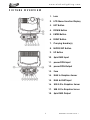
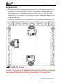
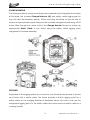
E L A TI ON | EMOTION™ | user manual user manual www.elationlighting.com ©2015 ELATION PROFESSIONAL all rights reserved. Information, specifications, diagrams, images, and instructions herein are subject to change without notice. ELATION PROFESSIONAL logo and identifying product names and numbers herein are trademarks of ELATION PROFESSIONAL. Copyright protection claimed includes all forms and matters of copyrightable materials and information now allowed by statutory or judicial law or hereinafter granted. Product names used in this document may be trademarks or registered trademarks of their respective companies and are hereby acknowledged. All non-ELATION brands and product names are trademarks or registered trademarks of their respective companies. ELATION PROFESSIONAL and all affiliated companies hereby disclaim any and all liabilities for property, equipment, building, and electrical damages, injuries to any persons, and direct or indirect economic loss associated with the use or reliance of any information contained within this document, and/or as a result of the improper, unsafe, insufficient and negligent assembly, installation, rigging, and operation of this product. Elation Professional USA | 6122 S. Eastern Ave. | Los Angeles, CA. 90040 323-582-3322 | 323-832-9142 fax | www.elationlighting.com | [email protected] Elation Professional B.V. | Junostraat 2 | 6468 EW Kerkrade, The Netherlands +31 45 546 85 66 | +31 45 546 85 96 fax | www.elationlighting.eu | [email protected] DOCUMENT VERSION Please check www.elationlighting.com for the latest revision/update of this manual. Date Document Version Fixture Software Version 11/24/15 1 ≥2.0.0U DMX Channel Modes Notes 32 / 54 Initial release. 2 EMOTION™ User Manual Ver. 1 www.elationlighting.com CONTENTS General Information 4 Warranty 6 Safety Instructions 7 General Guidelines 8 Fixture Overview 9 Fixture Installation 10 Fixture Menu 13 EMOTION Overview 16 Graphics Engine Functional Layout 16 Standard Mode / Extended Mode Overview 17 Content Layers and Transistions 18 Layer Display Mode 19 Stock Content or User Content 20 Live Effects 21 Keystone Feature (Standard and Extended Modes) 24 Collage Generator (Extended Mode) 24 Synchronization 27 Fixture Control, Projector Control 28 Content Management Application (CMA) 30 Fixture Software, Firmware and Utilities 38 DMX Channel Functions And Values 42 Error Codes 52 Cleaning and Maintenance 53 Technical Specifications 54 Optional Accessories 55 3 EMOTION™ User Manual Ver. 1 www.elationlighting.com GENERAL INFORMATION INTRODUCTION Congratulations, you have just purchased one of the most innovative digital projector moving head lighting fixtures on the market today! This fixture has been designed to perform reliably for years when the guidelines in this booklet are followed. Please read and understand the instructions in this manual carefully and thoroughly before attempting to operate this unit. These instructions contain important information regarding safety during use and maintenance. UNPACKING Every fixture has been thoroughly tested and has been shipped in perfect operating condition. Carefully check the shipping carton for damage that may have occurred during shipping. If the carton appears to be damaged, carefully inspect your unit for damage and be sure all accessories necessary to operate the unit have arrived intact. In the event damage has been found or parts are missing, please contact our customer support team for further instructions. Please do not return this unit to your dealer without first contacting customer support at the number listed below. Please do not discard the shipping carton in the trash. Please recycle whenever possible. BOX CONTENTS (2) Omega Brackets (1) 5pin DMX Cable (1) powerCON Cable (1) Safety Cable Manual & Warranty Card 4 EMOTION™ User Manual Ver. 1 www.elationlighting.com CUSTOMER SUPPORT Elation Professional® provides a customer support line, to provide set up help and to answer any question should you encounter problems during your set up or initial operation. You may also visit us on the web at www.elationlighting.com for any comments or suggestions. For service related issue please contact Elation Professional®. ELATION SERVICE USA - Monday - Friday 8:00am to 5:00pm PST Voice: 323-582-3322 Fax: 323-832-9142 E-mail: [email protected] ELATION SERVICE EUROPE - Monday - Friday 08:30 to 17:00 CET Voice: +31 45 546 85 30 Fax: +31 45 546 85 96 E-mail: [email protected] WARRANTY REGISTRATION Please complete and mail in the enclosed warranty card or register online: http://www.elationlighting.com/Login.aspx to validate your purchase. All returned service items whether under warranty or not, must be freight pre-paid and accompany a return authorization (R.A.) number. The R.A. number must be clearly written on the outside of the return package. A brief description of the problem as well as the R.A. number must also be written down on a piece of paper and included in the shipping container. If the unit is under warranty, you must provide a copy of your proof of purchase invoice. Items returned without a R.A. number clearly marked on the outside of the package will be refused and returned at customer’s expense. You may obtain a R.A. number by contacting customer support. IMPORTANT NOTICE! There are no user serviceable parts inside this unit. Do not attempt any repairs yourself; doing so will void your manufactures warranty. Damages resulting from modifications to this fixture and/or the disregard of safety and general user instructions found in this user manual void the manufactures warranty and are not subject to any warranty claims and/or repairs. 5 EMOTION™ User Manual Ver. 1 www.elationlighting.com LIMITED WARRANTY A. Elation Professional® hereby warrants, to the original purchaser, Elation Professional® products to be free of manufacturing defects in material and workmanship for a period of two years (730 days), and Elation Professional® product rechargeable batteries to be free of manufacturing defects in material and workmanship for a period of six months (180 days), from the original date of purchase. This warranty excludes discharge lamps and all product accessories. This warranty shall be valid only if the product is purchased within the United States of America, including possessions and territories. It is the owner’s responsibility to establish the date and place of purchase by acceptable evidence, at the time service is sought. B. For warranty service, send the product only to the Elation Professional® factory. All shipping charges must be pre-paid. If the requested repairs or service (including parts replacement) are within the terms of this warranty, Elation Professional® will pay return shipping charges only to a designated point within the United States. If any product is sent, it must be shipped in its original package and packaging material. No accessories should be shipped with the product. If any accessories are shipped with the product, Elation Professional® shall have no liability what so ever for loss and/or or damage to any such accessories, nor for the safe return thereof. C. This warranty is void if the product serial number and/or labels are altered or removed; if the product is modified in any manner which Elation Professional® concludes, after inspection, affects the reliability of the product; if the product has been repaired or serviced by anyone other than the Elation Professional® factory unless prior written authorization was issued to purchaser by Elation Professional®; if the product is damaged because not properly maintained as set forth in the product instructions, guidelines and/or user manual. D. This is not a service contract, and this warranty does not include any maintenance, cleaning or periodic check-up. During the periods as specified above, Elation Professional® will replace defective parts at its expense, and will absorb all expenses for warranty service and repair labor by reason of defects in material or workmanship. The sole responsibility of Elation Professional® under this warranty shall be limited to the repair of the product, or replacement thereof, including parts, at the sole discretion of Elation Professional®. All products covered by this warranty were manufactured after January 1, 1990, and bare identifying marks to that effect. E. Elation Professional® reserves the right to make changes in design and/or performance improvements upon its products without any obligation to include these changes in any products theretofore manufactured. F. No warranty, whether expressed or implied, is given or made with respect to any accessory supplied with the products described above. Except to the extent prohibited by applicable law, all implied warranties made by Elation Professional® in connection with this product, including warranties of merchantability or fitness, are limited in duration to the warranty periods set forth above. And no warranties, whether expressed or implied, including warranties of merchantability or fitness, shall apply to this product after said periods have expired. The consumer’s and/or dealer’s sole remedy shall be such repair or replacement as is expressly provided above; and under no circumstances shall Elation Professional® be liable for any loss and/or damage, direct and/or consequential, arising out of the use of, and/or the inability to use, this product. G. This warranty is the only written warranty applicable to Elation Professional® products and supersedes all prior warranties and written descriptions of warranty terms and conditions heretofore published. 6 EMOTION™ User Manual Ver. 1 www.elationlighting.com SAFETY INSTRUCTIONS This fixture is an extremely sophisticated piece of electronic equipment. To guarantee a smooth operation, it is important to follow the guidelines in this manual. The manufacturer of this device will not accept responsibility for damages resulting from the misuse of this fixture due to the disregard of the information printed in this manual. This device falls under PROTECTION CLASS 1. It’s essential this device be grounded properly. Only qualified personnel should perform all electrical connections. I N D O O R S U S E O N L Y ! DO NOT EXPOSE FIXTURE RAIN AND MOISTURE! UNPLUG POWER BEFORE SERVICING FIXTURE! DO NOT PLUG FIXTURE INTO A DIMMER PACK! NEVER TOUCH FIXTURE DURING OPERATION, AS IT MAY BE HOT! NEVER LOOK DIRECTLY INTO THE LIGHT SOURCE! SENSITIVE PERSONS MAY SUFFER AN EPILEPTIC SHOCK! For proper operation, follow the Installation guidelines described in this manual. Only qualified and certified personnel should perform installation of this fixture and only the original rigging parts (brackets) included with this fixture should be used for installation. Any modifications will void the original manufactures warranty and increase the risk of damage and/or personal injury. Never look directly into the light source of this fixture to prevent risk of injury to your retina, which may induce blindness. Those suffering from E P I L E P S Y should avoid looking directly into the light source of this unit at all times. The fan and air inlets must remain clean and never blocked. Allow approx. 6” (15cm) between this fixture and other devices or a wall for proper cooling. Always disconnect from main power source before performing any type of service and/or cleaning procedure. Only handle the power cord by the plug end, never pull out the plug by tugging the wire portion of the cord. Do not operate this fixture if the power cord has become frayed, crimped and/or damaged. If the power cord is damaged, replace it immediately with a new one of similar power rating. 7 EMOTION™ User Manual Ver. 1 www.elationlighting.com GENERAL GUIDELINES N E V E R O P E N T H I S F I X T U R E W H I L E I N U S E ! During the initial operation of this fixture, a light smoke or smell may emit from the interior of the fixture. This is a normal process and is caused by excess paint in the interior of the casing burning off from the heat associated with the lamp and will decrease gradually over time. This fixture is a professional lighting effect designed for INDOOR / DRY LOCATIONS ONLY on stage, in nightclubs, theatres, etc. Please make sure there are NO FLAMMABLE MATERIALS close to the fixture while operating, to prevent any fire hazard. The fixture must be installed in a location with adequate ventilation, at least 1.5 feet (.5m) from adjacent surfaces. Be sure no air ventilation slots are blocked. DO NOT attempt installation and/or operation without knowledge how to do so. DO NOT permit operation by persons who are not qualified to operate this type of fixture. Most damages are the result of operations by nonprofessionals. Consistent operational breaks may ensure the fixture will function properly for many years to come. DO NOT shake fixture, avoid brute force when installing and/or operating fixture. Always install the fixture with an appropriate safety cable. When installing the fixture in a suspended environment, always use mounting hardware that is no less than M10 x 25 mm, also be sure the hardware is insert in the pre-arranged screw holes in the bracket of the fixture. Use the original packaging and materials to transport the fixture in for service. DO NOT TOUCH the housing bare-hand during its operation. Turn OFF the power and allow approximately 15 minutes for the fixture to cool down before replacing or serving. 8 EMOTION™ User Manual Ver. 1 www.elationlighting.com FIXTURE OVERVIEW 9 1. Lens 2. LCD Menu Function Display 3. LEFT Button 4. DOWN Button 5. ENTER Button 6. RIGHT Button 7. Carrying Handle(s) 8. MODE/ESC Button 9. UP Button 10. 5pin DMX Input 11. powerCON Input 12. powerCON Output 13. Fuse 14. RJ45 to Graphics Server 15. RJ45 Art-NET Input 16. USB 3.0 to Graphics Server 17. USB 3.0 to Graphics Server 18. 5pin DMX Output EMOTION™ User Manual Ver. 1 www.elationlighting.com FIXTURE INSTALLATION FLAMMABLE MATERIAL WARNING Keep fixture at least 5.0 ft (1.5m) away from any flammable materials, decorations, pyrotechnics, etc. ELECTRICAL CONNECTIONS A qualified electrician should be used for all electrical connections and/or installations. CAUTIONS For added protection, mount the fixture in areas outside walking paths, seating areas, or in areas were unauthorized personnel might reach the fixture. Ambient operating temperature range for this fixture is: Temperature 41° to 95°F. (5° to 35°C) | Humidity: 20%–80% (non-condensing) Do not use the fixture under or above this temperature. Before mounting the fixture to any surface, make sure the installation area can hold a minimum point load of 10 times the weight of the fixture. Fixture installation must always be secured with a secondary safety attachment, such as an appropriate safety cable. Never stand directly below the device when mounting, removing or servicing. 10 EMOTION™ User Manual Ver. 1 www.elationlighting.com MOUNTING POINTS Overhead mounting requires extensive experience, including amongst others calculating working load limits, installation material being used, and periodic safety inspection of all installation material and the device. If you lack these qualifications, do not attempt the installation yourself. Improper installation can result in bodily injury. Fixture is fully operational in the specific mounting positions as illustrated below. SAFETY CABLE ALWAYS USE A SAFETY CABLE WHENEVER INSTALLING THIS FIXTURE IN A SUSPENDED ENVIRONMENT TO ENSURE THE FIXTURE WILL NOT DROP IF THE CLAMP FAILS. 11 EMOTION™ User Manual Ver. 1 www.elationlighting.com CLAMP MOUNTING The fixture provides a unique mounting bracket assembly that integrates the bottom of the base, the included Omega Brackets (x2) and safety cable rigging point in one unit (see the illustration below). When mounting this fixture to truss be sure to secure an appropriately rated clamps to the included omega brackets using a M10 screw fitted through the center hole of the Omega Bracket. Be sure to attach an appropriate Safety Cable to the fixture using the safety cable rigging point integrated in the base assembly. SECURING Regardless of the rigging option you choose for your fixture always be sure to secure your fixture with a safety cable. The fixture provides a built-in rigging point for a safety cable on the hanging bracket as illustrated above. Be sure to only use the designated rigging point for the safety cable and never secure a safety cable to a carrying handle. 12 EMOTION™ User Manual Ver. 1 www.elationlighting.com FIXTURE MENU ON-BOARD SYSTEM MENU The fixture comes with an easy to navigate system menu. The next section will detail the functions of each command in the system menu. LCD MENU CONTROL PANEL The control panel (see image below) located on back of the fixture allows you to access the main menu and make all necessary adjustments to the fixture. During normal operation, pressing MODE/ESC button once will access the fixture’s main menu. Once in the main menu you can navigate through the different functions and access the sub-menus with the UP, DOWN, RIGHT, and LEFT buttons. Once you reach a field that requires adjusting, press the ENTER button to activate that field and use the UP and DOWN buttons to adjust the field. Pressing the ENTER button once more will confirm your setting. You may exit the main menu at any time without making any adjustments by pressing the MODE/ESC button. NOTE: To access the LCD Menu Control Display via the internal battery, press and hold the MODE/ESC button for 3 seconds. The LCD Menu Control Display will shut OFF automatically about 1 minute from the last button press. 13 EMOTION™ User Manual Ver. 1 www.elationlighting.com ELATION© EMOTION™ S Y S T E M M E N U Features are subject to change without any prior written notice. MAIN MENU Address SUB MENU OPTIONS / VALUES (Default Settings in BOLD) 001~XXX Time Info. Info DESCRIPTION DMX Address Setting Current Time XXXX (Hours) Fixture Run Time From Power ON Ttl Life Hrs XXXX (Hours) Fixture Total Run Time Last Run Time XXXX (Hours) Clear Fixture Last Run Time Timer PIN Password=XXX Password 038 Clr Last Run ON / OFF Reset Fixture Last Run Time Value Disp NONE, ALL, PAN... DMX Value Display Ethernet IP XXX . XXX . XXX . XXX Ver 2.0.0 U Fixture Ethernet Address Software Version No DMX Mode Close / Hold / Auto Fixture State If No DMX Signal Pan Reverse ON/OFF Pan Reverse Movement Tilt Reverse ON/OFF Tilt Reverse Movement Pan Degree 630/540 Pan Degree Select Encoders ON/OFF Movement Feedback Switch Hibernation OFF, 01M~99M, 15M Stand By Mode Software Version Status On projector Lens Control Always on Off Set DMX Only DMX Only Select Input Art-Net on IP2 Elect Art-Net IP02 Art-Net on IP10 Elect Art-Net IP010 Set Universe 000 - 255 Set Art-Net Universe Disp. Setting Service Setting ResetDefault Shutoff Time 02~60m 05m Display Shut Off Time Flip Reverse ON/OFF Display Reverse 180º Key Lock ON/OFF Key Lock Service PIN Password=XXX Service Password 050 RDM PID Ethernet IP Enter RDM PID XXX . XXX . XXX . XXX ON/OFF Set Fixture IP Address Restore Factory Settings 14 EMOTION™ User Manual Ver. 1 www.elationlighting.com ELATION© EMOTION™ S Y S T E M M E N U Specifications and features are subject to change without any prior written notice. MAIN MENU SUB MENU Mode Set DESCRIPTION All Reset All Motors Pan&Tilt Reset Pan/Tilt Others Reset Others Test Channel PAN …… Test function Manual Control PAN =XXX, ...... Fine Adjustments Calibration Calibration Password Password 050 Home Test OPTIONS / VALUES (Default Settings in BOLD) Standard Mode DMX Channel Modes Extended Mode DMX Control Play Back DMX Control Set To Slave Slave1, Slave2, Slave3 Salve Mode Auto Program Master / Alone Auto Program Prog. Part1 = Program 1~10 (Program 1) Select Prog. Prog. Part2 = Program 1~10 (Program 2) Select Programs To Be Run Prog. Part3 = Program 1~10 (Program 3) Preset Program 1 Edit Prog. Program Test Testing Program : Step 01=SCxxx Program In Loop Program 10 Step 64=SCxxx Save and Exit Pan,Tilt,…… Save and Automatically Return Edit Scenes Scene 001 ~ Scene 250 --Fade Time-- Scenes Input XX~XX --Scene Time-Input By Outside Manual Scenes Edit Stores Scenes via Ext DMX Console Automatic Scenes Recorder Test – Calibration ONLY QUALIFIED TECHNICIANS SHOULD PERFORM THIS FUNCTION. This function allows small adjustments to be made to the fixture to compensate for ware or in the event a sensor has been knocked slightly out of place. Because improper use of this function can result in undesired operation this function has been password protected. The password is 050 and must be entered each time the calibration menu function is entered. Because calibration is an extremely delicate procedure, instructions on performing this action are left out of this manual. For a first time calibrator, please contact our customer support team for step-by-step instructions. 15 EMOTION™ User Manual Ver. 1 www.elationlighting.com EMOTION OVERVIEW The EMOTION™ is a next generation digital light, it contains an embedded projector; a powerful graphics engine and a custom designed Pan/Tilt system. The fixture can be completely controlled via DMX in one of two modes, a Standard Protocol mode to allow a minimum DMX footprint, or a full-featured Extended Protocol mode. The fixture also allows use of standard Ethernet cabling using the ArtNet connection at the base of the fixture. Motion control functions are accessible through the on-board menu system, allowing various configuration options. The graphics server configuration options are accessible through a Content Management application (CMA) running on a network-connected computer. Detailed information about these various components are found in sections of this manual and online at through the Elation website. GRAPHICS ENGINE FUNCTIONAL LAYOUT Below are conceptual block diagrams of the EMOTION™ graphics engine. They are meant to give a graphical representation of how the graphics engine works. Detailed information about each block is found in this manual. CONTENT LAYER 1 16 EMOTION™ User Manual Ver. 1 www.elationlighting.com CONTENT LAYER 2 COMPOSITION STANDARD MODE / EXTENDED MODE OVERVIEW The Emotion Fixture has two distinct control modes that a control board can send commands to it with, a Standard Protocol mode and an Extended Protocol mode. The standard protocol mode allows the most number of fixtures per DMX universe using the fewest number of channels, 32. The extended protocol gives more features, using more channels per fixture, 54. The extended mode adds detailed keystone control, Collage Generator functionality, and fixture synchronization. 17 EMOTION™ User Manual Ver. 1 www.elationlighting.com CONTENT LAYERS AND TRANSITIONS The content layer can be thought of the ‘surface’ in virtual space that the video or gobo image is placed on. Layer 1 is in front of Layer 2; meaning Layer 2 is not visible if there is no transparency in Layer 1. Using the transition parameter will allow layer 1 to be displayed, or layer 2 to be displayed, or a combination of both. (Please see the list below for all transition options.) On a Hog4, they are named as Transition and Transition Mode. Transition Mode (ex. Cross-Fade) is responsible for the ‘type’ of transition. Transition is responsible for the progress. (For Example: 50% means part of Layer 1 is visible and part of Layer 2 is visible) Transition Effects List Crossfade Push Right Push Left Push Down Push Up Reveal Left Reveal Right Reveal Down Reveal Up Reveal Left Down Reveal Right Down Reveal Left Up Reveal Right Up Reveal Circle Out Reveal Circle In Reveal Rectangle Out Reveal Rectangle In Reveal Cross Out Reveal Cross In Pixelate Coarse Pixelate Medium Pixelate Fine Vertical Slats Coarse Vertical Slats Medium Vertical Slats Fine Horizontal Slats Coarse Horizontal Slats Medium Horizontal Slats Fine Swirl 18 DMX Value 0 1 2 3 4 5 6 7 8 9 10 11 12 13 14 15 16 17 18 19 20 21 22 23 24 25 26 27 28 EMOTION™ User Manual Ver. 1 www.elationlighting.com LAYER DISPLAY MODE A layer can display multiple types of content; it can be a still image, or a movie file or a combination of both. The setting that is responsible this is called Media Layer or Media Layer 2 on a Hog4. The list for all possible layer display modes is in the list below. Notice the mode can be as simple as a Gobo, a simple movie file or it can be much more complex combination. One such complex example is using the Gobo as a source for a movie file to be displayed upon. Note in the list that there is mention of “Content Fill” this will scale the content to ensure there are not dark corners that would occur when rotating a rectangular object in a rectangular window. Gobo/Content Control DMX Value Content is taken from Stock Content Gobo 0 Gobo inverted Black to Alpha 1 Gobo Black to Alpha 2 Gobo Negative 3 Gobo Negative Inverted Black to Alpha 4 Gobo Negative Black to Alpha 5 Gobo Black to Alpha 6 Content 7 Content on Gobo 8 Content on Gobo Inverted Black to Alpha 9 Content on Gobo Black to Alpha 10 Content on Negative Gobo 11 Content on Negative Gobo Inverted Black to Alpha 12 Content on Negative Gobo Black to Alpha 13 Gobo Color Distance from Black to Alpha 14 Gobo Inverted Color Distance from Black to Alpha 15 Content Fill 16 Content Fill on Gobo 17 Content Fill on Gobo Inverted Black to Alpha 18 Content Fill on Gobo Black to Alpha 19 Content Fill on Negative Gobo 20 Content Fill on Negative Gobo Inverted Black to Alpha 21 Content Fill on Negative Gobo Black to Alpha 22 Gobo Set Black Transparent 23 19 EMOTION™ User Manual Ver. 1 www.elationlighting.com LAYER DISPLAY MODE [continued] Gobo/Content Control DMX Value Content is taken from User Content Gobo 128 Gobo inverted Black to Alpha 129 Gobo Black to Alpha 130 Gobo Negative 131 Gobo Negative Inverted Black to Alpha 132 Gobo Negative Black to Alpha 133 Gobo Black to Alpha 134 Content 135 Content on Gobo 136 Content on Gobo Inverted Black to Alpha 137 Content on Gobo Black to Alpha 138 Content on Negative Gobo 139 Content on Negative Gobo Inverted Black to Alpha 140 Content on Negative Gobo Black to Alpha 141 Gobo Color Distance from Black to Alpha 142 Gobo Inverted Color Distance from Black to Alpha 143 Content Fill 144 Content Fill on Gobo 145 Content Fill on Gobo Inverted Black to Alpha 146 Content Fill on Gobo Black to Alpha 147 Content Fill on Negative Gobo 148 Content Fill on Negative Gobo Inverted Black to Alpha 149 Content Fill on Negative Gobo Black to Alpha 150 Gobo Set Black Transparent 151 STOCK CONTENT OR USER CONTENT Notice that the above list contains references user content; the Hog4 has a selection to make this choice in the background, without the user needing to keep track of DMX details. (Note: Using the EMOTION™ with other consoles may require a different action) 20 EMOTION™ User Manual Ver. 1 www.elationlighting.com VIDEO FILE – STOCK CONTENT The Emotion fixture ships with 255 pieces of stock video content to be used with the fixture. These files cannot be removed from the fixture, but can be used anywhere when being used with the EMOTION™ fixture. The name in the Hog4 Library for Layer 1 is Media File. The name for Layer 2 is Media File 2. The image below shows Layer 1, displaying file 38 from the stock media folder. USER CONTENT – VIDEO FILE User content can be added to the EMOTION™ fixture. The content type that is required to be .m2v, encoded with all I-Frame for proper functionality of the synchronization system. There are encoding templates available to be used with Adobe Media Encoder. The use of the Content Management Application (CMA) is required to upload user content. (Please see the CMA section of this manual.) Note For Use with Non-Hog4 Control Consoles: The DMX value for this parameter refers to the stock content modes plus 128. For Example: to display “User Video Content”, with no effect- the Layer display mode would be set to 135. To display “User Video Content on Negative Stock Gobo” - the Layer display mode would be set to 139. USER CONTENT – STILL IMAGE User images can be added to the EMOTION™ fixture. The tested content types are have been tested are PNG, JPG and BMP. The resolution is suggested to be 1024x768, without Alpha Channel. The use of the Content Management Application (CMA) is required to upload user content. Please see the CMA section of this manual. LIVE EFFECTS The list on the next page provides the live effects that are available for use in the EMOTION™ fixture. Live effects are applied to Video Content. The effect has one modifier to vary of effect on the original image. (The names in the Hog4 library referring to Layer 1 are Effect1 Mod 1 and Effect 1 Mode. The names referring to Layer 2 are Effect2 Mod 1 and Effect 2 Mode.) LIVE EFFECTS [continued] 21 EMOTION™ User Manual Ver. 1 www.elationlighting.com Content Effects None Swap RGB to GBR Swap RGB to BRG Swap RGB to BGR Swap RGB to RBG Swap RGB to GRB Color Invert Color Invert GBR Color Invert BRG Solarize Solarize 2 Solarize 3 Solarize 4 Edge Detect Edge Detect BW Edge Detect 2 Edge Detect 2 Color Scene Change Detect Rain Drop Faux LED Faux Tile Pixelate Gauss Blur Sharpen Cartoon Color Deconverge Fuzzifier Prism Gaussian Halo Sepia Red Tones Fire Gradient Gray Maker Gray Maker 2 Posterize Black White Negative Art Dot P Horizontal Mirror Tiles Rainbow Cycle 22 DMX Value 0 1 2 3 4 5 6 7 8 9 10 11 12 13 14 15 16 17 18 19 20 21 22 23 24 25 26 27 28 29 30 31 32 33 34 35 36 37 38 39 40 EMOTION™ User Manual Ver. 1 www.elationlighting.com GOBO AND GOBO ROTATE The Gobo parameter recalls the stock images to be used in the various layer modes. The Gobo Rotate parameter mimics the look of an actual rotating gobo wheel. The effect can be static, or a continuous. The rotate function is active for gobo images as well as Video Content. (The names in the Hog Library are Gobo, Gobo <>, Gobo2, and Gobo 2<>.) BACKGROUND COLOR AND COLOR EFFECT The EMOTION™ fixture can have a background color applied or even a dynamic background color effect shown in the output. In addition, when calling up a fixture, for example 1 @ full, the background is set to full ‘white’ by default in the Hog4 library. Note: This behavior is to aide programming by mimicking a conventional fixture, but at times this background is seen when modifying layers. To ‘mute’ this effect – set the color channels to Red 0, Green 0, and Blue 0. (These parameter channels are oddly named CMY on a Hog4) The chart below details all parameters of the background color and color effect feature. (The names in the Hog Library are Color FX to choose the background effect, the Cyan, Magenta, and Yellow naming is used for Modifiers 1,2 and 3 respectfully) DMX 0 1 2 3 4 5 6 7 8 9 10 11 12 13 14 15 16 17 18 19 20 Background Color Effects Cyan Magenta Yellow Red Cycle Green Cycle Blue Cycle Red Green Cycle Red Blue Cycle Green Blue Cycle Red Green Blue Cycle Gradient Red Gradient Red 2 Gradient Green Gradient Green 2 Gradient Blue Gradient Blue 2 Gradient Red Green Gradient Red Delta Gradient Red Delta 2 Gradient Green Delta Gradient Green Delta 2 Gradient Blue Delta Gradient Blue Delta 2 Description (M1, 2, 3 = Modifier 1, 2, 3) Cyan-Set Cyan; Magenta-Set Magenta; Yellow-Set Yellow M1-Red Speed. M2-Green Level. M3-Blue Level. M1-Red Level. M2-Green Speed. M3-Blue Level. M1-Red Level. M2-Green Level. M3-Blue Speed. M1-Red Speed. M2-Green Speed. M3-Blue Level. M1-Red speed. M2-Green Level. M3-Blue Speed. M1-Red level. M2-Green Speed. M3-Blue Speed. M1-Red speed. M2-Green Speed. M3-Blue Speed. M1-Red X Position. M2-Red Y Position. M3-Green Blue Multiplier. M1-Red X Position. M2-Red Y Position. M3-Green Blue Multiplier. M1-Green X Position. M2-Green Y Position. M3-Red Blue Multiplier. M1-Green X Position. M2-Green Y Position. M3-Red Blue Multiplier. M1-Blue X Position. M2-Blue Y Position. M3-Red Green Multiplier. M1-Blue X Position. M2-Blue Y Position. M3-Red Green Multiplier. M1-Red Multiplier. M2-Green Multiplier. M3-Rotation. M1-Red Multiplier. M2-Green Multiplier. M3-Blue Multiplier. M1-Red Multiplier. M2-Green Multiplier. M3-Blue Multiplier. M1-Red Multiplier. M2-Green Multiplier. M3-Blue Multiplier. M1-Red Multiplier. M2-Green Multiplier. M3-Blue Multiplier. M1-Red Multiplier. M2-Green Multiplier. M3-Blue Multiplier. M1-Red Multiplier. M2-Green Multiplier. M3-Blue Multiplier. 23 EMOTION™ User Manual Ver. 1 www.elationlighting.com KEYSTONE FEATURE (STANDARD MODE) The keystone feature available in the Standard Mode of the protocol gives a basic modification to account for minor projection angle variations. There are 2 parameters give for this control, Keystone X Ratio and Keystone Y Ratio. When modifying these parameters, the image is rotated around their X axis or Y axis respectively, this gives a basic modification. KEYSTONE FEATURE (EXTENDED MODE) The keystone feature available in the Extended Mode of the protocol uses 4 corner points, with an X/Y position control at each corner. The 8 control channels give detailed control over keystone modification. These parameters allow independent X, Y control of the 4 corners. In addition to the corner position modification, the linearity of the image can be adjusted as well. This adjustment allows for warping the image when projecting at shallow angles. These warping controls are labeled Keystone X Ratio and Keystone Y Ratio. The images below show the Hog4 slot toolbar layout. COLLAGE GENERATOR (EXTENDED MODE) The Collage Generator system is part of the graphics engine that allows multiple devices to work together to create a larger, virtually seamless image. The graphics engines of multiple servers can work together to create this much larger image. There are various modes that the Collage Generator can work, Standard Collage, Multi-Pane Collage, Standard Wrap, and Multi-Pane Wrap, all with various blending options. These various modes will use content differently to create the final full image. Standard Collage In the Standard Collage options, the content is automatically 'sliced' into cell segments by the graphics engine when you define the array size. This yields good results in situations where moderate output resolution is suitable. Be aware, each graphic output is using a full resolution image file and only projecting the needed portion of the image, which can impact performance. Multi-Pane Collage In the Multi-Pane Collage options, the content is NOT sliced by the server and must be sliced before importing. This situation allows a much higher resolution output of the total collage. Using Multi-Pane Collage gives you the option to use video files that match the resolution of the display devices exactly. Wrap In the Wrap option, the blending area of the first and last image are repeated on the edge, so that they can be overlapped when build a cylindrical projection. This is required for a virtually seam-less output. Multi-Pane example, if you have four Emotion fixtures using a 4-part Multi-Pane Collage with individual 1024x768 video files, the resulting collage resolution will be much higher. In standard collage modes, a single file is divided by the number of parts in the collage. This method may not be visually acceptable on a large screen. 24 EMOTION™ User Manual Ver. 1 www.elationlighting.com COLLAGE TYPE The list below provides the possible Collage Type settings. DMX Value Action 1 Standard Collage divides content for projection onto a flat surface Standard Collage with 360° wrap divides the content into an array and 2 edge blending for projection onto a 360° surface Multi-Pane Collage pre-configures the content into cells that are then 3 arranged into an array for projection onto a flat surface Multi-Pane Collage with 360° wrap pre-configures the content into cells 4 that are then arranged into an array for projection onto a 360° surface. COLLAGE CELL AND COLLAGE CELL SELECTION The Collage Cell parameter tells the Collage Generator how many total cells are in a collage. The layout of the grid is also selected at this time, for example a 2x1 grid is different from a 1x2 grid. DMX Values of 126-255 are reserved and default to no collage. (See the below Collage Cell Chart for more details) The Collage Cell Selection parameter determines which cell a particular EMOTION™ fixture will display. DMX values 0 up to 127 are used to step through the grid pattern determined by the Collage Cell parameter. DMX values outside the valid range default to the upper left corner of the grid. COLLAGE CELL DMX Value 1 2 3 4 5 6 7 8 9 10 11 12 13 14 15 16 17 18 19 20 21 22 23 24 25 126 127 Array (W x H) 2x1 1x2 2x2 3x1 1x3 3x2 2x3 3x3 4x1 1x4 4x2 2x4 4x3 3x4 4x4 5x1 1x5 5x2 2x5 5x3 3x5 5x4 4x5 5x5 6x1 16 x 7 16 x 8 DMX Value 26 27 28 29 30 31 32 33 34 35 36 37 38 39 40 41 42 43 44 45 46 47 48 49 50 Array (W x H) 1x6 6x2 2x6 6x3 3x6 6x4 4x6 6x5 5x6 6x6 7x1 1x7 7x2 2x7 7x3 3x7 7x4 4x7 7x5 5x7 7x6 6x7 7x7 8x1 1x8 DMX Value 51 52 53 54 55 56 57 58 59 60 61 62 63 64 65 66 67 68 69 70 71 72 73 74 75 Array (W x H) 8x2 2x8 8x3 3x8 8x4 4x8 8x5 5x8 8x6 6x8 8x7 7x8 8x8 9x1 9x2 9x3 9x4 9x5 9x6 9x7 9x8 10 x 1 10 x 2 10 x 3 10 x 4 25 DMX Value 76 77 78 79 80 81 82 83 84 85 86 87 88 89 90 91 92 93 94 95 96 97 98 99 100 Array (W x H) 10 x 5 10 x 6 10 x 7 10 x 8 11 x 1 11 x 2 11 x 3 11 x 4 11 x 5 11 x 6 11 x 7 11 x 8 12 x 1 12 x 2 12 x 3 12 x 4 12 x 5 12 x 6 12 x 7 12 x 8 13 x 1 13 x 2 13 x 3 13 x 4 13 x 5 DMX Value 101 102 103 104 105 106 107 108 109 110 111 112 113 114 115 116 117 118 119 120 121 122 123 124 125 Array (W x H) 13 x 6 13 x 7 13 x 8 14 x 1 14 x 2 14 x 3 14 x 4 14 x 5 14 x 6 14 x 7 14 x 8 15 x 1 15 x 2 15 x 3 15 x 4 15 x 5 15 x 6 15 x 7 15 x 8 16 x 1 16 x 2 16 x 3 16 x 4 16 x 5 16 x 6 EMOTION™ User Manual Ver. 1 www.elationlighting.com COLLAGE CELL SELECTION COLLAGE EDGE BLENDING Variable Edge Blending controls are used with the Collage Generator controls to allow for on-the-fly adjustment of blend overlap between projectors. These controls allow more flexibility for sizing a collage to a given screen or projection surface, as well as smoother blending if wider blend regions are used. Horizontal and Vertical blend regions can be controlled independently of one another. The Variable Edge Blend Horizontal and Vertical parameters allow 16-bit control of the horizontal blend region width from 0% (hard edge) up to 50% of the image size. COLLAGE EDGE BLENDING CURVE ADJUSTMENT The Edge Curve Adjustment lets you select from a variety of detailed methods to modify the blending curve to control the overlap of the adjacent projections. These modifications should only take place after all other modifications are complete. They give the final adjustment to the overlapped region to make the overlapped edge virtually seamless. DMX Value 0 1-33 34 35-63 64-95 96 97-127 Curve Type and Range Standard Color Blend Curve – No Adjustment Standard Color Blend Curve w/Intensity Reduction (1 = Max Reduction) Standard Color Blend Curve – No Adjustment Standard Color Blend Curve w/Intensity Addition (63 = Max Addition) Grey Scale Blend Curve w/Intensity Reduction (64 = Max Reduction) Grey Scale Blend Curve – No Adjustment Grey Scale Blend Curve w/Intensity Addition (127 = Max Addition) 26 EMOTION™ User Manual Ver. 1 www.elationlighting.com COLLAGE EDGE CONTROL / ALIGNMENT PATTERN OUTPUT During Collage setup, it is helpful to view a grid or other technical images to help the process of aligning each individual EMOTION™ fixture to its portion of the total collage. There are six alignment patterns available. Each pattern has a different use and is helpful in different ways. Generally speaking, using the “Alignment Pattern with Normal Blending” (value 3) or “Alignment Pattern with No Blending ” (value 5) are the most used. Below is the full list of technical images available to aid the alignment of the cell to the full collage. DMX Value 0 1 2 3 4 5 6 Action Graphics Out. Normal Blending Per Selected Blend Adjustment Graphics Out. Blend Area Defaulted To Black Graphics Out. Blend Area Shown With No Blending Applied Alignment Pattern Out. Normal Blending Per Selected Blend Adjustment Alignment Pattern Out. Blend Area Defaulted To Black Alignment Pattern Out. Blend Area Shown With No Blending Applied Grid Cell Selection Shown Over Graphics Output SYNCHRONIZATION Network Synchronization allows for certain functions of the fixture to be synchronized over an Ethernet network, accessible through the Graphics server port. This can be very useful when using the Collage Generator to ensure a seamless image across multiple fixtures. Network Synchronization is accomplished using a reference fixture that sends information about its movie time. The sync information is transmitted via an Ethernet network to all listening server. The other listening servers, or slave servers use this information to set their movie times to match the reference server. This process is based on a global time clock using time offsets. Network Synchronization is not Control Mirroring. With Control Mirroring, the fixtures are controlled with the same source, but do not communicate with each other. At times this method yields acceptable results, but to properly use Network Synchronization, all attached servers must have a unique control source. 27 EMOTION™ User Manual Ver. 1 www.elationlighting.com NETWORK SYNCHRONIZATION REQUIREMENTS In order for Network Synchronization to function properly, there are a few requirements that must be adhered to in the set-up of the fixtures: All of the servers must be linked on an Ethernet network through the graphics server port. This network must be configured on a DHCP network and the router must have sufficient bandwidth to handle all connected fixtures. Low cost 10/100 wireless routers may not work properly; higher quality 100/1000 routers are generally preferred. The Fixture ID for each fixture on the network must be unique. The Fixture ID is used to assign the master and slave servers. Having multiple media servers with the same Fixture ID will cause Network Synchronization to fail. Fixture ID is set via the CMA. All video content to be used in a Synchronization scenario MUST adhere to the encoding requirements for encoding custom content. If the content is not encoded correctly Network Synchronization will not function. Specifically all image information must be present at all frame locations. Highly compressed video does not contain all image information in every frame, but only the changes from a key-frame previously encountered in playback. NETWORK SYNCHRONIZATION CAPABILITIES The system is designed to help keep the movie playback time relatively in sync, as perceived. The system is not designed to frame lock or gen-lock, these features will not be supported in the Emotion fixture. Synchronization is used between multiple servers for Collage applications, or other perceived playback applications. NETWORK - ENABLE To enable network sync, all fixtures must be on an Ethernet network, have an IP assigned by a DHCP, and have a unique ID number. Sync is activated by changing the Sync Control channel from zero to the fixture ID that is meant to be the sync target. For example, 4 fixtures connected have fixture ID’s of 11, 12, 13, 14. The sync master is meant to be the 4th fixture, which in this example would be 14. Setting the sync value of all fixtures to 14 will tell the fixtures to listen to the 4th fixture. Note that there is no issue setting the master to sync to its self. By selecting all fixtures in the sync group, and setting them to the same value eases programming and minimizes mistakes. FIXTURE CONTROL, PROJECTOR CONTROL The fixture control channel is used to set various functions and features of the EMOTION™ fixture. When there is not a specific command needed, the control channel must be set to Idle or Safe (Channel 7, Value of 0). Please note, leaving a control channel active can impact performance, as the projector can be constantly responding to command. For example, if the projector is commanded to flip, there will be the initial change, and every second after; the projector will attempt to change again. Please leave the control channel at Idle when not intending to make a change. 28 EMOTION™ User Manual Ver. 1 www.elationlighting.com FIXTURE IDLE This is the default value, and can be thought of as the ‘no command’ mode. Please use allow the control channel to remain at this value when not in use (Channel 7, Value of 0) FIXTURE SHUTDOWN This command is meant to turn-off the motion system. Note the lamp off must be sent in a separate command. It is good practice to shutdown the fixture and lamp before removing power – please allow 5 minutes for the projector lamp to cool before removing power. Sending the Home All command will ‘wake up’ a fixture in shutdown mode. HOME ALL This function is used to reset the Pan and Tilt position sensors and allow the system to start from a known position. Use this command when the Pan and Tilt is not responding correctly, or if the fixture has been impacted and no longer pointing in the correct direction. LAMP STRIKE This command is used to turn-on the projector lamp. The projector has in-built protection to allow the lamp to strike only when cool. LAMP DOUSE This command is used to turn-off the projector lamp. The projector will have a notification screen when this command is received. This is useful for ensuring the projector is responding as intended. PROJECTOR ORIENTATION This command is meant to change the orientation of the projected image. For example if the projector is hung inverted, the projector can ‘flip’ its output so that images remain upright. There is also the option to front-project or rear-project the image. 29 EMOTION™ User Manual Ver. 1 www.elationlighting.com CONTENT MANAGEMENT APPLICATION (CMA) The CMA is a standalone application that is installed and run from a networked PC. Typically the CMA is installed on a laptop and is available when the fixtures are in use. The CMA is also responsible for all graphics engine management functions as well as managing user content. Graphics engine software updates are handled through the CMA as well. The CMA communicates with the Emotion graphics engine through the Ethernet port labeled “Graphics Server.” 30 EMOTION™ User Manual Ver. 1 www.elationlighting.com INSTALLATION OF THE CMA Installing the CMA is a very similar to all other applications installed on a PC. The PC that is being used to run the CMA must meet minimum requirements for Windows 7® and above. The installation steps are listed below. Before You Begin: Download the CMA installer from www.elationlighting.com. Double click on the downloaded file, it will likely be titled eMotion_CMA_x-x-x-x.msi (where the ‘x’ would be the version number) The Windows installer process begins after double-clicking. Press ‘Next’ after being greeted by the setup wizard You must accept the License Agreement, and Press ‘Next’ to continue. 31 EMOTION™ User Manual Ver. 1 www.elationlighting.com INSTALLATION OF THE CMA [continued] If you would like to make a change to the installation directory, you can do that now. It is not recommended unless there is a specific need. Check the box if you would like a Desktop Shortcut added after installation, this is recommended to ease use 32 EMOTION™ User Manual Ver. 1 www.elationlighting.com INSTALLATION OF THE CMA [continued] Press ‘Next’ to confirm no changes are needed, then the installation process will begin. A dialog box may appear if there are other applications open when you are trying to install, choose option that best fits your need. It is recommended to reboot after installation anyways. 33 EMOTION™ User Manual Ver. 1 www.elationlighting.com INSTALLATION OF THE CMA [continued] Press ‘Finish’ to end the installation process. 34 EMOTION™ User Manual Ver. 1 www.elationlighting.com FUNCTIONAL LAYOUT OF THE CMA The below image shows the functional layout of the CMA, fixtures attached on the same network, using the graphics engine Ethernet port, which will be auto-discovered and displayed below. It is important to note that there is no direct control of the graphics engine IP address. If this functionality is needed, please use a router with a DHCP server set for your specific use. 35 EMOTION™ User Manual Ver. 1 www.elationlighting.com GRAPHICS SERVER CONFIRGURATION Select the EMOTION™ to be viewed in the left-side tree view. Information will be displayed in the right panel. Fixture ID – User definable number, used for the synchronization system. If sync is to be used, all fixtures must have a unique Fixture ID when they are networked using their Graphics server Ethernet connector. Identify – Check this box, and press ‘Apply’. The graphics engine will strobe white, this is used to locate fixtures Server Name – User definable name, used for friendly organization in the CMA. Video Selftest / Media File – A utility method to force output of the graphics engine, this function is useful for troubleshooting. Two preset methods are also included in the Self-Test feature. SDI Format – (Accessory) a configuration option for the attached Ultra Studio SDI USB3 capture device. Recommended to use ‘AUTO’ Version Information – Multiple software versions installed in the fixture. 36 EMOTION™ User Manual Ver. 1 www.elationlighting.com VIDEO FILE – USER CONTENT ADDITION Please Note: Before adding content, video files must be properly encoded for proper playback. Still images must be properly formatted for proper playback as well. Please use the encoding template for proper video playback. Content will be scanned before being imported, any content that is deemed unacceptable will not be added to the fixture – this is to maintain reliability of the fixture. Also, the use of ‘spaces’ in a file name is not allowed, this will be handled automatically upon import. To add User Content navigate to the User Media / User Content folder in the tree view. Content files can be added from a Windows 7® computer via Drag-drop or Cut-Paste method. Once the file is transferred to the graphics engine, a DMX address must be added. This can be accomplished by, right clicking on a file and pressing “Auto-Set DMX” will apply the next available DMX value. 37 EMOTION™ User Manual Ver. 1 www.elationlighting.com FIXTURE SOFTWARE, FIRMWARE AND UTILITIES EMOTION™ GRAPHICS ENGINE SOFTWARE UPDATE The software is used by the embedded graphics engine can be updated remotely, this method use the graphics server Ethernet connection. Before updating software, be sure to power on, allow the Emotion fixture to find all network devices, and finish startup requirements. This process generally takes up to a minute- please do not start a software update process within 1 minute of powering on an EMOTION™ fixture. To Update Software: Be sure the fixture is seen in the fixture tree Select the fixture in the right panel From the menu bar, choose ‘Servers’ A pop up window will appear, prompting for the location of the .BDL file to send to the graphics engine. Detailed information will be contained with the .BDL file, highlighting software changes. 38 EMOTION™ User Manual Ver. 1 www.elationlighting.com EMOTION™ GRAPHICS ENGINE SOFTWARE UPDATE [continued] Follow on-screen prompts to update software. (This dialog box is asking for the location of the .BDL file that was downloaded) EMOTION™ MOTION SYSTEM FIRMWARE UPDATE The EMOTION™ fixture has a separate procedure to update the firmware of the motion system. This update process requires the use of a separate loading device. Please contact support for more information, and reference the procedures that are enclosed with the firmware device. EMOTION™ GRAPHICS SYSTEM RESTORE – USB STICK At times there are system changes that affect the foundation of the graphics engine. These changes cannot be accomplished through the update process mentioned above. By using a system image and a bootable USB stick, the System Restore method can reset the entire system to a factory default state. Process Outline: Download a system restore image from the support website. Prepare the USB stick System restore. Place the USB stick in the fixture to restore and boot from it by pressing F10. Launch the System Restore process. Follow the onscreen prompts: o Partial restore: User content will be unaffected o Full restore: User content will be removed o Confirm, and process will complete. Remove USB when prompted by green text at next restart. Process will complete automatically. 39 EMOTION™ User Manual Ver. 1 www.elationlighting.com DOWNLOAD SYSTEM IMAGE The EMOTION™ fixture graphics system image is available on the support website. Please download this file and place it on the desktop for easy access. PREPARE USB STICK A USB stick is required; it must be at least 8GB. It is suggested to be USB3.0 to speed the process. The USB stick is easily prepared by using a helper application called Rufus. (https://rufus.akeo.ie/) Please see the tech bulletin for detailed instruction on how to use Rufus. BOOT TO USB STICK The graphics server must be reset to access the system restore, it is advised to power on the Emotion fixture and allow it to start fully. Once the system is fully up and running (approx. 1 min after power on) be sure to open the shutter of the fixture. This can be from a control board or by the internal menu system found under manual control of intensity. After the shutter is open, insert the USB stick into one of the USB ports, and place a keyboard into the other port. Press and hold the graphics system reset button for approx. 5seconds. Release the reset switch and begin tapping F10 on the keyboard (approx. 3 presses/second) you will see the Elation boot screen being shown from the projector. You will see the projector flash a few times while booting; it is searching for the output source. Once you see the boot device selection screen (shown below) you can stop pressing F10. 40 EMOTION™ User Manual Ver. 1 www.elationlighting.com LAUNCH THE SYSTEM RESTORE PROCESS Use the keyboard to navigate to the line that says “USB” (second line in SCREEN image on the previous page) Press enter and continue pressing enter until you see the Windows Fish (shown below), at which point stop pressing enter. You have now successfully booted to the USB stick. FOLLOW THE ON-SCREEN PROMPTS Once the system restore process has begun, please follow the on-screen instructions to choose a partial restore or a full restore. A partial restore will remove and reinstall all graphics engine software. A full restore will remove graphics engine software and all user content. Both methods cannot be undone. PROCESS CONTINUES AND ENDS AUTOMATICALLY After choosing the on-screen confirmation to being the system restore, the process will copy needed files over to the graphics server, and make all necessary changes. The process will prompt the removal of the USB stick. This is highlighted by green text on screen saying the server will restart automatically. After the restart there are various setup items that will be completed. Windows will notify of settings being applied and may restart. Please wait for approx. 10 minutes to allow all the window processes to complete, and the server complete. At this time, it may be necessary to power cycle the entire fixture, to ensure that proper motion system and graphics system communications align. EMOTION™ GRAPHICS SYSTEM RESTORE – UTILITY MENU / USER MENU / USER CONTENT DELETION There is a helper utility on the USB stick to aid the recovery of a fixture in the event corrupted content is added by mistake. To access this utility, access the system restore USB stick via the method described above. (Reboot, F10, choose USB, Press enter for the Betafish) After booting to the USB stick, press the “Utilities” button, the hard drive will be scanned and there will be one option to delete all user content. Press “Confirm” and the process ends quickly and automatically. Exit and remove the USB stick, the fixture should start normally. 41 EMOTION™ User Manual Ver. 1 www.elationlighting.com D M X P R O T O C O L - S T A N D A R D [32 CHANNELS] Channel Construct 1 2 3 4 Pan Pan Tilt Tilt 5 Zoom 6 Focus 7 Control [Indexed] Description Decimal Decimal Percent Percent Low High Low High Hex Low Hex High Pan Coarse Pan Fine Tilt Coarse Tilt Fine 0 255 0% 100% 00h FFh 0 255 0% 100% 00h FFh 0 255 0% 100% 00h FFh 0 255 0% 100% 00h FFh 0 0% 00h Digital Zoom Smallest 128 50% 80h Digital Zoom Largest 129 51% 81h Optical Zoom Smallest 255 100% FFh Optical Zoom Largest 0 0% 00h Focus In 255 100% FFh Focus Out The Control channel should not be crossfaded. No shutter channel requirement. Safe (Normal Operation) 0 3 0% 1% 00h 03h TBD 4 27 2% 11% 04h 1Bh Shutter channel to 0 for access to the following commands. Display Off 28 31 11% 12% 1Ch 1Fh (Send 20 Packets) Display On 32 35 13% 14% 20h 23h (Send 20 Packets) TBD 36 63 14% 25% 24h 3Fh Home All (Send 20 Packets) 64 67 25% 26% 40h 43h Reserved 68 71 27% 28% 44h 47h Lamp On 72 75 28% 29% 48h 4Bh Lamp Off 76 79 30% 31% 4Ch 4Fh Shutdown 80 83 31% 33% 50h 53h (Send 80 Packets) Graphic System Reset 84 87 33% 34% 54h 57h Lamp Brightness 88 91 35% 36% 58h 5Bh Lamp Eco 92 95 36% 37% 5Ch 5Fh Reserved 96 107 38% 42% 60h 6Bh Projector Floor Orientation 108 111 42% 44% 6Ch 6Fh Projector Ceiling 112 115 44% 45% 70h 73h Orientation Projector Front Orientation 116 119 45% 47% 74h 77h Projector Rear Orientation 120 123 47% 48% 78h 7Bh TBD 124 247 49% 97% 7Ch F7h DMX HUD in Blue 248 97% 0% F8h 00h DMX HUD in Green 249 98% 0% F9h 00h DMX HUD in Red 250 98% 0% FAh 00h DMX HUD in White 251 98% 0% FBh 00h General HUD in Blue 252 99% 0% FCh 00h General HUD in Green 253 99% 0% FDh 00h General HUD in Red 254 100% 0% FEh 00h General HUD in White 255 100% 0% FFh 00h 42 EMOTION™ User Manual Ver. 1 Default 128 0 128 0 192 128 0 www.elationlighting.com Channel Construct Description Decimal Decimal Percent Percent Low High Low High Hex Low Hex High Default 00h 00h 00h 55h A8h FFh 00h FFh 00h FFh 00h FFh 00h FFh FFh 00h 54h A7h FFh FFh 0 8 Intensity 9 Strobe [Note 5] 10 Iris 11 Cyan (Mod 1) 12 Magenta (Mod 2) 13 Yellow (Mod 3) 14 15 16 Color Effect [Note 1] Gobo 1 Control Gobo 1 Control Fine TBD TBD TBD 0 0 0 255 255 255 0% 0% 0% 100% 100% 100% 00h 00h 00h FFh FFh FFh 17 Gobo 1 TBD 0 255 0% 100% 00h FFh 0 128 0 0 18 Content 1 Control [Note 2] TBD 0 255 0% 100% 00h FFh 0 Content 1 [Note 7] No Selection Select Content 0 1 255 0% 0% 100% 00h 01h FFh 0 20 21 22 23 Content 1 Effect [Note 3] Content 1 Effect Speed Gobo2 Control Gobo 2 Control Fine TBD TBD TBD TBD 0 0 0 0 255 255 255 255 0% 0% 0% 0% 100% 100% 100% 100% 00h 00h 00h 00h FFh FFh FFh FFh 0 0 128 0 24 Gobo 2 TBD 0 255 0% 100% 00h FFh 0 25 Content 2 Control [Note 2] TBD No Selection 0 0 255 0% 0% 100% 00h 00h FFh Select Content 1 255 0% 100% 01h FFh 19 26 Content 2 [Note 7] Normal Dimming Open Periodic Synchronous Random Random Random Open Closed Open Open Full Saturation Open Full Saturation Open Full Saturation 0 0 0 85 168 255 0 255 0 255 0 255 0 255 255 0 84 167 255 255 0% 0% 0% 33% 66% 100% 0% 100% 100% 0% 100% 0% 100% 0% 100% 0% 33% 65% 100% 100% 255 0 0 0 27 28 29 Content 2 Effect [Note 3] Content 2 Effect Speed Transition (T-‐Handle) TBD TBD Transition Between Layers 0 0 0 255 255 255 0% 0% 0% 100% 100% 100% 00h 00h 00h FFh FFh FFh 30 31 32 Transition Effect [Note 4] Keystone Horizontal Keystone Vertical TBD TBD TBD 0 0 0 255 255 255 0% 0% 0% 100% 100% 100% 00h 00h 00h FFh FFh FFh 43 0 EMOTION™ User Manual Ver. 1 0 0 0 0 128 0 128 128 www.elationlighting.com D M X P R O T O C O L - E X T E N D E D [54 CHANNELS] Channel Construct 1 2 3 4 Pan Pan Tilt Tilt 5 Zoom 6 Focus 7 Control [Indexed] Description Decimal Decimal Percent Percent Low High Low High Hex Low Hex High Pan Coarse Pan Fine Tilt Coarse Tilt Fine 0 255 0% 100% 00h FFh 0 255 0% 100% 00h FFh 0 255 0% 100% 00h FFh 0 255 0% 100% 00h FFh 0 0% 00h Digital Zoom Smallest 128 50% 80h Digital Zoom Largest 129 51% 81h Optical Zoom Smallest 255 100% FFh Optical Zoom Largest 0 0% 00h Focus In 255 100% FFh Focus Out The Control channel should not be crossfaded. No shutter channel requirement. Safe (Normal Operation) 0 3 0% 1% 00h 03h TBD 4 27 2% 11% 04h 1Bh Shutter channel to 0 for access to the following commands. Display Off 28 31 11% 12% 1Ch 1Fh (Send 20 Packets) Display On 32 35 13% 14% 20h 23h (Send 20 Packets) TBD 36 63 14% 25% 24h 3Fh Home All (Send 20 Packets) 64 67 25% 26% 40h 43h Reserved 68 71 27% 28% 44h 47h Lamp On 72 75 28% 29% 48h 4Bh Lamp Off 76 79 30% 31% 4Ch 4Fh Shutdown 80 83 31% 33% 50h 53h (Send 80 Packets) Graphic System Reset 84 87 33% 34% 54h 57h Lamp Brightness 88 91 35% 36% 58h 5Bh Lamp Eco 92 95 36% 37% 5Ch 5Fh Reserved 96 107 38% 42% 60h 6Bh Projector Floor Orientation 108 111 42% 44% 6Ch 6Fh Projector Ceiling 112 115 44% 45% 70h 73h Orientation Projector Front Orientation 116 119 45% 47% 74h 77h Projector Rear Orientation 120 123 47% 48% 78h 7Bh TBD 124 247 49% 97% 7Ch F7h DMX HUD in Blue 248 97% 0% F8h 00h DMX HUD in Green 249 98% 0% F9h 00h DMX HUD in Red 250 98% 0% FAh 00h DMX HUD in White 251 98% 0% FBh 00h General HUD in Blue 252 99% 0% FCh 00h General HUD in Green 253 99% 0% FDh 00h General HUD in Red 254 100% 0% FEh 00h General HUD in White 255 100% 0% FFh 00h 44 EMOTION™ User Manual Ver. 1 Default 128 0 128 0 192 128 0 www.elationlighting.com Channel Construct Description Decimal Low 0 0 0 85 168 255 0 255 0 255 0 255 0 255 Decimal High 255 0 84 167 255 255 Percent Low 0% 0% 0% 33% 66% 100% 0% 100% 100% 0% 100% 0% 100% 0% Percent Hex High Low 100% 00h 0% 00h 33% 00h 65% 55h 100% A8h 100% FFh 00h FFh 00h FFh 00h FFh 00h FFh Hex High FFh 00h 54h A7h FFh FFh Default 8 Intensity 9 Strobe [Note 5] 10 Iris 11 Cyan (Mod 1) 12 Magenta (Mod 2) 13 Yellow (Mod 3) 14 Color Effect [Note 1] TBD 0 255 0% 100% 00h FFh 0 15 16 17 Gobo 1 Control Gobo 1 Control Fine Gobo 1 TBD TBD TBD 0 0 0 255 255 255 0% 0% 0% 100% 100% 100% 00h 00h 00h FFh FFh FFh 128 0 0 18 Content 1 Control [Note 2] TBD 0 255 0% 100% 00h FFh 0 No Selection Select Content 0 1 0 0 255 255 255 0% 0% 0% 0% 100% 100% 100% 00h 01h 00h 00h FFh FFh FFh 128 128 TBD 0 255 0% 100% 00h FFh 0 TBD TBD TBD TBD 0 0 0 0 255 255 255 255 0% 0% 0% 0% 100% 100% 100% 100% 00h 00h 00h 00h FFh FFh FFh FFh 0 128 0 0 TBD 0 255 0% 100% 00h FFh 0 19 20 21 22 23 24 25 26 Content 1 [Note 7] Content 1 Brightness Content 1 Contrast Content 1 Effect [Note 3] Content 1 Effect Speed Gobo2 Control Gobo 2 Control Fine Gobo 2 Normal Dimming Open Periodic Synchronous Random Random Random Open Closed Open Open Full Saturation Open Full Saturation Open Full Saturation 0 0 255 0 0 0 0 27 Content 2 Control [Note 2] 28 Content 2 [Note 7] No Selection 0 0% 00h Select Content 1 255 0% 100% 01h FFh 29 Content 2 Brightness 0 255 0% 100% 00h FFh 128 30 Content 2 Contrast 0 255 0% 100% 00h FFh 128 31 Content 2 Effect [Note 3] TBD 0 255 0% 100% 00h FFh 0 32 33 Content 2 Effect Speed Transition (T-‐Handle) TBD Transition Between Layers 0 0 255 255 0% 0% 100% 100% 00h 00h FFh FFh 0 128 34 Transition Effect [Note 4] TBD 0 255 0% 100% 00h FFh 0 45 EMOTION™ User Manual Ver. 1 0 www.elationlighting.com Channel Construct Description Decimal Decimal Percent Percent Low High Low High Hex Low Hex High Default 35 Collage Type [Indexed] College Type Selection 0 255 0% 100% 00h FFh 0 36 Collage Configuration [Indexed] College Grid Size Selection 0 255 0% 100% 00h FFh 0 37 Collage Cell [Indexed] College Cell Selection 0 255 0% 100% 00h FFh 0 38 Collage Blend Adjust [Indexed] College Blend Region Adjust 0 255 0% 100% 00h FFh 0 39 Collage Edge Control Alignment Pattern [Indexed] Blend ON/OFF, Alignment Pattern 0 255 0% 100% 00h FFh 0 40 Collage Variable Blend Horizontal Coarse 0 255 0% 100% 00h FFh 128 41 Collage Variable Blend Horizontal Fine 0 255 0% 100% 00h FFh 0 42 Collage Variable Blend Vertical Coarse 0 255 0% 100% 00h FFh 128 43 Collage Variable Blend Vertical Fine 0 255 0% 100% 00h FFh 0 44 Keystone Top Left X Position Keystone Upper Left X 0 255 0% 100% 00h FFh 0 45 Keystone Top Left Y Position Keystone Upper Left Y 0 255 0% 100% 00h FFh 0 46 Keystone Top Right X Position Keystone Upper Right X 0 255 0% 100% 00h FFh 0 47 Keystone Top Right Y Position Keystone Upper Right Y 0 255 0% 100% 00h FFh 0 48 Keystone Bottom Right X Position Keystone Bottom Right X 0 255 0% 100% 00h FFh 0 49 Keystone Bottom Right Y Position Keystone Bottom Right Y 0 255 0% 100% 00h FFh 0 50 Keystone Bottom Left X Position Keystone Bottom Left X 0 255 0% 100% 00h FFh 0 51 Keystone Bottom Left Y Position Keystone Bottom Left Y 0 255 0% 100% 00h FFh 0 52 Keystone Ratio X Horizontal Keystone Distribution 0 255 0% 100% 00h FFh 128 53 Keystone Ratio Y Vertical Keystone Distribution 0 255 0% 100% 00h FFh 128 54 Sync To Fixture ID [Note 8] 0 255 0% 100% 00h FFh 0 Horizontal Variable Blend Region Size Control Vertical Variable Blend Region Size Control 46 EMOTION™ User Manual Ver. 1 www.elationlighting.com DMX PROTOCOL - NOTES Indexed Indicates that channel should not be crossfaded. Note 1 Background Color DMX Description Effects Cyan -‐ set cyan; Magenta -‐ set magenta; Yellow -‐ set yellow Cyan Magenta Yellow 0 Mod1 -‐ red speed. Mod2 -‐ green level. Mod3 -‐ blue level. Red Cycle 1 Mod1 -‐ red level. Mod2 -‐ green speed. Mod3 -‐ blue level. Green Cycle 2 Mod1 -‐ red level. Mod2 -‐ green level. Mod3 -‐ blue speed. Blue Cycle 3 Mod1 -‐ red speed. Mod2 -‐ green speed. Mod3 -‐ blue level. Red Green Cycle 4 Mod1 -‐ red speed. Mod2 -‐ green level. Mod3 -‐ blue speed. Red Blue Cycle 5 Mod1 -‐ red level. Mod2 -‐ green speed. Mod3 -‐ blue speed. Green Blue Cycle 6 Mod1 -‐ red speed. Mod2 -‐ green speed. Mod3 -‐ blue speed. Red Green Blue Cycle 7 Mod1 -‐ red x position. Mod2 -‐ red y position. Mod3 -‐ green blue multiplier. Gradient Red 8 Mod1 -‐ red x position. Mod2 -‐ red y position. Mod3 -‐ green blue multiplier. Gradient Red 2 9 Gradient Green 10 Mod1 -‐ green x position. Mod2 -‐ green y position. Mod3 -‐ red blue multiplier. Gradient Green 2 11 Mod1 -‐ green x position. Mod2 -‐ green y position. Mod3 -‐ red blue multiplier. Gradient Blue 12 Mod1 -‐ blue x position. Mod2 -‐ blue y position. Mod3 -‐ red green multiplier. Gradient Blue 2 13 Mod1 -‐ blue x position. Mod2 -‐ blue y position. Mod3 -‐ red green multiplier. Gradient Red Green 14 Mod1 -‐ red multiplier. Mod2 -‐ green multiplier. Mod3 -‐ rotation. Gradient Red Delta 15 Mod1 -‐ red multiplier. Mod2 -‐ green multiplier. Mod3 -‐ blue multiplier. Gradient Red Delta 2 16 Mod1 -‐ red multiplier. Mod2 -‐ green multiplier. Mod3 -‐ blue multiplier. Gradient Green Delta 17 Mod1 -‐ red multiplier. Mod2 -‐ green multiplier. Mod3 -‐ blue multiplier. Gradient Green Delta 2 18 Mod1 -‐ red multiplier. Mod2 -‐ green multiplier. Mod3 -‐ blue multiplier. Gradient Blue Delta 19 Mod1 -‐ red multiplier. Mod2 -‐ green multiplier. Mod3 -‐ blue multiplier. Gradient Blue Delta 2 20 Mod1 -‐ red multiplier. Mod2 -‐ green multiplier. Mod3 -‐ blue multiplier. 47 EMOTION™ User Manual Ver. 1 www.elationlighting.com DMX PROTOCOL - NOTES [continued] Note 2 Gobo/Content Control Content is taken from Stock Content. Gobo Gobo inverted Black to Alpha Gobo Black to Alpha Gobo Negative Gobo Negative Inverted Black to Alpha Gobo Negative Black to Alpha Gobo Black to Alpha Content Content on Gobo Content on Gobo Inverted Black to Alpha Content on Gobo Black to Alpha Content on Negative Gobo Content on Negative Gobo Inverted Black to Alpha Content on Negative Gobo Black to Alpha Gobo Color Distance from Black to Alpha Gobo Inverted Color Distance from Black to Alpha Gobo Set Black Transparent Content is taken from User Content. Gobo Gobo inverted Black to Alpha Gobo Black to Alpha Gobo Negative Gobo Negative Inverted Black to Alpha Gobo Negative Black to Alpha Gobo Black to Alpha Content Content on Gobo Content on Gobo Inverted Black to Alpha Content on Gobo Black to Alpha Content on Negative Gobo Content on Negative Gobo Inverted Black to Alpha Content on Negative Gobo Black to Alpha Gobo Color Distance from Black to Alpha Gobo Inverted Color Distance from Black to Alpha Gobo Set Black Transparent 48 DMX 0 1 2 3 4 5 6 7 8 9 10 11 12 13 14 15 16 128 129 130 131 132 133 134 135 136 137 138 139 140 141 142 143 144 EMOTION™ User Manual Ver. 1 www.elationlighting.com DMX PROTOCOL - NOTES [continued] Note 3 Content Effects None Swap RGB to GBR Swap RGB to BRG Swap RGB to BGR Swap RGB to RBG Swap RGB to GRB Color Invert Color Invert GBR Color Invert BRG Solarize Solarize 2 Solarize 3 Solarize 4 Edge Detect Edge Detect BW Edge Detect 2 Edge Detect 2 Color Scene Change Detect Rain Drop Faux LED Faux Tile Pixelate Gauss Blur Sharpen Cartoon Color Deconverge Fuzzifier Prism Gaussian Halo Sepia Red Tones Fire Gradient Gray Maker Gray Maker 2 Posterize Black White Negative Art Dot P Horizontal Mirror Tiles RainbowCycle DMX 0 1 2 3 4 5 6 7 8 9 10 11 12 13 14 15 16 17 18 19 20 21 22 23 24 25 26 27 28 29 30 31 32 33 34 35 36 37 38 39 40 49 EMOTION™ User Manual Ver. 1 www.elationlighting.com DMX PROTOCOL - NOTES [continued] Note 4 Transition Effects Crossfade Push Right Push Left Push Down Push Up Reveal Left Reveal Right Reveal Down Reveal Up Reveal Left Down Reveal Right Down Reveal Left Up Reveal Right Up Reveal Circle Out Reveal Circle In Reveal Rectangle Out Reveal Rectangle In Reveal Cross Out Reveal Cross In Pixelate Coarse Pixelate Medium Pixelate Fine Vertical Slats Coarse Vertical Slats Medium Vertical Slats Fine Horizontal Slats Coarse Horizontal Slats Medium Horizontal Slats Fine Swirl DMX 0 1 2 3 4 5 6 7 8 9 10 11 12 13 14 15 16 17 18 19 20 21 22 23 24 25 26 27 28 50 EMOTION™ User Manual Ver. 1 www.elationlighting.com DMX PROTOCOL - NOTES [continued] Strobe Modes Note 5 Periodic -‐ Equal ON and OFF times. Synchronous Random -‐ Unequal ON and OFF times. All fixtures started at the same time with the same DMX value should strobe at the same time. Random Random -‐ Unequal ON and OFF times. All fixtures will strobe differently. Note 7 Video Capture Content value 255 selects video capture if a capture source is available. This selection is the same regardless of the Content Control value. Sync to Fixture ID Note 8 Selects the fixture ID to which the content on both layers 1 & 2 will be synchronized during playback. Synchronization requires network connection of all the fixtures utilizing synchronization. Fixture ID's must be unique, i.e. cannot be duplicated. Fixture ID's are set by using the CMA application. 51 EMOTION™ User Manual Ver. 1 www.elationlighting.com ERROR CODES When power is applied, the unit will automatically enter a “Reset/Test” mode. This mode brings all the internal motors to a home position. If there is an internal problem with one or more of the motors an error code will flash in the display in the form of “XXer” were as XX will represent a function number. For example, when the display shows “0Er” it means there is some type of error with the Pan motor. If there are multiple errors during the start-up process they will all flash in the display. For example: if the fixtures has errors on Channel 1, 2, and 5 all at the same time, you will see the error message “01Er”, “02Er”, and ”05Er” flash repeated 5 times. If an error does occur during the initial start-up procedure the fixture will self-generate a second reset signal and try to realign all the motors and correct the errors. If the error persists after a second attempt a third attempt will be made. If after a third attempt all the errors have not been corrected the fixture will make the following determinations: 3 or More Errors - The fixture cannot function properly with three or more errors therefore the fixture will place itself in a stand-by mode until subsequent repairs can be made. Less Than 3 Errors - The fixture has less than 3 errors; therefore most other functions will work properly. The fixture will attempt to operate normally until the errors can be correct by a technician. The errors in question will remain flashing in the display as a reminder of internal errors. Pan Er Tilt Er 52 EMOTION™ User Manual Ver. 1 www.elationlighting.com CLEANING AND MAINTENANCE C A U T I O N Disconnect power before cleaning or maintenance. CLEANING Frequent cleaning is recommended to insure proper function, optimized light output, and an extended life. The frequency of cleaning depends on the environment in which the fixture operates: damp, smoky or particularly dirty environments can cause greater accumulation of dirt on the fixture’s optics. Clean the external lens surface at least every 20 days with a soft cloth to avoid dirt/debris accumulation. Never use alcohol, solvents, or ammonia based cleaners. MAINTENANCE Regular inspections are recommended to insure proper function and extended life. There are no user serviceable parts inside this fixture, please refer all other service issues to an authorized Elation service technician. Should you need any spare parts, please order genuine parts from your local Elation dealer. Please refer to the following points during routine inspections: A detailed electric check by an approved electrical engineer every three months, to make sure the circuit contacts are in good condition and prevent overheating. Be sure all screws and fasteners are securely tightened at all times. Lose screws may fall out during normal operation resulting in damage or injury as larger parts could fall. Check for any deformations on the housing, color lenses, rigging hardware and rigging points (ceiling, suspension, trussing). Deformations in the housing could allow for dust to enter into the fixture. Damaged rigging points or unsecured rigging could cause the fixture to fall and seriously injure a person(s). Electric power supply cables must not show any damage, material fatigue or sediments. Never remove the ground prong from the power cable. 53 EMOTION™ User Manual Ver. 1 www.elationlighting.com TECHNICAL SPECIFICATIONS PROJECTOR SPECIFICATIONS OSRAM UHP 240W Lamp 4,000 ANSI Lumens, >80CRI 6,700K 3,000 Hour Average Lamp Life* (6,000 Hours ECO Mode) *May vary depending on several factors including but not limited to: Environmental Conditions, Power/Voltage, Usage Patterns (On-Off Cycling), Control, and Dimming. Aspect Ratio: 4:3 Native (16:9 Compatible) Resolution: XGA 1074 x 768 Image Size 30” to 307” Projection Distance: 3.9’ (1.2m) - 32.8’ (10m) Contrast Ratio: 15,000 : 1 Display Technology: DLP DMD Chip 1 Billion Colors (10bit) EFFECTS Digital and Optical Zoom Motorized Focus CMY / RGB Color Mixing Mechanical Shutter / Dimmer Elation Gobo Catalog (Royalty Free) 255 Video Images (Royalty Free) 40 Live / Background Effects and Color Control 28 Transition Effects Between Layers CONTROL / CONNECTIONS (2) DMX Channel Modes (32 / 54) Dual Layer Media Content Control 6 Button Touch Control Panel Full Color 180° Reversible LCD Menu Display (2) USB 3.0 Ports 5pin DMX In/Out RJ45 Ethernet In/Out (Art-NET) powerCON Power In/Out SIZE / WEIGHT Length: 18.9” (480mm) Width: 15.0” (382mm) Vertical Height: 22.4” (569mm) Weight: 44.0 lbs. (20 kg) ELECTRICAL / THERMAL AC 100-240V - 50/60Hz 350W Max Power Consumption 40° - 95°F (5° - 35°C) APPROVALS / RATINGS CE | IP20 Please Note: Specifications and improvements in the design of this unit and this manual are subject to change without any prior written notice. 54 EMOTION™ User Manual Ver. 1 www.elationlighting.com DIMENSIONAL DRAWINGS Please Note: Specifications and improvements in the design of this unit and this manual are subject to change without any prior written notice. OPTIONAL ACCESSORIES ORDER CODE ITEM TRIGGER CLAMP Heavy Duty Wrap Around Hook Style Clamp DRCEMO Dual Touring Road Case For EMotion™ AC5PDMX5PRO 5 ft. (1.5m) 5pin PRO DMX Cable CAT6PRO5 5 ft. (1.5m) CAT6 EtherCON Cable PLC6 6 ft. (1.8m) powerCON Link Cable Additional Cable Lengths Available 55 EMOTION™ User Manual Ver. 1