1
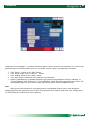
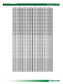
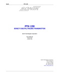
Instrument
Manual
Navigator+™
Programmer/Controller
®�
®�
8/2005 Rev A
®�
®�
Navigator+™™ Touch Screen
Programmer/Controller
Navigator +™
Touch Screen
Programmer/Controller
Standard Features
The Envirotronics Navigator+™ Programmer/Controller is
the newest instrument in the roster of touchscreen controllers
from Envirotronics. Expanded communication possibilities
include built-in RS232 and RS422/485 ports as well as
Ethernet and both USB host and device connection ports.
Remote management and “viewing” across an intranet or
internet connection, the ability to add PC peripherals such as
keyboard, mouse and printer, and high-speed connection for
PC file transfer combine with the ease of touchscreen and
intuitive command-screen design to make Navigator+™ a
leap forward in programmer/controller technology.
•
•
•
•
•
•
•
•
•
•
•
•
Touch Screen, TFT, 65,536 colors
640 x 480 display
400 MHz RISC CPU
32MB Intel Strata Flash, 64MB RAM
Windows CE.NET 4.2
RS232 (built-in) 9-pin D-SUB
RS485/422 (built-in) 25-pin D-SUB
Ethernet (built-in) 10/100Mbit RJ45/TP
USB Host for keyboard, mouse, printers, etc.
USB Device port for PC file transfer
Internal CF memory slot for memory
expansion 32 - 1024MB
External CF data slot for data capture and
extraction
1/2
Specifications
Channels:
3 Process Variables
Display:
65,536 Colors
TFT Display
Backlight
Display: 6.5” Diagonal
Resolution: 640 x 480 Pixels
Analog Outputs:
Standard 0 (none)
- up to 16 (optional)
Outputting your choice of information
Digital I/O:
Standard I/O; 0 (none)
- up to 128 in/128 out (optional)
Output 2A, 250 VAC
Voltage input 24 VDC
Operating System:
Microsoft Windows™ CE NET 4.2
Communications:
Ethernet 10/100 Mbit RJ45/TP
RS-232C 9-pin D-SUB
RS-485/422 25-pin D-SUB
Web server software
Storage:
1MB onboard, up to 1GB optional
- Test & data retrieval
Processors: 400 MHz RISC CPU
32MB Intel™ Strata Flash
64MB RAM
Peripherals: 1 USB Device for PC File Transfer
1 USB Host for Keyboard, Mouse,
Printer (through PC)
Programming:
-Limited to onboard storage
capacity
Software Features:
Full PLC diagnostics
Color graphic displays
TCP/IP networking
Real Time clock with battery
backup
Data Logging:
60 second intervals
data, setpoints, process variables, etc.
Alarms:
HLS-1, HLS-2, Circulator oil, HS oil
pressure, HS thermal head, HS Hi/Lo
pressure, LS oil pressure, LS thermal
head SW, LS Hi/Lo pressure, HS water
pressure, B oiler overtemp, Temp Sentry
(optional), Open sensor.
-Up to 16 alarms
Electrical/Mechanical:
Panel mount
Power requirements 24 VDC
(obtained through PLC on board)
Operating conditions:
During operation 0˚ to +55˚C
35% to 85% RH, non-condensing
During storage -20˚ to +70˚C
Input: 100-240 VAC 50-60Hz +10%-0%
Dimensions:
in. H 6.06 x W 8.62 x D 3.94
mm H 154 x W 219 x D 55
Weight: 2.5 lbs.
1.1 Kg
Analog Inputs:
Process voltage inputs 8 standard
assignable
- expandable to 40 (optional)
16 bit resolution
T/C 0.1˚C or 0.1˚F
Full temperature range
®�
2/2
8/05
®�
3881 N. Greenbrooke S.E.
Grand Rapids, MI 49512
Tel
(800) 368-4768 • (616) 554-5020
Fax
(800) 791-7237 • (616) 554-5021
Email [email protected]
[email protected]
Web www.envirotronics.com
Terms & Abbreviations
The following explains the different symbols and abbreviations used on the Navigator+™.
% Out
%
<
>
Alarms
Percentage of output for each channel.
Percent as in Process variable (i.e. % relative humidity)
Left arrow
Right Arrow
HLS-1
High Heat Limit
LS OPS
Low Stage Oil Pressure Switch
LS THS
Low Stage Thermal Head Switch
LS HLP
Low Stage Hi/Lo Pressure Switch
HS OPS
High Stage Oil Pressure Switch
HS THS
High Stage Thermal Head Switch
HS HLP
High Stage Hi/Lo Pressure Switch
HS WPS
High Stage Water Pressure Switch
TAS-1
Steam Generator Thermostat
CIRC O/L
Circulator Motor Overload Station 1
TEMP SEN
Temperature Sentry
SPARE 1 - 4
Spare Alarms - Use varies by application
Analog
Refers to type of input or output
CHx
A channel is a controlled value such a temperature, humidity, altitude, etc.
Example:
Channel 1 is Temperature Values
Channel 2 is Humidity Values
Circs
Circulator; Refers to the air circulation motor circuit.
Comps
Compressors
Comp.
Compensated type analog input device
Comp Ch
Compared channel for Compensated input.
Con outs
Control Outputs
Config
Configuration; Refers to the settings required to accomplish the desired task.
Control Ch#
See CHx above
D%
Derivative Percent
D time
Derivative Time
Dd
Date
DEL
Delete; Removal of a step or program
Dev.
Deviation; Difference between desired and actual
Dir
Direct acting; Refers to cooling outputs
Duration
Step length
Edit
Edit; Used to make changes in a profile.
Elapsed Time Time a profile has been running in a program step
ESC
Escape
Ev#
Event; Accompanied by a number, typically for customer use.
Evts
Events; Events are out relays that can be either manually operated or programmed into a profile.
File Save
Saves a new or edited profile
Gain
Proportional Gain % referred to as reset
GS
Guaranteed Soak Used to put a profile step’s programmed time into a hold mode. A value of “0” turns it off.
Sometimes referred to as a window or within a plus or minus value of desired temperature.
hhh
Hours; A profile steps time in hours
H Lim
High limit
High
The upper limit value.
Hold
Program is holding
Hys
Hysterisis
I Lag
I Lag; Integral delay setting in seconds.
Insert
Used in the program/edit profile screen
Loop
Brings you from the end of a current step to the beginning of a previous step, allowing the profile to cycle or nest.
Low
The lower limit value.
Log In
Security password required.
Log Out
Re-establishes security.
®�
®�
Terms & Abbreviations continued...
L Lim
Low limit
NC
Normally closed or No Connection dependant on where used.
Machine Section Reference to the location around the compressors.
Manual
From the main screen brings you to the manual operation screen of the controller. On the manual screen it turns the
chamber on to run to the assigned setpoints.
mm
Minutes A profile steps time in minutes.
mmm
Month
Next
Refers to following page.
Outputs
Are the PLC “y” relay outputs
Password
Security requirement.
P Bnd
Proportional Band; Window for control to begin adjusting its outputs to achieve the desired setpoint.
PID
Proportional, Integral, Derivative
PID Type
PWM, Analog, Open Loop, or Not used,
PID Settings
Values in controller that make the controller control.
PLC
Programmable Logic Control
Prev
Previous
Profile
A Profile is a series of steps programmed together to accomplish a test sequence.
Profile run
Brings you to the start page for timed start or instant start.
Pmp Down
Used to keep the high side of the refrigeration system run ready.
Pump down
See Pmp Down
Pump dwn sel Valve used to accomplish Pmp Down.
PV
Process Variable This is that actual value that the system is operating at for its corresponding channel
PWM
Pulse with modulation (Cycle Time)
Ramp
Changing a “SP” value in a profile to a new value. Found in the program editor.
Resume
Restarts a program profile.
Rev
Reverse acting; Refers to heating outputs.
Run
Runs the currently loaded program.
Soak
Dwell period at a given setpoint. Sometime referred to as a soak step. Staying at one set of values for an extended
period of time.
SP
Set Point; The value at which you wish to run the system for its corresponding channel
Start step
The first step you can set to start a profile. Allows to start a profile at other than its beginning.
Status
Displays the mode (Stop, Manual, Profile#)
STOP/RUN
Program run state; Also used in a program profile as an end step to shut the test off.
Stg1
Stage 1
Stp
Step; A Step is a single line of a test program.
Timed Start
Waiting to start at start time. (Program Setup)
Timed Stop
Program stopped at selected stop time. (Program Setup)
Trend
Graphical display of the current process variables.
VAL
Value
X#
PLC input value accompanied with a number.
Y#
A “Y” with a number represents an output relay from the PLC
Yy
Year
®�
®�
Figure 1.0 • Program Page
1.19
1.1
1.18
1.17
1.16
1.2
1.15
1.3
1.4
1.14
1.5
1.13
1.6
1.1
1.2
1.3
1.4
1.5
1.6
1.7
1.8
1.9
1.10
1.11
1.12
1.13
1.14
1.15
1.16
1.17
1.18
1.19
1.7
1.8
1.9
1.10
1.11
1.12
Current Setpoint and process values for the channels of control.
The first value on the left is the “Set Point” This is the desired value that you enter manually or are running from
the program you created The next number is referred to as the “process variable” This is the actual value
that is running for its corresponding channel.
Displays current step running in the selected profile. Can also be used to view another step by touching the block
after the Step# and entering in another step number. When the program advances to another step it will reset to
the current step running.
Type of step the current step is.
Event status for the current step
A 5 step view of the current profile in memory.
Prev – Brings you to the Trend/Setup screen.
Help – Brings you to a “Help” screen.
Run – Direct jump to the ‘Profile/Login’ screen.
Pause – Puts the current program on hold.
Resume – Resumes program in progress.
Stop – Puts the Navigator+™ controller in ‘Stop’ mode.
Next – Brings you to the Profile/Login screen (same as 1.8).
Scrollbar used to scroll up and down the profile currently in memory.
Indicator of time elapsed for the current step.
Duration control for the current step.
Displays current events that are on.
Current status of the controller (i.e. Profile, Manual, Trip, or Stop).
Current running step.
Current date and time.
®�
®�
Figure 1.8 • Profile Run
1.8.9
1.8.1
1.8.8
1.8.2
1.8.7
1.8.3
1.8.1
1.8.2
1.8.3
1.8.4
1.8.5
1.8.6
1.8.7
1.8.8
1.8.9
1.8.4
1.8.5
1.8.6
Start Step - Reset all elapse timers and loop iteration counters then begins execution of the profile. Step to start
execution of the profile currently in memory.
Start – Start the selected program to run.
Prev- Returns to program profile screen
Pause – Puts the current program on hold.
Resume - Resumes a previously paused profile.
Stop - Puts the Navigator+™ controller in ‘Stop’ mode.
Time of day start – Displayed in military time.
Month Day Year – Display for date of delayed start.
Check mark – Activates delay start feature if checked.
Start, via Program
Lets you start a selected preprogrammed profile.
See: Programming a Profile if no programs are available.
Note that you must have a program selected to run.
After selection is entered, the system will start the selected program.
There are two ways to get to the profile run screen. You can scroll to the profile screen using the (Prev/Next) buttons.
Look for the login, logout, profile screen and press the “Run Profile” button Figure 5 detail (5.4). or you can go from
Figure 1 detail (1.8) and press the “Run” button. (You must be logged in)
Program Starting Step lets you assign a starting step number, other than step 1, to start at in the program. (Figure 1.8
detail 1.8.1) After the above has been completed press the “start” button. (Figure 1.8 detail 1.8.4). The program will load
and begin to run. The Status will say “Profile” (Figure 1 detail 1.14). To Stop the program press any “Stop” button that
you see.
Start Time Enabled allows you to enter a date and time at which you would like the program to actually begin
controlling, if not immediately. This option will start both the system and the program. You must press the check mark
button on the Navigator+™ for the option to work correctly. (Figure 1.8). (A level 4 password is required to start a
program). Start Step (1.8.1). Delayed Start enabled (1.8.8) checked. Date and time (1.8.6)
®�
®�
Figure 2.0 • Manual Page
2.10
2.9
2.8
2.7.5
2.1
2.7
2.6
2.2
2.1
2.2
2.3
2.4
2.5
2.6
2.7
2.8
2.9
2.10
2.3
2.4
2.5
Current Setpoint and process values for the channels of control. Touching on the setpoint value will allow you to
enter a new value. Press the key in the lower right corner of numberical keypad will enter value.
Prev - Brings you to the Profile/Login screen.
Manual – Starts the controller in manual mode.
Stop - Puts the Navigator+™ controller and system in ‘Stop’ mode.
Next - Brings you to the Trend/Setup screen.
Events- Touching the event buttons will turn them on/off. When the number is displayed the event is on.
Current status of the controller (i.e. Profile, Manual, Trip, or Stop).
Alarms – Direct jump to the alarm list screen.
Alarm Silence- Silences the alarm trip sonalert
Manual Mode-Displays mode of operation page name.
MANUAL CONTROL
General information
Starting the Navigator+™
The Navigator+™ controller has 2 ways to start control. One method of starting control is by using manual control.
The other method is by utilizing the Program Setup Mode and a program.
Starting the System Manually
Press the “Prev/Next” to scroll to the “Manual Run” screen. Figure (2). To enter a setpoint value, touch the
corresponding button after the Ch# and below the SP Figure 2 detail (2.1). A number pad will appear. Enter the desired
numerical value for the corresponding channel then hit the key in the lower right corner of the numerical pad.
Note. You may have up to 3 channels of control based on your application, enter as required for your system.
Next turn on or off the events that are desired. This is done by pressing the keys as per figure 2 detail (2.6) If a number is
present the event is on.
continued…
®�
®�
Figure 2.0 • Manual Page continued...
Channel 1 S.P. sets the setpoint of channel 1.
Channel 2 S.P. sets the setpoint of channel 2. (Optional)
Channel 3 S.P. sets the setpoint of channel 3. (Optional)
Start Manual Mode
After the desired values have been entered press the “Manual” button at the bottom of the page. Figure 2 detail (2.3)
The status area on the display will say “Manual” and the chamber will begin to operate provided all safeties are satisfied.
Figure 2 detail (2.7). To Stop the manual operation press the stop key at the bottom of the page. Figure 2 detail (2.4).
The status area on the display will say “Stop” and the chamber will shut off. Figure 2 detail (2.7). (Pump down will
remain active if equipped).
®�
®�
Figure 4.0 • Jump To
4.8
4.1
4.7
4.2
4.6
4.3
4.4
4.1
Trend - Direct jump to the graphic chart screen. See Fig 4.1
4.2
All Watch – Direct jump to the ‘All Watch’ screen. Allows user to watch the (x inputs and y ouputs of the PLC as
system is running). See 4.2
4.3
Prev - Brings you to the Program screen.
4.4
Stop – Stops System
4.5
Not applicable
4.6
System - Can view additional plc data. i.e. plc register values, memory bit status’s for high or low. See Fig 4.6
4.7
Setup - Direct jump to the setup ‘Setup Menu’ screen. Location of PID, Alarm configuration, analog
assignments, etc. See Fig 4.7
4.8
Alarms - Brings you to the alarms screen. See Fig 4.8
®�
®�
Figure 4.1 • Graphic Chart Screen
4.1.1
4.1.2
4.1.3
Set low range of graph.
Set high range of graph.
Function Bar. Touch
area to see
4.1.3
4.1.1
4.1.2
Figure 4.2 • All Watch
4.2 All Watch - Direct jump
to the ‘All Watch’ screen
Allows user to watch the
(x inputs and y ouputs of
the PLC as system is
running).
4.2.1 Displays current P.V.
and percentage of
Output
4.2.2 Displays PLC (input)
(y output) as on or off.
Star is on.
4.2.3 Prev – Returns to
Jump To screen.
4.2.1
4.2.4
4.2.2
4.2.3
Stop – Stops System
4.2.4
®�
®�
Figure 4.6 • System
4.6.1
4.6.2
4.6.3
4.6.4
4.6.5
4.6.6
4.6.7
Scroll down arrow
Delete key
Overrides a value
Select a new bit
Zoom in scroll
Up Arrow
ESC; Returns to previous page
NEW
Will let you examine the contents of the PLC registers. You can choose the type of register by selecting one of the
following followed by the number of the particular register you wish to view. This will create a list on the display as you
select more and more registers. Touch NEW and enter the register you wish to view - such as D40
(1) M
(2) T
(3) C
(4) D
(5) X
(6) Y
(7) S
Memory Registers
Timer Registers
Counter Registers
Data Registers
PLC Input Status
PLC Output Status
PLC State Registers
®�
®�
Figure 4.7 • Set Up
4.7.1
4.7.9
4.7.2
4.7.8
4.7.3
4.7.7
4.7.4
4.7 Setup –
4.7.1
4.7.2
4.7.3
4.7.4
4.7.5
4.7.6
4.7.7
4.7.8
4.7.9
4.7.5
4.7.6
Direct jump to the setup ‘Setup Menu’ screen. Location of PID, Alarm configuration, analog
assignments, etc.
Log In - Logs you into the controller to make changes based on password level.
Log Out - Logs you out of control change screens. The system will automatically log you out after
30 minutes
Passwords - Allows for changing passwords up to level 6.
Analog setup - Allows for the setup values of channel inputs.
Alarms setup - Allows for the setup for the system alarms.
Control outputs - Allows for the output relays of machine operation.
PLC Reset - Used to reset the PLC for changes made in setup.
Factory - Factory Settings
PID - Allows for the channel proportional, intregal, and derivitive values to be changed.
®�
®�
4.7.3 Passwords
Level 1
Level 2
Level 3
Level 4
Level 5
Level 6
Level 7
Level 8
Allows access for System Profile Run
Allows access for Program Editing
Allows access for PID Adjustments
Allows access to Factory Settings
®�
®�
Figure 4.7.4 • Analog Set Up
4.7.4.13
4.7.4.1
4.7.4.12
4.7.4.2
4.7.4.11
4.7.4.3
4.7.4.10
4.7.4.4
4.7.4.9
4.7.4.5
4.7.4.6
4.7.4.7 4.7.4.8
4.7.4 Analog setup - Allows for the setup values of channel inputs.
4.7.4.1
4.7.4.2
4.7.4.3
4.7.4.4
4.7.4.5
4.7.4.6
4.7.4.7
4.7.4.8
4.7.4.9
4.7.4.10
4.7.4.11
4.7.4.12
4.7.4.13
Low; Engineering unit low setting.
High; Engineering unit high setting.
Type; Input type.
Offset; Offset setting.
Sample; Number of samples used in a rolling average.
Prev; Returns you to the set up menu.
Back Arrow; Go to the previous analog channel for setup.
Forward Arrow; Advance to the next analog channel for setup.
Current reading; Current reading of the analog channel in the calculated engineering units.
Current Analog; Current actual analog reading.
Comp Ch; Analog channel used in compensation calculation.
Comp; Type of compensation to execute.
Label of the current channel being setup.
®�
®�
Figure 4.7.5 • Alarms
4.7.5.1
4.7.5.2
4.7.5.3
4.7.5.4
4.7.5.5
4.7.5.6
4.7.5.7
4.7.5.8
4.7.5.9
4.7.5.10
4.7.5.11
4.7.5.12
4.7.5.13
4.7.5.14
4.7.5.15
4.7.5.16
4.7.5.17
4.7.5.18
Type of alarm signal (i.e. digital or analog) .
Input selection for digital alarms.
Channel selection for analog alarms.
Common state of digital type alarms.
Specifies if controller should halt if alarm occurs.
Return to the Set Up menu.
Low limit for analog type alarms.
Stop System.
High limit for analog type alarms.
Go to the previous alarm for setup.
Advance to the next alarm for setup.
Hystersis setting for analog type alarms. Operating window to prevent a short cycling of the switch.
Sometimes referred to as a make and break value.
Example: Open at 10PSI Close at 20 PSI
Duration of time alarm must be active before registering. True is auto / False is manual.
If secondary analog sensor is on another channel - wait until both show trip.
Alarm automatic reset.
Brings you to the alarm page.
Silences the audible alarm bell.
This is the name of the alarm.
Accessible at Password Level 4
®�
®�
Figure 4.7.6 • Control Outputs
4.7.6.1
4.7.6.2
4.7.6.3
4.7.6.4
4.7.6.5
4.7.6.6
4.7.6.1
4.7.6.6
4.7.6.2
4.7.6.5
4.7.6.3
4.7.6.4
Stage one output of direct acting PID output. (Cooling)
Time delay before applying second stage of reverse acting PID output. (Cooling)
Stage two output of direct acting PID output. (Cooling)
Stage two output of reverse acting PID output. (Heating)
Time delay before applying second stage of reverse acting PID output. (Heating)
Stage one output of reverse acting PID output. (Heating)
4.7.7 PLC Reset
Resets value changes made to the PLC. This must be done any time analog or digital items are changed on the Set Up
pages
®�
®�
Figure 4.7.9 • PID
4.7.9.18
4.7.9.17
4.7.9.16
4.7.9.19
4.7.9.1
4.7.9.15
4.7.9.2
4.7.9.3
4.7.9.4
4.7.9.5
4.7.9.6
4.7.9.7
4.7.9.11
4.7.9.8
4.7.9.9
4.7.9.9
4.7.9.11
4.7.9.12
4.7.9.13
4.7.9.10
4.7.9.14
4.7.9 PID - Allows for the channel proportional, integral, and derivative values
4.7.9.1
Control Channel
4.7.9.2
PBand Proportional Band
4.7.9.3
Gain Proportional Gain % referred to as reset
4.7.9.4
I Lag Integral delay setting in seconds.
4.7.9.5
I
Integral time in seconds.
4.7.9.6
Derivative time in seconds
4.7.9.7
D % Derivative %
4.7.9.8
Prev Returns to Set Up Menu
4.7.9.9
REV Represents the entire column for heating values (Reverse acting)
4.7.9.10
SP
Setpoint for respective channel at top of screen.
4.7.9.11
DIR Represents the entire column for cooling values. (Direct acting).
4.7.9.12
PV
Process Value (Actual channel value)
4.7.9.13
%out % of output for reverse or direct acting mode.
4.7.9.14
Window Deviation above or below SP.
4.7.9.15
> Middle limit for PID set selection. Value indicated at left is the value and above that
the proportional band window is operating at.
4.7.9.16
p2-2 Jump to next PID screen.
4.7.9.17
Between these two values the respective proportional band is in effect.
4.7.9.18
PID settings for below this level (column 1). Column 2 is for between settings in above
to this setting. Etc. for page 2 of 2.
4.7.9.19
High limit for PID set selection.
Password security level 4 or higher is required to access
®�
®�
Figure 4.8 • Alarms
4.8 Alarms
Brings you to the alarms screen.
4.8.1
4.8.2
4.8.3
4.8.4
4.8.5
4.8.6
4.8.7
4.8.8
Down arrow; Scrolls page down.
Shows alarm information
Reset; Resets the alarm
Zoom; Enlarges view.
Check; Acknowledges alarm
Up arrow; Scrolls page up
ESC; Escape, returns to previous page
Alarm; Displays alarm history and any active alarms.
®�
®�
Figure 5.0 • Log In
5.1
5.7
5.2
5.6
5.3
5.1
5.2
5.3
5.4
5.5
5.6
5.7
5.4
5.5
Login - To enter your password at one of six levels.
Profiles – Select from one of five program profiles. (Must be logged in to password level 2 or higher)
Prev - Returns to the main screen.
Run Profile - Brings you to the run program screen. Start time, date etc.
Next - Forwards you to the manual screen.
Edit Profile - Allows for the editing of an currently loaded program profile.
Log out - Removes access to the everything but the stop feature and Manual mode.
®�
®�
Figure 5.2 • File
5.2.1
5.2.5
5.2.2
5.2 Profiles –
5.2.1
5.2.2
5.2.3
5.2.4
5.2.5
5.2.3
5.2.4
Select from one of five program profiles.
Profile; Program profile, check desired profile, and “Open” or “Save”
Prev; Previous page.
Open; Opens the selected file.
Saves; Saves an edited file.
File name; Profile name.
®�
®�
Figure 5.2.1 • File Open
5.2.1.1
5.2.1.2
5.2.1 Profile Program profile, check desired profile, and “Open”
Verifies your desire to open program.
5.2.1.1 Prev Returns to previous page.
5.2.1.2 Open Opens the desired program profile.
®�
®�
Figure 5.2.4 • File Save
5.2.4.1
5.2.4.2
Prev
OK to save file
®�
®�
Figure 5.6.1 • Edit Profile
5.6.12
5.6.14
5.6.13
5.6.11
5.6.1
5.6.10
5.6.2
5.6.3
5.6.9
5.6.4
5.6.8
5.6.5
5.6.6
5.6.7
5.6 Edit Profile- Allows for the editing of an existing program profile.
5.6.1 Step# Displays step being edited. Touch to change.
5.6.2 Type
Displays type of step (Soak,Ramp,Loop, Stop)
5.6.3 Events When number is displayed it is “On”
5.6.4 Program display Shows a 5 step window of program
5.6.5 Prev
Returns to Log In menu
5.6.6 Delete Deletes the step shown.
5.6.7 Insert Inserts a step before step shown.
5.6.8 Down arrow Walks through program
5.6.9 Up Arrow Walks through program
5.6.10 Duration Step time interval
5.6.11 GS/Loop Guaranteed soak window on loop to step numbver
5.6.12 CH1
Enter desired set point for current step
5.6.13 0 = Blank; 1 = GS Win; 3 = Blank; 4 = Loop to
5.6.14 0 = Stop; 1 = Soak at; 2 = Ramp to; 3 = Loop to
®�
®�
Editing a Program
Using the Prev/Next key scroll to the Profiles Page (Figure 5.1)
(Login to a security level of at least two (2) to edit a program.)
(Figure 5.1 Detail 5.1)
Press the Profiles button (Figure 5.1 detail 5.2) and the file screen will open. Select the file
you wish to edit by touching the box in front of the desired file. (Figure 5.2 detail 5.2.1) then
press open
Then press the Edit Profile button. (Figure 5.1 detail 5.6)
The edit profile screen will now be displayed. (Figure 5.6)
First is to select the step number of your program. (detail 5.6.1) Pressing the button will
provide a numerical display. Enter the desired step number (if change is needed) and press
the enter key.
Step Type:
Then (if required) select the type of step (detail 5.6.2), soak, ramp, loop or stop.
Programming Events
Each programming step lets you activate any or all of the up to 8 event outputs.
Event Outputs On lets you activate the event outputs 1 through 8 for this step. Enter the output
numbers, in any order, of the events you wish to turn on. Any of the 8 events that were not selected will
be set to OFF once you hit ENTER and selected ones set to ON.
Determine the events that may be required to perform the step function. To turning an event
on touch the button and the number of the event should appear.
Now select the Ch1 temperature (detail 5.6.13) by touching the button. A numerical display will
appear. Type in the desired value for your applications step and press the enter key.
Guaranteed Soak
If guaranteed soak (GS) is required press the button identified as (detail 5.6.12) and enter a
value via keypad. This value is the numerical amount of deviation allowed before the program
can advance.
Guaranteed Soak affects the way a step behaves in terms of its time duration. If G-Soak is
ON, (a value entered) the controller will wait until it achieves a process variable within the
window and then will begin the countdown for that step TIME DURATION. If G-Soak is OFF,
the controller will try to achieve the set point for that step within the TIME DURATION for that
step, thus, the controller begins its countdown as soon as the step is begun.
Ch. 1 GS
Ch. 2 GS
Ch. 3 GS
A Value of “0” is the off function for guaranteed soak
®�
®�
Editing a Program continued...
Soak Window Adjustment
With Guaranteed Soak on, the TIME DURATION counter does not begin until you have
reached your setpoint window. If your Process Variable (P.V.) has any variance outside of the
window, your counter will cease until it reaches the setpoint window again.
G-Soak for channel 1 is on, setpoint is at 140 degrees F, but the P.V. varies by 2
or 3 degrees off the setpoint. If the WINDOW for the channel is +/- 5, the steps counter will
continue. If the P.V. varies more than 5 degrees off setpoint, the step counter will stop until it is
back with-in the specified window.
Example:
Note:
Using G-Soak in a “ramp” step will cause the controller to stop the program clock and not
allow the program to progress. As a result, the program will never advance to the next step.
Use G-Soak only in “soak” steps.
Step Time Duration (detail 5.6.11) tells the controller the amount of time this step is to take to
achieve the given setpoint (w/ G-Soak OFF), or the amount of time that the step remains at the
given setpoint (w/ G-Soak ON). It is in Hours:Minutes:Seconds. The maximum amount of time
that can be entered on any one step is 99 hours 59 minutes and 59 seconds.
Selecting a Program to Run
To choose a program to run you must scroll to the profiles screen. Figure 5
“Profiles” button (detail 5.2”).
Press the
Select a Program Name or Number
You are now on the File screen. Select from one of the five (5) available programs. Figure 5.2
detail 5.2. by placing a checkmark in front of the desired profile. Then press the open button. It will
ask you to then acknowledge this selection. Press the open key Figure 5.2.1.1.
Now press the “run” key and follow the Start via Program steps.
®�
®�
Remote Command Set
Here we will show you the commands available to you via the remote COMMAND mode. This section is
divided into 7 sections listed below.
Program & System Control
Manual Control
Alarm Control
In this section, the following conventions are observed:
monospace bold words
are sent to the controller exactly as shown
italicized
represent a variable value to be sent
channel
represents a valid channel number
alarm
represented by ALM and a corresponding number.
All commands are case sensitive and must be in capitol letters.
NOTE: Serial setup to communicate with the Navigator+™ via RS-232 must be:
Baud Rate
Parity
Databits
Stopbits
9600
Even
7
1
System Control
These commands control the starting and stopping of the system. They correspond to the options
available when the MANUAL and STOP keys on the front panel are pushed.
STP
has the same effect as pressing the STOP button.
STR
starts the system.
Manual Control
EVevent_num 0/1
sets the specified event to the specified state.
Example: EV1 1 for “ON” and EV2 0 for “OFF”
EVevent_numR
returns the current state of the specified event as
either 1 for “ON” or 0 for “OFF”.
SPchannel
channel value
sets the setpoint for a specified channel. Example:
SP1 235 would be 23.5.
SPchannelR
returns the specified channel’s setpoint.
PVchannel
returns the specified channel’s P.V.
®�
®�
Remote Command Set continued...
Alarm Control
These commands control and get data about the system alarms
ALMalarm
alarm number
returns the current state of the specified alarm.
Either “0” or “1” is returned. 0 shows alarm is
“OFF” and 1 shows the alarm is activated.
Alarms:
Note: Some alarms listed below may not be used on your system. Verify with the electrical print for the
alarms for your chamber.
ALM1
ALM2
ALM3
ALM4
ALM5
ALM6
ALM7
ALM8
ALM9
ALM10
ALM11
ALM12
ALM13
ALM14
ALM15
ALM16
Chamber High Heat Limit alarm one (HLS-1)
Chamber High Heat Limit alarm two (HLS-2)
Circulator Motor Overload (C/OL)
HS Oil Pressure Switch (HOPS)
HS Thermal Head Switch (HTHS)
HS Hi/Lo Pressure Switch (HHLP)
LS Oil Pressure Switch (LOPS)
LS Thermal Head Switch (LTHS)
LS Hi/Lo Pressure Switch (LHLP)
HS Water Pressure Switch (WPS)
Boiler Over Temp (TAS-1)
Temp Sentry
Spare Alarm one
Spare Alarm two
Spare Alarm three
Open Thermocouple
Example Commands:
SP1 250
ALM1
PV1
EV1R
SP1R
STR
STP
EV1 1
This command will set the channel 1 setpoint to 25.0.
This command will read back the alarm status of Alarm 1.
This command will read back the current temperature of channel 1. Please note that this
command must contain a space after the one and before the carriage return.
This command will read back the current status of Event 1. 1 signifies ON and 0
signifies OFF.
This will read back the current setting of Setpoint 1.
This command will start the controller in manual mode
This command will stop the controller
This command will turn on Event 1.
®�
®�
Calibration
Navigator+™ Calibration
Calibration of the Navigator+™ chamber controller requires “Setup” access to the instrument. If a “Setup” level
password was not provided contact your RTP for details. Once a “Setup” level password is entered…
1.
2.
3.
4.
5.
Click “More>>” button on the “Main Screen”
Click “Setup” button on the “Jump to…” screen
Click “Analog” button on the “Setup” screen
Click “Next” button to advance to the channel to be calibrated.
Attach a calibrated NIST traceable standard to the channel being calibrated. Record “Standard” vs.
“Current Reading” data. Determine if “Current Reading” values are within permissible error limits. If an
unacceptable degree of error is discovered, adjust the offset to obtain acceptable results.
Note:
Many factors can contribute to inconsistent and/or unacceptable levels of error. Good wiring and
shielding practices are required for best results. Thermocouple input channel “High” and “Low” settings have
no effect, however an offset value can be entered.
®�
®�
˚C to ˚F Conversion
C
-80
-79
-78
-77
-76
-75
-74
-73
-72
-71
-70
-69
-68
-67
-66
-65
-64
-63
-62
-61
-60
-59
-58
-57
-56
-55
-54
-53
-52
-51
-50
-49
-48
-47
-46
-45
-44
-43
-42
-41
-40
-39
-38
-37
-36
F
-112.00
-110.20
-108.40
-106.60
-104.80
-103.00
-101.20
-99.40
-97.60
-95.80
-94.00
-92.20
-90.40
-88.60
-86.80
-85.00
-83.20
-81.40
-79.60
-77.80
-76.00
-74.20
-72.40
-70.60
-68.80
-67.00
-65.20
-63.40
-61.60
-59.80
-58.00
-56.20
-54.40
-52.60
-50.80
-49.00
-47.20
-45.40
-43.60
-41.80
-40.00
-38.20
-36.40
-34.60
-32.80
C
-35
-34
-33
-32
-31
-30
-29
-28
-27
-26
-25
-24
-23
-22
-21
-20
-19
-18
-17
-16
-15
-14
-13
-12
-11
-10
-9
-8
-7
-6
-5
-4
-3
-2
-1
0
1
2
3
4
5
6
7
8
9
F
-31.00
-29.20
-27.40
-25.60
-23.80
-22.00
-20.20
-18.40
-16.60
-14.80
-13.00
-11.20
-9.40
-7.60
-5.80
-4.00
-2.20
-0.40
1.40
3.20
5.00
6.80
8.60
10.40
12.20
14.00
15.80
17.60
19.40
21.20
23.00
24.80
26.60
28.40
30.20
32.00
33.80
35.60
37.40
39.20
41.00
42.80
44.60
46.40
48.20
C
10
11
12
13
14
15
16
17
18
19
20
21
22
23
24
25
26
27
28
29
30
31
32
33
34
35
36
37
38
39
40
41
42
43
44
45
46
47
48
49
50
51
52
53
54
F
50.00
51.80
53.60
55.40
57.20
59.00
60.80
62.60
64.40
66.20
68.00
69.80
71.60
73.40
75.20
77.00
78.80
80.60
82.40
84.20
86.00
87.80
89.60
91.40
93.20
95.00
96.80
98.60
100.40
102.20
104.00
105.80
107.60
109.40
111.20
113.00
114.80
116.60
118.40
120.20
122.00
123.80
125.60
127.40
129.20
C
F
55
56
57
58
59
60
61
62
63
64
65
66
67
68
69
70
71
72
73
74
75
76
77
78
79
80
81
82
83
84
85
86
87
88
89
90
91
92
93
94
95
96
97
98
99
131.00
132.80
134.60
136.40
138.20
140.00
141.80
143.60
145.40
147.20
149.00
150.80
152.60
154.40
156.20
158.00
159.80
161.60
163.40
165.20
167.00
168.80
170.60
172.40
174.20
176.00
177.80
179.60
181.40
183.20
185.00
186.80
188.60
190.40
192.20
194.00
195.80
197.60
199.40
201.20
203.00
204.80
206.60
208.40
210.20
®�
®�
°C to °F (continued)
C
F
C
F
100
101
102
103
104
105
106
107
108
109
110
111
112
113
114
115
116
117
118
119
120
121
122
123
124
125
126
127
128
129
130
131
132
133
134
135
136
137
138
139
140
141
142
143
144
212.00
213.80
215.60
217.40
219.20
221.00
222.80
224.60
226.40
228.20
230.00
231.80
233.60
235.40
237.20
239.00
240.80
242.60
244.40
246.20
248.00
249.80
251.60
253.40
255.20
257.00
258.80
260.60
262.40
264.20
266.00
267.80
269.60
271.40
273.20
275.00
276.80
278.60
280.40
282.20
284.00
285.80
287.60
289.40
291.20
145
146
147
148
149
150
151
152
153
154
155
156
157
158
159
160
161
162
163
164
165
166
167
168
169
170
171
172
173
174
175
176
177
178
179
180
181
182
183
184
185
186
187
188
189
293.00
294.80
296.60
298.40
300.20
302.00
303.80
305.60
307.40
309.20
311.00
312.80
314.60
316.40
318.20
320.00
321.80
323.60
325.40
327.20
329.00
330.80
332.60
334.40
336.20
338.00
339.80
341.60
343.40
345.20
347.00
348.80
350.60
352.40
354.20
356.00
357.80
359.60
361.40
363.20
365.00
366.80
368.60
370.40
372.20
C
190
191
192
193
194
195
196
197
198
199
200
201
202
203
204
205
206
207
208
209
210
211
212
213
214
215
216
217
218
219
220
221
222
223
224
225
226
227
228
229
230
231
232
233
234
F
C
F
374.00
375.80
377.60
379.40
381.20
383.00
384.80
386.60
388.40
390.20
392.00
393.80
395.60
397.40
399.20
401.00
402.80
404.60
406.40
408.20
410.00
411.80
413.60
415.40
417.20
419.00
420.80
422.60
424.40
426.20
428.00
429.80
431.60
433.40
435.20
437.00
438.80
440.60
442.40
444.20
446.00
447.80
449.60
451.40
453.20
235
236
237
238
239
240
241
242
243
244
245
246
247
248
249
250
251
252
253
254
255
256
257
258
259
260
261
262
263
264
265
266
267
268
269
270
271
272
273
274
275
276
277
278
279
455.00
456.80
458.60
460.40
462.20
464.00
465.80
467.60
469.40
471.20
473.00
474.80
476.60
478.40
480.20
482.00
483.80
485.60
487.40
489.20
491.00
492.80
494.60
496.40
498.20
500.00
501.80
503.60
505.40
507.20
509.00
510.80
512.60
514.40
516.20
518.00
519.80
521.60
523.40
525.20
527.00
528.80
530.60
532.40
534.20
®�
®�
Technical Specifications
Sensor Descriptions
Range Accuracy (typical @ 25°C and 5 VDC)
Description
Typical Accuracy
± 15 mV
± 50 mV
± 100 mV
± 500 mV
±1V
± 5V
± 20 mA
J Thermocouple 0 to 760 ˚C
T Thermocouple -100 to 400˚C
± 0.03 mV
± 0.015 mV
± 0.0055 mV
± 0.005 mV
± 0.005 V
± 0.005 V
± 0.008 mA
± .4˚C
± .5˚C
Available Selections
0 - 10 VDC
± 10 VDC
4 - 20 mA
J Thermocouple ˚C
T -Thermocouple ˚C
T -Thermocouple ˚F
®�
®�