1
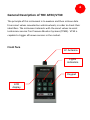
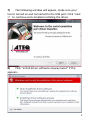
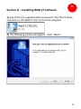
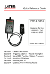
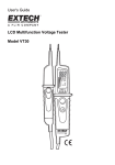
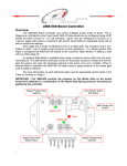
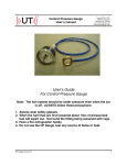
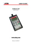
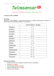
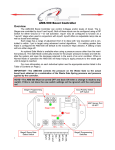
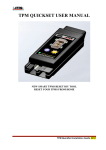
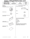
Quick Reference Guide VT30 Customer Service 1-888-621-TPMS 1-888-621-8767 Section A – General Description Version: MJC-1108Section B – Triggering a Sensor / Results Description US1 Section C – Installing USB Drivers Section D – Installing WEB VT Section E – Updating VT30 / Printing Results A General Description of THE ATEQ VT30 The principle of this instrument is to awaken and then retrieve data from smart valves mounted on vehicle wheels, in order to check their identifiers. The instrument interacts with the smart valves to assist technicians service Tire Pressure Monitor Systems (TPMS). VT30 is capable to trigger all known sensors in the market. Front face LF Antenna Lights indicators Keypad LCD display Connectors 9V DC USB Port (Web VT) Battery Connection Power Supply connector VT30 operates with 9V battery USB connector The USB connection allows software updates to be installed onto the tool using the WEB VT program. TPM sensor results can also be printed using this program. 3 SECTION B - TRIGGERING SENSOR(S) B B.1 TESTING A TPM SENSOR Step 1 – Select the "VEHICLE SELECTION" menu and confirm selection with the key. Step 2 – Select the vehicle brand on the screen by using the or keys and confirm selection with the M A INM E N U >V E H IC L ES E L E C T IO N R K ET E S T S E T T IN G S S E L E C T IO N C A D IL L A C C H E V R O L E T C H R Y S L E R key. Step 3 - Hold the tool within a few inches from the TPM sensor. Some sensors may require the tool position directly on the rubber tire, over the valve stem. Some sensors are banded to the wheel and can be located 180⁰ opposite the valve stem. (Refer to owner’s manual) 4 Step 4 - Press the key. The tool will begin to send LF trigger and the TX light will flash. Depending on the sensor, the tool will activate the sensor on the first or last step. Each step identifies the number of valve types used on the vehicle brand. Step 5 – The tool will vibrate/beep after receiving the sensor information. The tool will display the sensor ID, pressure, and sensor state of the valve that is triggered. If the tool does not receive the correct information, the fail LED will illuminate and you can restart the trigger sequence by pressing the -----------------C H R Y S L E R --------------. L E F TF R O N T ------------ ( ) (C) (TEST) SELECTTIRE RETURNTOM ANU READSENSOR -----------------C H R Y S L E R --------------. L E F TF R O N T ------------ S T E P :1o f3 [C ]:S T O P T R IG G E RP R O C E S S IN G L ow B at P ass 84031C3F Fai l V EH IC LE LEFTFR O N T 78°F BAT:OK (C)MENU (T)START L ow B a t Tx 32.24PSI 1.0g 315MHz () NEXT Pass Fa i l Tx key again. 5 Step 6- Follow the same procedure for the rest of the three or four wheels by pressing the key and then key. (Refer to vehicle owners manual or other reference guides for TPM reset procedure.) B.2 RESULTS DESCRIPTION The picture below is an example of a valve data communication result: Vehicle brand Valve identifier Internal wheel Temp. Valve battery status 84031C3F 78°F BAT:OK (C) MENU (T) START CH RY SLER LEFT FRONT Tire internal pressure 32.24 PSI 1.0 g 315MHz ( ) NEXT When blinking Instrument is ready to test again **Note: The VT30 will identify the sensor information that is transmitted. Not all sensors transmit every piece of information shown. *** 6 Section C – Installing USB Drivers D C 1) Please insert the CD that was provided with the VT30. 2) Connect the USB wire to the USB connector of your PC and VT30. Then turn on the instrument. 3) The following window will appear. Click the “Cancel” button in the bottom right corner of the screen. 4) In the CD drive, open the file “ATEQ USB Driver for VT30”. 5) The following screen will appear. Depending on your operating system, open the file for “XP” or “VISTA”. 7 6) Using “VISTA” file as an example, the following window may appear. Select “Allow”. 8 7) The following window will appear, make sure your tool is turned on and connected to the USB port. Click “next >” to continue and complete installing the driver. 8) Click “Install driver software anyway twice” if this appears. 9 9) When the drivers are successfully installed, the following window will appear. Click “Finish”. **Note: Please refer to the user manual on CD for detailed instruction when using Windows XP. There are additional instructions if you are trying to use the RJ45 port with RS232 connection. 10 Section D – Installing WEB VT Software D 1) Insert the CD, supplied with instrument, into the PC drive and click on the WebVT icon to start the program. 2) The following screen will appear. Click “Next>” 11 3) The following window will appear, please select the location you would like to save the program. Click “Next>”. 4) Click “Yes” when this window appears. 5) Click “Finish” when the WebVT installation is complete. 12 Section E – Updating VT30 / Printing Results E 1) Connect the USB cable from the VT30 to the PC. Click on the WEB VT Icon to start the program. 2) The following screen appears. You may “Update Device” or print “Valve ID’s” from here as well. 13 3) Press “Yes” to update to the latest software version. Update will take several minutes to complete and the status bar will indicate the percentage of update completed. 4) When the update is complete, disconnect the VT55 USB cable and close the program. **Note: You must have an internet connection to update the VT30 with WEB VT software. 14 ATEQ Corporation 35980 Industrial Livonia, MI 48150 www.tpms-tool.com 15