1
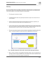
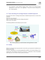
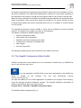
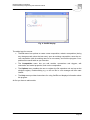
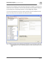
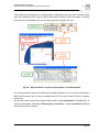
Federal Waterways Engineering and Research Institute
BUNDESANSTALT FÜR WASSERBAU
Karlsruhe • Hamburg • Ilmenau
OpenMI compliant Import
of Initial and Boundary Data
into Delft3D
User Manual, v. 1.0
2007-08-29
Bundesanstalt für Wasserbau
OpenMI compliant Import of Initial and Boundary Data into Delft3D
Summary
Are you a modeller and are you asking yourself how to import data into a numerical engine?
Converting the data into the appropriate format before runtime would be the traditional way.
This manual explains a more generic approach using OpenMI:
•
The data gets converted at runtime
•
It is directly imported from the proprietary files without output in the format of the numerical engine.
•
Generic approach means that the numerical engine can easily be replaced by another one and that the data reader can be replaced as well.
•
In the concrete case the numerical engine is Delft3D-Flow and its initial and boundary
data can be read from proprietary BAW file formats. Already existing files which have
been generated for import into other numerical engines can be re-used.
•
The user can steer the import and the simulation itself with the OpenMI configuration
editor. Connections between components can be established by mouse click.
Fig. 1: OpenMI configuration editor with a network where data gets imported.
•
Fig. 1. shows a network in the OpenMI configuration editor. The two components on
the right provide the engine Delft3D-Flow in the middle with wind and waterlevel data.
The component on the left side triggers the application.
Page I
Bundesanstalt für Wasserbau
OpenMI compliant Import of Initial and Boundary Data into Delft3D
The manual is addressed to Delft3D users who already have experience with the Delft3DGUI. Some knowledge of proprietary BAW formats is necessary as well.
Some basic OpenMI ideas and terms are explained in chapter 2.
Chapter 3 and 4 give advice how to generate and run an OpenMI compliant simulation. Each
one starts with a general part. Afterwards the specific case of accessing proprietary BAW
data and running Delft3D are discussed.
Peter Gijsbers from the Harmonit Consortium was so generous that the above mentioned
basics and general parts could be taken from ( “The OpenMI Document Series: Part B Guidelines
– For the OpenMI (1.0)”; Gijsbers, Gregersen, Westen, et.al. 2005 ).
Copyright
The OpenMI specification, related terminology, methodologies and ideas as used in this
document are the copyright of the OpenMI Association. The concrete copyright is described
in the above mentioned Guidelines. The rest is the copyright of the Bundesanstalt für
Wasserbau.
Disclaimer
The information in this document is made available on the condition that the user accepts
responsibility for checking that it is correct and that it is fit for the purpose to which it is
applied. The user is responsible for damage arising from action based upon information in
this document.
Page II
Bundesanstalt für Wasserbau
OpenMI compliant Import of Initial and Boundary Data into Delft3D
Table of contents
Page
1. Prerequisites
1.1. System prerequisites
1.1.1. System prerequisites on PCs with WindowsXP
1.2. OpenMI prerequisites
1.3.
Prerequisites for the GEIWrapper
1.4.
Prerequisites for the WLDelft Wrapper
1
1
1
1
1
2
2. OpenMI
2.1. Basic ideas
2.2. LinkableComponent
2.3. Terms describing the exchange between LinkableComponents
2.3.1. Quantity
2.3.2. ElementSet
2.3.3. ExchangeItem
2.3.4. Time
2.3.5. Data Operations
2.3.6. Link
2.3.7. Composition
2.4. The OpenMI Configuration Editor OmiEd
4
4
4
5
5
6
6
6
6
7
8
9
3. Adding Models with OmiEd
3.1. General
3.2. Adding a GEIWrapper model to access BAW data
3.2.1. Master Definition File mdf
3.2.2. Omi file for GEIWrapper
3.2.3. Adding GEIWrapper
3.2.4. A word about time zones
3.2.5. Setting environment variables
3.3. Adding a WLDelft Wrapper model to initialize Delft3D-Flow
3.3.1. “Traditional” Delft3D files for cases without domain decomposition
3.3.2. Omi file for WLDelft Wrapper and a single domain
3.3.3. Omi file for WLDelft Wrapper and domain decomposition
3.3.4. Files for cleaning the working directory
11
11
15
15
16
17
17
18
18
18
20
21
22
4. Building a Composition with OmiEd
4.1. General
4.1.1. Establishing connections between the models
4.1.2. Configuring the connections
23
23
23
23
Page III
Bundesanstalt für Wasserbau
OpenMI compliant Import of Initial and Boundary Data into Delft3D
4.1.3. Adding a trigger
4.1.4. Running a composition
4.1.5. Running Compositions as a batch job with OmiEd_cmd
4.2. Building a composition to import boundary and initial data into Delft3D
4.2.1. Linking initial data
4.2.2. Linking open boundary data
4.2.3. Linking free surface boundary data
4.2.4. Linking Sources and Sinks (Discharges)
4.2.5. Selection of ElementSets
4.2.6. Interpretation of positive and negative values
4.2.7. Mixing OpenMI compliant and traditional import
4.2.8. Comparing results of simulations
4.2.9. (Dis)Advantages of OpenMI for Delft3D users
25
27
29
29
30
31
32
33
33
35
36
38
39
5. Troubleshooting
5.1. Exceptions while adding a GEIWrapper model
5.1.1. Fortran Error Code is available
5.1.2. Fortran Error Code is not available
5.2. Exceptions while adding a WLDelft Wrapper model
5.3. Exceptions during the simulation run …
5.3.1. … listed in the composition log file
5.3.2. … not listed in the composition log file
40
40
40
41
42
42
42
43
Page IV
Bundesanstalt für Wasserbau
OpenMI compliant Import of Initial and Boundary Data into Delft3D
List of pictures
Page
Fig. 1: OpenMI configuration editor with a network where data gets imported.
I
Fig. 2: How OpenMI terms describes data exchange between models
5
Fig. 3: Example for a link connecting a data providing LinkableComponent with an accepting
one. Pairs of Quantities and ElementSets are connected as well. They can have
different names.
7
Fig. 4: OmiEd display
10
Fig. 5: Two models, a database on the left and Delft3D-Flow have been added to OmiEd 11
Fig. 6: Model properties popup displaying the ModelID on top, the Output- and InputExchangeItems on the left and the properties of the selected model on the right.
12
Fig. 7: Quantity properties of an Delft3D InputExchangeItem
13
Fig. 8: ElementSet properties on the right side, the button for viewing the ElementSet is
active now
14
Fig. 9: Exception “The fortran error code is not available“
17
Fig. 10: Delft3D Visualisation Area displaying a TotalDischarge Boundary named Open_IN
(red)
19
Fig. 11: Delft3D-GUI displaying the properties of the TotalDischarge Boundary Open_IN 20
Fig. 12: Adding a connection between models
23
Fig. 13: Connection properties directly after the window has popped up
24
Fig. 14: Adding a link by clicking on ExchangeItems and the Apply button
25
Fig. 15: Adding a trigger
26
Fig. 16: Adding a link to the trigger connection from Dummy Quantity to TriggerQuantity 26
Fig. 17: Run properties
27
Fig. 18: Simulation progress with event table.
28
Fig. 19: Reload?
28
Fig. 20: ElementSets and –Types offered by WLDelft Wrapper
34
Fig. 21: Wind vertices (red) and computational grid (blue)
35
Fig. 22: A link to an ElementSet <provided> generates new sources and sinks
35
Fig. 23: Flux depending on the direction of the open boundary
36
Fig. 24: Different kinds of import for Quantities of one ElementSet
37
Fig. 25: Import at a source or sink is possible at three different ElementSets
38
Fig. 26: Fortran Error Code = -1000
40
Fig. 27: Fortran Error Code is not available
41
Fig. 28: Exception while adding a WLDelft Wrapper model
42
List of tables
Tab.
Tab.
Tab.
Tab.
1: Linking initial data
2: Linking open boundary data
3: Linking free surface boundary data
4: Linking Sources and Sinks
Page
30
31
32
33
Page V
Bundesanstalt für Wasserbau
OpenMI compliant Import of Initial and Boundary Data into Delft3D
Page VI
Bundesanstalt für Wasserbau
Federal Waterways Engineering and Research Institute
1. Prerequisites
1.1. System prerequisites
1.1.1. System prerequisites on PCs with WindowsXP
-
.NET framework version 2.0.50727:
e.g. in C:\WINDOWS\Microsoft.NET\Framework\v2.0.50727\
1.2. OpenMI prerequisites
-
the following files:
(on BAW PCs in directory D:\Delft\shared, older versions in D:\Delft\shared_old)
-
the OpenMI environment version 1.4 or higher for .NET 2.0:
org.OpenMI.Backbone.dll
-
org.OpenMI.DevelopmentSupport.dll
-
org.OpenMI.Standard.dll
-
org.OpenMI.Tools.GUI.Controls.dll
-
org.OpenMI.Tools.GUI.Core.dll
-
org.OpenMI.Utilities.Buffer.dll
-
org.OpenMI.Utilities.Spatial.dll
-
org.OpenMI.Utilities.Wrapper.dll
-
OmiEd.exe
-
OmiEd_cmd.exe
1.3. Prerequisites for the GEIWrapper
-
environment variables:
optional: BAWZONE = UTC (recommended for most cases)
-
CFGDIR = \\themis2\system\akprog\cfg (at BAW) and configuration files phydef.*.dat
-
COMPSHORT = nt (on Windows PCs)
-
DICDIR = \\themis2\system\akprog\dic (at BAW) and dictionary file gei_dico.dat
-
PATH = …; \\themis2\system\akprog\bin\nt (at BAW) and Unix-like commands
Page 1
Bundesanstalt für Wasserbau
Federal Waterways Engineering and Research Institute
-
the following files:
(on BAW PCs in directory D:\Delft\shared, older versions in D:\Delft\shared_old)
-
Generic Engine Interface gei.nt.dll
-
BAW.OpenMI.GEIDotNet.dll
-
BAW.OpenMI.GEIWrapper.dll
-
netcdf.dll
1.4. Prerequisites for the WLDelft Wrapper
-
a valid license for Delft3D-Flow
Java Runtime Environment JRE
environment variables:
JAVA_HOME = \\themis2\system\akprog\bin\nt (at BAW)
-
the following files:
(on BAW PCs in directory D:\Delft\shared, older versions in D:\Delft\shared_old)
-
DFORMDD.DLL
-
Delft3D-FLOW.dll
-
Delft3D-FLOW_main.dll
-
DelftOnline.dll
-
DelftOnlineJNI.dll
-
GnuGetopt.dll
-
GnuRegexp-1.1.4.dll
-
IKVM.GNU.Classpath.dll
-
IKVM.Runtime.dll
-
JLine.dll
-
JavaLaunch.dll
-
MSVCRTD.DLL
-
NDelftOnline.dll
-
WLDelft.OpenMI.DLLAccess.dll
-
WLDelft.OpenMI.DOLAccess.dll
-
WLDelft.OpenMI.Data.dll
-
WLDelft.OpenMI.DelftFlowDLL.dll
-
WLDelft.OpenMI.SobekDLL.dll
-
WLDelft.OpenMI.Support.dll
-
WLDelft.OpenMI.Wrapper.dll
-
delft3d-flow_3dmor_trafrm.dll
-
dformd.dll
-
dforrt.dll
-
dforrtd.dll
-
libifcoremd.dll
Page 2
Bundesanstalt für Wasserbau
Federal Waterways Engineering and Research Institute
-
libifcoremdd.dll
-
libifportmd.dll
-
libmmd.dll
-
libmmdd.dll
-
msvcrt.dll
-
pthreadvce.dll
-
md-ver.exe
-
trisim.exe
-
DelftOnline.jar
-
gnu-regexp-1.1.4.jar
-
gnu.getopt.jar
-
jline.jar
Page 3
Bundesanstalt für Wasserbau
Federal Waterways Engineering and Research Institute
2. OpenMI
This chapter can only give a short survey of OpenMI. “The OpenMI Document Series: Part B
Guidelines” is recommended for readers who want to learn more about this technology. Most
of the following paragraphs have been taken from that publication.
2.1. Basic ideas
OpenMI stands for Open Modelling Interface and Environment and is based on the idea
that different numerical models speak the same language and can therefore be easily linked
together to an integrated modelling system. A hydrodynamic model can e.g. be linked to a
morphodynamic model. The last one needs velocity data from the hydrodynamic one for its
simulation. The data gets imported during runtime of both models without any output on files.
The data exchange happens for each time step on the fly so to speak.
The way how the models communicate is prescribed in the OpenMI standard
(Gijsbers, P.J.A. (ed.) (2005) - The OpenMI Document Series
Part C The org.OpenMI.Standard interface specification. (v.1.0.0))
OpenMI was developed as part of the HarmonIT research project cofunded by the European
Comission (Contract EVK1CT200100090). The HarmonIT consortium has the vision that
OpenMI becomes a widely accepted standard for model linkage in the water and possibly in
the environmental domain. Its web site http://www.openmi.org/ offers more information.
OpenMI regards a model as an entity which can provide or accept data. Therefore it is not
restricted to numerical engines. A data base can be a model as well as a postprocessor. An
OpenMI compliant postprocessor e.g. a visualization software would have access to all
OpenMI compliant models.
2.2. LinkableComponent
A model in OpenMI context that implements the interface defined in the standard becomes a
LinkableComponent.
The OpenMI compliant import into Delft3D described in this manual needs at least two
LinkableComponents:
•
One component that reads the initial and boundary data stored in proprietary BAW
files. It is called GEIWrapper and has been developed by the BAW.
Page 4
Bundesanstalt für Wasserbau
Federal Waterways Engineering and Research Institute
•
One component named WLDelft Wrapper which contains the numerical engine
Delft3D-Flow as the heart of the application. This part has been developed by
WL | Delft Hydraulics.
2.3. Terms describing the exchange between LinkableComponents
Somebody who wants to exchange data between LinkableComponents has to answer three
questions.
What has to be exchanged?
Where or at which locations does the exchange take place?
When do the values apply?
The following definitions and examples give an answer.
Fig. 2: How OpenMI terms describes data exchange between models
2.3.1. Quantity
What the exchanged values represent and in what unit they are expressed is indicated by the
Quantity and its Unit.
The user is responsible for connecting appropriate quantities on the data providing and accepting side. The dimension expresses the quantity as a combination of base SI quantities
which helps the user to find the correct quantity connections.
Page 5
Bundesanstalt für Wasserbau
Federal Waterways Engineering and Research Institute
2.3.2. ElementSet
Where the exchanged values apply is indicated by an ElementSet, which contains an ordered set of elements. Each element is defined by an ordered set of nodes. These nodes
may be geo-referenced with coordinates (but do not need to be).
The following table contains only the element types that are used either by GEIWrapper or
WLDelft Wrapper.
Element type
Convention
IDBased
the only type which is not geo-referenced, identification by string
XYPoint
point in the horizontal plane
XYLine
line-segment connecting two vertices (nodes) in the horizontal plane
XYPolyLine
polyline connecting two or more vertices in the horizontal plane
XYZPoint
point in 3-dimensional space (XYZ)
The values of the quantity are stored at the elements which can be points, but also lines,
polylines etc..
Lists of connectivity or neighboured cells are not part of the OpenMI Standard.
2.3.3. ExchangeItem
Quantities are typically exchanged for certain locations (i.e. the ElementSet) and the combination forms an ExchangeItem. Such an ExchangeItem can either act as an input for a model
or as an output. The InputExchangeItem differs in that point from the Output-ExchangeItem.
2.3.4. Time
When the values apply is indicated by the time, either expressed as an instantaneous moment in time (a timestep) or over a period of time (a time span). GEIWrapper and WLDelft
Wrapper only use timesteps.
Different timezones are not supported.
2.3.5. Data Operations
In many situations data transformations will be needed to map the available data of the
source component to the request format of the target component. Data transformations might
address spatial aspects, temporal aspects or other aspects.
Spatial interpolations between ElementSets on the data providing side and ElementSets on
the accepting side are automatically done by the application during runtime. The Where plot
Page 6
Bundesanstalt für Wasserbau
Federal Waterways Engineering and Research Institute
in Fig. 2 shows two ElementSets. Wind values are available at the red vertices of a coarse
grid. They are interpolated to the blue vertices of the finer grid of a numerical engine.
Interpolation in time is also done by the application.
2.3.6. Link
A link is the data path connecting two linkable components. It is uniquely identified by an ID.
It connects one (and only one) source component with one (and only one) target component.
Furthermore exactly one Quantity is exchanged in one direction. As quantities on the providing and on the accepting side may be named differently, the link specifies both the SourceQuantity and the TargetQuantity.
Fig. 3: Example for a link connecting a data providing LinkableComponent with an
accepting one. Pairs of Quantities and ElementSets are connected as well.
They can have different names.
The OpenMI specification does not imply any compatibility and logical checks on the linked
ExchangeItems. This means that the user has to select the Quantities and ElementSets out
of the ones exposed by the LinkableComponent. In most cases he has to know beforehand
what they stand for.
Page 7
Bundesanstalt für Wasserbau
Federal Waterways Engineering and Research Institute
WLDelft Wrapper exposes InputExchangeItems with an ElementSet named provided. This is
an exception from the mentioned issues because an ElementSet with its coordinates is transferred from the providing to the accepting ExchangeItem.
One Connection between LinkableComponents can contain several links.
2.3.7. Composition
This section investigates the steps in building a complete integrated simulation from linkable
components and links and representing it as a composition.
In the OpenMI terminology, a composition is a set of LinkableComponents, possibly populated with model data and interconnected with links. Conceptually it represents the final stage
before running the integrated simulation. Physically, it is the input to a utility, usually referred
to as the Deployer, which instantiates all involved models and links, sets all necessary parameters and finally initiates the simulation.
There are four steps in building a composition:
•
Select all involved linkable components or schematizations.
•
Create the links between the interacting components.
•
Configure the links.
•
Set any other simulation parameters.
The easiest way to build a composition is via a graphical utility, the OmiEd configuration
editor, described in Chapter 2.4. First the linkable components involved in the simulation
have to be selected and be positioned on the working area of the configuration editor. The
selection procedure is facilitated by builtin repositories that store all descriptive information
about available components and their properties.
The second step is linking the components. This is done simply by using the mouse to draw
a connecting line between the two models. If two components exchange more than one
quantity or exchange data in both directions, separate links have to be set up.
After defining each link, its properties have to be set. Doubleclicking on the link will bring up
the link properties dialog box where available quantities, element sets and data operations
are listed.
Finally, any other modelspecific or simulationrelated parameters have to be set up.
The composition should be saved for the following reasons:
•
Setting up a complex composition usually takes up a lot of effort.
•
A simulation is frequently run repetitively, each time with different parameters, until
the desired results are achieved.
•
An integrated model simulation may use model engines running remotely or use data
that do not exist on the local system.
Page 8
Bundesanstalt für Wasserbau
Federal Waterways Engineering and Research Institute
All linkable components are represented by an XML file which refers to the software unit and
the data to populate it. By calling and initializing this component, it can supply metadata on
the quantities it can provide or accept and the locations where it can provide or accept data.
Based on these metadata, the modeller can establish the links between the components and
build a composition, which can be then saved into an XML file. Of course, this file can then
be opened and edited each time the simulation has to be run or modified. It is often referred
to as an opr file.
The OpenMI Environment includes OmiEd, a visual tool for building and running OpenMI
systems. The details of the system are stored as a composition.
The stages in building an OpenMI system include:
•
Start the configuration editor.
•
Add models to the composition.
•
Establish connections between the models.
•
Configure the connections by adding links.
•
Add a trigger.
•
Run the composition.
The following chapters give a brief introduction to the editor and its use.
2.4. The OpenMI Configuration Editor OmiEd
OmiEd is central tool to add models and to run simulations. OmiEd calls e.g. Delft3D-Flow
and it is not the other way round.
To run the application on BAW PCs the user has to doubleclick on the OmiEd icon
which is located on the Desktop. The user can alternatively execute
D:\Delft\shared\OmiEd.exe.
On other than BAW PCs the OmiEd application is installed in the Program Files directory,
using the standard Windows installation program. The OpenMI Guidelines recommend to
switch to the Windows Start menu and to select
Program Files -> OpenMI -> OpenMI Configuration Editor.
The OmiEd window is displayed (Fig. 4).
Page 9
Bundesanstalt für Wasserbau
Federal Waterways Engineering and Research Institute
Fig. 4: OmiEd display
The editor has four menus:
•
The File menu has options to create a new composition; reload a composition (losing
any changes made since the last save); open an existing composition; save the current composition (with its existing name or a new name); and exit the program. Compositions are saved with an opr extension.
•
The Composition menu lets you add models, connections and triggers; edit
connection and model properties; and run the composition.
•
The Options menu enables the user to register the file extension omi and opr at the
windows registry. Doubleclicking e.g. on an omi file in a file manager will then start
OmiEd.
•
The Help menu provides instructions for using OmiEd and displays information about
the program.
At first you have to add models.
Page 10
Bundesanstalt für Wasserbau
Federal Waterways Engineering and Research Institute
3. Adding Models with OmiEd
3.1. General
The composition must consist of two or more OpenMI compliant models, each of which will
have a corresponding omi file. To add a model to the composition:
1. From the Composition menu, select Add Model. As an alternative you can click the right
mouse button in the OmiEd window. A popup menu appears where you can add among
others a model.
2. Locate the omi file for the model and click on Open.
3. A box containing the model name is added to the editor window. Drag the box to a
suitable position in the window.
4. Add any other models required in the composition (Figure 222).
Fig. 5: Two models, a database on the left and Delft3D-Flow
have been added to OmiEd
You can inspect a model’s properties by rightclicking on the model and selecting Model
Properties. The properties dialog provides details of the model’s ExchangeItems. The top
box on the lefthand side lists the output quantities; the bottom box lists the input quantities.
Page 11
Bundesanstalt für Wasserbau
Federal Waterways Engineering and Research Institute
The lists can be expanded to show the element sets that are available for each item; the
element sets can be expanded to show the data operations that are available. Clicking on
any item displays the corresponding properties on the right (Fig. 6, Fig. 7, Fig. 8)
You can view the properties for any other model by selecting it from the dropdown list at the
bottom of the dialog. Save the composition after adding the models.
Fig. 6: Model properties popup displaying the ModelID on top, the Output- and InputExchangeItems on the left and the properties of the selected model on the
right.
Page 12
Bundesanstalt für Wasserbau
Federal Waterways Engineering and Research Institute
Fig. 7: Quantity properties of an Delft3D InputExchangeItem
Page 13
Bundesanstalt für Wasserbau
Federal Waterways Engineering and Research Institute
Fig. 8: ElementSet properties on the right side, the button for viewing the ElementSet
is active now
Page 14
Bundesanstalt für Wasserbau
Federal Waterways Engineering and Research Institute
3.2. Adding a GEIWrapper model to access BAW data
The LinkableComponent GEIWrapper enables the user to access proprietary BAW data. It is
a wrap around the Generic Engine Interface (GEI) which uses a generic approach to read
data. Files with different formats are called with the same methods (at least on the top level).
Prerequisites are explained in 1.3 ..
3.2.1. Master Definition File mdf
Furthermore you have to generate a master definition file (mdf) for the GEI. This can be done
in a text editor. The following mdf has been created for accessing synoptic open boundary
datasets.
# Version 1.2 of 07/07/05
BEGINDATA io_dataset
Language = 1
Description = 2D_Daten_im_BDF_Format(synoptisch)
File
= READ D:\data\Delft\KanalFlow\x.flow.100000.Ez.bin BDF
File
= READ D:\data\Delft\KanalFlow\flow.100000.Ez.bin BDF
ENDDATA
ENDFILE
After the keyword BEGINDATA follows the data type e.g. io_dataset. Possible values are
h_grid, p_grid and l_grid for horizontal grids, profile grids or single locations.
For loading Delft3D input data these types are important:
io_dataset: synoptic datasets
io_ipds: initial datasets
flow.100000.Ez.bin contains synoptic flow data and x.flow.100000.Ez.bin corresponding waterlevel data. The pathnames have to be absolute. The values have been generated with the
BAW pre-processor utrrnd
( http://www.baw.de/vip/en/departments/department_k/publications/pkb/utrrnd/utrrnd-rn.html ).
Remember that the BDF files need a file with connectivity list and depth values of
the underlying geometry. In this example the grid file D:\data\Delft\KanalFlow\lg.wl.100000.dat
is necessary.
If you use an already existing mdf file check whether you have write permission in the mdf’s
directory.
Page 15
Bundesanstalt für Wasserbau
Federal Waterways Engineering and Research Institute
todo: FKB mdf.dat
3.2.2. Omi file for GEIWrapper
Secondly you have to generate an omi file that refers to the mdf file and to the LinkableComponent GEIWrapper:
<?xml version="1.0"?>
<LinkableComponent Type="BAW.OpenMI.GEIWrapper.GEILinkableComponent"
Assembly="D:\Delft\shared\BAW.OpenMI.GEIWrapper.dll"
xmlns="http://www.openmi.org/LinkableComponent.xsd">
<Arguments>
<Argument Key="MDFile" ReadOnly="true"
value="D:\data\Delft\KanalFlow\mdf_Flow_100000.dat" />
<Argument Key="Component" ReadOnly="true" Value="io_dataset" />
</Arguments>
</LinkableComponent>
The following Arguments are optional. They overwrite the environment variables CFGDIR
and DICDIR.
<Argument Key="exedir" Value="..\..\bin\BAW" />
<Argument Key="CFGDIR" Value="\\remote_machine\path" />
<Argument Key="DICDIR" Value="\\remote_machine\path" />
The assembly path refers obviously to BAW.OpenMI.GEIWrapper.dll, but also to
BAW.OpenMI.GEIDotNet.dll and gei.nt.dll.
The paths can either be absolute or relative to the path of the omi file. Because
several simulations and their omi files can refer to the same mdf file it is recommended to
select absolute pathnames.
The values for the Argument Key “Component” are allowed to have the same values as the
data type values in the mdf file (s. 3.2.1.). Io_dataset and io_ipds are mainly used.
todo: FKB omi file
Page 16
Bundesanstalt für Wasserbau
Federal Waterways Engineering and Research Institute
3.2.3. Adding GEIWrapper
Now all necessary files are available and the OmiEd user can add the omi file to the
composition.
If any problems occur while adding a GEIWrapper model you should have a look at the mdf’s
printerfile named <mdf>.gei.sdr. This file contains a history of exceptions thrown in gei.nt.dll.
Fig. 9: Exception “The fortran error code is not available“
Fig. 9 displays an exception from this rule. The error happens so early that the sdr file can
not be written. Supposed all steps mentioned before have been run through correctly. Then
three possibilities remain:
•
The user does not have write permission in the mdf directory e.g. on remote machines. Solution:
Change permissions or copy the mdf into a directory with write permission. Adjust the
omi file.
The printerfile <mdf>.dat.gei.sdr already exists and can not be overwritten:
•
The user does not have write permission for the file.
•
Another OpenMI process is writing the file. Then all other OpenMI processes can not
write in that file as long as the OmiEd of the first process remains opened. Solution:
Generate a second mdf file with the same content and an omi file referencing this
new mdf.
3.2.4. A word about time zones
You have to be careful with timezones in BAW use cases. Neither OpenMI nor Delft3D support time zones, but the GEIWrapper does. The BAW environment variable BAWZONE sets
the timezone for the proprietary BAW data. The default value is MEZ, which is UTC + 1h.
Page 17
Bundesanstalt für Wasserbau
Federal Waterways Engineering and Research Institute
The GEIWrapper converts all times to UTC before they are passed through the interface to
the WLDelft Wrapper. This can lead to an unwanted behaviour. You can find out what happens by looking at the TimeHorizontStart in the model properties dialogue (Fig. 6). If you
expect e.g. 04.05.2002 00:00 but the value is 04.05.2002 01:00 the time was shifted from
MEZ to UTC.
Solution: You have to set your environment variable to BAWZONE=UTC though all values in
the real world are in MEZ. But it is more important that they all have the same timezone
name (UTC).
3.2.5. Setting environment variables
It is recommended to set OpenMI specific environment variables in the Windows environment. Arguments in the omi file can override this setting (3.2.2. Omi file for GEIWrapper. The
priority with 1. for the highest priority is as follows.
1.
2.
3.
4.
Argument in the omi file
Windows environment: User defined variables
Windows environment: System variables
default defined in the source code
These are the defaults:
exedir = <LinkableComponentDirectory>
bawdir = <LinkableComponentDirectory>
CFGDIR = <LinkableComponentDirectory> + "\config"
DICDIR = <LinkableComponentDirectory> + "\dic"
COMPSHORT = "nt"
BAWZONE = "UTC"
Defaults and arguments have not been tested by BAW.
3.3. Adding a WLDelft Wrapper model to initialize Delft3D-Flow
At first you have to prepare Delft3D-Flow as if you would start the “traditional way” without
OpenMI. From now on this way is called import by Delft3D-GUI. The other possibility is called
OpenMI compliant import or import by OpenMI.
3.3.1. “Traditional” Delft3D files for cases without domain decomposition
The user has to generate the traditional Delft3D files. Only Quantities and ElementSets that
have been defined in these files will be published as a model’s ExchangeItems in OmiEd.
Page 18
Bundesanstalt für Wasserbau
Federal Waterways Engineering and Research Institute
If you link one of these ExchangeItems later in OmiEd the values from the Delft3D files will
be overwritten with the values imported from the GEIWrapper.
This means that the traditional values are dummies and that only few timesteps are needed.
Fig. 10: Delft3D Visualisation Area displaying
a TotalDischarge Boundary named Open_IN (red)
The example of a TotalDischarge Boundary condition is displayed in Fig. 10. The red boundary has been added in the external Delft3D GUI, Visualisation Area. Fig. 11 shows the
boundary properties in the GUI’s Boundary menu. Edit flow conditions allows you to do
what its name promises. Two timesteps with the default value 0 m**3/s are enough. Start and
end time can differ from the ones which are OpenMI compliant imported.
But compared to Delft3D-GUI -> Time Frame -> Simulation Start Time the imported start
time has to be earlier or equal.
.
Page 19
Bundesanstalt für Wasserbau
Federal Waterways Engineering and Research Institute
Fig. 11: Delft3D-GUI displaying the properties of the TotalDischarge Boundary
Open_IN
After generating all necessary files the simulation should be started without OpenMI. A simulation that does not work now will not run with OpenMI neither.
3.3.2. Omi file for WLDelft Wrapper and a single domain
Then you have to generate an omi file that refers to the LinkableComponent WLDelft
Wrapper. All other files relevant to this wrapper should be in the same directory.
In case of a single domain the Delft3D mdf file is defined under Schematization. The
Directory value points to the mdf’s directory.
Page 20
Bundesanstalt für Wasserbau
Federal Waterways Engineering and Research Institute
<?xml version="1.0"?>
<LinkableComponent Type="WLDelft.OpenMI.Wrapper.WLLinkableComponent"
Assembly="D:\Delft\shared\WLDelft.OpenMI.Wrapper.dll"
xmlns="http://www.openmi.org/LinkableComponent.xsd">
<Arguments>
<Argument Key="Model" ReadOnly="true" Value="D3D_flow" />
<Argument Key="Schematization" ReadOnly="true" Value=".\T01.mdf" />
<Argument Key="Process" ReadOnly="true" Value="false" />
<Argument Key="Directory" ReadOnly="true" Value=".\" />
<Argument Key="AcceptProvided" ReadOnly="true" Value="true" />
</Arguments>
</LinkableComponent>
3.3.3. Omi file for WLDelft Wrapper and domain decomposition
In case of a domain decomposition the Delft3D file for domain decomposition boundaries
*.ddb is defined under Schematization. The Directory value points to the ddb’s directory.
<?xml version="1.0"?>
<LinkableComponent Type="WLDelft.OpenMI.Wrapper.WLLinkableComponent"
Assembly="D:\Delft\shared\WLDelft.OpenMI.Wrapper.dll"
xmlns="http://www.openmi.org/LinkableComponent.xsd">
<Arguments>
<Argument Key="Model" Value="D3D_flow" />
<Argument Key="Schematization" Value="dd_hel_F4_gro_F4.ddb" />
<Argument Key="Directory" Value=".\" />
<Argument Key="AcceptProvided" Value="true" />
<Argument Key="DOLServerUrl" Value="dol.url" />
<Argument Key="DOLServerStartLocal" Value="true" />
<Argument Key="DOLServerDebug" Value="false" />
</Arguments>
</LinkableComponent>
The Delft3D mdf files of each domain are referenced in the ddb file. Supposed the ddb file contains
the following line.
hel.grd
659 51 659 86 gro.grd
1 11
1 46
Then the ddb file directory hast to contain hel.mdf and gro.mdf and all related files.
Page 21
Bundesanstalt für Wasserbau
Federal Waterways Engineering and Research Institute
3.3.4. Files for cleaning the working directory
It is recommended to clean the working directory which contains the Delft3D mdf files before
the simulation starts.
In case of a single domain the directory has to contain Delft3D-FLOW_init.bat . Editing the
file is not necessary.
In case of domain decomposition the user has to edit clean.cmd. The file has to call
Delft3D-FLOW_init.bat for each domain with its domain IDs, e.g.:
call Delft3D-FLOW_init.bat hel
call Delft3D-FLOW_init.bat gro
Page 22
Bundesanstalt für Wasserbau
Federal Waterways Engineering and Research Institute
4. Building a Composition with OmiEd
4.1. General
4.1.1. Establishing connections between the models
The models are linked together by adding connections between them:
1. From the Composition menu, select Add Connection. Alternative: right mouse click.
2. Drag the pointer from one model to another. A connection is added between the models
3. Repeat for any further connections.
Fig. 12: Adding a connection between models
4.1.2. Configuring the connections
The connection properties must be set for each link:
1. Doubleclick on the arrow in the middle of the connection. The properties dialog is
displayed (Fig. 13).
2. In the Output Exchange Items box, expand the required output Quantity and ElementSet.
Click on the required data operation. (This determines what data are output data, where
they are located and how they are presented.)
Page 23
Bundesanstalt für Wasserbau
Federal Waterways Engineering and Research Institute
3. In the Input Exchange Items box, expand the required input quantity and click on the
ElementSet that is to receive the data (Fig. 14).
4. Click on the Apply button. The new link is added to the list at the bottom of the dialog.
Click on the link to redisplay its exchange items.
5. Click on Close.
Fig. 13: Connection properties directly after the window has popped up
Page 24
Bundesanstalt für Wasserbau
Federal Waterways Engineering and Research Institute
Fig. 14: Adding a link by clicking on ExchangeItems and the Apply button
In the model properties dialog, you can view the properties for any Quantity, ElementSet or
data operation by clicking on it. The properties are shown in the box on the right.
You can remove any connection by clicking on it in the Links box and clicking on Remove.
Remember to save the composition after adding links.
4.1.3. Adding a trigger
Each composition needs a trigger to start the process running. This is added as follows:
1. From the Composition menu, select Add Trigger. Alternative: right mouse click. A blue
trigger box is added to the composition; this can be moved to a suitable position.
2. Add a connection from the model that is to be run first to the trigger (Fig. 15).
3. Add exactly one link to the trigger connection (Fig. 16)
The composition is now complete and ready to be run.
Page 25
Bundesanstalt für Wasserbau
Federal Waterways Engineering and Research Institute
Fig. 15: Adding a trigger
Fig. 16: Adding a link to the trigger connection from Dummy Quantity to TriggerQuantity
Page 26
Bundesanstalt für Wasserbau
Federal Waterways Engineering and Research Institute
4.1.4. Running a composition
To run the composition:
1. From the Composition menu, select Run. The Run properties dialog pops up.
Fig. 17: Run properties
2. On top you can set what types of event do you want to listen during computation, these
events can be stored into log file (check Log to file and type or browse filename of log-file)
and/or shown in list-box (check Show events in listbox). Remember that handling of events
can cause large performance overheads for models performing fast timesteps, especially
showing events in list-box is relatively slow. Event listerning is recommended to trace back
errors or exceptions.
3. Invoke trigger at defines the time, when the simulation should stop. It can be automatically set to latest overlapping time of all models by clicking Lastest overlapping button. The
start of the simulation is defined in Timeframe of the Delft3D-GUI.
4. The Don't use separate thread check-box determines whether simulation is run in the
same thread as the user interface (UI). If the simulation runs in a separate thread, UI
responds immediately and the user can even stop it. However, some components wrapping
for example a model using COM single-thread apartments can run in problems, because
model (in this case the COM object) is intialised in UI thread and not in simulation thread. If
simulation runs in same thread as user interface, and timestep of some model takes long
time to execute, UI can stop to respond and the user isn't able to stop simulation.
6. Change to the File menu and save the composition. Now the composition could also run
as a batchjob with OmiEd_cmd.exe (4.1.5. Running Compositions as a batch job with
OmiEd_cmd.
Page 27
Bundesanstalt für Wasserbau
Federal Waterways Engineering and Research Institute
7. Switch back to Composition -> Run and click the final Run!!! button.
8. If Online Visualisation has been enabled in the Delft3D-GUI->Output you have to start it
manually in the OLV.
9. If you enabled Show events in listbox there will be a simulation progress dialog as in Fig.
18 . On top the simulation progress is shown. Below is the event table. The column Simulation Time can be helpful.
Fig. 18: Simulation progress with event table.
10. Stop!!! stops a running simulation.
11. When the simulation is complete, Simulation finished successfully is written in the last
line. Click the Close button.
Fig. 19: Reload?
12. You are asked whether you want to reload the project. In most use cases it is highly
recommended to click Nein or No. A reload would be the same operation as saving the project, restart OmiEd and open your project again. But some old files can’t be overwritten.
Page 28
Bundesanstalt für Wasserbau
Federal Waterways Engineering and Research Institute
13. Change to File, click Exit.
You did it.
4.1.5. Running Compositions as a batch job with OmiEd_cmd
Supposed you have saved the complete composition to an opr file and would like to run it a
second time. Instead of clicking through the OmiEd menus you can execute it as a batch job.
Path on On BAW PCs with Delft3D installation: D:\Delft\shared\OmiEd_cmd.exe
OmiEd_cmd.exe <option> <opr file> with the following options :
-r <opr file>: runs the simulation defined the opr file
-v: verbose mode off
-mta: application creates and enters a multi-threaded apartment COM model at startup (not
needed for GEIWrapper, WLDelft Wrapper)
-h|help: explains the command and its options
4.2. Building a composition to import boundary and initial data into
Delft3D
A GEIWrapper and a WLDelft Wrapper model must have been added before. Then the users
establishes links between OutputExchangeItems of GEIWrapper and the InputExchangeItems of WLDelft Wrapper. The user has free choice which ExchangeItems to
select.
The following tables recommend Quantity combinations. The Quantity IDs of the second and
third column can be found in the Connection Properties window. The user can click at the
Quantities and select the preferred ElementSets (Fig. 14). If an expected Delft3D Quantity is
not available you will have to enable the Quantity in the Delft3D-GUI (first column of tables).
Complete test cases are listed in “OpenMI–Delft3D Test Cases”. The test cases are available
on BAW PCs with a Delft3D license.
Page 29
Bundesanstalt für Wasserbau
Federal Waterways Engineering and Research Institute
4.2.1. Linking initial data
Data accepting WLDelft Wrapper
Unit
Data providing
Annotations
GEIWrapper
Quantity in
Delft3D-GUI
Quantity ID
published In OmiEd
Quantity ID published
in OmiEd
Water level
initial water elevation
WasserStd(Val)[00003]
[m]
Salinity
initial salinity
SalzGeh(Val)[00005]
[10-3]
Temperature
initial temperature
Temp(Val)[00005]
[degr.cent.]
Sediments
initial<sediment01>
SchwStGh(Val)[00007]
(01,01)"<sediment01>"
…
SchwStGh(Val)[00007]
(10,01)"<sediment10>"
[kg/m3]
GEIWrapper publishes 10 fractions
as maximum
positive downwards
…
initial<sedimentnn>
positive upwards
Bathymetry
depth
ZVarTopo(Val)[00617]
time dependent
bathymetry
[m]
Bottom Roughness:
Chezy
Manning
White-Colebrook
roughness U
BodRChe(Val)[00992]
BodRMaSt[00994]
BodRNik[01168]
BodRCoWh[01443]
[m0.5/s]
[s/m1/3]
[m]
[m]
Bottom Roughness:
Chezy
Manning
White-Colebrook
roughness V
BodRChe(Val)[00992]
BodRMaSt[00994]
BodRNik[01168]
BodRCoWh[01443]
[m0.5/s]
[s/m1/3]
[m]
[m]
Critical Bed Shear
Stress for
Sedimentation
sediment_<name>
---tcrdep *
krSpDep(Val)[01444]
[N/m2]
Only for cohesive
constituents; only
one fraction
Critical Bed Shear
Stress for
Erosion
sediment_<name>
---tcrero *
krSpEro(Val)[01445]
[N/m2]
Only for cohesive
constituents; only
one fraction
Erosion Parameter
sediment_<name>
---eropar *
EroParam(Val)[01446]
[kg/(m2s)]
Only for cohesive
constituents; only
one fraction
Initial Layer Thickness [m]*
sediment_<name>
---bodsed *
SedMass(Val)[01447]
[kg/m2]
* In the GUI defined
as thickness [m];
but OpenMI import
with mass [kg/m2];
Delft3D computes
internally masses.
Tab. 1: Linking initial data
Page 30
Bundesanstalt für Wasserbau
Federal Waterways Engineering and Research Institute
* Example: A cohesive sediment fraction with the name MedSilt has the Delft3D Quantities
sediment_medsilt---tcrdep, sediment_medsilt---tcrero etc..
4.2.2. Linking open boundary data
Data accepting WLDelft Wrapper
Unit
Data providing
Annotations
GEIWrapper
Quantity in
Delft3D-GUI
Quantity published
In OmiEd
Quantity ID published
in OmiEd
Water level
water elevation
WasserStd(Val)[00003]
[m]
(altern.
EinVol(Val)[01058],
EntVol(Val)[01059])
[m/s]
EinVol(Val)[01058] with
positive values;
EntVol(Val)[01059] with
negative values
[m3/s]
Direction of boundary is regarded
along positive axis
indices, even if it is
defined the other
way round.
positive upwards
(recommended)
water elevation (z)
Current
Current (recomm.)
current (c)
Total Discharge
total discharge
(recommended)
total discharge (t)
Discharge per cell
flux/discharge (q)
EinVol(Val)[01058] with
positive values;
EntVol(Val)[01059] with
negative values
[m3/s]
Better: discharges
at sources and
sinks
Salinity
salinity
SalzGeh(Val)[00005]
[10-3]
positive downwards
Temperature
temperature
Temp(Val)[00005]
[degr.cent.]
SchwStGh(Val)[00007]
(01,01)"<sediment01>"
[kg/m3]
Salinity (recomm.)
Temperature
(recommended)
Sediment
sediment_<01>
Sediment_<01>
(recommended)
…
sediment_<nn>
Sediment_<nn>
…
SchwStGh(Val)[00007]
(10,01)"<sediment10>"
(recommended)
GEIWrapper publishes 10 fractions
as maximum.
The fractions are
mixed in one layer;
graded sediments
are not supported.
Tab. 2: Linking open boundary data
Be aware that some similar Quantities e.g. salinity and Salinity have different ElementSets.
Page 31
Bundesanstalt für Wasserbau
Federal Waterways Engineering and Research Institute
4.2.3. Linking free surface boundary data
Data accepting WLDelft Wrapper
Unit
Data providing
Annotations
GEIWrapper
Quantity in
Delft3D-GUI
Quantity published
In OmiEd
Quantity ID published
in OmiEd
Wind
Wind
WindGe(Vec)[00906]
[m/s]
Vector;
not working with DD
Pressure
Pressure
LuftDr (Val)[00011]
[hPa] =
[100N/ m2]
Delft3D rescales
the unit from hPa to
Pa (*100) , if the
values are between
500 and 2000.
Air temperature
Air temperature
-
[degr.cent.]
Ambient
temperature
Ambient
temperature
-
[degr.cent.]
Back radiation
Back radiation
-
[W/m2]
Cloud cover
Cloud cover
-
[1]
Dry bulb temp.
Dry bulb temp.
-
[degr.cent.]
Evaporation
Evaporation
-
[m/s]
Precipitation
Precipitation
-
[m/s]
Humidity
Humidity
-
[%]
Rain temperature
Rain temperature
-
[degr.cent.]
Solar irradiation
Solar irradiation
-
[W/ m2]
Vapour pressure
Vapour pressure
-
[N/ m2]
Range from 0 to 1
has to be checked
when used
Tab. 3: Linking free surface boundary data
Page 32
Bundesanstalt für Wasserbau
Federal Waterways Engineering and Research Institute
4.2.4. Linking Sources and Sinks (Discharges)
Data accepting WLDelft Wrapper
Unit
Data providing
Annotations
GEIWrapper
Quantity in
Delft3D-GUI
Quantity published
In OmiEd
Quantity ID published
in OmiEd
Flow
flux/discharge
EinVol(Val)[01058] with
positive values;
EntVol(Val)[01059] with
negative values
[m3/s]
As in Delft3D the
default of the flag
UpwSrc is true.
Salinity
salinity
SalzGeh(Val)[00005]
[10-3]
positive downwards
Temperature
temperature
Temp(Val)[00005]
[degr.cent.]
Sediment
sediment_<01>
SchwStGh(Val)[00007]
(01,01)"<sediment01>"
[kg/m3]
…
sediment_<nn>
GEIWrapper publishes 10 fractions
as maximum
…
SchwStGh(Val)[00007]
(10,01)"<sediment10>"
Tab. 4: Linking Sources and Sinks
4.2.5. Selection of ElementSets
GEIWrapper ElementSets can either be of type XYPoint or XYZPoint.
WLDelft Wrapper target ElementSets can be of type XYPoint, XYLine, XYPolyLine or IDBased (
Fig. 20).
You can link ElementSets of different types. This will for example be necessary if you select
a target ElementSet of type IDBased. A XYPoint –> IDBased link is appropriate then. Usual
links including ElementSets are listed in “OpenMI-Delft3D – Test Cases”.
Page 33
Bundesanstalt für Wasserbau
Federal Waterways Engineering and Research Institute
Fig. 20: ElementSets and –Types offered by WLDelft Wrapper
IDBased has four sub-categories:
•
IDBased---<name> refers to a Delft3D location which is defined by its m- and n-gridindices. The ElementCount is always one. The location can be 2- or 3-dimensional
dependent from its definition in Delft3D-GUI.
•
Global is used for quantities which have a fixed value, both geographically as in time.
•
<provided> in case of area Quantities as waterlevel, salinity or wind.
<provided> means that the imported ElementSets with coordinates etc. gets transformed into Delft3D-Flow where a spatial interpolation to the vertices of the Delft3D
grid takes place. Fig. 21 shows red vertices of the coarse grid with measured wind.
Their values get linear interpolated to the blue vertices of Delft3D’s computational
grid.
•
<provided> in cases of sources and sinks means that new discharge locations are
generated (Fig. 22). The ElementSet <provided> for the Quantity flux/discharge is offered in OmiEd for each Delft3D simulation. Enabling discharges in the Delft3D-GUI
is not necessary. Then the user has to establish a link from XYPoint to <provided>.
This will generate new sources and sinks in the Delft3D grid. The x- and ycoordinates of XYPoint define which grid cell becomes a new discharge.
Page 34
Bundesanstalt für Wasserbau
Federal Waterways Engineering and Research Institute
Fig. 21: Wind vertices (red) and computational grid (blue)
Fig. 22: A link to an ElementSet <provided> generates new sources and sinks
4.2.6. Interpretation of positive and negative values
“The OpenMI Document Series: Part B Guidelines – For the OpenMI (1.0), Chapter 2.2.4.3. Choosing
an ElementType” explains how to interprete the algebraic sign + / - of a value.
Page 35
Bundesanstalt für Wasserbau
Federal Waterways Engineering and Research Institute
Total Discharge perpendicular to an open boundary PolyLine is an example for a flux perpendicular to a PolyLine. The Guidelines explains the right-hand-rule:
The right-hand rule applies for fluxes perpendicular to a line or polyline. (Put your hand flat
(vertical) along the line in the positive direction and turn your wrist clockwise. When passing
the horizontal plane, the thumb will point in the positive direction perpendicular to the line or
polyline.)
Fig. 23: Flux depending on the direction of the open boundary
The open boundary GeesthachtBound runs from south to north in the direction of increasing
n-indices. Then according to the right-hand rule positive Total Discharge values let the water
stream out of the model. In this case the Total Discharges values have to be negative. Even
if the boundary is defined the other way round the values will have to be negative, because
OpenMI / Delft3D changes the direction internally. The recommended matching BAW quantity is EntVol(Val)[01059] which has per definition only negative values and null.
4.2.7. Mixing OpenMI compliant and traditional import
An OpenMI compliant import and the traditional import with the Delft3D-GUI can be mixed in
one simulation. One Quantity is imported OpenMI compliant, another one the other way.
Page 36
Bundesanstalt für Wasserbau
Federal Waterways Engineering and Research Institute
This mixing is even possible for one ElementSet. Supposed there is an open boundary at the
open sea. Waterlevel time series in BDF format show variation in time and space. A salinity
time series is not available but it can be assumed to be constant (Fig. 24.)
Fig. 24: Different kinds of import for Quantities of one ElementSet
It is recommended to import the Waterlevel OpenMI compliant. You only have to generate a
BAW mdf file and an omi file and to establish one link. This is few work for such a complex
time series.
On the other hand it is for the constant salinity easier to open Boundaries in Delft3D-GUI, to
select the Boundary (Northsea), Edit transport conditions, to select Constituent Salinity
and finally to fill in the values.
Page 37
Bundesanstalt für Wasserbau
Federal Waterways Engineering and Research Institute
4.2.8. Comparing results of simulations
As mentioned before OpenMI offers the user several ways to import data. Supposed flux and
salinity shall be imported at a source. The user has the choice between three different
Delft3D ElementSets for each Quantity (Fig. 25).
Fig. 25: Import at a source or sink is possible at three different ElementSets
IDbased---<name> and XYPoint---<name> refer to an existing location. <provided> can
generate a source at the same location. All three should deliver identical results. Common
combinations have been checked. Nevertheless the same kind e.g. <provided> should
be used in all simulations that are going to be compared with each other.
Using identical links can easily be done by saving an opr file for the reference simulation.
The necessary changes can be made in a text editor and a comparison run can be started
with the new opr.
Page 38
Bundesanstalt für Wasserbau
Federal Waterways Engineering and Research Institute
4.2.9. (Dis)Advantages of OpenMI for Delft3D users
-
Editing mdf and omi files needs some practice.
-
Troubleshooting can be complicated.
o
The user can select for each Quantity between OpenMI compliant and traditional
import.
+
Data conversion on the fly saves disk space.
+
Boundary data is read just at runtime. That means that for a computational timestep
only one or two boundary timesteps are read. This enables Delft3D to access boundary data with more timesteps.
+
Interpolation in time and space is done automatically.
+
One OpenMI ElementSet can represent long open boundaries. A lot of subsegments would be necessary to represent the same boundary in Delft3D without
OpenMI.
+
Delft3D can import data from other LinkableComponents e.g. databases or numerical
models.
+
BAW specific: For varying wind and initial data OpenMI compliant import
is the only convenient way to get the data into Delft3D.
Page 39
Bundesanstalt für Wasserbau
Federal Waterways Engineering and Research Institute
5. Troubleshooting
5.1. Exceptions while adding a GEIWrapper model
5.1.1. Fortran Error Code is available
This is an example where the exception has occurred in the Fortran methods of gei.nt.dll.
Fig. 26: Fortran Error Code = -1000
The Fortran Error Code, which is unique, has the value -1000. The “traditional” BAW error
message indicates the file D:\data\Delft\KanalWl\lg.3.pts.dat is missing. The user has probably forgotten to copy this geometry file into the directory of the BDF files.
A look at the mdf’s printerfile named <mdf>.gei.sdr might be helpful. This file contains a
history of exceptions thrown in gei.nt.dll.
Page 40
Bundesanstalt für Wasserbau
Federal Waterways Engineering and Research Institute
5.1.2. Fortran Error Code is not available
If a problem occurs during the initialisation of the GEIWrapper the error handling will not be
initialised either. Neither Fortran Error Code nor printerfile will be available.
Fig. 27: Fortran Error Code is not available
This exception can have some causes:
•
The user does not have write permission in the mdf directory e.g. on remote machines. Solution:
Change permissions or copy the mdf into a directory with write permission. Adjust the
omi file.
The printerfile <mdf>.dat.gei.sdr already exists and can not be overwritten:
•
The user does not have write permission for the file.
•
Another OpenMI process is writing the file. Then all other OpenMI processes can not
write in that file as long as the OmiEd of the first process remains opened. Solution:
Generate a second mdf file with the same content and an omi file referencing this
new mdf.
•
The PATH variable does not include the directory with Unix-like commands as
rm.exe. Solution: Extend PATH e.g. with %PROGHOME%\bin\nt.
Page 41
Bundesanstalt für Wasserbau
Federal Waterways Engineering and Research Institute
5.2. Exceptions while adding a WLDelft Wrapper model
Fig. 28: Exception while adding a WLDelft Wrapper model
The third line “bei WLDelft.OpenMI.DelftFlowDLL. …” in the exception window indicates
that exception is thrown because something with the WLDelftWrapper model does not work.
There can be some cause. This time the name of the Delft3D mdf referenced in the Delft3D
omi file was not correct.
5.3. Exceptions during the simulation run …
5.3.1. … listed in the composition log file
The following exception occurs after clicking the Run!!! button in Run properties dialogue.
There is no popup window. The exception is written in the composition log file or in the
simulation progress window. For the subsequent message the checkbox for informative
events must have been enabled before.
“[Type=Informative][Message=Exception occured during simulation: System.Exception: Exception in LinkableComponent. ComponentID: D3D_flow ---> System.Exception:
GetValues method was invoked using a time argument that representes a time before the
allowed time horizon.”
This can e.g. happen if initial values have been imported from ipds.dat with a date and time
before the start of the Delft3D simulation. Clicking Latest overlapping in the
Page 42
Bundesanstalt für Wasserbau
Federal Waterways Engineering and Research Institute
Run properties dialogue will not work. The user has to type a matching time for Invoke
trigger at.
5.3.2. … not listed in the composition log file
A look at the Delft3D diagnosis files might help.
Page 43