1
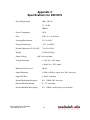
Basic Liquid Crystal Controller
Model D4010 and Model D4010HV
User Manual
Revision 1.01
i
Information in this document is subject to change without notice. Meadowlark Optics
may have patents, patent applications, trademarks, copyrights, or other intellectual
property rights covering subject matter in this document. Except as expressly provided
in any written license agreement from Meadowlark Optics, the furnishing of this
document does not give you any license to these patents, trademarks, copyrights, or
other intellectual property. Please contact Meadowlark Optics for a list of applicable
patents, trademarks, and/or copyrights.
Printed in the United States of America.
This document supports firmware versions 1.00 and 1.01.
Copyright © 2010 Meadowlark Optics, Inc. All rights reserved.
Basic Liquid Crystal Controller
User Manual rev. 1.01
ii
Warranty Summary
Meadowlark Optics, Inc. warrants its products to be free from defects in materials and
workmanship for a period of one year from the date of shipment. If a product proves to be
defective within the warranty period, Meadowlark Optics will provide repair or replacement as
described in the complete warranty policy.
Except as provided in this summary or the applicable Warranty Statement, Meadowlark Optics, Inc.
makes no warranty of any kind, express or implied, including but not limited to any implied
warranty obligation.
Service Assurance
Meadowlark Optics, Inc. now offers Service Assurance to meet your needs. If you have not already
purchased Service Assurance for this product, you may do so at any time during the product’s initial
(one year) warranty period. Service Assurance provides Repair Protection and Calibration
Services to meet your needs.
Repair Protection extends priority repair services beyond the product’s warranty period. You
may purchase up to three years of Repair Protection.
Calibration Services provide annual calibration of your product, recall assurance, and notification
of scheduled calibration. Coverage begins upon registration. You may order up to five years of
Calibration Services.
Service Assurance Advantages
• Costs less than a single repair or calibration
•
Eliminates unexpected service expenses
•
Avoids service delays
For Information and Ordering
For more information or to order Service Assurance, please contact your local Meadowlark Optics,
Inc. representative.
Basic Liquid Crystal Controller
User Manual rev. 1.01
iii
Table of Contents
Warranty Summary................................
iii
General Safety Summary........................
1
Introduction............................................
2
Front Panel Layout ................................
5
Rear Panel Layout ................................
7
Operation ..............................................
8
Liquid Crystal Device Operation ...........
11
Appendix A: Maintenance ....................
12
Appendix B: D4010 Specifications .......
13
Appendix C: D4010HV Specifications..
14
Appendix D: Troubleshooting...............
15
Basic Liquid Crystal Controller
User Manual rev. 1.01
iv
General Safety Summary
Please review the following safety precautions to avoid injury and prevent damage to this product
or any product connected to it. To avoid potential hazards, use this product only as specified.
Note that only qualified Meadowlark Optics, Inc. personnel should perform service procedures.
To Avoid Fire or Personal Injury
When working with your controller and liquid crystal device, always observe the following
precautions:
Use the proper power cord and dc power supply, included with your D4010 Controller. Improper
power cords are often the weak safety link in any electronics system. Care and caution improves
useful system life and safety. Do not use your Meadowlark Optics, Inc. power cord for any other
product.
Always ensure that your Basic Liquid Controller is properly connected to a grounded electrical
outlet which will supply voltage as specified in Appendix B, Specifications.
Do not operate your Basic Liquid Crystal Controller with its cover removed.
Use the proper fuse, as specified in Appendix A, Maintenance.
Always avoid exposed circuitry.
Do not operate your Basic Liquid Crystal Controller with suspected failures with either the
Controller or Liquid Crystal Device.
Never operate your Controller in wet or damp conditions.
Never operate your Controller in an explosive atmosphere.
Always keep product surfaces clean and dry.
Basic Liquid Crystal Controller
User Manual rev. 1.01
1
Introduction
Congratulations on purchasing a Meadowlark Optics Basic Liquid Crystal Controller. This standalone, bench top driver is designed, assembled, and tested to provide you with years of trouble-free
service.
Be sure to familiarize yourself with the contents of this User Manual. While the operation of the
Basic Liquid Crystal Controller is relatively straightforward, understanding the recommended
operating procedures will ensure your Controller operation is safe, easy, and effective.
Liquid Crystal Device Types
For the D4010:
Meadowlark Optics manufactures five liquid crystal (LC) device types:
1)
LC Variable Retarders (compensated and uncompensated, LRC- and LVR-Series)
2)
LC Variable Attenuators (LVA-Series)
3)
LC Polarization Rotators (LPR-Series)
4)
LC Shutters (LCS-Series)
5)
Custom LC optics (contact a Meadowlark representative for information)
Each of our standard device types are available in one, two, and three-inch mounts, with clear
aperture sizes from 0.37 to 1.60 inches diameter.
For the D4010HV:
Meadowlark Optics offers three Swift liquid crystal solutions featuring sub millisecond response
times:
1)
Swift Variable Retarders (compensated and uncompensated, SRC- and SVR-Series)
2)
Swift Optical Shutters (SCS-Series)
3)
Custom Swift LC devices (contact a Meadowlark representative for information)
Basic Liquid Crystal Controller
User Manual rev. 1.01
2
The D4010 controller described in this User Manual is designed to operate each of these liquid
crystal device types (Variable Retarders, Variable Attenuators, Polarization Rotators, LC Shutters
and custom LC devices).
The D4010HV controller described in this User Manual is designed to operate each of these Swift
liquid crystal device types (Swift Variable Retarders, Swift Optical Shutters and custom Swift LC
devices).
Single Channel Controller
Please note that the D4010 and D4010HV are single channel controllers, capable of driving any
single liquid crystal device (D4010) or Swift LC device (D4010HV) listed above. To drive more
than one liquid crystal device, we recommend our Four Channel Digital Interface. To drive more
than one Swift liquid crystal device, we recommend our Two Channel High Voltage Digital
Interface. Please contact Meadowlark Optics for additional information on our Four Channel
Digital Interface, or visit our website at www.meadowlark.com.
The Model D4010 Controller is designed to drive most nematic liquid crystal devices. This
Controller produces a 2 kHz AC square wave output voltage. Voltage is continuously adjustable
from 0 to 20 volts rms. In a Liquid Crystal Variable Retarder, the amplitude of the output voltage
controls the device retardance, the attenuation in a Variable Attenuator, or the angular rotation in a
Polarization Rotator.
The Model D4010HV Controller is designed to drive the Swift LC devices sold by Meadowlark
Optics. This Controller produces a 13kHz AC square wave output voltage. Voltage is continually
adjustable from 0 to 40 volts rms. In a Swift Liquid Crystal Variable Retarder, the amplitude of the
output voltage controls the device retardance, or the state the Swift Optical Shutter.
Two voltage amplitudes can be set on the control panel; switching between them can be controlled
manually or automatically at a modulation frequency set by the user. Modulation between
amplitudes can also be controlled externally by any low voltage square wave or digital signal up to
5 volts.
Quick operation of a Meadowlark Optics Liquid Crystal Cell can be obtained by reading the Liquid
Crystal Device Operation section of this User Manual, starting on page 11.
Basic Liquid Crystal Controller
User Manual rev. 1.01
3
Meadowlark Optics is interested in your comments and suggestions about this Controller and
Manual. Feel free to contact us:
PO Box 1000
5964 Iris Parkway
Frederick, CO 80530
TEL: (303) 833-4333
FAX: (303) 833-4335
e-mail: [email protected]
Basic Liquid Crystal Controller
User Manual rev. 1.01
4
Figure 1 ~ Model D4010 Controller front panel layout
Voltage 1 and Voltage 2 (controls)
The two voltage settings are each continuously adjustable. Output voltages range from 0 to 20 volts
rms for the Model D4010 and 0 to 40 volts rms for the Model 4010HV. Two independent voltage
levels can be tuned and saved.
Internal Frequency (control)
Internal modulation frequency is continuously adjustable from 0.5 – 150 Hz. Can be set and saved
into memory.
Frequency/Voltage 1 (display)
Four-digit, seven-segment, green (D4010) or red (D4010HV) light emitting diode (LED) display,
with wide viewing angle. Displays Voltage Level 1 (in volts) or Internal Frequency (in hertz). As a
user makes an adjustment, that parameter (frequency or voltage) is displayed on Frequency/Voltage
1 display.
Voltage 2 (display)
Four-digit, seven-segment, green (D4010) or red (D4010HV) light emitting diode (LED) display,
with wide viewing angle. Always displays Voltage Level 2, as set by the user. Can be tuned and
saved into memory.
Basic Liquid Crystal Controller
User Manual rev. 1.01
5
Internal/External (switch)
User selectable rocker allows a user to select either Internal or External drive frequency. When
Internal is selected, the controller provides its own drive frequency. Selecting External requires an
External Modulation source is connected via the back panel. External voltage level limited to 5
volts, maximum. Compatible External Modulation frequency ranges from 0.5 – 150 Hz, maximum.
Output Select (switch)
Determines the voltage level that will be output during each half cycle when modulating in both
internal and external modulation modes.
Output Pulse (button)
Pressing this button changes output voltage to the opposite of that selected on the Output Select
Switch; works only when the Modulation Select Switch is set to EXTERNAL.
Error (light)
Red Error indicator light emitting diode (LED) illuminates when a Controller error has been
detected.
Basic Liquid Crystal Controller
User Manual rev. 1.01
6
Figure 2 ~ Model D4010 Controller rear panel layout
Figure 3 ~ Model D4010HV Controller rear panel layout
Power Connector
Input for the 12 volt dc power supply, included.
Power Switch
When the appropriate 12 volt power supply is connected, the Power Switch turns the Controller on
or off.
External Modulation Input
Female BNC connector to accept external signals to control modulation frequency. External
Voltage input up to 2.5 V dc will select LC Voltage Output 1 and voltage input between 2.5 and
5.0 V dc will select LC Voltage Output 2. The valid frequency range for External Modulation is
0.5 to 150 Hz.
Output Connectors
Connects the liquid crystal device being driven to the Controller. For the D4010, output A is
female, for cables terminated with a male SMA connector. Output B is also female, for cables
terminated with a male BNC connector. For the D4010HV, output A is a female Fakra connector,
for Swift LC devices.
Basic Liquid Crystal Controller
User Manual rev. 1.01
7
Operation
Unpack the Basic Liquid Crystal Controller from its shipping container. Check to ensure your
shipment included the following items:
•
•
•
•
Controller (drive) electronics box
DC power supply and power cord
SMA to SMB liquid crystal cable (D4010 only; not included with
D4010HV)
User Manual
Once you have confirmed you received all the components listed above, be sure to inspect each item
carefully for any damage that may have occurred during shipment. Contact Meadowlark Optics,
Inc. immediately if any element of your Controller arrived with noticeable damage.
Connect the 12 V dc power supply to the appropriate connector on the back panel. Turn the power
switch to ON. Connect the cable for a Meadowlark Optics liquid crystal device to the Output
Connector on the back panel. Set up the desired operation of the Controller after becoming familiar
with the controls described in the following paragraphs.
Voltage 1 (control knob)
This control knob sets Voltage 1 by rotating the control knob and watching the display until the
desired voltage is obtained (displayed in volts). Clockwise rotation will increase the voltage up to
the maximum specified voltage while counter clockwise rotation will decrease the voltage down to
a minimum of 0 volts. The displayed voltage may be saved by pressing the control knob for
approximately one second. A brief flash on the display will indicate that the displayed voltage has
been properly saved. The saved voltage may then be recalled at any time by briefly pressing the
control knob.
Voltage 2 (control knob)
This control knob sets Voltage 2 by rotating the control knob and watching the display until the
desired voltage is obtained (displayed in volts). Clockwise rotation will increase the voltage up to
the maximum specified voltage while counter clockwise rotation will decrease the voltage down to
a minimum of 0 volts. The displayed voltage may be saved by pressing the control knob for
approximately one second. A brief flash on the display will indicate that the voltage has been
properly saved. The saved voltage may then be recalled at any time by briefly pressing the control
knob.
Basic Liquid Crystal Controller
User Manual rev. 1.01
8
Internal Frequency (control knob)
Rotating this control knob sets the internal modulation frequency. When the control is rotated the
display that shows Voltage 1 will switch to displaying modulation frequency (in hertz) until either
the Voltage 1 control is rotated or the Internal Frequency control knob has been idle for
approximately three seconds. Clockwise rotation will increase the internal modulation frequency
up to a maximum of 150 Hz while counter clockwise rotation will decrease the internal modulation
frequency down to a minimum of 0.5 Hz. The displayed frequency may be saved by pressing the
control knob for approximately one second. A brief flash on the display will indicate that the
frequency has been saved. If Voltage 1 is being displayed the current internal modulation frequency
may be displayed by briefly pressing the control knob. If frequency is being displayed the saved
frequency may be recalled by briefly pressing the control knob.
Modulation Select (switch)
The Controller can modulate between the two voltages selected via the Output Level Controls. The
Modulation Select Switch determines whether modulation frequency is generated by the controller
(INTERNAL) or an external device (EXTERNAL). If INTERNAL modulation is selected the
output will be modulated between Voltage 1 and Voltage 2 at the frequency set by the Modulation
Frequency Control. To use an external device to control modulation frequency, set the Modulation
Select Switch to EXTERNAL and connect the external device to the External Modulation
Connector on the back panel. The incoming signal can be a square wave of 0 – 5 volts, or a digital
logic signal from a function generator, computer, or other device. The valid frequency range for
External Modulation is 0.5 to 150 Hz.
Output Select (switch)
This switch determines the voltage that will be output during each half cycle when modulating in
either modulation mode. If the Modulation Select Switch is set to INTERNAL, during the first half
of the internal modulation cycle the controller will output the voltage that is selected by the Output
Select Switch. During the second half of the internal modulation cycle the controller will output
the OPPOSITE voltage that is selected by the Output Select Switch. If the Modulation Select
Switch is set to EXTERNAL, a low level on the External Modulation Connector will cause the
controller to output the voltage that is selected by the Output Select Switch. A high level will cause
the controller to output the OPPOSITE voltage that is selected by the Output Select Switch.
Output Pulse (push button)
This button can be used to manually control modulation. To use manual modulation, set the
Modulation Select Switch to EXTERNAL and the Output Select Switch to the desired output
voltage. Pressing the pulse button will switch to the other output voltage for as long as the button is
held down.
.
Basic Liquid Crystal Controller
User Manual rev. 1.01
9
Configuration Recall
When the Controller is powered off, the current voltages and modulation frequency are saved
When the Controller is powered on the values will be restored and applied. The power down saved
values are independent of the values that are saved by pressing the Voltage 1, Voltage 2, and
Internal Frequency control knobs. Those values are also saved through power cycles and can be
recalled at any time by briefly pressing the appropriate control knob.
The output of the Controller is grounded so precautions for chassis ground on the liquid crystal
device are necessary. If the liquid crystal device is to be grounded, allow an electrical connection
to ground to exist only at the liquid crystal device lead that is connected to the connector shells and
cable shield. Please feel free to contact Meadowlark Optics with any questions.
Basic Liquid Crystal Controller
User Manual rev. 1.01
10
Liquid Crystal Device Operation
Liquid Crystal Variable Attenuator Set-Up
Place your Meadowlark Optics Liquid Crystal Variable Retarder (LCVR) between crossed
polarizers with its fast axis at 45 degrees with respect to the polarizers axes. LCVRs without a
housing will have its fast axis oriented perpendicular to the chord cuts on the glass substrates.
Connect the LCVR cell to the D4010 Controller and turn the unit on as described in the
OPERATION section of this manual. If a Meadowlark Optics Liquid Crystal Variable Attenuator
(LCVA) is being used, the crossed polarizers are already mounted onto the cell.
Using the D4010 or D4010HV Controller
Set the Modulation Select Switch to EXTERNAL. Turn both Voltage 1 and 2 controls clockwise
until the maximum voltage has been obtained. Choose the desired output voltage level via the
Output Select Switch. While watching the transmission through the cell and polarizers, turn the
appropriate Voltage control knob counterclockwise until minimum transmission is obtained (if the
LCVR cell does not have a compensator plate included, completely clockwise will already be the
minimum transmission). Now use the Output Select Switch to select the other output voltage level.
Turn the appropriate Voltage control knob counterclockwise past the minimum transmission and
continue turning until a maximum transmission is obtained. The two Voltage controls are now set at
the operating voltage range of the cell for variable attenuation. The setup can be used as a variable
attenuator using the selected Voltage control to adjust the amount of attenuation.
Liquid Crystal Variable Retarder Set-up
The Meadowlark Optics LCVR cell can also be used as a variable retarder (the LCVA cell cannot).
As the voltage is increased (by turning the Voltage control knob clockwise) the retardance is
decreased. Using the voltages found in the above paragraph (Using The D4010 Controller), the
transmission minimum corresponds to zero waves of retardance (or very near zero, if a compensator
plate is not included) and the transmission maximum is half-wave retardance.
Modulation Features on the D4010 and D4010HV Controllers
The Modulation Select Switch can be switched to INTERNAL and the Modulation Frequency
Control will set the speed at which the D4010 modulates the LCVR or LCVA cell between the two
voltages set by the two Voltage controls. The Modulation Select Switch can be set to EXTERNAL
to use the External Modulation Connector on the back of the controller to switch between the two
voltage levels (such as in syncing the transition to some external event). The voltage level can also
be switched by using the Pulse Button.
Swift Liquid Crystal Operation
Swift LC operation is the same as standard LC operation.
Basic Liquid Crystal Controller
User Manual rev. 1.01
11
Appendix A
Maintenance
Cleaning
Periodically clean the outside of your D4010 Controller box with a soft cloth, using a mild cleaning
solution. Do not allow the solution to seep into the controls.
Fuse Replacement
Replacing the fuse on your D4010 Controller requires a few basic components and can be
completed in just a few minutes. Your Basic Liquid Crystal Controller has been designed to
facilitate simple and easy fuse replacement.
Required materials:
A)
Standard tip (blade) screwdriver
B)
250 V ac, 2 A, fast blow fuse
To replace the fuse, follow these simple steps:
1)
Unplug the D4010 Controller. Disconnect the 12-volt power supply from its back panel
connection.
2)
Using a standard tip screwdriver, rotate the fuse holder counterclockwise a quarter-turn.
Note the spring-loaded fuse holder will automatically eject the fuse cartridge, for easy
removal from the back panel.
3)
Remove the fuse from its cartridge. Insert your new fuse into the reusable fuse cartridge.
Take care to prevent damage to the electrical connections.
4)
Insert the fuse cartridge into the fuse holder in the back panel of your Controller.
5)
While lightly pushing the fuse cartridge in, rotate the cartridge clockwise a quarter-turn
using your standard tip screwdriver.
6)
Reconnect the 12-volt power supply to its back panel connection. Plug the power
supply into an appropriate electrical outlet.
Basic Liquid Crystal Controller
User Manual rev. 1.01
12
Appendix B
Specifications for D4010
Power Requirements:
100 – 240 V ac
47 – 63 Hz
500 mA
Power Consumption:
5W
Fuse:
250 V ac, 2 A, fast blow
Operating Environment:
0° C to +50° C
Storage Environment:
-55° C to +100° C
External Dimensions (W x D x H):
7.0 x 5.0 x 3.0 in.
Weight:
1.92 lbs (0.87 kg)
Output Voltage:
± 20 V rms, maximum
Voltage Resolution:
± 1 mV for < 10 V output
± 10 mV for ≥ 10 V output
Maximum Current Load:
20 mA
Output Frequency:
2 kHz ± 5 Hz ac square wave, 50% duty cycle
Output DC Bias:
± 5 mV, maximum
Internal Modulation Frequency:
0.5 – 150 Hz, 50% duty cycle
External Modulation Input:
0 – 5 V, maximum
External Modulation Frequency:
0.5 – 150 Hz, variable duty cycle allowable
Basic Liquid Crystal Controller
User Manual rev. 1.01
13
Appendix C
Specifications for D4010HV
Power Requirements:
100 – 240 V ac
47 – 63 Hz
500 mA
Power Consumption:
10 W
Fuse:
250 V ac, 2 A, fast blow
Operating Environment:
0° C to +50° C
Storage Environment:
-55° C to +100° C
External Dimensions (W x D x H):
7.0 x 5.0 x 3.0 in.
Weight:
2.10 lbs (0.95 kg)
Output Voltage:
± 40 V rms, maximum
Voltage Resolution:
± 1 mV for < 10 V output
± 10 mV for ≥ 10 V output
Maximum Current Load:
80 mA
Output Frequency:
13 kHz ± 10 Hz ac square wave, 50% duty cycle
Output DC Bias:
± 50 mV, maximum
Internal Modulation Frequency:
0.5 – 150 Hz, 50% duty cycle
External Modulation Input:
0 – 5 V, maximum
External Modulation Frequency:
0.5 – 150 Hz, variable duty cycle allowable
Basic Liquid Crystal Controller
User Manual rev. 1.01
14
Appendix D
Troubleshooting
While every effort has been made to prevent system errors, occasionally a system error is detected.
These errors are indicated with “Err” on Display 1 and a number (from 1-5) is shown on Display 2.
Potential error messages are listed below.
Error messages 1-4:
Indicate processor level faults or failures.
Error message 5:
Indicates dc offset above the specified limit. This error will also trigger the
red LED to illuminate. Never operate your liquid crystal device with this
excessive dc offset error. Even small amounts of dc offset can cause
permanent damage to your liquid crystal device.
When any error message is observed, please contact your local Meadowlark Optics, Inc.
representative to obtain a Return Materials Authorization (RMA) number to return your D4010
Controller for service and repair.
Appendix A, Maintenance includes a description of the fuse replacement procedure. Other than
fuse replacement, there are no user serviceable parts.
Basic Liquid Crystal Controller
User Manual rev. 1.01
15