1
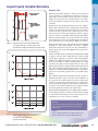
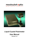
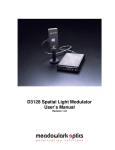
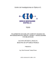
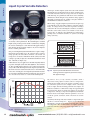
Polarizers
Liquid Crystal Variable Retarders
Anisotropic nematic liquid crystal molecules form uniaxial
birefringent layers in the liquid crystal cell. An essential feature
of nematic material is that, on average, molecules are aligned
with their long axes parallel, but with their centers randomly
distributed as shown in figure 4-6(a). With no voltage applied,
the liquid crystal molecules lie parallel to the glass substrates
and maximum retardation is achieved.
T hese products all use nematic liquid crystal materials to
electrically control polarization. Meadowlark Optics standard
liquid crystal products provide tunable retardation by changing
the effective birefringence of the material with applied voltage,
thus altering the input polarized light to any chosen elliptical,
linear or circular polarization.
Our precision Liquid Crystal Variable Retarders require unique
fabrication and assembly steps. We construct these retarders
using optically flat fused silica windows coated with our
transparent conductive Indium Tin Oxide (ITO). Our ITO
coating is specially designed for maximum transmission from
450 - 1800 nm (see Figure 4.5).
A thin dielectric layer is applied over the ITO and gently rubbed,
to provide for liquid crystal molecular alignment. Two windows
are then carefully aligned and spaced a few microns apart. The
cavity is filled with birefringent nematic liquid crystal material.
Electrical contacts are attached and the device is environmentally
sealed. We carefully place the Liquid Crystal Variable Retarder
in an anodized aluminum housing such that the fast and slow
axes are both at 45° relative to a convenient mounting hole.
Fig. 4-5 Typical transmission through an uncoated liquid
crystal device
48
Fused Silica
ITO
Alignment Layer
Spacer
LC Molecules
(a) Maximum Retardance (V = 0)
LC Molecules
tipped with
applied voltage
(b) Minimum Retardance (V >> 0)
Fig. 4-6 Liquid Crystal Variable Retarder construction
showing molecular alignment (a) without and (b)
with applied voltage
We achieve zero (or any custom) retardance with a
subtractive fixed polymer retarder, called a compensator,
attached to the liquid crystal cell. Negative retardance values
are sometimes preferred, for example, when converting
between right- and left-circularly polarized states. Figure 4-8
illustrates retardance as a function of voltage for a typical Liquid
Crystal Variable Retarder with and without an attached
compensator. Placing a compensated Liquid Crystal Variable
Retarder between two high extinction polarizers creates an
excellent optical attenuator, with convenient electronic
control.
Liquid Crystal
Controllers
Liquid Crystal Devices
Mounting Hardware
Retarders
When voltage is applied, liquid crystal molecules begin to tip
perpendicular to the fused silica windows as shown in figure
4-6(b). As voltage increases, molecules tip further causing a
reduction in the effective birefringence and hence, retardance.
Molecules at the surface, however, are unable to rotate freely
because they are pinned at the alignment layer. This surface
pinning causes a residual retardance of ~30 nm even at high
voltage (20 volts).
As with any anisotropic material, retardance is dependent upon
thickness and birefringence. Liquid cr ystal material
birefringence depends on operating wavelength, drive voltage
and temperature. The overall retardance of a liquid crystal cell
decreases with increasing temperature (approximately -0.4%
per ºC).
www.meadowlark.com • (303) 833-4333 • [email protected]
Liquid Crystal Variable Retarders
Liquid Crystal Variable Retarder response time depends on
several parameters, including layer thickness, viscosity,
temperature, variations in drive voltage and surface treatment.
Liquid crystal response time is proportional to the square
of the layer thickness and therefore, the square of the total
retardance.
a)
Response time improves by using custom materials with high
birefringence and a thinner liquid crystal layer. At higher
temperature, material viscosity decreases, also contributing to a
faster response. For speed critical applications, see page 56 for
Swift LC devices.
Our standard Liquid Crystal Variable Retarders provide a
minimum retardance range of ~30 nm to at least half-wave at
the specified wavelength. With an attached compensator,
retardance is guaranteed to range from zero to at least half-wave
at the specified wavelength. Custom retardance ranges (up to
a few waves) and custom compensators are available. Contact
our Sales Department to discuss your requirements.
b)
QUESTION
Liquid Crystal
Controllers
Each Liquid Crystal Variable Retarder is supplied with retardance
versus voltage performance data for your specified wavelength.
A coaxial cable with mating connector is provided for easy
attachment to one of our electronic controllers.
Liquid Crystal Devices
Another technique involves the Transient Nematic Effect (TNE)
to improve response times. With this drive method, a high
voltage spike is applied to accelerate the molecular alignment
parallel to the applied field. Voltage is then reduced to achieve
the desired retardance. When switching from low to high
retardance all voltage is momentarily removed to allow the
liquid crystal molecules to undergo natural relaxation. Response
time achieved with the transient nematic effect is also shown
in figure 4-7c. Our Four Channel Digital Interface described on
pages 60-61 conveniently provides the necessary TNE voltage
profiles.
Mounting Hardware
Fig.4-7 Temporal response of LC Variable Retarder
The applied voltage is a 2 kHz square wave.
Excessive DC voltage will damage the liquid crystal
Retarders
Response time also depends upon direction of the retardance
change. If the retardance increases, response time is determined
solely by mechanical relaxation of the molecules. If retardance
decreases in value, response time is much faster due to the
increased electric field across the liquid crystal layer. Typical
response time for our standard visible Liquid Crystal Variable
Retarder is shown in figure 4-7b. It takes about 5 ms to switch
from one-half to zero waves (low to high voltage) and about 20
ms to switch from zero to one-half wave (high to low voltage).
Polarizers
Response Time
“The temporal response of a liquid-crystal device
seems very complicated. Where can I find some
clarification?”
ANSWER
Fig.4-8
Liquid Crystal Variable Retarder performance
versus applied voltage at 632.8 nm, 21° C.
(a) without compensator and
(b) with compensator
See our Application Note on temporal response of
liquid crystal devices at www.meadowlark.com.
[email protected] • (303) 833-4333 • www.meadowlark.com
49
Liquid crystal devices should be electrically driven with
an AC waveform with no DC component to prevent ionic
buildup which can damage the liquid crystal layer. We
require a 2 kHz square wave of adjustable amplitude for
controlling our Liquid Crystal Variable Retarders (LCVR).
Our Basic Controller and Four Channel Interface described
on pages 59-61 ensure these drive requirements are met.
A temperature sensing and control option can be added to our
LCVRs for accurate controlling of the operating temperature.
The sensor is attached directly to the LCVR substrate, outside
its clear aperture. Without this option, retardance decreases by
approximately 0.2% to 0.3% per °C increase in temperature.
Key Benefits
Fig. 4-9 Model LVR-100 dimensions
All dimensions in inches
Fig. 4-10 Models LVR-200 and LVR-300 dimensions
All dimensions in inches
•
•
•
•
Computer control capability
Temperature control options
Usable from 450 to 1800 nm
Precision non-mechanical retardation control
Liquid Crystal Devices
Mounting Hardware
Retarders
Polarizers
Liquid Crystal Variable Retarders
SPECIFICATIONS
ORDERING INFORMATION
Retarder Material
Nematic liquid crystal
Substrate Material
Optical quality synthetic
fused silica
Wavelength Range
450-1800 nm (specify)
Liquid Crystal
Controllers
Retardance Range
50
Diameter,
D (in.)
Clear
Aperture, CA
(in.)
Thickness
t (in.)
Part
Number
Without Attached Compensator (30 nm to λ/2)
1.00
0.37
1.23
LVR - 100
~30 nm to λ/2
0 to λ/2
custom ranges are available
2.00
0.70
0.75
LVR - 200
3.00
1.60
1.00
LVR - 300
Transmitted Wavefront
Distortion (at 632.8 nm)
≤ λ/4
1.00
0.37
1.23
LRC - 100
Surface Quality
40-20 scratch and dig
2.00
0.70
0.75
LRC - 200
Beam Deviation
≤ 2 arc min
3.00
1.60
1.00
LRC - 300
Reflectance (per surface)
≤ 0.5% at normal incidence
Diameter Tolerance
± 0.005 in.
Temperature Range
0° C to 50°C
We offer standard liquid crystal variable retarders to cover
four spectral regions:
VIS: 450 - 700 nm IR 1: 650 - 950 nm
IR 2: 900 - 1250 nm IR 3: 1200 - 1700 nm
Recommended Safe
Operating Limit
500 W/cm2, CW
300 mJ/cm2, 10 ns, visible
Please specify spectral region when placing your order.
For temperature control option, append-TSC to part number .
Without compensator
With compensator
With Attached Compensator (0 nm to λ/2)
www.meadowlark.com • (303) 833-4333 • [email protected]
NEW
Basic
B
asic Liqu
Liquid Crystal Controller
•
•
•
Internal
Frequency/Voltage 1
Voltage 1
7.000
Voltage 1
Output
Each Meadowlark Optics Liquid Crystal Variable Retarder is
supplied with a plot of its actual retardance versus voltage. Using
your Model D4010 Controller and this retardance plot ensures
accurate retardance to voltage correlation.
Frequency
Internal
Voltage 2
Pulse
SPECIFICATIONS
Voltage 2
Voltage 2
1.500
Error
Basic Liquid Crystal Controller
Model D4010
Fig. 5-1 Model D4010 Basic Liquid Controller front panel
layout
With a Liquid Crystal Variable Retarder, manual adjustment of the
voltage amplitude controls the device retardance. Figure 4-8 on
page 49 illustrates the relationship between voltage and
retardance.
Independent voltage settings allow easy and repeatable selection
of two retardance values. Often, it is desirable to modulate
between the two states. For example, switching between quarterwave and half-wave retardance changes linearly polarized light
to either left or right circular. A manual toggle allows easy
switching between two states.
0 to 20 V rms, maximum
Voltage Resolution
± 1 mV for < 10 V output
± 10 mV for ≥ 10 V output
Fundamental Drive Waveform
2 kHz ac square wave
External Modulation (input)
TTL compatible
5 V maximum
Output Bias
± 5 mV dc, maximum
Power Requirements
100 – 240 V ac
47 – 63 Hz
500 mA
Internal Frequency (modulation)
0.5 – 150 Hz
50% duty cycle
External Frequency (modulation)
DC – 500 Hz, variable duty
cycle allowable
External Dimensions (W x D x H)
7.0 x 5.0 x 3.0 in.
CE Compliance
Compliant
Liquid Crystal
Controllers
Meadowlark Optics is excited to announce the release of the
Model D4010, our new Basic Liquid Crystal Controller. This
liquid crystal (LC) driver is designed to integrate with any single
(standard) Meadowlark Optics LC device currently offered as
well as any nematic Liquid Crystal device compatible with the
specifications listed. Digital LED voltage and frequency readouts
provide added convenience. Now, frequency and voltage settings
can be easily stored by simply pressing the adjustment knob.
Also, system memory retains voltage and frequency settings at
power down.
Output Voltage
Liquid Crystal Devices
External
Mounting Hardware
Model D4010 comes equipped with its own internal modulation
control. The Internal Frequency knob adjusts periodic switching
between the two voltage settings. An external input allows
modulation to run synchronously with other equipment.
Retarders
•
•
•
•
•
•
•
•
Convenient, stand-alone bench top operation
Versatile - compatible with all standard
Meadowlark Optics LC devices and other nematic liquid
crystal devices with compatible listed specifications
System memory retains voltage and frequency settings
at power down
Bright green, digital LED voltage and frequency readouts
SMA and BNC outputs, with no adapters required
Voltage and frequency save and restore function
Out-of-the-box functionality. Sets up in minutes.
Safe, low voltage operation. Fuse protected.
Intuitive operation. Compact. Easy to use.
ROHS and CE compliant
Low DC bias protects liquid crystal
Polarizers
Key Benefits:
ORDERING INFORMATION
Basic LC Controller
D4010
Two year and three year extended warranty options available,
please contact your Meadowlark Optics sales engineer
[email protected] • (303) 833-4333 • www.meadowlark.com
59
Polarizers
Four Channel Digital Interface
Key Benefits:
•
•
•
•
•
The Four Channel Digital Interface is designed for high
precision computer control of up to four Meadowlark Optics
nematic liquid crystal devices at one time and is available in
either Basic or Advanced Package options.
The D3040 Basic comes with CellDRIVE 3000 Basic software
to allow independent control of the amplitude of the 2 kHz
square wave drive for four separate nematic liquid crystal
cells.
Liquid Crystal
Controllers
Liquid Crystal Devices
Mounting Hardware
Retarders
•
USB or RS232 interface
C++ code examples including .dll libraries
Compact and simple to use
Microsoft® HyperTerminal configuration file included
Independent control of voltage levels on four
channels to 1 mV resolution
Includes National Instruments LabVIEW™ Virtual
Instrument drivers to interface with custom software
The D3050 Advanced Package includes all the functionality of
the Basic Package plus the added features of the CellDRIVE 3100
Advanced software and capability for temperature monitoring
and control on one channel. The Advanced Package allows the
amplitude of the 2 kHz square wave output to be driven either
by an external DC analog signal supplied to a front panel connector or specific CellDRIVE generated waveforms including
sinusoidal, square, triangle, sawtooth and transient nematic
effect waveforms. Additional functions include the capability
to output a sync pulse on a front panel connector at desired
points in the CellDRIVE generated waveforms and the ability
to save/restore all CellDRIVE settings to/from a file.
Fig. 5-2 Basic D3040 operation enables computer control
for up to four Liquid Crystal Variable Retarders
Fig. 5-3 Advanced D3050 operation can accommodate an
external modulation signal via a convenient front
panel connection
60
www.meadowlark.com • (303) 833-4333 • [email protected]
Four Channel Digital Interface
2 kHz ac square wave
Modulation Amplitude
0-10 V rms
Modulation Resolution
1 mV
(0.155 mV using LabVIEW™
subroutines)
DC Offset
< 5 mV
Communications Interface:
USB or RS232
LC Cell to Controller Connections
SMA-SMB, 2 m cable length
Power Requirements
100 – 240 V ac
47 – 63 Hz
500 mA
CE Compliance
compliant
Dimensions (L x W x H)
9.50 x 6.25 x 1.50 in.
Weight
2 lbs.
Modulation Waveforms
external modulation
input (0-5 V)
sinusoidal
triangle
square
sawtooth
transient nematic effect
TTL, 1 μs pulse, user
specified phase
Sync Output
Liquid Crystal
Controllers
Minimum System Requirements
• PC with Pentium II class processor
• 32 MB RAM
• CD ROM drive
• 20 MB hard drive space
• USB or RS232 COM Port
• Windows™ 98/ME/2000/XP/Vista
• Use of LabVIEW Instrument Library requires
LabVIEW version 6.1 or higher
NOTES:
1. D3040 Controllers may be upgraded to
D3050 specifications. This upgrade also includes
CellDRIVE 3100. Please contact a Sales Engineer for
more information.
2. Previous generations of Meadowlark LC devices with
TSC option may not be compatible with the TSC
option in the D3050.
3. Previous generations of Meadowlark LC Controllers
used BNC to SMB cables. Adapters and replacement
cables are available. Please contact a Sales Engineer
for assistance.
4. Temperature monitoring and control is only available
on the D3050 and requires a liquid crystal device with
the temperature sensing and control (TSC) option.
Liquid Crystal Devices
Temperature Control (one channel Active heating/passive
only)
cooling to within ± 1° C of
nominal set point
Advanced package includes:
• D3050 Controller Unit with external input
and sync output front panel connectors
• User Manual
• USB and RS232 cables
• Temperature control cable
• LC-Controller interface cable
• Power supply and power cable
• Temperature monitoring and control
• CellDRIVE 3100 Advanced Software
• National Instruments LabVIEW virtual
instruments driver
Mounting Hardware
ADVANCED PACKAGE ONLY
Basic package includes:
• D3040 Controller Unit
• User Manual
• USB and RS232 cables
• Power supply and power cable
• CellDRIVE 3000 Basic Software
• National Instruments LabVIEW™ virtual
instruments driver
Retarders
Fundamental Drive Waveform
Polarizers
SPECIFICATIONS
ORDERING INFORMATION
Basic
D3040
Advanced
D3050
SMA to SMB Cables
SMA-SMB
Two year and three year extended warranty options available,
please contact your Meadowlark Optics sales engineer
[email protected] • (303) 833-4333 • www.meadowlark.com
61