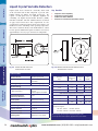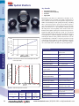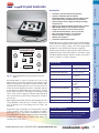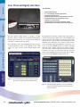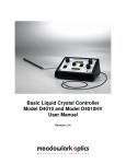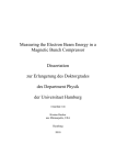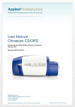
1
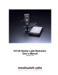
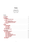
Polarization Control with Liquid Crystals
Liquid crystal retarders can offer outstanding performance over
large incidence angles. Material type, cavity thickness and
especially operating voltage play a large role in determining the
acceptable input angle.
Meadowlark Optics Liquid Crystal Retarders are constructed
using precision polished, optically flat fused silica windows
spaced a few microns apart. The cavity is filled with nematic
liquid crystal material and sealed. This assembly ensures
excellent transmitted wavefront quality and low beam deviation
required for many demanding applications.
Phase control or modulation is possible for light linearly
polarized 45° to the fast axis. Electrical control of the effective
extraordinary index allows precision tuning of an optical phase
delay in the propagating beam.
Retardance
V∼2
δ = λ/2
2<V<4
λ/4 < δ < λ/2
V∼4
δ = λ/4
0 < δ < λ/4
V∼7
δ=0
Fig. 4-1 Output polarization forms for different retardance
values of a compensated variable retarder with
horizontal linearly polarized input
Meadowlark Optics Liquid Crystal Variable Retarders are used
throughout the visible and near infrared region. While these
liquid crystal retarders are affected by temperature and
wavelength changes, they can be calibrated to accommodate
those differences. The resulting Variable Retarder is versatile
across a considerable thermal environment and significant
wavelength range.
Variable attenuators with no mechanical rotation are
configured by placing a Liquid Crystal Variable Retarder
between crossed polarizers. Full 180° linear polarization
rotation can easily be achieved by combining the Liquid Crystal
Variable Retarder with a fixed quarter waveplate.
Spatial Light Modulators consist of individually controllable
pixels. These devices are used in a variety of intensity and/or
phase control applications where spatial variation is required.
Please refer to the Spatial Light Modulator section for details
and specifications on these innovative products.
A Liquid Crystal Variable Retarder is the fundamental
component used in the following devices and systems.
• Variable Attenuators and Rotators
• Variable Beamsplitters
• Spatial Light Modulators
• Non-Mechanical Shutters
• Beam Steerers
• Optical Compensators
• Polarimeters
• Tunable Filters
Liquid Crystal
Controllers
Retardances greater than half-wave can be achieved by using
high birefringent materials and/or increased liquid crystal layer
thickness. Birefringence of liquid crystal materials decreases at
longer wavelengths, requiring proper evaluation and design for
optimum performance.
Continuous tuning of retarders over a broad wavelength range
is required for many applications. This added versatility makes
real-time polarization conversion possible with a single Liquid
Crystal Variable Retarder and electronic controller. Figure 4-1
shows a variety of output polarization forms achieved with a
single device. Pure phase modulation is accomplished by
aligning the optic axis of the liquid crystal retarder parallel to a
linearly polarized input beam.
Liquid Crystal Devices
4<V<7
Output State
Meadowlark Optics Liquid Crystal Variable Retarders provide
precise solid-state retardance tunability. These true zero-order
devices are precision engineered, offering excellent performance
in the visible to near infrared wavelength ranges. When
combined with other optical components, our Liquid Crystal
Variable Retarders produce electrically controllable attenuation,
linear polarization rotation, or phase modulation.
Mounting Hardware
Voltage
Liquid Crystal Variable Retarders
Retarders
The long axis of the liquid crystal molecules defines the
extraordinary (or slow) index. With no voltage present, the
molecules lie parallel to the windows and maximum retardance
is obtained. When voltage is applied across the liquid crystal
layer, the molecules tip toward the direction of the applied
electric field. As voltage increases, the effective birefringence
decreases, causing a reduction in retardance. See Figure 4.6.
Polarizers
Liquid Crystal Variable Retarders are solid state, real-time,
continuously tunable waveplates. Nematic liquid crystals are
birefringent materials whose effective birefringence can be
changed by varying an applied voltage.
NEW
NEW from
fro
r m Meadowlark
Mea
Optics
SSw
wif
iftt Li
LLiquid
Liq
iquid Cry
Swift
Crystal Variable Retarders, see page 56
[email protected] • (303) 833-4333 • www.meadowlark.com
45
Polarizers
Custom Liquid Crystal Capabilities
Retarders
A twisted nematic liquid crystal cell is constructed in the same
manner as a standard LCVR except the alignment of the liquid
crystal molecules is twisted 90°. As in an LCVR, high voltage
(~10 V) aligns the molecules with the field and removes the
birefringence and therefore does not affect the light. At low
voltage, however, the twist does affect the light, causing rotation
of the polarization.
Liquid Crystal
Controllers
Liquid Crystal Devices
Mounting Hardware
Liquid Crystal Variable Retarders
46
A basic building block of Meadowlark Optics line of liquid
crystal products is the Liquid Crystal Variable Retarder (LCVR).
Just one of these devices can replace an entire series of polymer
and standard crystalline retarders. They are electronically
adjustable from nearly zero waves (or less than with an optional
compensator) to over half- wave in the order of 10 milliseconds.
With our new Swift LC technology , the switching speeds are
symmetric and approximately 150 microseconds. An advanced
use of LCVRs is described in the application note “Stokes
Polarimetry Using Liquid Crystal Retarders”, which is available
on our website at www.meadowlark.com.
While we typically list our standard products as the Liquid
Crystal Variable Retarder, Attenuator and Polarization Rotator,
we also have the ability to utilize Liquid Crystals in other ways
that are extremely useful. The Twisted Nematic Liquid Crystal
Device (TN) provides our customers with potential for custom
applications where a standard LCVR might not be appropriate.
At Meadowlark Optics we never cease working on polarization
solutions for our customers. We hope the information below
will provide our customers with new ideas that will challenge
us to create new, exciting solutions for polarization control.
Twisted Nematic Liquid Crystal Cell
One is often only interested in producing two orthogonal
linear polarization states of an optical system, or, in the case of
a digital optical switch, only two states are frequently required.
If you desire to switch the polarization state between only two
angles, for example 0° and 90°, a twisted-nematic device is an
excellent solution. A big advantage of the twisted nematic
device over an LCVR is the simplicity of the driving scheme.
High voltage (above ~10 V) gives 0° rotation and low voltage
(below ~1 V) gives 90° rotation, so you need not concern
yourself with exact voltages or tight tolerances. Also, the field
of view is wide when compared to an LCVR because the cell is
being used in a situation where the optical axis of the liquid
crystal molecules is not at an arbitrary angle to the light but is
either parallel or perpendicular to it.
If the twist is gentle when compared to the wavelength of the
light, the polarization will simply follow the twist of the liquid
crystal molecules. Such a cell is said to be operating in the
“Mauguin limit” and its rotation is quite achromatic. The
polarization rotation angle is equal to the twist angle for all
wavelengths, which are short enough for the twist to be viewed
as sufficiently gentle. When this is not the case, the cell will no
longer act as a pure rotator. The result of inputting linearly
polarized light is no longer an output of rotated linearly
polarized light, but rotated elliptically polarized light. However,
for certain discrete wavelengths, depending on the birefringence
of the liquid crystal and the thickness of the cell, the pure
rotation characteristic is retained.
This concept is illustrated in figure 4-2, which shows the
transmission (normalized to 1), of a 90° twisted nematic cell
between parallel polarizers to be a function of the variable,
U = 2d(b/λ),
where d is the thickness of the cell, b is the birefringence and
λ is the wavelength. Where the curve first goes to zero is
termed the “first minimum” and this position is typically used.
The next highest transmission minimum is called the “second
minimum” and so on. In this plot, moving along the horizontal
axis can be viewed as increasing thickness or decreasing
wavelength.
One might ask, given the achromaticity of thicker cells “why use
the first minimum?” The simple answer is speed. The switching
speed of an LC is a strong function of the cell thickness;
generally, speed drops quadratically with the thickness. Thus,
while a cell operating at a particular wavelength in the first
minimum condition might switch in 10 to 50 ms, one designed
to operate achromatically (for example to transmit <1% between
parallel polarizers) over the entire visible range can take several
seconds to switch.
NEW
NEW from
fro
r m Meadowlark
Mea
Optics
Swift
Crystal Variable Retarders, see page 56
SSw
wif
iftt Li
LLiquid
Liq
iquid Cry
www.meadowlark.com • (303) 833-4333 • [email protected]
Custom Liquid Crystal Capabilities
Polarizers
Figure 4-4 shows the high contrasts of several thousands to one,
which can be achieved in practice with twisted nematic cells.
The curve termed “Normally Black Contrast” was taken between
parallel polarizers where low voltage gives a dark state and high
voltage yields a bright state.The curve termed “Normally White
Contrast” was taken between perpendicular polarizers where
the dark state occurs at high voltage.
Custom sizes are available. Please contact your Meadowlark Optics sales engineer for assistance.
Retarders
0.1
0.08
Transmission
Mounting Hardware
0.1
0.08
0.06
0.06
0.04
0.04
0.02
0
2
4
6
8
10
12
14
Fig. 4-2 Transmission of a twisted-nematic cell between
parallel polarizers as a function of thickness and/or
wavelength
0
0
Fig. 4-3
2
4
6
8
10
12
14
Liquid crystal cell thickness changes
Liquid Crystal Devices
0.02
0
SPECIFICATIONS
Liquid crystal design space
Contrast Ratio
104
1000
100
10
Switching Speed
50 μs to several seconds
Wavelength Range
350 nm-2.2 microns
Retardances
(or phase delay) 0 to 10,000 nm.
Extinction Ratio
Up to 50,000:1 for linear
polarized monochromatic light
Clear Aperture
1 mm to 100 mm
Liquid Crystal
Controllers
10
6
1
1510 1520 1530 1540 1550 1560 1570 1580 1590
Normally White
Contrast
Normally Black
Contrast
Fig. 4-4 Contrast ratio for a twisted nematic liquid
crystal cell
[email protected] • (303) 833-4333 • www.meadowlark.com
47
Polarizers
Liquid Crystal Variable Retarders
Anisotropic nematic liquid crystal molecules form uniaxial
birefringent layers in the liquid crystal cell. An essential feature
of nematic material is that, on average, molecules are aligned
with their long axes parallel, but with their centers randomly
distributed as shown in figure 4-6(a). With no voltage applied,
the liquid crystal molecules lie parallel to the glass substrates
and maximum retardation is achieved.
T hese products all use nematic liquid crystal materials to
electrically control polarization. Meadowlark Optics standard
liquid crystal products provide tunable retardation by changing
the effective birefringence of the material with applied voltage,
thus altering the input polarized light to any chosen elliptical,
linear or circular polarization.
Our precision Liquid Crystal Variable Retarders require unique
fabrication and assembly steps. We construct these retarders
using optically flat fused silica windows coated with our
transparent conductive Indium Tin Oxide (ITO). Our ITO
coating is specially designed for maximum transmission from
450 - 1800 nm (see Figure 4.5).
A thin dielectric layer is applied over the ITO and gently rubbed,
to provide for liquid crystal molecular alignment. Two windows
are then carefully aligned and spaced a few microns apart. The
cavity is filled with birefringent nematic liquid crystal material.
Electrical contacts are attached and the device is environmentally
sealed. We carefully place the Liquid Crystal Variable Retarder
in an anodized aluminum housing such that the fast and slow
axes are both at 45° relative to a convenient mounting hole.
Fig. 4-5 Typical transmission through an uncoated liquid
crystal device
48
Fused Silica
ITO
Alignment Layer
Spacer
LC Molecules
(a) Maximum Retardance (V = 0)
LC Molecules
tipped with
applied voltage
(b) Minimum Retardance (V >> 0)
Fig. 4-6 Liquid Crystal Variable Retarder construction
showing molecular alignment (a) without and (b)
with applied voltage
We achieve zero (or any custom) retardance with a
subtractive fixed polymer retarder, called a compensator,
attached to the liquid crystal cell. Negative retardance values
are sometimes preferred, for example, when converting
between right- and left-circularly polarized states. Figure 4-8
illustrates retardance as a function of voltage for a typical Liquid
Crystal Variable Retarder with and without an attached
compensator. Placing a compensated Liquid Crystal Variable
Retarder between two high extinction polarizers creates an
excellent optical attenuator, with convenient electronic
control.
Liquid Crystal
Controllers
Liquid Crystal Devices
Mounting Hardware
Retarders
When voltage is applied, liquid crystal molecules begin to tip
perpendicular to the fused silica windows as shown in figure
4-6(b). As voltage increases, molecules tip further causing a
reduction in the effective birefringence and hence, retardance.
Molecules at the surface, however, are unable to rotate freely
because they are pinned at the alignment layer. This surface
pinning causes a residual retardance of ~30 nm even at high
voltage (20 volts).
As with any anisotropic material, retardance is dependent upon
thickness and birefringence. Liquid cr ystal material
birefringence depends on operating wavelength, drive voltage
and temperature. The overall retardance of a liquid crystal cell
decreases with increasing temperature (approximately -0.4%
per ºC).
www.meadowlark.com • (303) 833-4333 • [email protected]
Liquid Crystal Variable Retarders
Liquid Crystal Variable Retarder response time depends on
several parameters, including layer thickness, viscosity,
temperature, variations in drive voltage and surface treatment.
Liquid crystal response time is proportional to the square
of the layer thickness and therefore, the square of the total
retardance.
a)
Response time improves by using custom materials with high
birefringence and a thinner liquid crystal layer. At higher
temperature, material viscosity decreases, also contributing to a
faster response. For speed critical applications, see page 56 for
Swift LC devices.
Our standard Liquid Crystal Variable Retarders provide a
minimum retardance range of ~30 nm to at least half-wave at
the specified wavelength. With an attached compensator,
retardance is guaranteed to range from zero to at least half-wave
at the specified wavelength. Custom retardance ranges (up to
a few waves) and custom compensators are available. Contact
our Sales Department to discuss your requirements.
b)
QUESTION
Liquid Crystal
Controllers
Each Liquid Crystal Variable Retarder is supplied with retardance
versus voltage performance data for your specified wavelength.
A coaxial cable with mating connector is provided for easy
attachment to one of our electronic controllers.
Liquid Crystal Devices
Another technique involves the Transient Nematic Effect (TNE)
to improve response times. With this drive method, a high
voltage spike is applied to accelerate the molecular alignment
parallel to the applied field. Voltage is then reduced to achieve
the desired retardance. When switching from low to high
retardance all voltage is momentarily removed to allow the
liquid crystal molecules to undergo natural relaxation. Response
time achieved with the transient nematic effect is also shown
in figure 4-7c. Our Four Channel Digital Interface described on
pages 60-61 conveniently provides the necessary TNE voltage
profiles.
Mounting Hardware
Fig.4-7 Temporal response of LC Variable Retarder
The applied voltage is a 2 kHz square wave.
Excessive DC voltage will damage the liquid crystal
Retarders
Response time also depends upon direction of the retardance
change. If the retardance increases, response time is determined
solely by mechanical relaxation of the molecules. If retardance
decreases in value, response time is much faster due to the
increased electric field across the liquid crystal layer. Typical
response time for our standard visible Liquid Crystal Variable
Retarder is shown in figure 4-7b. It takes about 5 ms to switch
from one-half to zero waves (low to high voltage) and about 20
ms to switch from zero to one-half wave (high to low voltage).
Polarizers
Response Time
“The temporal response of a liquid-crystal device
seems very complicated. Where can I find some
clarification?”
ANSWER
Fig.4-8
Liquid Crystal Variable Retarder performance
versus applied voltage at 632.8 nm, 21° C.
(a) without compensator and
(b) with compensator
See our Application Note on temporal response of
liquid crystal devices at www.meadowlark.com.
[email protected] • (303) 833-4333 • www.meadowlark.com
49
Liquid crystal devices should be electrically driven with
an AC waveform with no DC component to prevent ionic
buildup which can damage the liquid crystal layer. We
require a 2 kHz square wave of adjustable amplitude for
controlling our Liquid Crystal Variable Retarders (LCVR).
Our Basic Controller and Four Channel Interface described
on pages 59-61 ensure these drive requirements are met.
A temperature sensing and control option can be added to our
LCVRs for accurate controlling of the operating temperature.
The sensor is attached directly to the LCVR substrate, outside
its clear aperture. Without this option, retardance decreases by
approximately 0.2% to 0.3% per °C increase in temperature.
Key Benefits
Fig. 4-9 Model LVR-100 dimensions
All dimensions in inches
Fig. 4-10 Models LVR-200 and LVR-300 dimensions
All dimensions in inches
•
•
•
•
Computer control capability
Temperature control options
Usable from 450 to 1800 nm
Precision non-mechanical retardation control
Liquid Crystal Devices
Mounting Hardware
Retarders
Polarizers
Liquid Crystal Variable Retarders
SPECIFICATIONS
ORDERING INFORMATION
Retarder Material
Nematic liquid crystal
Substrate Material
Optical quality synthetic
fused silica
Wavelength Range
450-1800 nm (specify)
Liquid Crystal
Controllers
Retardance Range
50
Without compensator
With compensator
~30 nm to λ/2
0 to λ/2
custom ranges are available
Diameter,
D (in.)
Clear
Aperture, CA
(in.)
Thickness
t (in.)
Part
Number
Without Attached Compensator (30 nm to λ/2)
1.00
0.37
1.23
LVR - 100
2.00
0.70
0.75
LVR - 200
3.00
1.60
1.00
LVR - 300
With Attached Compensator (0 nm to λ/2)
Transmitted Wavefront
Distortion (at 632.8 nm)
≤ λ/4
Surface Quality
40-20 scratch and dig
Beam Deviation
≤ 2 arc min
Reflectance (per surface)
≤ 0.5% at normal incidence
Diameter Tolerance
± 0.005 in.
Temperature Range
0° C to 50°C
We offer standard liquid crystal variable retarders to cover
four spectral regions:
VIS: 450 - 700 nm IR 1: 650 - 950 nm
IR 2: 900 - 1250 nm IR 3: 1200 - 1700 nm
Recommended Safe
Operating Limit
500 W/cm2, CW
300 mJ/cm2, 10 ns, visible
Please specify spectral region when placing your order.
For temperature control option, append-TSC to part number .
1.00
0.37
1.23
LRC - 100
2.00
0.70
0.75
LRC - 200
3.00
1.60
1.00
LRC - 300
www.meadowlark.com • (303) 833-4333 • [email protected]
Liquid Crystal Variable Attenuators
•
•
•
High contrast ratio
Computer control capability
Continuous control of light intensity
Polarizers
Key Benefits
Meadowlark Optics Liquid Crystal (LC) Variable Attenuator offers
real-time, continuous control of light intensity. Our attenuator
consists of an LC Variable Retarder (with attached compensator)
operating between crossed linear polarizers.
T(θ) = 1/2 [1 - cos(θ)] Tmax
Linear
Polarized
Output
Unpolarized
Input
f
s
Compensated
Liquid Crystal
Variable
Retarder
Exit
Polarizer
Fig. 4-11 Standard Liquid Crystal Variable Attenuator design
uses crossed linear polarizers
Maximum transmission is dependent upon properties of the LC
Variable Retarder as well as the polarizers used in your system.
Figure 4-13 shows the transmission of an LC Variable Attenuator
optimized for use at 550 nm with crossed polarizers. An
unpolarized light source is used for illumination.
Contrast ratio is defined as the maximum transmission (obtained
with the LC cell at half-wave operation) divided by the minimum
transmission (obtained with the LC cell at zero waves). Values
exceeding 1000:1 (see figure 4-14) can be obtained for a single
wavelength by optimizing the applied voltage levels for
minimum and maximum transmission. We guarantee a minimum
contrast ratio of 500:1 at your specified wavelength.
Liquid Crystal Devices
Entrance
Polarizer
45˚
where Tmax is the maximum transmittance when retardance is
exactly one-half wave (or 180º). Figure 4-12 shows transmittance
as a function of applied voltage.
Mounting Hardware
Transmission decreases as the applied AC voltage amplitude
increases (half- to zero-waves retardance). The relationship
between transmittance T and retardance θ (in degrees) for crossed
polarizer configuration is given by:
Retarders
With crossed polarizers, light transmission is maximized by
applying the correct voltage to achieve half-wave retardance from
the LC cell as shown in figure 4-11. Half-wave operation rotates
the incoming polarization direction by 90°, so that light is passed
by the second polarizer. Minimum transmission is obtained with
the retarder operating at zero (or a whole number of) waves.
Liquid Crystal
Controllers
Fig. 4-12 Normalized transmittance of Liquid Crystal
Variable Attenuator with crossed linear
polarizers at a single wavelength
Fig. 4-13 Unpolarized Transmittance as a function of
wavelength for LC Variable Attenuator, optimized
for 550 nm, with polarizers and unpolarized input
[email protected] • (303) 833-4333 • www.meadowlark.com
51
A Liquid Crystal Variable Attenuator can be configured with
high efficiency calcite or beamsplitting polarizers to maximize
light transmittance and increase damage threshold. With a
linearly polarized input beam and a calcite polarizer,
transmittance values exceed 90% at most wavelengths. Very
high contrast ratios, in excess of 5000:1, can be achieved with
custom double attenuators. In this design, two Liquid Crystal
Variable Retarders are combined with three polarizers.
Custom devices for near infrared applications, utilizing
appropriate dichroic polarizers, can also be manufactured.
Please see the section on Polarizers for a selection of available
polarizers.
Our Basic Controller and Four Channel Interface described on
pages 59-61 offer the precision waveforms necessary to obtain
accurate and repeatable intensity control for your application.
SPECIFICATIONS
Retarder Material
Nematic liquid crystal with
Birefringent polymer
Polarizer Material
Dichroic polymer
Substrate Material
Optical quality synthetic
fused silica
Wavelength Range
Visible
Near Infared 1
Near Infared 2
450-700 nm
700-900 nm
900-1550 nm
Contrast Ratio
500:1 at single wavelength
Transmitted Wavefront Distortion
(at 632.8 nm)
≤ λ/4 (each component)
Surface Quality
40-20 scratch and dig
Beam Deviation
≤ 2 arc min
Reflectance (per surface)
≤ 0.5% at normal incidence
Diameter Tolerance
±0.005 in.
Temperature Range
0° C to +50° C
Recommended Safe Operating Limit 1 W/cm2, CW (with dichroic
polarizers)
10,000
Contrast Ratio
Liquid Crystal Devices
Mounting Hardware
Retarders
Polarizers
Liquid Crystal Variable Attenuators
ORDERING INFORMATION
1,000
100
10
Diameter,
D (in.)
Clear
Aperture,CA
(in.)
Thickness
t (in.)
Part
Number
1.00
0.37
1.23
LVA - 100-λ
2.00
0.70
0.75
LVA - 200-λ
3.00
1.60
1.00
LVA - 300-λ
Please specify operating wavelength λ in nanometers when
placing your order.
Liquid Crystal
Controllers
Custom sizes are available.
52
Fig. 4-14 Typical Contrast Ratio of a Liquid Crystal Variable
Attenuator optimized at 550 nm
www.meadowlark.com • (303) 833-4333 • [email protected]
Liquid Crystal Polarization Rotators
•
•
•
•
•
High power capability
High polarization purity
Computer control capability
180 degree polarization rotation
Continuous rotation of linearly polarized light
Polarizers
Key Benefits
Retarders
A quarter-wave retarder converts elliptical polarization formed
by the Liquid Crystal Variable Retarder to linear polarization.
The rotation angle is equal to one-half the retardance change
from the Liquid Crystal Variable Retarder.
Standard Liquid Crystal Polarization Rotators are supplied
without an input polarizer. Input polarization direction must be
precisely aligned for optimum performance. Please call if you
require an input polarizer.
We provide test data including the required voltages
corresponding to polarization orientations from approximately
-40° to approximately 140° rotation in 10° increments. These
measurements are taken at room temperature for your specified
wavelength.
Response time depends upon the desired amount of rotation.
Small rotations have longer response times.
Liquid Crystal Devices
Polarization purity is defined as the ratio of the rotated linear
component to the orthogonal component. A selected rotation
is very sensitive to applied voltage and operating temperature.
On average, polarization purity (or contrast ratio) is better than
150:1.
Mounting Hardware
Our Liquid Crystal Polarization Rotator continuously rotates the
polarization direction of a monochromatic, linearly polarized
input beam. Our design consists of a Liquid Crystal Variable
Retarder combined with a zero-order polymer quarter-wave
retarder. The fast axis of the liquid crystal variable retarder is
oriented at 45° to the slow axis of the quarter-wave retarder.
Linearly polarized input must be parallel to the quarter-wave
retarder slow axis. Polarization rotation is achieved by electrically controlling the retardance of the Liquid Crystal Variable
Retarder, eliminating any mechanical motion.
Liquid Crystal
Controllers
Fig. 4-15 Operation of Liquid Crystal Polarization Rotator showing complete rotation of a linearly polarized input beam
[email protected] • (303) 833-4333 • www.meadowlark.com
53
SPECIFICATIONS
ORDERING INFORMATION
Diameter,
D (in.)
Clear
Aperture, CA
(in.)
Thickness
t (in.)
Part
Number
Optical quality synthetic
fused silica
1.00
0.37
1.23
LPR - 100-λ
Wavelength
450-1800 nm (specify)
2.00
0.70
0.75
LPR - 200-λ
Polarization Rotation
180° or more
3.00
1.60
1.00
LPR - 300-λ
Polarization Purity
150:1 average
Transmittance
> 92% with polarized input
Please specify operating wavelength λ in nanometers when
placing your order.
Transmitted Wavefront
Distortion (at 632.8 nm)
≤ λ/4
Custom sizes are available. Please contact our Sales Department
for a custom quote.
Surface Quality
40-20 scratch and dig
Beam Deviation
≤ 2 arc min
Reflectance (per surface)
≤ 0.5% at normal incidence
Diameter Tolerance
±0.005 in.
Temperature Range
0° C to 50° C
Retarder Material
Nematic liquid crystal with
Birefringent polymer
Substrate Material
Recommended Safe Operating Limit 500 W/cm2, CW
300 mJ/cm2, 10 ns, visible
Liquid Crystal
Controllers
Liquid Crystal Devices
Mounting Hardware
Retarders
Polarizers
Liquid Crystal Polarization Rotators
54
www.meadowlark.com • (303) 833-4333 • [email protected]
NEW
High
H
igh C
Contrast
on
Optical Shutter
Polarizers
Key Benefits
•
•
•
•
Optical quality synthetic
fused silica
Polarizer Material
Dichroic Polymer
Wavelength Range
450-700 nm
Contrast Ratio (average)
1,000:1
Angular Field of View
25° incidence angle with some
reduction above 10°
Closed to open:
Open to closed
5 milliseconds
0.4 milliseconds
≤ λ/2
Surface Quality
60-40 scratch and dig
Reflectance (per surface)
≤ 0.5% at normal incidence
Beam Deviation
≤ 5 arc min
Recommended Safe
Operating Limit
1 W/cm2, CW
Glass Thickness
0.48 — 0.52 inches
Polarization Direction
Vertical on input face, horizontal
on output face
Storage temperature
-20° C to +80° C
Operating temperature
0° C to +50° C
75
75
70
70
65
65
60
60
55
55
50
50
450
450
Fig. 4-16
500
500
550
550
600
600
650
650
Wavelength
Wavelength
700
700
Transmission for Polarized Light
ORDERING INFORMATION
Diameter,
D (in.)
Clear
Aperture,CA
(in.)
Thickness
t (in.)
Part
Number
1.00
0.37
1.23
LCS - 100
2.00
0.70
0.75
LCS - 200
3.00
1.60
1.00
LCS - 300
[email protected] • (303) 833-4333 • www.meadowlark.com
Liquid Crystal
Controllers
Transmitted Wavefront
Distortion (at 632.8 nm)
80
80
Liquid Crystal Devices
Switching Time (10% to 90%) at room temperature
85
85
Polarized Transmission(%)
Substrate Material
Polarized Transmission (%)
Twisted nematic
Mounting Hardware
Liquid crystal configuration
This liquid crystal shutter is a vibration-free alternative to
mechanical shutter that is especially convenient for use in
polarized light beams. The liquid crystal switches between
a state that rotates the input polarization by 90° with no
voltage applied and a state that makes no change in the input
polarization with 8 to 10 volts applied. The applied voltage is
2 kHz AC as supplied by our 4010, 3040 or 3050 liquid crystal
drivers. The liquid crystal configuration is twisted nematic.
The shutter is supplied with integral dichroic visible polarizers
that function over the wavelength range of 450 nm to 700 to
provide an average contrast ratio of better than 1,000:1 over
this wavelength range. Shutters with larger aperture sizes and
with wavelength coverage to 2.1 microns are available on a
custom basis. Please call with your special requirements.
Retarders
SPECIFICATIONS
High Contrast
No mechanical motion
Computer control capability
No vibration
55
Polarizers
Swift Liquid Crystal Principles
Meadowlark Optics next generation liquid crystal variable
devices utilizes a new bulk stabilized polymer liquid crystal
formulation. With switching speeds of less than a 150
microseconds in both directions our new “Swift” Liquid Crystal
devices are perfect for applications where response time is
critical.
Liquid crystal polymer composite materials have been studied
extensively is the past decades because of their intriguing
physics and their potential application in robust, fast-switching
liquid crystal devices. Meadowlark Optics has developed a novel
fabrication process in which a polymer network is utilized to
enhance the electro-optical performance of our liquid crystal
devices.
Mounting Hardware
Retarders
Swift Liquid Crystal Technology
Liquid Crystal Devices
(a)
As cell gap increases, switching times increase as the square of
the thickness. This effect is due to molecular properties of the
bulk liquid crystal material and the alignment layer of the cell
(See Figure 4-6). The actual temporal electro-optical response
of the cell has two components, (1) a very fast surface layer
effect that occurs very close to the alignment layer and is on the
order of microseconds and (2) a relatively slow response that
occurs in the bulk of the material on the order of milliseconds.
This second response dominates in a typical bulk liquid crystal
device. Figure 4-17 (a) defines these two regions for a standard
liquid crystal variable retarder cell. To overcome this effect the
introduction of small amounts of polymer material into the bulk
allow for a multitude of alignment surfaces for the liquid crystal
material. This allows for alignment surface effects throughout
the bulk of the cell (Figure 4-17 (b)). The addition of a polymer
stabilizing material in the bulk essentially decouples the cell
gap from the switching speed. The challenge to this type of
device is now there are no means for uniform liquid crystal
alignment in the bulk, such that after infiltration of polymer
material; the liquid crystal is aligned in random fashion with
no particular “fast-axis” for functional retarder devices. For
liquid crystal alignment to occur Meadowlark Optics performs
a mechanical shearing process on the devices that aligns the
bulk liquid crystal material (Figure 4-17 (c)). Once this step
is performed the cell is locked into place and sealed. This
assembly process ensures excellent uniformity in alignment of
the liquid crystal molecules and gives a retardance uniformity
across the clear aperture of less than 20nm.
Meadowlark Optics Swift liquid crystal technologies can be
used throughout the visible and near infrared region. While
these devices, like all liquid crystal devices, are affected by
temperature and wavelength changes, they can be calibrated
to accommodate those differences. Each Swift liquid crystal
variable retarder is supplied with retardance versus voltage
performance data for your specified wavelength, while our
shutter devices are provided with temporal performance data.
A coaxial cable with mating connector is provided for easy
attachment to one of our new high voltage power supply
sources.
(b)
Liquid Crystal
Controllers
Typical bulk liquid crystal devices, such as Meadowlarks’LCVR,
have response times that are governed by the bulk of the liquid
crystal and are a function of cell gap.
(c)
Fig. 4-17
(a) Typical bulk liquid crystal device showing both
regions of fast and slow electro-optical
response.
(b) A polymer stabilized liquid crystal device
showing random alignment in the bulk of the
material.
(c) A Swift Liquid Crystal device after alignment
process.
56
www.meadowlark.com • (303) 833-4333 • [email protected]
NEW
SSwift
wift Liqu
Liquid Crystal Variable Retarders
Polymer stabilized nematic
liquid crystals
0.8
Substrate Material
Optical quality synthetic
fused silica
0.6
Response Time (10-90%)
≤ 175 μs (zero to half-wave)
≤ 175 μs (half-wave to zero)
0.4
Contrast Ratio
150:1, minimum
Retardance Range
0.2
0.0
250
Without compensator
With compensator
300
350
400
450
500 900
~50 nm to λ/2
0 to λ/2
custom ranges are available
1000 1100 1200 1300 1400 1500
Time (μs)
(Ps)
Time
≤ λ/2
Surface Quality
40-20 scratch and dig
Beam Deviation:
≤ 2 arc min
Reflectance (per surface):
≤ 0.5% at normal incidence
Diameter Tolerance
± 0.005 in.
Storage Temperature
-20° C to 80° C
Operating Temperature
0° C to 55° C
Wavelength Range
VIS:
IR 1:
IR 2:
IR 3:
Liquid Crystal
Controllers
Retardance (nm)
Fig. 4-18 Swift Liquid Crystal Response Time Plot
Transmitted Wavefront
Distortion (at 632.8 nm)
Liquid Crystal Devices
Normalized
Response
Normalized
Response
Retarder Material
Mounting Hardware
SPECIFICATIONS
1.0
Retarders
• Sub-millisecond response times
• Computer control capability
• Temperature control options
• Performance from 450 to 1800 nm
The next generation of liquid crystal variable retarders utilizes
a new bulk stabilized polymer liquid crystal formulation. With
switching speeds of less than a 150 microseconds in both
directions the Swift Liquid Crystal Variable Retarder (SLCVR)
is perfect for applications where response time is critical.
The SLCVRs require a high voltage (< 100 Vrms) 13 kHz
square wave of adjustable amplitude that is provided by our
D3060HV High Voltage Interface (see page 62). A temperature
sensing and control option can be added to our SLCVRs for
accurate controlling of the operating temperature. The thermal
sensor is attached directly to the SLCVR substrate, outside the
clear aperture. Custom SLCVRs are available for a variety of
applications.
Polarizers
Key Benefits
450-700 nm
650-950 nm
900-1250 nm
1200-1700 nm
ORDERING INFORMATION
Diameter, D (in.)
Voltage (V)
Clear
Aperture,CA
(in.)
Thickness
t (in.)
Part
Number
Without Attached Compensator (50 nm to λ/2)
2.00
0.70
0.75
SVR - 200
With Attached Compensator (0 nm to λ/2)
Fig. 4-19 Swift Liquid Crystal Retardance vs Voltage
2.00
0.70
0.75
SRC - 200
Please specify spectral region when placing your order.
[email protected] • (303) 833-4333 • www.meadowlark.com
57
NEW
Polarizers
SSwift
wift Optical
Opt
Shutters
Key Benefits
•
•
•
•
Liquid Crystal Devices
Polarized Transmission (%)
Polarized Transmission(%)
Mounting Hardware
Retarders
This liquid crystal shutter is a vibration-free alternative to mechanical shutters for use in high- speed shutter applications. It
uses a Swift LC cell between crossed polarizers to provide submillisecond switching for both opening and closing. Switching
time is 125 microseconds to open and 125 microseconds to
close. The switching times are less than 50 microseconds if the
shutter is heated to 40° C. The D3060HV controller provides
this temperature control capability. These shutters show some
haziness in the liquid crystal layer in the blue and green wavelengths. The light loss from this haze is about 1% at 700 nm but
increases monotonically to about 10% loss at 450 nm. Scatter at
wavelengths above 700 nm is negligible. The shutter is supplied
with integral dichroic visible polarizers that function over the
wavelength range of 450 nm to 700 nm to provide an average
contrast ratio of better than 200:1. Shutters with larger aperture
sizes and with wavelength coverage to 2.1 microns are available
on a custom basis. Please call with your special requirements.
85
80
75
70
65
60
SPECIFICATIONS
55
Retarder Material
Polymer stabilized nematic
liquid crystals
Substrate Material
Optical quality synthetic fused
silica
Polarizer Material
Dichroic Polymer
Wavelength Range
450-700 nm
Contrast Ratio (average)
200:1
Angular Field of View
± 5 ° incidence angle
50
450
500
550
600
Wavelength
[nm]
Wavelength [nm]
650
700
Fig. 4-20 Polarized transmission of the Swift Optical Shutter
in the open state
1.0
1.0
Switching Time (10% to 90%) at room temperature
Closed to open:
Open to closed
Normalized Response
Normalized Response
Liquid Crystal
Controllers
0.8
0.8
150 μs
150 μs
50 μs
0.6
0.6
Switching Time (10% to 90%) at
40° C
0.4
0.4
Transmitted Wavefront
Distortion (at 632.8 nm)
≤ λ/2
Surface Quality
60-40 scratch and dig
Reflectance (per surface):
≤ 0.5% at normal incidence
0.2
0.2
0
0.0
250
300
300
350
400
400
450
500 900 1000 1100 1200 1300 1400 1500
500
900 1100
1300 1500
Time (Ps)
Time (μs)
Fig. 4-21 Swift LC Response Time Plot
ORDERING INFORMATION
58
No mechanical motion
Computer control capability
Noiseless
High speed
Diameter, D (in.)
Clear
Aperture,CA
(in.)
Thickness
t (in.)
Part
Number
2.00
0.70
0.75
SCS - 200
Beam Deviation
≤ 5 arc min
Recommended Safe
Operating Limit
1 W/cm2, CW
300 mJ/cm2, 10 ns, visible
Glass Thickness
0.48 — 0.52 inches
Polarization Direction
Vertical on input face, horizontal
on output face
Storage temperature
-20° C to +70° C
Operating temperature
-10° C to +60° C
www.meadowlark.com • (303) 833-4333 • [email protected]
NEW
Basic
B
asic Liqu
Liquid Crystal Controller
•
•
•
Internal
Frequency/Voltage 1
Voltage 1
7.000
Voltage 1
Output
Each Meadowlark Optics Liquid Crystal Variable Retarder is
supplied with a plot of its actual retardance versus voltage. Using
your Model D4010 Controller and this retardance plot ensures
accurate retardance to voltage correlation.
Frequency
Internal
Voltage 2
Pulse
SPECIFICATIONS
Voltage 2
Voltage 2
1.500
Error
Basic Liquid Crystal Controller
Model D4010
Fig. 5-1 Model D4010 Basic Liquid Controller front panel
layout
With a Liquid Crystal Variable Retarder, manual adjustment of the
voltage amplitude controls the device retardance. Figure 4-8 on
page 49 illustrates the relationship between voltage and
retardance.
Independent voltage settings allow easy and repeatable selection
of two retardance values. Often, it is desirable to modulate
between the two states. For example, switching between quarterwave and half-wave retardance changes linearly polarized light
to either left or right circular. A manual toggle allows easy
switching between two states.
0 to 20 V rms, maximum
Voltage Resolution
± 1 mV for < 10 V output
± 10 mV for ≥ 10 V output
Fundamental Drive Waveform
2 kHz ac square wave
External Modulation (input)
TTL compatible
5 V maximum
Output Bias
± 5 mV dc, maximum
Power Requirements
100 – 240 V ac
47 – 63 Hz
500 mA
Internal Frequency (modulation)
0.5 – 150 Hz
50% duty cycle
External Frequency (modulation)
DC – 500 Hz, variable duty
cycle allowable
External Dimensions (W x D x H)
7.0 x 5.0 x 3.0 in.
CE Compliance
Compliant
Liquid Crystal
Controllers
Meadowlark Optics is excited to announce the release of the
Model D4010, our new Basic Liquid Crystal Controller. This
liquid crystal (LC) driver is designed to integrate with any single
(standard) Meadowlark Optics LC device currently offered as
well as any nematic Liquid Crystal device compatible with the
specifications listed. Digital LED voltage and frequency readouts
provide added convenience. Now, frequency and voltage settings
can be easily stored by simply pressing the adjustment knob.
Also, system memory retains voltage and frequency settings at
power down.
Output Voltage
Liquid Crystal Devices
External
Mounting Hardware
Model D4010 comes equipped with its own internal modulation
control. The Internal Frequency knob adjusts periodic switching
between the two voltage settings. An external input allows
modulation to run synchronously with other equipment.
Retarders
•
•
•
•
•
•
•
•
Convenient, stand-alone bench top operation
Versatile - compatible with all standard
Meadowlark Optics LC devices and other nematic liquid
crystal devices with compatible listed specifications
System memory retains voltage and frequency settings
at power down
Bright green, digital LED voltage and frequency readouts
SMA and BNC outputs, with no adapters required
Voltage and frequency save and restore function
Out-of-the-box functionality. Sets up in minutes.
Safe, low voltage operation. Fuse protected.
Intuitive operation. Compact. Easy to use.
ROHS and CE compliant
Low DC bias protects liquid crystal
Polarizers
Key Benefits:
ORDERING INFORMATION
Basic LC Controller
D4010
Two year and three year extended warranty options available,
please contact your Meadowlark Optics sales engineer
[email protected] • (303) 833-4333 • www.meadowlark.com
59
Polarizers
Four Channel Digital Interface
Key Benefits:
•
•
•
•
•
The Four Channel Digital Interface is designed for high
precision computer control of up to four Meadowlark Optics
nematic liquid crystal devices at one time and is available in
either Basic or Advanced Package options.
The D3040 Basic comes with CellDRIVE 3000 Basic software
to allow independent control of the amplitude of the 2 kHz
square wave drive for four separate nematic liquid crystal
cells.
Liquid Crystal
Controllers
Liquid Crystal Devices
Mounting Hardware
Retarders
•
USB or RS232 interface
C++ code examples including .dll libraries
Compact and simple to use
Microsoft® HyperTerminal configuration file included
Independent control of voltage levels on four
channels to 1 mV resolution
Includes National Instruments LabVIEW™ Virtual
Instrument drivers to interface with custom software
The D3050 Advanced Package includes all the functionality of
the Basic Package plus the added features of the CellDRIVE 3100
Advanced software and capability for temperature monitoring
and control on one channel. The Advanced Package allows the
amplitude of the 2 kHz square wave output to be driven either
by an external DC analog signal supplied to a front panel connector or specific CellDRIVE generated waveforms including
sinusoidal, square, triangle, sawtooth and transient nematic
effect waveforms. Additional functions include the capability
to output a sync pulse on a front panel connector at desired
points in the CellDRIVE generated waveforms and the ability
to save/restore all CellDRIVE settings to/from a file.
Fig. 5-2 Basic D3040 operation enables computer control
for up to four Liquid Crystal Variable Retarders
Fig. 5-3 Advanced D3050 operation can accommodate an
external modulation signal via a convenient front
panel connection
60
www.meadowlark.com • (303) 833-4333 • [email protected]
Four Channel Digital Interface
2 kHz ac square wave
Modulation Amplitude
0-10 V rms
Modulation Resolution
1 mV
(0.155 mV using LabVIEW™
subroutines)
DC Offset
< 5 mV
Communications Interface:
USB or RS232
LC Cell to Controller Connections
SMA-SMB, 2 m cable length
Power Requirements
100 – 240 V ac
47 – 63 Hz
500 mA
CE Compliance
compliant
Dimensions (L x W x H)
9.50 x 6.25 x 1.50 in.
Weight
2 lbs.
Modulation Waveforms
external modulation
input (0-5 V)
sinusoidal
triangle
square
sawtooth
transient nematic effect
TTL, 1 μs pulse, user
specified phase
Sync Output
Liquid Crystal
Controllers
Minimum System Requirements
• PC with Pentium II class processor
• 32 MB RAM
• CD ROM drive
• 20 MB hard drive space
• USB or RS232 COM Port
• Windows™ 98/ME/2000/XP/Vista
• Use of LabVIEW Instrument Library requires
LabVIEW version 6.1 or higher
NOTES:
1. D3040 Controllers may be upgraded to
D3050 specifications. This upgrade also includes
CellDRIVE 3100. Please contact a Sales Engineer for
more information.
2. Previous generations of Meadowlark LC devices with
TSC option may not be compatible with the TSC
option in the D3050.
3. Previous generations of Meadowlark LC Controllers
used BNC to SMB cables. Adapters and replacement
cables are available. Please contact a Sales Engineer
for assistance.
4. Temperature monitoring and control is only available
on the D3050 and requires a liquid crystal device with
the temperature sensing and control (TSC) option.
Liquid Crystal Devices
Temperature Control (one channel Active heating/passive
only)
cooling to within ± 1° C of
nominal set point
Advanced package includes:
• D3050 Controller Unit with external input
and sync output front panel connectors
• User Manual
• USB and RS232 cables
• Temperature control cable
• LC-Controller interface cable
• Power supply and power cable
• Temperature monitoring and control
• CellDRIVE 3100 Advanced Software
• National Instruments LabVIEW virtual
instruments driver
Mounting Hardware
ADVANCED PACKAGE ONLY
Basic package includes:
• D3040 Controller Unit
• User Manual
• USB and RS232 cables
• Power supply and power cable
• CellDRIVE 3000 Basic Software
• National Instruments LabVIEW™ virtual
instruments driver
Retarders
Fundamental Drive Waveform
Polarizers
SPECIFICATIONS
ORDERING INFORMATION
Basic
D3040
Advanced
D3050
SMA to SMB Cables
SMA-SMB
Two year and three year extended warranty options available,
please contact your Meadowlark Optics sales engineer
[email protected] • (303) 833-4333 • www.meadowlark.com
61
NEW
Polarizers
TTwo
wo C
Channel
han
High Voltage Interface
Key Benefits:
•
•
•
•
•
Liquid Crystal
Controllers
Liquid Crystal Devices
Mounting Hardware
Retarders
•
USB or RS232 interface
C++ code examples (all required libraries included)
Compact and simple to use
Microsoft® HyperTerminal configuration file
included
Independent control of voltage levels on two
channels to 10 mV resolution
Includes National Instruments LabVIEW™ Virtual
Instrument drivers to interface with custom
software
SPECIFICATIONS
The Two Channel High Voltage Digital Interface is designed for
high precision computer control of up to two Meadowlark
Optics Swift LC liquid crystal devices at one time.
The D3060HV Package includes all the functionality of the
D3050 plus the high voltage circuitry necessary for Swift LC
devices. CellDRIVE 3100 HV software includes all the features
of the CellDRIVE 3100 Advanced software, but is optimized for
the high-speed Swift LC devices. Also included is capability for
temperature monitoring and control on one channel. The
Advanced Package allows the amplitude of the 13 kHz square
wave output to be driven either by an external signal supplied
to a front panel connector or specific CellDRIVE generated
waveforms including sinusoidal, square, triangle, sawtooth and
transient nematic effect waveforms. Additional functions
include the capability to output a sync pulse on a front panel
connector at desired points in the CellDRIVE generated
waveforms and the ability to save/restore all CellDRIVE settings
to/from a file.
Package includes:
• D3060HV Controller Unit with external input and sync
output front panel connectors
• User Manual
• USB and RS232 cables
• Temperature control cable
• LC-Controller interface cable
• Power supply and power cable
• Temperature monitoring and control
• CellDRIVE 3100 HV Software
• National Instruments LabVIEW virtual instruments driver
Fundamental Drive Waveform
13 kHz ac square wave
Modulation Amplitude
0-100 V rms
Modulation Resolution
10 mV
(1.55 mV using LabVIEW™
subroutines)
DC Offset
< 50 mV
Communications Interface
USB or RS232
LC cell to Controller
Connections
LEMO™ RF cable,
2 m length
Power Requirements
100 – 240 Vac
47 – 63 Hz
2.5 A
Safety Feature
Keyed Interlock Switch
Dimensions (L x W x H)
10.50 x 7.25 x 4.0 in.
Weight
6 lbs.
Modulation Waveforms
external modulation input
(0-5 V)
Sinusoidal
Triangle
Square
Sawtooth
transient nematic effect
Temperature Control (one channel Active heating/passive
only)
cooling to within ± 1° C of
nominal set point
Sync Output
TTL, 1 μs pulse, user
specified phase
Minimum System Requirements
• PC with Pentium II class processor
• 32 MB RAM
• CD ROM drive
• 20 MB hard drive space
• USB or RS232 COM Port
• Windows™ 98/ME/2000/XP/Vista
• Use of LabVIEW Instrument Library requires
LabVIEW version 6.1 or higher
ORDERING INFORMATION
62
High Voltage Controller
D3060HV
High Voltage Cable
Swift LC Cable
www.meadowlark.com • (303) 833-4333 • [email protected]