1
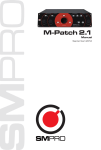
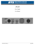
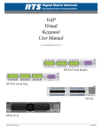
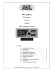
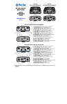
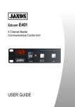
4-Channel Intercom Stations
MS-440, RM-440, SB-440
MS-440*
F E AT U R E S
• Four Independent Intercom Channels
for ultimate flexibility
• Microprocessor-Controlled Logic
assures maximum communications power
• Universal Voltage Power Supply for
90 - 240 VAC operation, with short-circuit
protection on each channel
• Linking Control instantly links channels
together in “super party line”
• Separate Talk and Listen Buttons
for each channel
• Individual Listen Volume Controls
for each channel
• “All-Talk” Function permits instant
communications to all four channels
• Four Separate Program Inputs are
electronically balanced
• Three Interruptible IFB Channels
make talent cueing easy
• “Announce” Button with Relay for
external paging
• Visual “Call Signaling” alerts users when
others want to speak to them
• Wide-Range High-Output Speaker
for optimum clarity in all acoustic environments
• “Hot-Mic” Output allows easy
connection to external IFBs
RM-440*
SB-440*
GENERAL DESCRIPTION
The 440 series is Clear-Com’s most advanced party-line intercom system. Each
station is a four-channel intercom with superior audio and versatile channel access
to provide unmatched communication flexibility. All front-panel controls are intuitive and easy to operate. The station’s front-panel buttons are programmable and
can be customized for a wide variety of applications that will meet the demands of
any stage, studio, or field producer. Separate volume controls for every channel
ensure the perfect audio mix in the headset or on the integral speaker.
The SB-440 includes a versatile switching matrix which allows up to ten different
groups of stations to be assigned to any one of the four channels. A convenient
“link” feature ties all four channels into one giant party line for rehearsal or staff
check. The stations have adjustable mounting ears that can be removed for desktop
operation. The regulated power supply in the MS-440 and SB-440 provides power
for the entire intercom system. These stations have front-panel short-circuit indicators to show if a short has occured on any of the four intercom lines. Other features
include separate audio sources for all intercom channels and three built-in IFB program interrupts for talent cuing.
• Adjustable Mic Proximity
Compensation reduces acoustic
feedback
• Superior “Contoured” Audio insures
excellent voice intelligibility under all noise
conditions, including high-noise environments
®
PROFESSIONAL INTERCOM PRODUCTS
* Shown with optional gooseneck mic
by Clear-Com
4-Channel Intercom Stations
MS-440 Front Panel
1
2
3 4
5 6
7
8 9 10 11 12 13 14
CH. A
15
CH. B
CH. C
16
17
CH. D
Reset˚
Listen
Announce
Power
Mic On
PL
pro
MS-440
Ch A
Intercom
Panel Mic
Talk
On
Ch B
All Talk
Off
Panel
Ch C
Speaker
Call
Headset
Mic Select
Ch D
Short
Link On
HeadSet
4-Channel
Main Station
Short
(Off)
(Default)
Panel Mic Sidetone
Gain
Adjust
18
On
Long
B C D
A B C D
PROGRAM AUTO CALL
INTERRUPT
A B C D
A B C D
AUTO-TALK TALK LATCH
LISTEN
DISABLE
PROGRAM
LEVEL
19 20 21 22 23 24 25
A B C D
PROGRAM
SELECT
Listen
10. ANNOUNCE BUTTON
Instantly restores operation in
the event of a DC power short.
Directs the station’s mic signal
to a dedicated rear-panel
“Announce” output, while
simultaneously activating an
associated relay.
Illuminates to indicate when
power is on.
11. LISTEN BUTTON
3. HEADSET CONNECTOR
XLR 4-pin male
4. PANEL MIC CONNECTOR
Allows easy attachment of proprietary 9" or 18" gooseneck
microphone.
Turns on the LISTEN circuit on
the corresponding intercom
channel, allowing the user to
hear activity on that channel.
12. LISTEN LED INDICATOR
Illuminates when the channel’s
LISTEN circuit is on.
5. MIC ON SWITCH
Activates the gooseneck or
headset mic.
6. MIC ON INDICATOR
LED Illuminates when the
microphone is active.
7. MIC SELECT SWITCH
Selects between the panelmounted gooseneck mic and
the headset mic.
8. LINK BUTTON
Instantly links channels B, C,
and/or D to Channel A, creating a “Super Party-Line”.
13. TALK BUTTON WITH
BUILT-IN CALL LIGHT
These illuminated dual-action
buttons light up to indicate
the on-off status of each
channel’s TALK circuit.
Translucent labels can be
installed behind the key caps
for easy identification.
These buttons also function
as attention-getting “Call”
lights. When the “Call” button is pressed at another station, this button flashes to
attract your attention.
14. CALL BUTTON
9. ALL TALK BUTTON
Sends the station’s mic signal
to all four channels, regardless
of whether those channels are
currently assigned.
Prgm
Listen
Null
CH B
Prgm
Listen
Null
Prgm
Listen
CH C
Null
Activates all station and beltpack call lights on the respective intercom channel.
15. VOLUME CONTROL
Adjusts the listening level for
both speaker and headset.
Prgm
CH D
26 27 28 29
1. RESET SWITCH
2. POWER INDICATOR
Null
CH A
A B C D
LINE
LENGTH
31
30
16. SPEAKER ON/OFF
SWITCH
Selects or deselects the
built-in speaker.
Call
1
2
3
4
5
6
7
8
9
10
Off
A
B
C
D
PartyLine
17. LOUDSPEAKER
High-quality loudspeaker is
driven by a four-watt proaudio amplifier.
18. SHORT INDICATORS
These indicators will illuminate
when there is a short detected on one or more of the
intercom lines. Power will
continue to be supplied to the
other intercom channels.
19. PANEL MIC GAIN
Adjusts the sensitivity of the
gooseneck panel mic.
21. AND 22. ARE BOTH ON.
Allows program interrupt (IFB)
from any RM-440 station in
the system.
23. AUTO-TALK/LISTEN
SELECT
Allows the TALK and LISTEN
circuit to be automatically activated when the TALK button
is depressed.
21. PROGRAM INTERRUPT
SELECT (IFB)
Selects which intercom channels that the program interrupt will operate on. The
audio program source will be
interrupted when the TALK
button is pushed.
22. AUTO CALL SELECT
Sends a call signal automatically when the TALK button
is depressed.
Adjusts the listen level for
each intercom channel.
28. NULL CONTROL
Used in conjunction with
line/link switch (#30) to minimize intercom channel crosstalk in station.
29. PROGRAM ADJUST
20. SIDETONE ADJUST
Controls the level of your
voice as it is heard in your
own headset and speaker.
27. LISTEN LEVEL
CONTROL
24. LATCH DISABLE
SELECT
TALK button is momentary
function only.
25. PROGRAM LEVEL
Adjusts the level of the Audio
Program feed to the station
speaker.
Controls the level of program
audio sent out to each individual channel
30. LINE LENGTH SELECT
DIP SWITCH
Compensates for electrical
capacitance on each individual
intercom channel to optimize
null adjust.
26. PROGRAM SELECT
Determines which intercom
channels the audio program
feed will be sent to.
31. MATRIX ASSIGNMENT
SWITCH (SB-440 ONLY)
Allows you to assign an intercom station to any one of the
four channels. It also allows
the station to be assigned to
an off or party-line position.
4-Channel Intercom Stations
MS-440 Rear Panel
33
32
33
34
CHANNEL A
34
CHANNEL C
ON
ON
OFF
OFF
PROGRAM INPUT
HOT MIC/IFB
TO MA-4
ON
TERM.
90 / 240VAC
60 / 50Hz
80 VA (MAX)
37 38
35 36
TERM.
OFF
OUTPUT: 30VDC
1.75A MAX
CLASS 2 WIRING
WARNING: TO REDUCE THE
RISK OF FIRE OR ELECTRIC SHOCK
DO NOT EXPOSE THIS EQUIPMENT
TO RAIN OR MOISTURE.
ON
RISK OF ELECTRIC SHOCK DO
NOT REMOVE COVER. NO USER
SERVICEABLE PARTS INSIDE.
REFER SERVICING TO QUALIFIED
SERVICE PERSONNEL.
ON
TERM.
TERM.
OFF
CAUTION: TO REDUCE THE
CHANNEL B
CHANNEL D
32. POWER CONNECTOR
AND SWITCH
34. CHANNEL TERMINATION SWITCHES
36. PROGRAM INPUT #1
(XLR-F 3-PIN)
EIA power connector for 90 240 VAC operation
Provides individual termination
for each intercom channel.
33. INTERCOM
CONNECTORS
35 ANNOUNCE OUTPUT
(XLR-M 3-PIN)
Electronically balanced linelevel audio input that is sent
to the station or selectively to
the intercom channels.
(See specifications)
Line-level transformer-isolated
audio output.
S U P E R I O R “ C O N TO U R E D ” A U D I O
Compatible with all Clear-Com party-line intercoms, the
MS-440 series accepts a wide range of dynamic headsets,
with a choice of headset connectors. Optional plug-in
noise-cancelling gooseneck microphones are available in 9”
and 18” lengths. An adjustable mic gain control and sophisticated proximity-compensation circuitry keep voice levels
constant and adjust frequency response over a wide range of
mouth-to-microphone distances. A variable speaker-dipping
circuit provides additional acoustic muting to help eliminate feedback. The station contains a sidetone control that
allows the operator to vary the level of his/her own voice as
heard in their headset.
R E D U N DA N T “ FA I L S A F E ” P OW E R S U P P LY
The 2-amp universal switching power supply is a 30-volt
regulated supply with multiple short-circuit protection.
This “smart supply” can sense the difference between a
long-term short circuit and an instantaneous overload,
which means the intercom will continue to operate even
when a station is plugged in, momentarily exceeding the
capacity of the power supply. If a shutdown does occur
from a shorted intercom cable, the power supply will
recover under full load when the short is removed. It is
not necessary to unplug the stations to bring the power
supply back up. The power supply provides individual
AUX
OFF
37. HOT MIC/IFB OUTPUT
Provides line-level audio output
from the mic at all times mic
is on. Provides a feed to ClearCom’s external IFB system.
ANNOUNCE OUTPUT
38. AUX CONNECTOR
(DB-25F)
Provides various inputs and
outputs to the station:
• Four separate Program
Inputs that can be sent to the
individual intercom channels.
• Announce relay contacts.
• Footswitch input that provides momentary activation of
the MIC.
power distribution to the separate intercom channels. If a
short should occur on one channel, that channel will cease
to work. The other channels will continue to function with
the full capacity of the power supply.
“ E A S Y A C C E S S ” S U B - PA N E L
A removable front panel gives the operator easy access
to the station’s configuration switches and trim pots.
Clearly labeled and simple to adjust, these controls allow
the station to be instantly configured for virtually any communications application. When configuration is complete,
the front panel reattaches, revealing only those controls useful for normal operation.
M U LT I P L E P RO G R A M A U D I O S O U R C E S
The station accepts five separate program audio sources:
four line-level balanced inputs and one assignable line level
input. The assignable program input accepts a balanced signal and is designed for monitoring external audio in the
headset or speaker. The four balanced program inputs can
be used to create individual program feeds on the intercom
channels. Three of these channels can be used for program
interrupt. The program audio is automatically interrupted
when the station’s “Talk” button is pushed, allowing talent
on the set to receive their cues from production personnel.
4-Channel Intercom Stations
S P E C I F I C AT I O N S
CONTROL SYSTEM
CMOS Digital logic and signal switching
OVERALL STATION AUDIO
Bandwidth: 150 Hz -15 kHz
Signal to Noise: >75 dB
Channel Separation: > 50 dB
Line Impedance: Terminating (200 Ω)
MIC PREAMP
Input Level: -55 dBv nominal, -10 dBv max.*
Impedance: 200 Ω nominal
Frequency Response: 150 Hz -15 kHz
(contoured for max. intelligibility )
Limiter Range: 25 dB
Gain Adjust: 5 dB
HEADPHONE AMPLIFIER
Load Impedance: 50 - 2,000 Ω
Output Level: > +20 dBv across 600 Ω
Distortion: <0.2% THD at 1 kHz
Frequency Response: 150 Hz - 18 kHz ±2 dB
SPEAKER AMPLIFIER (SB-440)
Load Impedance: 8-50 Ω
Output Level: 4 watts into 8 Ω
Distortion: <0.5% THD at 1 kHz
PROGRAM INPUTS
Type: Line level electronically balanced
Nominal Imput Level: -10 dBv
STUDIO ANNOUNCE
Type: Transformer balanced output
Level: 0 dB
Relay: SPDT
Contact Rating: 24 Volts DC @ 1 amp
ELECTRET MICROPHONE (Optional)
Connection: Proprietary plug-in locking
connector
Pattern: Cardioid
Length: 9" or 18" gooseneck
Frequency Response: 100 Hz - 20 kHz
TALK REMOTE CONTROL
Two logic inputs
POWER SUPPLY (MS/SB-440)
Type: Switching, with reset circuitry for each
channel
Output Voltage: 30 VDC regulated
Output Current: 2.0 A max.; 1.75 A max. on
any channel; with electronic current limiter,
circuit breaker protected
Hum and Noise: <-80 dBv
SYSTEM CAPACITY
60 beltpacks or 20 speaker stations
AC POWER REQUIREMENTS (MS/SB-440)
90 - 240 VAC, 50 - 60 Hz
DIMENSIONS
3.5" H x 17" W x 6.75" D (89 x 432 x 171 mm)
(19" W with included rack ears)
Depth does not include rear panel connectors.
WEIGHT
MS/SB-440: 9.7lbs. (4.4kg)
RM: 5.9lbs. (2.7kg)
MS-440, RM-440, SB-440
S B - 4 4 0 M A I N S TAT I O N
This station is similar to the MS-440 main station except the speaker is replaced by
a 10 x 4 assignment matrix panel. The input to this matrix is provided by ten XLR
connectors on the rear panel along with an external speaker jack. The assignment
matrix panel allows you to choose any intercom station or group of stations
connected to the ten inputs of the matrix and assign them to any one of the four
intercom channels. The remote stations can also be assigned to an off position where
they are disconnected from the main station. A station in the off position can get the
attention of the operator by sending a call signal which will be indicated by the call
light above the assignment switch. Stations can also be assigned to a separate partyline position. In this position stations can talk to each other but are disconnected
from the main station.
R M - 4 4 0 R E M OT E S TAT I O N
When purchased in the RM-440 remote configuration, this station is powered
directly from the intercom line and requires no external AC power, allowing it to be
placed anywhere regardless of available electrical mains. The RM-440 has all of the
same functions as the MS-440, except that it has no power supply, circuit breaker,
or linking function.
BLOCK DIAGRAM
Intercom Inputs
1
10
Call Lites
Off
Channel A
Channel B
Channel C
Channel D
Party Line
Assignment Matrix
(SB-440)
Link
Program
Volume
A B C D
Speaker
On-Off Speaker
Null Adj.
Program
Iput
Call Buttons
Pgm. Pgm.
Select Trim
Headset
Mic
Gooseneck
Mic
Talk Buttons
Call Lights
Listen
Trim
Listen
Buttons
& lights
Headset
Volume
Announce
Output
Mic Select
Power
Short Indicators
Gain Trim
+30 V.
Announce
Power
Supply
Announce
Relay
Electronic
Circuit Protection
CONNECTORS
Headset: 4-pin male XLR
Intercom Lines:
MS-440 - Eight 3-pin male XLR
SB-440 - Fourteen 3-pin male XLR
RM-440 - Four 3-pin male XLR
Four 3-pin female XLR
Clear-Com Intercom Systems: 4065 Hollis Street, Emeryville, CA 94608-3505
(510) 496-6666, Fax (510) 496-6699, www.clearcom.com
International Sales: PO Box 302, Walnut Creek, CA 94597, (925) 932-8134, Fax (925) 932-2171
© 1999 Clear-Com Intercom Systems. PL-Pro is a Registered Trademark of Clear-Com. #440/1299
Program Input: 3-pin female XLR
Announce Output: 3-pin male XLR
External IFB: 1/4" phono jack
Aux: 15-pin DB connector
External Speaker: 1/4" phono jack
* 0 dBv is referenced to 0.775 volts rms.
All specifications are subject to change without notice.