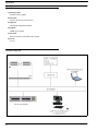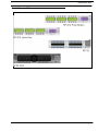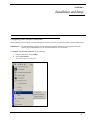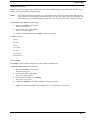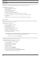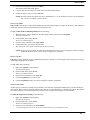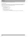
1
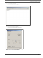
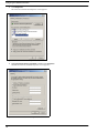
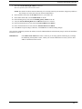
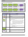
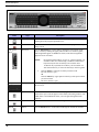
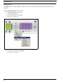
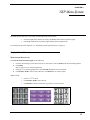
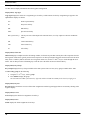
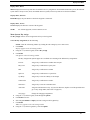
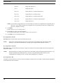
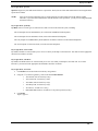
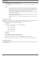
VoIP
Virtual
Keypanel
User Manual
up to and including version 1.2.0
9350-7797-000 Rev C
July/2010
PROPRIETARY NOTICE
SHIPPING TO THE MANUFACTURER
The product information and design disclosed herein were originated by
and are the property of Bosch Security Systems, Inc. Bosch reserves all
patent, proprietary design, manufacturing, reproduction, use and sales
rights thereto, and to any article disclosed therein, except to the extent
rights are expressly granted to others.
All shipments of product should be made via UPS Ground, prepaid (you
may request from Factory Service a different shipment method). Any
shipment upgrades will be paid by the customer. The equipment should
be shipped in the original packing carton. If the original carton is not
available, use any suitable container that is rigid and of adequate size. If
a substitute container is used, the equipment should be wrapped in paper
and surrounded with at least four (4) inches of excelsior or similar
shock-absorbing material. All shipments must be sent to the following
address and must include the Proof of Purchase for warranty repair.
Upon completion of any repair the equipment will be returned via
United Parcel Service or specified shipper, collect.
COPYRIGHT NOTICE
Copyright 2010 by Bosch Security Systems, Inc. All rights reserved.
Reproduction, in whole or in part, without prior written permission from
Bosch is prohibited.
WARRANTY NOTICE
See the enclosed warranty card for further details.
CUSTOMER SUPPORT
Technical questions should be directed to:
Customer Service Department
Bosch Security Systems, Inc.
12000 Portland Avenue South
Burnsville, MN 55337 USA
Telephone: 877-863-4169
Fax: 800-323-0498
[email protected]
Technical Questions EMEA
Bosch Security Systems Technical Support EMEA
http://www.rtsintercoms.com/contact_main.php
RETURN SHIPPING INSTRUCTIONS
Customer Service Department
Bosch Security Systems, Inc. (Lincoln, NE)
Telephone: 402-467-5321
Fax: 402-467-3279
Factory Service: 800-553-5992
Please include a note in the box which supplies the company name,
address, phone number, a person to contact regarding the repair, the type
and quantity of equipment, a description of the problem and the serial
number(s).
Factory Service Department
Bosch Security Systems, Inc.
8601 East Cornhusker Hwy.
Lincoln, NE 68507 U.S.A.
Attn: Service
Stop!
There are two (2) versions of this software that can be
installed from the installation cd, English and Japanese.
Please follow the installation instructions for the version
you desire.
Table
of
Contents
INTRODUCTION ................................................................................................................................... 5
General Description ............................................................................................................................................. 5
Features ................................................................................................................................................................ 5
Specifications ...................................................................................................................................................... 6
System Diagram .................................................................................................................................................. 6
Virtual Keypanel Skins ........................................................................................................................................ 7
INSTALLATION AND SETUP .............................................................................................................. 9
Configuring Your Network Connection .............................................................................................................. 9
SCREEN DESCRIPTIONS .................................................................................................................. 15
Screen Descriptions ........................................................................................................................................... 15
KP-32 Skin ......................................................................................................................................................................15
KP-812 Lever Key and KP-812 Push Button Skin ........................................................................................................18
KP 32 CLD Skin .............................................................................................................................................................20
Settings Screen ................................................................................................................................................................22
VKP MENU SYSTEM ........................................................................................................................... 25
Display Panel Menu .......................................................................................................................................... 25
Menu System, Menu Access ...........................................................................................................................................25
Menu System, Display ....................................................................................................................................................26
Display Menu, Asgn Type ...........................................................................................................................................26
Display Menu, Chans ON ............................................................................................................................................26
Display Menu, Key Groups .........................................................................................................................................26
Display Menu, Key List ...............................................................................................................................................26
Display Menu, Level 2 .................................................................................................................................................26
Display Menu, Listen ...................................................................................................................................................26
Display Menu, Matrix ..................................................................................................................................................27
Display Menu, Panel ID ...............................................................................................................................................27
Display Menu, Version ................................................................................................................................................27
Menu System, Key Assign ..............................................................................................................................................27
Key Assign Menu, PT-to-PT .......................................................................................................................................28
Key Assign Menu, Party Line ......................................................................................................................................28
Key Assign Menu, IFB ................................................................................................................................................28
Key Assign Menu, Spcl List ........................................................................................................................................29
Key Assign Menu, Sys Relay ......................................................................................................................................29
Key Assign Menu, Camera ISO ..................................................................................................................................29
Key Assign Menu, UPL Resrc .....................................................................................................................................29
Key Assign Menu, Auto Func .....................................................................................................................................29
Key Assign Menu, Setup Page ....................................................................................................................................30
Menu System, Key Option ..............................................................................................................................................30
Key Option Menu, Chime ............................................................................................................................................31
Key Option Menu, Key Groups ...................................................................................................................................31
Key Option Menu, Solo ...............................................................................................................................................32
Menu System, Service ....................................................................................................................................................33
Service Menu, Mic Gain ..............................................................................................................................................33
Service Menu, Reset Cfg .............................................................................................................................................34
Service Menu, Save Cfg ..............................................................................................................................................34
Service Menu, Tone Gen .............................................................................................................................................35
Right-Click Menu ..............................................................................................................................................36
Menu System, Menu Access ...........................................................................................................................................36
File, Reset Cfg .............................................................................................................................................................36
File, Save Cfg ..............................................................................................................................................................36
File, Exit ......................................................................................................................................................................37
Menu System, Display ....................................................................................................................................................37
Menu System, Key Assign ..............................................................................................................................................37
Key Assign Menu, Matrix ...........................................................................................................................................38
Key Assign Menu, Pt-to-Pt ..........................................................................................................................................38
Key Assign Menu, Party Line .....................................................................................................................................38
Key Assign Menu, IFB ................................................................................................................................................38
Key Assign Menu, Spcl List ........................................................................................................................................38
Key Assign Menu, Sys Relay ......................................................................................................................................38
Key Assign Menu, Camera ISO ..................................................................................................................................39
Key Assign Menu, UPL Rsrc ......................................................................................................................................39
Key Assign Menu, Auto Func .....................................................................................................................................39
Key Assign Menu, Setup Page ....................................................................................................................................40
Menu System, Key Options ............................................................................................................................................40
Key Option Menu, Chime ............................................................................................................................................40
Key Option Menu, Key Groups ...................................................................................................................................41
Key Option Menu, Solo ...............................................................................................................................................42
Menu System, Service ....................................................................................................................................................43
Service, Settings ..........................................................................................................................................................43
Service, Mic Gain ........................................................................................................................................................44
Service, Tone Gen .......................................................................................................................................................44
Service, Copy CWW ...................................................................................................................................................45
Service, Copy Key .......................................................................................................................................................45
Service, Latch Enable ..................................................................................................................................................45
Service, Flash Timeout ................................................................................................................................................46
VKP MENU SYSTEM QUICK REFERENCE .................................................................................... 47
CHAPTER 1
Introduction
General Description
The RTS VKP (Virtual Keypanel) is a Windows-based application that allows any user to have a fully functioning RTS Matrix
Intercom User Station on their PC.
VKP connects via the PC’s Ethernet connection to any path that can support standard IP protocols, including LAN, WAN, and
VPN.
The VKP application is compatible with any RTS Matrix Intercom equipped with the RVON interface. The VKP brings a new
level of enterprise-wide and remote access to your RTS Matrix Intercom System.
Features
VoIP:
Using the same Voice Over IP technology as the RVON cards, the VoIP Virtual Keypanel is
compatible with any RTS Matrix Intercom System equipped with the RVON interfaces.
GUI Interface Skins:
The RTS Virtual Keypanel has four (4) standard interface skins (KP-32, KP-32 CLD, KP-812
Lever Key, and KP-812 Push Button styles). Other skins can be easily created to fit the needs of
individual environment giving a highly application specific configuration option. Contact Bosch
for special requirements.
Convenience:
With the VKP running under Windows, no special dedicated hardware is required. The same PC
that runs your general purpose applications, such as spreadsheets, word processors, and AZedit can
simultaneously function with a matrix keypanel.
Worldwide Connections: Remote communications using the VKP and a compatible computer. RTS Matrix communications
can be accessed from anywhere in the world that an IP compliant LAN connection can be made.
Installation:
Insert the USB Security Dongle, choose the English or Japanese version, install the software,
connect to the LAN, done.
5
Specifications
Specifications
Operating System:
Windows 2000 or higher
Sound Card:
Must be detected as an audio device
Peripherals:
Microphone and Speaker/Headset
Hard Drive:
20MB space required
Connections:
Ethernet connection and USB security dongle
Protocols:
G.711μ
System Diagram
FIGURE 1.
6
VKP System Diagram
Virtual Keypanel Skins
Virtual Keypanel Skins
FIGURE 2.
Virtual Keypanel Skins
7
Virtual Keypanel Skins
8
CHAPTER 2
Installation and Setup
Configuring Your Network Connection
Before installing VKP on your PC, you must configure the network connection so it functions properly with the VKP software.
IMPORTANT: The VKP application supports static IP Addressing. Dynamic Addressing is not supported at this time.
Contact your IT Administrator to verify the static IP Address for your machine.
To configure your network connection, do the following:
1.
From the Start Menu, select Settings.
2.
Select Control Panel.
The Control Panel screen appears.
Figure 1. Start
Menu
9
Configuring Your Network Connection
Figure 2. Control
10
Panel Window
Configuring Your Network Connection
3.
Select Network Connections.
The Network Connections screen appears.
Figure 3. Network
4.
Connections
Double-click Local Area Connection.
The Local Area Connection Status screen appears.
Figure 4. Local
Area Connection Status Window
11
Configuring Your Network Connection
5.
Click Properties.
The Local Area Connection Properties screen appears.
Figure 5. Local
6.
Area Connection Properties Window
Highlight Internet Protocol (TCP/IP), and then click Properties.
The Internet Protocol (TCP/IP) Properties screen appears.
Figure 6. Internet
12
Protocol (TCP/IP) Properties Window
Configuring Your Network Connection
7.
Select the Use the following IP Address: check box.
The lower portion of the screen becomes active.
NOTE: This check box allows Static IP Addressing. If it is already checked, your IP, subnet, and gateway addresses
may already exist. Verify this with your Network Administrator.
8.
In the IP address field, enter the IP address of the PC you intend to use.
9.
In the Subnet mask field, enter the Subnet mask for the PC.
10.
In the Default gateway field, enter the Default gateway address of the PC.
11.
Verify the Use the following DNS server addresses check box is selected.
12.
In the Preferred DNS server field, enter the Preferred DNS server address.
13.
In the Alternate DNS server field, enter the Alternate DNS server address.
14.
Click OK to accept the changes. Otherwise, click Cancel to exit without making changes.
Once you have configured your Static IP Address, insert the VKP Installation CD and Security dongle. Follow the installation
instructions on the cd.
IMPORTANT:
If the Obtain an IP Address check box is selected, you are using dynamic addressing. If you change
the Addressing from dynamic to static, contact your network administrator to ensure your new static
address is identified on the network.
13
Configuring Your Network Connection
14
CHAPTER 3
Screen Descriptions
Screen Descriptions
The VoIP Virtual Keypanel gives you the ability to customize the application skin. A skin is an element of a GUI (graphical
user interface) that can be changed to alter the look of an application without affecting the functionality of the program. The
VKP currently has four (4) different skins that can be used.
The different skins are:
•
•
•
•
KP-32
KP-32 CLD
KP-812 Lever Key
KP-812 Push Button
KP-32 Skin
Figure 7. KP-32
Field
Skin
Type
Description
Minimize
button
Use the Minimize button to hide a window currently being viewed without
shutting down the program responsible for it.
Exit
button
Use the Exit button to shut the window or terminate the program currently
being viewed.
15
Screen Descriptions
Field
Talk/Listen
Keysa
Type
lever keys
Description
Use the Talk/Listen key to either talk by clicking the lower portion of the
lever, or listen by clicking the upper portion of the lever. On the keypanel,
Talk assignments appear in UPPER case letters, while listen assignments
appear in lower case letters.
NOTE:
1.
By using the Function Keys (F1, F2, etc.) on the keyboard, you
can talk to other users. When using a standard 12-function key
keyboard, only the first 12 talk keys are accessible. On a
16-function key keyboard, all 16 talk keys are accessible. Use
ALT+the function key to access the listen keys on the keypanel.
Click the Talk key of the port to which you want to talk.
The talk channel is open.
OR
Click the Listen key (upper portion of the key) of the port to which
you want to listen.
The listen channel is open.
Display Panel
display
Use the Display Panel to display the different ports associated with each of
the lever keys.
MENU
button
Use the MENU button to activate the underlying VKP menu structure. When
selected, the top-level menu appears in the CWW (call waiting window). The
FWD, BACK, and PGM buttons allow you to navigate through the menu
structure.
FWD
button
Use the FWD button to scroll forward through the VKP menu structure.
BACK
button
Use the BACK button to scroll backward through the VKP menu structure.
MIC MUTE
button
Use the MIC MUTE button to mute the microphone output audio.
To enable Mic Mute, do the following:
Click MIC MUTE.
Mic Mute is enabled. The MIC MUTE button is depressed.
To disable Mic Mute, do the following:
>
>
16
Click MIC MUTE.
Mic Mute is disabled. The MIC MUTE button is not depressed.
CLR
button
Use the CLR button to clear and close the VKP menu structure.
PGM
button
Use the PGM button to accept the menu selection and move you further into
the menu structure.
Number 1-9
button(s)
Use the Number Pad to enter in port alphas.
Screen Descriptions
Field
Volume Adjust
Type
slider
Description
Use the Volume Adjust slider to adjust the keypanel volume level.
To adjust the volume, do the following:
>
NOTE:
Mic Gain
slider
Drag the Volume Adjust slider right to increase the volume or left
to decrease the volume.
The VKP application recalls the last run setting for the volume
every time the application is restarted.
Use the Mic Gain slider to adjust the mic gain. You can also adjust mic gain
through the service menu (see, “Service, Mic Gain” on page 44).
NOTE:
The VKP application recalls the last run setting for Mic Gain
every time the application is restarted.
a. In the Japanese version of the software, the talk LED is Red, while the listen LED is Green. Also, when a user is talking with
someone else an “In-Use” LED lights Green to let other callers know the user is talking to someone else. For example, when
User A calls User B, User C sees Users A and B are talking because the talk LEDs on User C’s keypanel are lit Green.
17
Screen Descriptions
KP-812 Lever Key and KP-812 Push Button Skin
Figure 8. KP-812
Field
Lever Key and Push Button Skin
Type
Description
Minimize
button
Use the Minimize button to hide a window currently being viewed without
shutting down the program responsible for it.
Exit
button
Use the Exit button to shut the window or terminate the program currently
being viewed.
Talk/Listen
Keysa
lever keys
Use the Talk/Listen key to either talk by clicking the lower portion of the
lever, or listen by clicking the upper portion of the lever. On the keypanel,
Talk assignments appear in UPPER case letters, while listen assignments
appear in lower case letters.
NOTE:
1.
18
By using the Function Keys (F1, F2, etc.) on the keyboard, you
can talk to other users. When using a standard 12-function key
keyboard, only the first 12 talk keys are accessible. On a
16-function key keyboard, all 16 talk keys are accessible. Use
ALT+the function key to access the listen keys on the keypanel.
Click the Talk key of the port to which you want to talk.
The talk channel is open.
OR
Click the Listen key (upper portion of the key) of the port to which
you want to listen.
The listen channel is open.
Display Panel
display
Use the Display Panel to display the different ports associated with each of
the lever keys.
MENU
button
Use the MENU button to activate the underlying VKP menu structure. When
selected, the top-level menu appears in the CWW (call waiting window). The
FWD, BACK, and PGM buttons allow you to navigate through the menu
structure.
Screen Descriptions
Field
Type
Description
FWD
button
Use the FWD button to scroll forward through the VKP menu structure.
BACK
button
Use the BACK button to scroll backward through the VKP menu structure.
MIC MUTE
button
Use the MIC MUTE button to mute the microphone output audio.
To enable Mic Mute, do the following:
Click MIC MUTE.
Mic Mute is enabled. The MIC MUTE button is depressed.
To disable Mic Mute, do the following:
>
>
Click MIC MUTE.
Mic Mute is disabled. The MIC MUTE button is not depressed.
CLR
button
Use the CLR button to clear and close the VKP menu structure.
PGM
button
Use the PGM button to accept the menu selection and move you further into
the menu structure.
Number 1-9
button(s)
Use the Number Pad to enter in port alphas.
Pages 1 - 4
LED display
lights
The 1 - 4 LED lights display which key assignment page is being shown.
Volume Adjust
slider
Use the Volume Adjust slider to adjust the keypanel volume level.
To adjust the volume, do the following:
>
NOTE:
Mic Gain
slider
Drag the Volume Adjust slider right to increase the volume or left
to decrease the volume.
The VKP application recalls the last run setting for the volume
every time the application is restarted.
Use the Mic Gain slider to adjust the mic gain. You can also adjust mic gain
through the service menu (see, “Service, Mic Gain” on page 44).
NOTE:
The VKP application recalls the last run setting for Mic Gain
every time the application is restarted.
a. In the Japanese version of the software, the talk LED is Red, while the listen LED is Green. Also, when a user is talking with
someone else an “In-Use” LED lights Green to let other callers know the user is talking to someone else. For example, when
User A calls User B, User C sees Users A and B are talking because the talk LEDs on User C’s keypanel are lit Green.
19
Screen Descriptions
KP 32 CLD Skin
Figure 9. KP
32 CLD Skin
Field
Type
Description
Minimize
button
Use the Minimize button to hide a window currently being viewed without
shutting down the program responsible for it.
Exit
button
Use the Exit button to shut the window or terminate the program currently
being viewed.
Talk/Listen
Keysa
lever keys
Use the Talk/Listen key to either talk by clicking the lower portion of the
lever, or listen by clicking the upper portion of the lever. On the keypanel,
Talk assignments appear in UPPER case letters, while listen assignments
appear in lower case letters.
NOTE:
1.
20
By using the Function Keys (F1, F2, etc.) on the keyboard, you
can talk to other users. When using a standard 12-function key
keyboard, only the first 12 talk keys are accessible. On a
16-function key keyboard, all 16 talk keys are accessible. Use
ALT+the function key to access the listen keys on the keypanel.
Click the Talk key of the port to which you want to talk.
The talk channel is open.
OR
Click the Listen key (upper portion of the key) of the port to which
you want to listen.
The listen channel is open.
Display Panel
display
Use the Display Panel to display the different ports associated with each of
the lever keys.
MENU
button
Use the MENU button to activate the underlying VKP menu structure. When
selected, the top-level menu appears in the CWW (call waiting window). The
FWD, BACK, and PGM buttons allow you to navigate through the menu
structure.
FWD
button
Use the FWD button to scroll forward through the VKP menu structure.
BACK
button
Use the BACK button to scroll backward through the VKP menu structure.
Screen Descriptions
Field
MIC MUTE
Type
button
Description
Use the MIC MUTE button to mute the microphone output audio.
To enable Mic Mute, do the following:
Click MIC MUTE.
Mic Mute is enabled. The MIC MUTE button is depressed.
To disable Mic Mute, do the following:
>
>
Click MIC MUTE.
Mic Mute is disabled. The MIC MUTE button is not depressed.
CLR
button
Use the CLR button to clear and close the VKP menu structure.
PGM
button
Use the PGM button to accept the menu selection and move you further into
the menu structure.
Number 1-9
button(s)
Use the Number Pad to enter in port alphas.
Volume Adjust
slider
Use the Volume Adjust slider to adjust the keypanel volume level.
To adjust the volume, do the following:
>
NOTE:
Mic Gain
slider
Drag the Volume Adjust slider right to increase the volume or left
to decrease the volume.
The VKP application recalls the last run setting for the volume
every time the application is restarted.
Use the Mic Gain slider to adjust the mic gain. You can also adjust mic gain
through the service menu (see, “Service, Mic Gain” on page 44).
NOTE:
The VKP application recalls the last run setting for Mic Gain
every time the application is restarted.
a. In the Japanese version of the software, the talk LED is Red, while the listen LED is Green. Also, when a user is talking with
someone else an “In-Use” LED lights Green to let other callers know the user is talking to someone else. For example, when
User A calls User B, User C sees Users A and B are talking because the talk LEDs on User C’s keypanel are lit Green.
21
Screen Descriptions
Settings Screen
The Settings screen is used to configure connection options, audio settings and incoming call notifications for the Virtual
Keypanel.
To get to the Settings screen, do the following:
1.
Right-click anywhere on the VKP.
The Main Menu appears.
2.
From the Main Menu, select Service.
The Service menu appears.
Figure 10. Service
3.
22
Menu
From the Service Menu, select Settings.
The Settings screen appears.
Screen Descriptions
Figure 11. Settings
Field
Window
Type
Layout
drop down list
Description
Use the Layout drop down list to choose what interface skin users sees when
the Virtual Keypanel is running. There are four (4) different skins available:
KP-32
KP-32 CLD
KP-812 Lever Key
KP-812 Push Button
Server
drop down list
1.
From the Layout drop down list, select KP-32, KP-32 CLD, KP-812
Lever Key, KP-812 Push Button.
2.
Click OK.
The Settings screen closes and the keypanel skin changes to your
choice.
The Server is the port address of the RVON device to which the VKP software
connects.
1.
Local IP
drop down list
From the Server drop down list, select the server to which you want
to connect.
The Local IP is the IP (Internet Protocol) Address of the computer where the
VoIP Virtual Keypanel is installed.
1.
NOTE:
From the Local IP drop down list, select the IP Address you want to
use.
A computer can have more than one IP Address. Separate IP
Addresses are associated with each Ethernet card. Therefore,
multiple Ethernet cards allow for multiple IP Addresses.
Audio Settings
NOTE:
Audio settings are changed in AZedit. For more information, see the AZedit User Manual.
23
Screen Descriptions
Field
Codec
Type
display
Description
Codec displays the codec used to compress the audio for transmittal. There are
two codecs supported by Bosch’s VKP, G.711μ law and G.711A law. The type
of codec dictates the quality of audio you hear and the network bandwidth
used.
NOTE:
If you assign another codec for the VKP from an RVON device
other than G.711μ law or G.711A law, VKP negotiates a G.711
codec.
Frame Size
display
The Frame Size displays how much audio is in an individual packet.
VAD
check box
VAD (voice activity detection) saves network bandwidth by stopping the flow
of audio packets when silence is detected. Select the VAD check box to enable
this feature in VKP.
Incoming Call Notification
24
Bring Keypanel
to Front
check box
When enabled, the application is brought to the front of all other applications
and is made active.
Flash icon
check box
When enabled, the VKP icon flashes when a call is received and the VKP
window is behind other applications. The VKP icon is located in the system
tray.
Pop-up
Notification
check box
When enabled, a pop-up notification appears near the VKP icon (which flashes
orange) in the system tray when a call is received and the VKP window is
located behind other application windows.
Lock Keypanel
Position
check box
When enabled, the keypanel cannot be moved from its position on the desktop.
OK
button
The OK button accepts the changes and closes the Settings screen.
Cancel
button
The Cancel button clears the changes made and closes the Settings screen.
CHAPTER 4
VKP Menu System
The VKP menu system can be accessed at two different points in the software:
•
•
From the Display Panel Menu (accessed by the MENU button on the keypanel keypad).
From Right-Click Menu (accessed by right-clicking on the keypanel skin).
For a diagram of the menu structures, see “VKP Menu System Quick Reference” on page 47.
Display Panel Menu
Menu System, Menu Access
To access the menu from the keypad, do the following:
1.
Click the call-waiting key in the listen area one or more times to clear all names from the call-waiting window.
2.
Click Menu.
Display appears in the Call Waiting Window.
3.
Using the ↓↓ (9 on the keypad) arrows, scroll forward through the list of menu items.
4.
Click FWD or PGM to enter a menu. Otherwise, click BACK to exit a menu option.
Within a menu,
•
•
•
FIGURE 3.
Click ↓↓ or ↑↑ to scroll.
Click FWD or PGM to select an item
Click BACK to cancel a selection or to go back to a previous menu.
KP-32, KP-812 and KP-32 CLD keypads
25
Display Panel Menu
Menu System, Display
Use this menu to display information about the keypanel configuration.
Display Menu, Asgn Type
Asgn Type displays the talk level 1 assignment types for all keys. Abbreviations for the key assignment types appear in the
alphanumeric displays as follows:
P-P
Point-to-point talk key
PL
Party Line talk key
IFB
IFB talk key
SPCL
Special List talk key
RLY (system relay)
This key activates a GP output at the intercom frame, or a relay output at a UIO-256 or FR9528
frame
ISO
Camera ISO talk key
UPL
UPL resource key
AC
All Call key
Display Menu, Chans ON
Chans ON displays an alpha list in the call waiting window, of all intercom ports that currently have talk crosspoints closed to
this keypanel. Chans ON is typically used to locate an open mic or other open audio sources that need to be shut off. The most
likely cause is a talk key that has been left on at a keypanel. In this case, use the ↓↓ and ↑↑ keys to scroll through the list of
names. You can then press the Call Waiting key to ask the user at the other end to turn off their talk key.
Display Menu, Key Groups
Key Groups displays the Key Groups available in the VKP system. There are four (4) key groups available in the VKP.
To select a key group, do the following:
1.
Using the ↓↓ or ↑↑ keys, select a group.
2.
Press PGM to display the group.
The talk and listen LEDs of the master key light red, and the talk and listen LEDs for the slave keys light green.
Display Menu, Key List
Key List displays and allows access to all the other assignments on other keypanel pages that are not currently showing in the
keypanel display.
Display Menu, Level 2
Level 2 displays the talk level 2 assignments for all keys.
Display Menu, Listen
Listen displays the listen assignments for all keys.
26
Display Panel Menu
Display Menu, Matrix
Matrix displays the intercom system name for all talk level 1 key assignments. In non-trunked intercom systems, the intercom
system name is always LOCL (local). In trunked intercom systems, intercom systems are created in TrunkEdit.
Display Menu, Panel ID
Panel ID displays the port number to which the keypanel is connected.
Display Menu, Version
Version displays the firmware version of the keypanel.
NOTE:
For software upgrades, contact customer service.
Menu System, Key Assign
The Key Assign menu is used to assign intercom keys to the keypanel.
To use the key assign menu, do the following:
NOTE: Clear the call waiting window by clicking the call waiting key one or more times.
1.
Click Menu.
Display appears in the call waiting window.
2.
Using the ↓↓ (9 on the keypad), scroll to Key Assign.
3.
Click PGM.
P-P appears in the call waiting window.
The Key Assign menu options appear as a scrollable list consisting of the different key assignments:
Pt-to-Pt:
Assign a key to talk/listen to another intercom port.
Party Line:
Assign a key to talk/listen to a party line.
IFB:
Assign a key to talk/listen to an IFB.
Spcl List:
Assign a key to talk/listen to a special list.
Sys Relay:
Assign a key to activate a Relay or GP Output.
Camera ISO:
Assign a key to talk/listen to an ISO.
UPL Resrc:
Assign a key to activate a UPL Resource.
Auto Func:
Assign an auto function to a key. (If you select this item, skip the rest of this procedure and
go to “Key Assign Menu, Auto Func” on page 29.)
Setup Page:
Change the setup page assignments.
4.
Using the ↓↓ (9 on the keypad), scroll through the options.
5.
Click PGM to select it.
6.
Select the port number or alpha you want to assign to the keypanel key.
7.
Click PGM.
Talk Level 1 appears in the call waiting window.
8.
Using the ↓↓ (9 on the keypad) key, scroll the options.
27
Display Panel Menu
Available options for this field are:
Talk Lvl 1
Assigns only talk level 1
Listen
Assigns only listen
Talk + AF
Assigns talk level 1, with auto-follow listen
Talk + AL
Assigns talk level 1, with auto-listen
Talk + AM
Assigns talk level 1, with auto-mute listen
Talk + AR
Assigns talk level 1, with auto-reciprocal listen
Talk + Lvl 2
Assigns talk level 2
NOTE: If you attempt to assign a talk level 2 to a key and there is no talk level 1 assignment, the assignment goes on
talk level 1. If you change the talk level 1 assignment for a key that also has a talk level 2 assignment, the
talk level 2 assignment is erased.
9.
Click PGM.
Tap Key appears in the call waiting window.
10.
Click the key you want to give the assignment.
The assignment alpha appears in the display window of the keypanel key.
11.
Click CLR to exit out of the menu structure.
Key Assign Menu, PT-to-PT
PT-to-PT assigns a key that talks or listens to another intercom port.
NOTE:
Some point-to-point destinations may be non-keypanel devices that cannot activate talk and listen paths.
Therefore, if you want full communication, you may need to assign both talk and listen on the key.
Key Assign Menu, Party Line
Party Line assigns a key that talks and/or listens to a party line. This has no effect until members have been assigned to the
party line in AZedit.
NOTE:
Party line members are usually non-keypanel devices that cannot activate talk and listen paths. Therefore, if you
want full communication with the party line, you need to assign both talk and listen on the key. If all
communications is normally be 2-way, you may want to assign the key as Talk+AL.
Key Assign Menu, IFB
All IFBs are restricted and you see Not Avail when you attempt to select this item. To see IFBs, you must check the appropriate
scroll enable check boxes in AZedit.
28
Display Panel Menu
Key Assign Menu, Spcl List
Spcl List assigns a key that talks and/or listens to a special list. The key has no effect until members have been assigned to the
special list in AZedit.
NOTE:
Some or all special list members may be non-keypanel devices that cannot activate talk and listen paths.
Therefore, if you want full communication with all members of the special list, you may need to assign both talk
and listen on the key.
Key Assign Menu, Sys Relay
Sys Relay refers to several types of control devices that can exist in the intercom system, including:
The 8 GP outputs from an ADAM frame (J11 on the XCP-ADAM-MC breakout panel)
The 8 GP outputs from an ADAM CS frame (J903 on the ADAM CS backpanel)
The relay outputs of an FR9528 Relay Frame (RELAY OUTPUTS connector on the FR9528 backpanel)
The 16 GP outputs of a UIO-256 frame (J5 on the UIO-256 backpanel).
Key Assign Menu, Camera ISO
By default, all ISOs are restricted and you see Not Avail when you attempt to select this item. You must select the appropriate
check box in AZedit to see ISOs.
Key Assign Menu, UPL Resrc
By default, all UPL Resources are restricted and you see Not Avail when you attempt to select this item. To see UPL
Resources, you must select the appropriate Scroll Enable check box in AZedit.
Key Assign Menu, Auto Func
1.
Click PGM to select auto functions in the Key Assign menu.
2.
Using the ↓↓ (9 on the keypad) key, scroll to the desired auto function:
•
•
•
•
•
•
3.
Auto Follow (AF, for listen keys only)
Auto Listen (AL, for listen keys only)
Auto Mute (AM, for listen keys only)
Auto Recip (AR, for listen keys only)
All Call (AC, for talk level 1 only)
DIM (DIM Table function, for talk level 2 on point-to-point keys only)
Click PGM.
Tap Key appears.
29
Display Panel Menu
4.
Click a keypanel key to assign the selected auto function.
Click the upper portion of the key to assign auto functions except All Call or DIM. Click the lower portion of the key
for All Call and DIM.
NOTE:
•
If the assignment is successful, the abbreviation for the auto function appears in the alphanumeric
display for that key. However, if you try to assign an auto function to a key that already has that auto
function assigned, the assignment is ignored. The assignment is also ignored if scroll enable for auto
functions is not selected in AZedit, or if the key you are trying to assign is restricted.
•
You can click CLR to exit and return to normal operation, or click BACK to return to the auto function
menu and make more assignments.
•
Trunked intercom systems: Do not select a matrix before assigning auto functions. All auto functions
are assigned using the local Matrix menu.
•
You do not need to run Save Cfg to store auto function assignments. These are stored in the intercom
system.
Key Assign Menu, Setup Page
Setup Page is used to change the setup page assignments on the KP-32, KP-812, KP-32 CLD, EKP-32, and EKP-812. One
setup page is used for the top row of keys, and another setup page is used for the bottom row of keys.
1.
Click PGM to select Setup Page in the Key Assign menu.
Page 1 displays.
2.
Using the ↓↓ (9 on the keypad) key, select any of the following pages:
Page 1: Assign setup page 1
Page 2: Assign setup page 2
Page 3: Assign setup page 3
Page 4: Assign setup page 4
Clear Page: Clear a page
3.
Click PGM.
Tap Keys appears.
4.
Click any key in the row where you want to assign the setup.
The key assignments for that page should appear in the displays.
5.
Using the ↓↓ (9 on the keypad) key, scroll to a different setup page. Otherwise, click CLR to exit.
NOTE: You do not need to run Save Cfg to store changes to the setup pages. These are stored in the intercom.
Menu System, Key Option
The Key Option menu is used to set announcement chimes for incoming calls, to assign key groups to keypanel keys, and to
assign the solo option to keys.
30
Display Panel Menu
Key Option Menu, Chime
The Chime menu is used to add a chime tone to any key for an incoming call announcement. The chime tone activates for five
(5) seconds after a call is received.
To add a chime tone, do the following:
1.
On the keypanel, click MENU.
Display appears in the call waiting window.
2.
Using the ↓↓ (9 on the keypad) key, scroll to Key Option.
3.
Click PGM.
Chime appears in the call waiting window.
4.
Click PGM.
Tap Key appears in the call waiting window.
5.
Click the keypanel key you want to assign the chime.
6.
Run Service, Save Cfg to store the chime setting.
NOTE: The chime option continues on a key even if you change the key assignment.
To remove the chime tone from a key, repeat the procedure to add a chime, but click any keys where the LEDs are lit red to
turn them off. Run Save Cfg to store the changes.
Key Option Menu, Key Groups
Key Groups are groups of users associated to each other through a common key, called a master key. A key group can be
created so that when one (1) key (the master key) is activated, all keys in the group are activated. Up to four (4) key groups can
be configured.
To create a key group, do the following:
1.
On the keypanel, click MENU.
Display appears in the call waiting window.
2.
Using the ↓↓ (9 on the keypad) key, scroll to Key Option.
3.
Click PGM.
Chime appears in the call waiting window.
4.
Using the ↓↓ (9 on the keypad) key, scroll to Key Groups.
5.
Click PGM.
Tap Master appears in the call waiting window. The master key is the key you click to activate the group.
6.
Click the keypanel key you want as the master.
Both the LEDs next to the key lights red and “tap slaves” appears in the call waiting window. Slave keys are the keys
that activate along with the master.
7.
Click one (1) or more keys to select slaves for that group.
Both LEDs lights green next to each key selected. You can click a key again to remove it from the group.
8.
Click CLR to exit.
Activating the master key now causes it and all slave keys to activate. The LEDs for each key activates according to
the current key assignment for that key.
9.
Run Service, Save Cfg to store the key group setting.
NOTE: Key group settings continue on keys even if the key assignments are changed.
To clear a key group, do the following:
1.
On the keypanel, click MENU.
Display appears in the call waiting window.
2.
Using the ↓↓ (9 on the keypad) key, scroll to Key Option.
31
Display Panel Menu
3.
Click PGM.
Chime appears in the call waiting window.
4.
Using the ↓↓ (9 on the keypad) key, scroll to Key Groups.
5.
Click PGM.
Tap Master appears in the call waiting window.
6.
Click the current Master Key.
The LEDs next to the key remain lit and “tap slaves” appears in the call waiting window.
7.
Click all the keys where the LEDs are lit green.
This turns the LEDs off.
8.
Click CLR to exit.
The key group is cleared.
9.
Run Service, Save Cfg to store the key group setting.
Key Option Menu, Solo
Use the Solo option to put current, active users on hold and talk to a single user. For example, you may be in a Key Group and
want to ask a question to a certain individual. You can use the solo option to put the key group on hold.
To use the solo option, do the following:
1.
On the keypanel, click MENU.
Display appears in the call waiting window.
2.
Using the ↓↓ (9 on the keypad) key, scroll to Key Option.
3.
Click PGM.
Chime appears in the call waiting window.
4.
Using the ↓↓ (9 on the keypad) key, scroll to Solo.
5.
Click PGM.
Tap Key appears in the call waiting window.
6.
Click the keypanel key you want to assign solo.
Both the LEDs next to the key lights red to confirm the assignment. Click the key again if you want to remove the
assignment.
7.
Click CLR to exit.
Activating the solo key causes all other activated keys to turn off. The keys turn back on when you turn the solo key
off.
8.
Run Service, Save Cfg to store the Solo settings.
NOTE: The Solo option continues on a key even if you change the key assignment.
32
Display Panel Menu
To remove the solo key option, do the following:
1.
2.
On the keypanel, click MENU.
Display appears in the call waiting window.
Using the ↓↓ (9 on the keypad) key, scroll to Key Option.
3.
Click PGM.
Chime appears in the call waiting window.
4.
Using the ↓↓ (9 on the keypad) key, scroll to Solo.
5.
Click PGM.
Both LEDs next to the solo key light.
6.
Click the solo key.
The solo option is cleared from the key.
7.
Run Service, Save Cfg to store the Solo setting.
Menu System, Service
Use the Service Menu to access many of the options within the VKP, such as Mic Gain, Ton Gen, Copy CWW, Copy Key,
Latch Enable, and Flash Timeout.
NOTE:
When using the Display Panel Menu structure, Save Cfg and Reset Cfg are in the Service Menu. On the Main
Menu, Save Cfg and Reset Cfg are in the File Menu. Also, Copy CWW, Copy Key, Latch Enable, and Flash
Timeout are only available through the Main Menu. You cannot use them from the display menu.
Service Menu, Mic Gain
Mic Gain is the level of audio being sent through the microphone. You can set the gain level anywhere from 0% to 100%.
To set the Mic Gain, do the following:
1.
On the keypanel, click MENU.
Display appears in the call waiting window.
2.
Using the ↓↓ (9 on the keypad) key, scroll to Service.
3.
Click PGM.
Mic Gain appears in the call waiting window.
4.
Click PGM.
The gain percentage appears in the call waiting window.
5.
Using the ↓↓ or ↑↑ keys, decrease or increase the mic gain.
6.
Click CLR to exit.
NOTE: You can also adjust the Mic Gain using the slider on keypanel.
33
Display Panel Menu
Service Menu, Reset Cfg
Use Reset Cfg to restore all custom settings to the application defaults. The defaults for Reset Cfg are as follows:
Speaker Volume: 25%
Mic Gain: 60%
Latch Enable: on
Flash Timeout: on
Local IP: Default (cleared so default is used)
All key options (for each key) are removed
Solo = off
Chime = off
Groups are cleared
To reset the configuration, do the following:
1.
On the keypanel, click MENU.
Display appears in the call waiting window.
2.
Using the ↓↓ (9 on the keypad) key, scroll to Service.
3.
Click PGM.
Mic Gain appears in the call waiting window.
4.
Using the ↓↓ (9 on the keypad) key, scroll to Reset Cfg.
5.
Click PGM.
The system restores all the application defaults.
Service Menu, Save Cfg
Use Save Cfg to save custom settings you have made in the Key Option, Key Assign, or Service menus. These settings are
stored in non-volatile memory. This ensures protection of your settings when you exit the program.
To save the configuration, do the following:
34
1.
On the keypanel, click MENU.
Display appears in the call waiting window.
2.
Using the ↓↓ (9 on the keypad) key, scroll to Service.
3.
Click PGM.
Mic Gain appears in the call waiting window.
4.
Using the ↓↓ (9 on the keypad) key, scroll to Save Cfg.
5.
Click PGM.
The system saves the configuration settings.
Display Panel Menu
Service Menu, Tone Gen
Tone Gen (Tone Generator) gives you the ability to check the audio path from the keypanel to the matrix and back. You can
change the default tone you hear with any .wav file you want. To change the .wav file, see “To change the default tone
generation file, do the following:” on page 44.
To use Tone Gen, do the following:
1.
On the keypanel, click MENU.
Display appears in the call waiting window.
2.
Using the ↓↓ (9 on the keypad) key, scroll to Service.
3.
Click PGM.
Mic Gain appears in the call waiting window.
4.
Using the ↓↓ (9 on the keypad) key, scroll to Tone Gen.
5.
Click PGM.
TONE ON appears. This indicates the Tone Gen is active.
NOTE: When Tone Gen is enabled, the keypanel continues to send audio even when the key is not selected. This is
important because it uses network bandwidth if is not disabled after testing.
6.
Click the key you wish to check for an audio path.
A tone sounds at the destination keypanel.
35
Right-Click Menu
Right-Click Menu
The Right-Click Menu is a right-click accessible menu structure for the VoIP Virtual Keypanel. It is similar to the display
panel menu, yet not exactly the same.
The Right-Click Menu contains a File menu item that is not present in the Display Panel Menu. It contains the Reset Cfg, Save
Cfg, and an Exit item.
The Right-Click Menu also contains Settings, Copy CWW, Latch Enable, and Flash Timeout items in the Service menu that
are not present in the Display Panel menu.
Menu System, Menu Access
To access the application menu from the right-click menu, do the following:
1.
Right-click anywhere on the keypanel.
A popup menu appears.
2.
Select the menu item you want to access.
The top level popup menu has the following items. For a complete navigation menu, see “VKP Menu System Quick
Reference” on page 47.
File
Display
Key Assign
Key Options
Service
File, Reset Cfg
Reset Cfg is used to restore all custom settings to the application defaults. See the system defaults on page 34.
To perform Reset Cfg, do the following:
1.
Right-click on the keypanel.
A popup menu appears.
2.
From the popup menu, select File.
The File submenu appears.
3.
From the File submenu, select Reset Cfg.
The system restores the application defaults.
File, Save Cfg
Save Cfg is used to save custom settings that have been made in the Key Option, Key Assign, or Service menus. These
settings are saved on the Matrix in non-volatile memory to ensure your settings are preserved when you exit the application.
To perform Save Cfg, do the following:
36
1.
Right-click on the keypanel.
A popup menu appears.
2.
From the popup menu, select File.
The File submenu appears.
3.
From the File submenu, select Save Cfg.
The system saves the changes.
Right-Click Menu
File, Exit
Exit is used to close the VKP application.
To exit out of the VKP application, do the following:
1.
Right-click on the keypanel.
A popup menu appears.
2.
From the popup menu, select File.
The File submenu appears.
3.
From the File submenu, select Exit.
The VKP application closes.
Menu System, Display
Display menu is used to view information about the keypanel configuration.
Available options are:
•
•
•
•
•
•
•
•
•
Assign Type
Chans ON
Key Groups
Key List
Level 2
Listen
Matrix
Panel ID
Version
To access the Display menu, do the following:
1.
Right-click on the keypanel.
A popup menu appears.
2.
From the popup menu, select Display.
The Display submenu appears.
3.
From the Display submenu, select the item you want to view.
Menu System, Key Assign
Use the Key Assign menu to assign intercom keys to the keypanel, to adjust listen levels for point-to-point and party line keys,
and to assign setup pages.
Available options are:
Pt-to-Pt
Party Line
IFB
Spcl List
Sys Relay
Camera ISO
UPL Rsrc
37
Right-Click Menu
Auto Func
Setup Page
To access the key assign menu, do the following:
1.
Right-click anywhere on the keypanel.
The Main menu appears.
2.
From the Main menu, select Key Assign.
The Key Assign submenu appears.
3.
From the Key Assign submenu, select the option you want to use.
An Alpha appears in the call waiting window.
Key Assign Menu, Matrix
Matrix appears only for trunked intercom systems. You must select a remote intercom matrix before assigning intercom keys
to destinations in that matrix. You do not need to select a matrix to assign keys to destinations in your own matrix. You also do
not need to select a matrix when assigning an auto function to a key.
Key Assign Menu, Pt-to-Pt
Pt-to-Pt is used to assign a key that talks or listens to another intercom port. Note, some pt-to-pt destinations may be nonkeypanel devices that cannot activate talk and listen paths. Therefore, if you want full communication, you may need to assign
both talk an listen on the key.
Key Assign Menu, Party Line
Party Line is used to assign a key that talks and/or listens to a party line. This has no effect until members have been assigned
to the party line in AZedit. Note, party line members are usually non-keypanel devices that cannot activate talk and listen
paths. Therefore, if you want full communication with the party line, you must assign both talk and listen on the key. If all
communications are normally 2-way, you may want to assign the key as Talk+AL.
Key Assign Menu, IFB
By default, all IFBs are restricted and you see Not Avail when you attempt to select this item. To see IFBs, you must check the
appropriate Scroll Enable check box in AZedit.
Key Assign Menu, Spcl List
Spcl List is used to assign a key that talks and/or listens to a special list. The key has no effect until members have been
assigned to the special list in AZedit. Note, some or all special list members may be non-keypanel devices that cannot activate
talk and listen paths. Therefore, if you want full communication with all members of the special list, you may need to assign
both talk and listen on the key.
Key Assign Menu, Sys Relay
System Relay refers to any of several types on control devices that can exist in the intercom system, including:
The 8 GP outputs from an ADAM frame (J11 on the XCP-ADAM-MC breakout panel)
The 8 GP outputs from an ADAM CS frame (J903 on the ADAM CS backpanel)
The relay outputs of an FR9528 Relay Frame (RELAY OUTPUTS connector on the FR9528 backpanel)
The 16 GP outputs of a UIO-256 frame (J5 on the UIO-256 backpanel).
38
Right-Click Menu
Key Assign Menu, Camera ISO
By default, all ISOs are restricted and you see Not Avail when you attempt to select this item. To see ISOs, you must select the
appropriate check box in AZedit.
Key Assign Menu, UPL Rsrc
By default, all UPL Resources are restricted and you see Not Avail when you attempt to select this item. To see UPL
Resources, you must select the appropriate Scroll Enable check box in AZedit.
Key Assign Menu, Auto Func
To Assign the auto function, do the following:
1.
Right-click anywhere on the keypanel.
The Main menu appears.
2.
From the Main menu, select Key Assign.
The Key Assign submenu appears.
3.
From the Key Assign submenu, select the option you want to use.
Auto Follow (AF, for listen keys only)
Auto Listen (AL, for listen keys only)
Auto Mute (AM, for listen keys only)
Auto Recip (AR, for listen keys only)
All Call (AC, for talk level 1 only)
DIM (DIM Table function, for talk level 2 on point-to-point keys only)
NOTE:
•
If the assignment is successful, the abbreviation for the auto function appears in the alphanumeric
display for that key. However, if you try to assign an auto function to a key that already has that auto
function assigned, the assignment is ignored. The assignment is also ignored if scroll enable for auto
functions is not selected in AZedit, or if the key you are trying to assign is restricted.
•
You can click CLR to exit and return to normal operation, or click BACK to return to the auto function
menu and make more assignments.
•
Trunked intercom systems: Do not select a matrix before assigning auto functions. All auto functions
are assigned using the local Matrix menu.
•
You do not need to run Save Cfg to store auto function assignments. These are stored in the intercom
system.
39
Right-Click Menu
Key Assign Menu, Setup Page
Setup Page is used to change the setup page assignments on the KP-32, KP-812, KP-32 CLD, EKP-32, and EKP-812. One
setup page is used for the top row of keys, and another setup page is used for the bottom row of keys.
To set up a page, do the following:
1.
Right-click anywhere on the keypanel.
The Main menu appears.
2.
From the Main menu, select Key Assign.
The Key Assign submenu appears.
3.
From the Key Assign submenu, select any of the following:
Page 1: Assign setup page 1
Page 2: Assign setup page 2
Page 3: Assign setup page 3
Page 4: Assign setup page 4
Clear Page: Clear a page
NOTE: You do not need to run Save Cfg to store changes to the setup pages. These are stored in the intercom.
Menu System, Key Options
Key Options is used to set announcement chimes for incoming calls, to assign key groups to keypanel keys, and to assign the
solo option to keys.
Key Option Menu, Chime
Chime is used to add a chime tone to any key for an incoming call announcement. The chime tone activates for five (5)
seconds after a call is received.
To add a chime tone, do the following:
1.
Right-click anywhere on the keypanel.
The Main menu appears.
2.
From the Main menu, select Key Option.
The Key Option submenu appears.
3.
From the Key Option submenu, select Chime.
Tap Key appears.
4.
Click the key where you want to add the Chime tone.
Both red LEDs are lit. The Chime is enabled.
5.
Run File, Save Cfg to save the chime setting.
NOTE: The chime option continues on key even if you change the key assignment. To remove the chime tone from
a key, repeat the procedure to add a chime, but click any keys where the LEDs are lit red to turn them off.
Run File, Save Cfg to store the changes.
40
Right-Click Menu
Key Option Menu, Key Groups
Key Groups are groups of users that are associated to each other through a common key, called a master key. A key group can
be created so that when one key (the master key) is activated, all keys in the group activate. Up to four (4) key groups can be
set up.
To create a key group, do the following:
1.
Right-click anywhere on the keypanel.
The Main menu appears.
2.
From the Main menu, select Key Option.
The Key Option submenu appears.
3.
From the Key Option submenu, select Key Groups.
The Key Groups submenu appears.
4.
From the Key Groups submenu, select the page you want to use.
Tap Master appears in the call waiting window. The master key is the key you click to activate the group.
5.
Click the keypanel key you want to use as the master.
Both LEDs next to the key light red and “tap slaves” appears in the call waiting window. Slave keys are the keys that
activate along with the master.
6.
Click one or more keys to select slaves for that group.
Both LEDs light green next to each key selected. You can click a key again to remove it from the group.
7.
Click CLR to exit.
Activating the master key now causes it and all slave keys to activate. The LEDs for each key activate according to
the current key assignment for that key.
8.
Run Service, Save Cfg to store the key group setting.
NOTE: Key group settings continue on keys even if the key assignments are changed.
To clear a key group, do the following:
1.
Right-click anywhere on the keypanel.
The Main menu appears.
2.
From the Main menu, select Key Option.
The Key Option submenu appears.
3.
From the Key Option submenu, select Key Groups.
The Key Groups submenu appears.
4.
From the Key Groups submenu, select the page you want to use.
Tap Master appears in the call waiting window.
5.
Click the current master key.
All LEDs next to the key remain lit and “tap slaves” appears in the call waiting window.
6.
Click all the keys where the LEDs are lit green.
This turns all the LEDs off.
7.
Click CLR to exit.
The Key Group is cleared.
8.
Run Service, Save Cfg to store the key group setting.
41
Right-Click Menu
Key Option Menu, Solo
Solo is used to put current active users on hold and talk to a single user. For example, you may in a key group and want to ask
a question to an individual user. You can use the solo option to put the group on hold while you talk with the individual.
To use the solo option, do the following:
1.
Right-click anywhere on the keypanel.
The Main menu appears.
2.
From the Main menu, select Key Option.
The Key Option submenu appears.
3.
From the Key Option submenu, select Solo.
Tap Key appears in the call waiting window.
4.
Click the keypanel key to which you want to assign solo.
Both LEDS next to the key light red to confirm the assignment. Click the key again if you want to remove the
assignment.
5.
Click CLR to exit.
Activating the solo key causes all other activated keys to turn off. The keys turn back on when you turn the solo key
off.
6.
Run Service, Save Cfg to store the Solo setting.
NOTE: The Solo option continues on a key even if you change the key assignment.
To remove the solo key option, do the following:
42
1.
Right-click anywhere on the keypanel.
The Main menu appears.
2.
From the Main menu, select Key Option.
The Key Option submenu appears.
3.
From the Key Option submenu, select Solo.
Both LEDs next to the solo key light.
4.
Click the solo key.
The solo key is cleared.
5.
Run Service, Save Cfg to store the Solo setting.
Right-Click Menu
Menu System, Service
Service is used to access many of the configuration options with the Virtual Keypanel, such as Mic Gain, Tone Gen, Copy
CWW, Cop Key, Latch Enable, and Flash Timeout.
NOTE:
When using the Display Panel Menu, Save Cfg and Reset Cfg are in the Service menu, rather than in the File
menu, where they are located in the Main menu structure. Also, the Copy CWW, Copy Key, Latch Enable, and
Flash Timeout are only available through the Main menu. You cannot use them from the display panel menu.
To access the Service menu, do the following:
1.
Right-click anywhere on the keypanel.
The Main menu appears.
2.
From the Main menu, select Service.
The Service submenu appears.
3.
From the Service submenu, select the option you want to work with.
Available options are:
Settings
Mic Gain
Tone Gen
Copy CWW
Copy Key
Latch Enable
Flash Timeout
Service, Settings
The Settings window is used to configure the virtual keypanel for individual use.
To open the settings screen, do the following:
1.
Right-click anywhere on the keypanel.
The Main menu appears.
2.
From the Main menu, select Service.
The Service submenu appears.
3.
From the Service submenu, select Settings.
The Settings screen appears.
4.
Complete the Settings screen with the appropriate values for each field.
NOTE: For a detailed description of the Settings screen, see “Settings Screen” on page 22.
43
Right-Click Menu
Service, Mic Gain
Mic Gain is the level of audio being sent through the microphone. You can set the gain level anywhere from 0% to 100%. The
VKP application recalls the last run setting for Mic Gain every time the application is restarted.
To set the Mic Gain, do the following:
1.
Right-click anywhere on the keypanel.
The Main menu appears.
2.
From the Main menu, select Service.
The Service submenu appears.
3.
From the Service submenu, select Mic Gain.
The Mic Gain percentage appears in the call waiting window on the keypanel.
4.
Use the ↓↓ (9 on the keypad) or ↑↑ (6 on the keypad) to decrease or increase the mic gain.
5.
Click CLR to exit.
NOTE: You can also use the Mic Gain slider located on the keypanel skin to adjust the gain
Service, Tone Gen
Tone Gen (Tone Generator) is used to check the audio path from the keypanel to the matrix and back. You can change the
default tone you hear with any .wav file you want.
To use Tone Gen, do the following:
1.
Right-click anywhere on the keypanel.
The Main menu appears.
2.
From the Main menu, select Service.
The Service submenu appears.
3.
From the Service submenu, select Tone Gen.
Tone Gen is active on the keypanel.
4.
Click the key you wish to check for an audio path.
A tone sounds at the destination.
NOTE: When Tone Gen is enabled, the keypanel continues to send audio even when the key is not selected. This is
important because it uses network bandwidth if not disabled after testing.
To turn Tone Generator off, click the CLR button.
Tone Gen is used as a diagnostic aide to help determine the audio connection between keypanels. You can customize the tone
heard through the keypanel with any wave file you want to use.
To change the default tone generation file, do the following:
44
1.
From your desktop, right click My Computer.
A popup menu appears.
2.
From the popup menu, select Explore.
The contents of My Computer appear.
3.
Expand the C:\ drive.
The contents of the C:\ drive appear.
4.
From the C:\ list, select Program Files.
The contents of the Program Files subfolder appear.
5.
From the Program Files subfolder, select the Virtual Keypanel folder.
The contents of the Virtual Keypanel folders appear.
Right-Click Menu
6.
From the Virtual Keypanel folder, select Skins.
The contents of the skins folder appear.
7.
Copy the .wav file you want to use for the Tone Gen. Into the Skins folder.
8.
Change the name of your .wav file to tone.wav.
NOTE: You must rename the original .wav file to something else (i.e., tone_default.wav) before you can change the
new .wav file to avoid the cyclical reference.
Service, Copy CWW
Copy CWW is used to copy a caller’s name (alpha) from the call waiting window to assign it to another key. This function is
useful when someone calls on a keypanel that is not assigned to a key.
To copy a call from the Call Waiting Window, do the following:
1.
While the caller’s name is displayed in the call waiting window, right-click on the keypanel.
The Main menu appears.
2.
From the Main menu, select Service.
The Service submenu appears.
3.
From the Service submenu, select Copy CWW.
4.
Click the key where you want to copy the caller.
The alpha of the caller appears in the display for the selected key.
NOTE: If a key does not accept an assignment, the destination that you are trying to assign may not have scrolling
enabled in AZedit or the key you are trying to assign may be restricted.
Service, Copy Key
Copy Key is used to duplicate one key assignment and assign it to another key on the keypanel. This is a quick way to setup
similar pages and groups on a keypanel.
To copy a key, do the following:
1.
Right-click anywhere on the keypanel.
The Main menu appears.
2.
From the Main menu, select Service.
The Service submenu appears.
3.
From the Service submenu, select Copy Key.
4.
Click the keypanel key you want to copy.
5.
Click the keypanel key where you want to assign the copied key assignment.
Service, Latch Enable
An intercom key can always be turned on for momentary conversation by clicking and holding the key or button during the
conversation. There is also an electronic latching feature that lets you tap intercom keys to turn them on and off. This permits
convenient, hands-free conversation. However, it can also result in a talk circuit being left on unintentionally.
To enable the keypanel for latching, do the following:
1.
Right-click anywhere on the keypanel.
The Main menu appears.
2.
From the Main menu, select Service.
The Service submenu appears.
3.
From the Service submenu, select Latch Enable.
A check mark appears next to the menu item, and the menu closes. Latch Enable is active.
45
Right-Click Menu
NOTE: Latch Enable is only available through the Main menu.
Service, Flash Timeout
Whenever there is an incoming call and there is a talk key assigned to the caller, the talk LED next to that key flashes. If the
Flash Timeout option is enabled, the incoming call flashes for 15 seconds. If the Flash Timeout option is disabled, the
incoming call continues to flash for as long as the incoming call is active.
To enable flash timeout, do the following:
46
1.
Right-click anywhere on the keypanel.
The Main menu appears.
2.
From the Main menu, select Service.
The Service submenu appears.
3.
From the Service submenu, select Flash Timeout.
A check mark appears next to Flash Timeout and the menu closes. The keypanel has Flash Timeout enabled.
CHAPTER 5
VKP Menu System Quick Reference
RIGHT-CLICK MENU
File
Reset Cfg
Save Cfg
Exit
Display
Asgn Type
Chans ON
Key
Groups
Key Assign
Pt to Pt
Party Line
IFB
Spcl List
Sys Relay
Camera
ISO
UPL Rsrc
Auto Func
Setup Page
Key List
Level 2
Listen
Matrix
Panel ID
Version
Key
Options
Chime
Key
Groups
Group 1
Group 2
Group 3
Group 4
Key List
Level 2
Listen
Matrix
Panel ID
Version
Group 3
Group 4
Matrix
(only
trunked
sys)
Group 1
Group 2
Group 3
Group 4
Key Assign
Pt to Pt
Party Line
IFB
Spcl List
Sys Relay
Camera
ISO
UPL Rsrc
Auto Func
Setup Page
Solo
Service
Settings
Mic Gain
Tone Gen
Copy
CWW
Copy Key
Latch
Enable
Flash
Timeout
DISPLAY PANEL MENU
Display
Asgn Type
Chans ON
Key
Groups
Group 1
Group 2
Key Options
Chime
Key
Groups
Group 1
Group 2
Group 3
Group 4
Solo
Service
Mic Gain
Reset Cfg
Save Cfg
Tone Gen
47