1
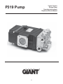
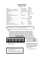
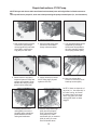
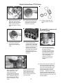
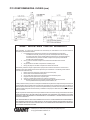
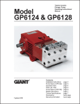
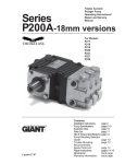
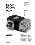
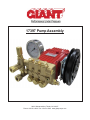
17397 Pump Assembly
900 N. Westwood Ave. Toledo, OH 43607
Phone: 419-531-4600 Fax: 419-531-6836 www.giantpumps.com
Table of Contents
Pages
Operating Instructions
3-5
P319R Pump Manual
6 -14
23280 Unloader Manual
15 -16
23422B Thermal Relief Valve
17
23910 Clutch Information
18
Bill-of-Materials
19
2
POWER PACK OPERATING INSTRUCTIONS
1) General Information
Giant Industries Packs are designed in accordance with customer specifications to suit a particular application.
Therefore, this manual should only be used to reference the power pack specified on the cover page. The individual operating instructions apply for the operation, maintenance, and service of the pump, valves (relief valve,
unloader valve, etc…), drive motor, and other accessories particular to this power pack.
2) Safety
This operating manual gives basic instructions, which are to be observed during installation, operation and
maintenance of the Power Pack components. Qualified personnel should read this operation manual, prior to the
assembly and operation of the power pack. A copy of this manual should be readily available and located near the
installation site.
2.1) Qualification and Training of Operation Personnel
The personnel responsible for operation, maintenance, inspection, and assembly must be adequately qualified. If
the staff does not have the appropriate knowledge to train they must be trained and instructed, which may be
performed by the manufacturer or supplier on behalf of the plant manager. The plant manager must make sure that
all participating personnel understand the contents of the operating manual.
2.2) Hazards in the event of Non- Compliance
Non-Compliance with the safety instructions may produce a risk to the personnel, as well as, to the environment
and the machine and may result in a loss of warranty claim.
For example, noncompliance may involve the following hazards:
·
Failure of important functions of the machine or plant
·
Failure of specified maintenance and repair
·
Exposure of people/environment to electrical, mechanical, and chemical hazards
2.3) Safe Operation
When operating the Power Pack, the safety instructions contained in this manual, safety instructions provided by
sources outside of Giant Industries and the Occupations Safety & Health Administration (OSHA) should be
observed.
2.4) Safety Instructions for Operator
If extreme hot or cold components promote hazards, they must be guarded against accidental contact. DO NOT
remove guards from moving parts (couplings, belt assemblies, etc…) during operation. Any leakage of hazardous
(toxic, hot fluids, etc…) fluids must be drained away to prevent any risks to persons or environment. Electrical
hazards should be eliminated. It may be necessary to seek out qualified, professional support to eliminate any of
the above hazards.
2.5) Safety Instructions for Maintenance, Inspection, and Assembly Work
It shall be the plant manager’s (or equivalent qualified personnel) responsibility to ensure that all maintenance,
inspection and assembly work is performed by authorized and qualified personnel who have adequately familiarized themselves with the subject matter by studying this manual in detail.
Any work on the machine shall only be performed when the Power Pack is at a standstill and all power has been
disconnected.
Pumps and Power Packs, which convey hazardous media, must be decontaminated.
Upon completion of work, all safety and protective facilities must be reinstalled and made operative again.
Prior to restarting the unit, the instructions listed under “Operation” are to be observed.
2.6) Unauthorized Alterations and Production of Spare Parts
No modifications shall be made to this equipment without the manufacturer’s knowledge or permission. In the
interest of safety, only authorized parts, spare parts or accessories shall be utilized on this equipment. The use of
unauthorized parts may exempt the manufacturer from liability and/or void any warranty.
3
POWER PACK OPERATING INSTRUCTIONS
2.7) Unauthorized Modes of Operation
The reliability of the delivered machine will only be guaranteed if it is used in the manner intended, in accordance
with Clause 1 of this manual. The specified limit values in the data sheets provided must, under no circumstances,
be exceeded.
3)
Transport and Storage
The Power Pack should always be transported horizontally. Storage for any length of time in a humid place or
where temperatures are below zero is to be avoided. The storage room much be well ventilated, as otherwise
dampness could damage the motor, pump gear, or other major components.
4)
Set-Up and Installation
The Power Pack is to be mounted onto a level and solid foundation (cement base). The location of the installation
has to be chosen so that maintenance work can be carried out easily.
4.1) Pump
A flexible hose must be used for the connection of the suction and discharge line (See Picture) so that any forces
coming from the pipeline cannot be transferred to the pump.
a) Suction Line
·
According to the water temperature of the suction side, the static pressure must be arranged so that the
NPSHA is always higher than the pump NPSHR. If necessary, a booster pump is to be built into the suction
line (between the supply water and high-pressure pump) which guarantees the required inlet pressure, which
is needed for a cavitation free environment.
·
The nominal width of the suction line has to be at least the same size as that of the pump inlet, better still is
one size larger. A filter or shut-off valve should not be installed directly in front of the inlet of the pump. The
suction line must only be used to feed the pump and should not be branched off to other machines, etc.
·
When installing more than one pump unit, each unit must be fed with its own separate suction line connected
to the supply source. The suction line leading to the pump must fall steadily from the supply source and is to
be installed without narrow elbow fittings and joints.
·
If the pump is connected to the local water supply, the regulations of the local water works must be adhered
to. A suction stabilizer is to be fitted in front of the plunger pump near the inlet to dampen suction pulsation.
b) Discharge Line
·
A safety valve must be installed in the high-pressure line directly after the discharge outlet of the pump. Shutoff fittings are not to be put between the pump and safety valve. The bypass line can be either feed back to
the supply source or placed in the open.
·
Important! The bypass line is to be fitted in such a way that nobody can be injured or by the sudden emergence of hot corrosive medium. The by pass line must be free of any shut-off fittings.
·
Make sure that air-turbulence does not occur when feeding back into the header tank.
·
An air vent should be built into the discharge line as near as possible to the pump.
·
The most optimal place for installing a pressure gauge is between the pump and safety valve. The second
outlet on the pump casing can also be used for this purpose.
·
The discharge line is to be mounted either horizontally or so that it rises steadily away from the pump.
4.2) Pulsation Dampener
The purpose of the pulsation dampener, if installed, is to dampen pulsation of the high-pressure pump and thus
avoid vibrations in the discharge line. Gas in the pulsation dampener should be pressurized to 50% of the max
system pressure. The gas pressure of the pulsation dampener must be checked regularly.
4.3) Motor
The motor is to be connected as per the information stated in the Operating Instructions and shown on the nameplate.
4.4) Filter/Strainer
Clean the filter insert regularly and check for any damage (based on the medium and operation period).
4
POWER PACK OPERATING INSTRUCTIONS
5) Operation
Check the oil level in the pump, and if necessary fill up as described per operating instructions.
Open all regulator valves and other shut-off fittings.
Start the motor briefly to check the direction of rotation. Pay careful attention to the specified direction of
rotation for the pump (arrows indicated on crankcase). To check the correct rotation, the pump must only be
dry run for a short period (approximately 30 seconds).
·
Install protective coverings.
·
Open water feed line.
·
Start pump. As there is a certain static pressure present in the suction line, the pump should be vented of air
immediately and begin conveying water. Listen carefully for a smooth-running sound. If the pump begins to
run irregularly or pulsate strongly, it can be that one of the three plungers is not vented. In this case, the pump
should be started and stopped at quick intervals to ease venting. Venting is also made easier if the vent tap in
the discharge line is opened.
Important! Danger of scalding when pumping hot water.
·
·
·
6) Maintenance and Repair
When carrying out maintenance or repair work on the pump, the respective points shown in the operating
instructions must be observed. We recommend that a first inspection of the pump unit be made after 50 hours of
operation.
a) Check V-belt for correct tensioning and excess wear.
b) Change pump oil as indicated in the operating instructions. This must normally be done at intervals of between
200-500/ hr, depending on the model. Oil checks are to be made weekly.
Important! Over tensioning of the V-belt can lead to permanent damage of associated parts in the gear end of the
pump. Please see further instructions pertinent to V-belts tensioning provided in the Operation Instructions.
7) Operating Instructions
Individual operating instructions are available for important components provided by Giant Industries. Additional
information for any product manufactured outside Giant Industries’ facilities maybe obtained by contacting the
manufacturer of the product. The plant manager and operating personnel should read and understand all operating
instructions prior to installation and maintenance.
5
Triplex Ceramic
Plunger Pump
Operating Instructions/
Repair and Service Manual
P319 Pump
6
INSTALLATION INSTRUCTIONS
Installation of the Giant Industries, Inc.,
pump is not a complicated procedure, but
there are some basic steps common to all
pumps. The following information is to be
considered as a general outline for installation. If you have unique requirements,
please contact Giant Industries, Inc. or your
local distributor for assistance.
4. Use of a dampener is necessary to minimize
pulsation at drive elements, plumbing, connections, and other system areas. The use of a
dampener with Giant Industries, Inc. pumps is
optional, although recommended by Giant
Industries, Inc. to further reduce system pulsation. Dampeners can also reduce the severity of
pressure spikes that occur in systems using a
shut-off gun. A dampener must be positioned
downstream from the unloader.
1. The pump should be installed flat on a base
to a maximum of a 15 degree angle of inclination
to ensure optimum lubrication.
5. When viewed from the side of the pump,
crankshaft rotation is clockwise on pumps with
left handed shafts and counterclockwise on
pumps with right handed shafts. Reverse rotation
may be safely achieved by following a few
guidelines available upon request from Giant
Industries, Inc. Required horsepower for system
operation can be obtained from the chart on
page 8.
2. The inlet to the pump should be sized for the
flow rate of the pump with no unnecessary
restrictions that can cause cavitation. Teflon
tape should be used to seal all joints. If pumps
are to be operated at temperatures in excess of
1600 F, it is important to insure a positive head to
the pump to prevent cavitation.
3. The discharge plumbing from the pump
should be properly sized to the flow rate to
prevent line pressure loss to the work area. It is
essential to provide a safety bypass valve
between the pump and the work area to protect
the pump from pressure spikes in the event of a
blockage or the use of a shut-off gun.
6. Before beginning operation of your pumping
system, remember: Check that the crankcase
and seal areas have been properly lubricated
per recommended schedules. Do not run the
pump dry for extended periods of time. Cavitation
will result in severe damage. Always remember
to check that all plumbing valves are open and
that pumped media can flow freely to the inlet of
the pump.
Finally, remember that high pressure operation in a pump system has many advantages. But, if it is
used carelessly and without regard to its potential hazard, it can cause serious injury.
IMPORTANT OPERATING CONDITIONS
Failure to comply with any of these conditions invalidates the warranty.
2. Pump operation must not exceed rated
pressure, volume, or RPM. A pressure relief
device must be installed in the discharge of the
system.
1. Prior to initial operation, add oil to the crankcase so that oil level is between the two lines on
the oil dipstick. DO NOT OVERFILL.
Use Giant oil - P/N 01153
(20W-50)
3. Acids, alkalines, or abrasive fluids cannot be
pumped unless approval in writing is obtained
before operation from Giant Industries, Inc.
Crankcase oil should be changed after the
first 50 hours of operation, then at regular
intervals of 500 hours or less depending on
operating conditions.
4. Run the pump dry approximately 10 seconds
to drain the water before exposure to freezing
temperatures.
7
Specifications
Model P319
U.S.
(Metric)
Volume ..................................................... Up to 4.8 GPM....... (18.2 LPM)
Discharge Pressure (Continuous) ............ Up to 2500 PSI ...... (175 bar)
Discharge Pressure (Intermittent) ............. Up to 3000 PSI ...... (200 bar)
Inlet Pressure ........................................... Positive Inlet Pressure Required
Stroke ...................................................... 0.31” ...................... 8mm
RPM ........................................................................................ Up to 3400 RPM
Plunger Diameter ..................................... 0.71” ...................... 18mm
Temperature of Pumped Fluids ................ Up to 160 oF .......... (71 oF)
Inlet Ports ................................................................................. (2) 1/2" BSP
Discharge Ports ....................................................................... (2) 3/8" BSP
Shaft Rotation .......................................... Top of pulley towards manifold
Crankshaft Diameter ................................................................ 24mm
Key Width ................................................................................ 8mm
Shaft Mounting ......................................................................... Either side1
Weight ..................................................... 16 lbs..................... (7.26 kg)
Crankcase Oil Capacity ........................... 14.2 fl.oz. ............... (0.42 liters)
Extended Crankcase Oil Capacity ............ 17 fl. oz. ................. (0.5 liters)
Consult the factory for special requirements that must be met if the pump is
to operate beyond one or more of the limits specified above.
NOTE:
1 In order to drive the pump from the side opposite the present
shaft extension, simply remove the valve casing from the crankcase and rotate the pumps 180 degrees to the desired position.
Be certain to rotate the seal case (item #20) as well, so that the
weep holes are down at the six o'clock position. Exchange the oil
fill and the oil drain plugs, also. Refer to the repair instructions as
necessary for the proper assembly sequence.
HORSEPOWER RATINGS:
P319 HORSEPOWER REQUIREMENTS
The rating shown are the power
RPM GPM 1500 PSI 2000 PSI 2500 PSI 3000 PSI*
requirements for the pump. Gas
3000 4.2
4.3
5.8
7.2
8.7
engine power outputs must be
3200 4.5
4.7
6.2
7.8
9.3
approximately twice the pump power
requirements shown above.
3450 4.8
5.0
6.6
8.3
9.9
*
Intermittent duty
SPECIAL NOTE:
The theoretical gallons per revolution
(gal/rev) is 0.0014.
To find specific outputs at various RPM,
use the formula: GPM = 0.0014 x RPM
8
We recommend a 1.15 service factor
be specified when selecting an
electric motor as the power source.
To compute specific pump horse
power requirements, use the
following formula:
HP = (GPM X PSI) / 1450
Exploded View - P319 Pump
9
P319 PUMP SPARE PARTS LIST AND REPAIR KITS
ITEM
1
2
3
3
3A
3B
4
5
5A
6
6A
6B
7
8
9
10
11
12
12A
13
14
15
16
16A
16B
16C
PART NO.
08326
06773
08410B
08410-LG
07190
13262A
08328
06273
08192
07188
01176-2
01196
08303
08491
07193
07225
08331
01086
07760
06508
06207
08333
08453
08367
08455
08456
DESCRIPTION
QTY.
Crankcase
1
Dipstick Assembly
1
Crankcase Cover, Short
1
Crankcase Cover, Extended 1
Oil Drain Plug
1
Gasket for Plug
1
O-Ring
1
Oil Drain Plug
1
Gasket
1
Screw, Short Cover
4
Spring Washer
12
Screw, Long Cover
4
Bearing Cover I
2
Sight Glass
1
O-Ring
1
Screw with Lock Washer
8
Radial Shaft Seal
1
Ball Bearing
1
Roller Bearing
1
Crankshaft
1
Straight Key
1
Connecting Rod
3
Plunger Assembly Complete, 3
Plunger Base
3
Plunger Pipe
3
Tension Screw
3
Plunger Packing Kits - # 09119
Item
23
23A
24
Part #
08477
08087
07904
Description
Grooved Seal, Black
Grooved Seal, Brown
Pressure Ring, 18mm
ITEM
16D
17
17A
18
19
20
21
22
23
23A
24
25
26
27
28
29
30
31
32
32X
33
34
36
36A
37
37A
PART NO.
07676
06542
22723
07770
08356-0010
08458
07780
12027
08477
08087
07904
08337
06349*
07849
07491
07906
07907
07853
06350*
07946A
07913
08363
13338
08486
07109
07661
DESCRIPTION
QTY.
Copper Washer
3
Wrist Pin
3
Clip Ring
6
O-Ring (Except A,B)
3
Oil Seal
3
Seal Case
3
O-Ring
3
O-Ring
3
V-Sleeve
3
Grooved Seal, Brown
3
Pressure Ring
6
Weep Return Ring
3
Valve Casing
1
Valve Seat
6
Valve Plate
6
Valve Spring
6
Valve Spring Retainer
6
O-Ring
6
Valve Plug
6
Valve Assembly, Complete 6
O-Ring
6
Hex Head Cap Screw
6
Plug, 3/8" BSP
l
Copper Crush Washer, 3/8” 1
Plug, 1/2" BSP
1
Seal
1
Valve Assembly Kit - # 09116
Qty.
3
3
6
Item
31
Part #
07853
Description
O-Ring
32X
33
07946A
07913
Valve Assy, Complete
O-Ring
Oil Seal Kit - # 09144
Item
Part #
Description
19
08356-0010 Oil Seal
Qty.
3
Torque Specifications
Position
Item#
Description
3B
6
10
16C
34
32
07190
07188
07225
08456
08363
06350
Oil Drain Plug w/ Gasket
Screw
Screw with Lock Washer
Tension Screw, Plunger
Hex Head Cap Screw, Valve Casing
Plug
Torque Amount
10
222 in.-lbs.
43 in.-lbs
85 in.-lbs.
220 in.-lbs.
222 in.-lbs.
59 ft.-lbs.
Qty.
6
6
6
PUMP SYSTEM MALFUNCTIONS
MALFUNCTION
The Pressure and/
the Delivery Drops
CAUSE
REMEDY
or Worn packing seals
Replace packing seals
Broken valve springs
Belt slippage
Worn or Damaged nozzle
Fouled discharge valve
Worn or Plugged relief valve on pump
Unloader
Replace springs
Tighten or Replace belt
Replace nozzle
Clean valve assembly
Clean, Reset, and Replace
worn parts
Check suction lines on inlet
of pump for restrictions
Check for proper operation
Water in Crankcase
High Humidity
Worn Seals
Reduce oil change intervals
Replace seals
Noisy Operating
Worn bearings
Replace bearings, Refill
crankcase oil with recommended
lubricant
Check inlet lines for restrictions
and/or proper sizing
Cavitations
Cavitation
Rough/Pulsating
Operation with
Pressure Drop
Worn packing
Replace packing
Inlet restriction
Check system for stoppage
air leaks, correctly sized
inlet plumbing to pump
Recharge/Replace accumulator
Accumulator pressure
Unloader
Cavitation
Check for proper operation
Check inlet lines for restrictions
and/or proper size
Pump Pressure as Drop Restricted discharge plumbing
at gun Rated, Pressure
Re-size discharge plumbing to flow
rate of pump
Excessive
Leakage
Worn plungers
Replace plungers
Worn packing/seals
Adjust or Replace packing seals
Excessive vacuum
Cracked plungers
Inlet pressure too high
Reduce suction vacuum
Replace plungers
Reduce inlet pressure
Wrong Grade of Oil
Giant oil is recommended
Improper amount of oil in crankcase
Adjust oil level to proper amount
High Crankcase
Temperature
Preventative Maintenance Check List & Recommended Spare Parts List
Every
Every
Every
3000
500
1500
Check
Daily Weekly 50 Hrs. Hours
Hours
Hours
Oil Level/Quality
X
Oil Leaks
X
Water Leaks
X
Belts, Pulley
X
Plumbing
X
Recommended Spare Parts
Oil Change
(1 quart) p/n 01153
X
X
Plunger Packing Kit
(1 kit/pump) See page 11
X
Oil Seal Kit
(1 kit/pump) See page 11
X
Valve Repair Kit
(1 kit/pump) See page 11
X
11
Repair Instructions- P319 Pump
NOTE: Always take time to lubricate all metal and nonmetal parts with a light film of oil before reassembly.
This step will ensure proper fit, at the same time protecting the pump nonmetal parts (i.e., the elastomers)
from cutting and scoring.
replace if damaged.
(#32X).
1. With a 24mm socket wrench,
remove the (3) discharge
valve plugs and (3) inlet valve
plugs (#32). Inspect the oring (#33) for wear and
2. Using a needle nose pliers,
remove the inlet and discharge valve assemblies
3. The valve assemblies can be
separated by inserting a
small screw driver between
the valve seat (#27) and its
valve spring retainer (#30).
4. Remove each o-ring (#31).
Inspect all parts for wear and
replace as necessary. Reassemble valve assy’s (32X) &
place in valve casing (26)
5. Apply one drop of Loctite
243 to valve plugs (32) and
tighten to 59 ft.-lbs.
6. Next, use a 6mm allen
wrench to remove the 6 hex
head cap screws (#34).
NOTE: If there are deposits of
any kind (i.e., lime deposits) in
the valve casing, be certain
the weep holes in the weep
return ring (#25) and valve
casing (#26) have not been
plugged.
7. Carefully slide the valve
casing (#26) out over the
plungers with a screwdriver
placed between the valve
casing and crankcase.
8. Remove weep return rings
(#25) from the plungers
(#16). Remove the seal
case (#20) from either
crankcases (#1) or manifold
(#26) by using a screwdriver as shown above.
12
Repair Instructions- P319 Pump
9.
Remove the pressure rings
(#24) and grooved seals
(#23) from the valve casing
(#26). Inspect parts for
wear and replace if necessary.
10. Remove the weep grooved
seals (23A) from the seal
case (#20). Remove the
pressure rings (#24).
11. Inspect o-rings (#21 and
22) and replace as necessary.
Reassembly sequence of
the P319 pump
12. Use a flat screw driver to
pry the oil seals (#19)
loose from the seal case
(#20).
15. Place each seal case (#20)
with o-rings (#21, 22) over
the plungers (#16). Be
certain the oil seal is
centered with the seal case
and tap firmly until the seal
case is seated squarely on
the crankcase (#1). Place
pressure ring (#24) in seal
case).
13. Check surfaces of the
plunger bases and plunger
pipes (#16B). A damaged
surface will cause accelerated wear on the seals.
Deposits of any kind must
be carefully removed from
the plunger surface. A
damaged plunger must be
replaced!
16. With the grooved side
pointed toward the valve
casing, place the weep
grooved seals (23A) over
each plunger and into each
seal case (#20).
13
14. If the oil seals (#19) were
removed, replace them with
the primary seal lip
(grooved side) towards the
crankcase and the dust lip
(tapered end) towards the
valve casing (#26). Lubricate the seal before
replacing. Install the oil
scraper (#18) over the
plunger.
17. Generously lubricate the grooved
seals (#23) and assemble these
items into the valve casing. Place
the weep return rings (#25) onto
each plunger (#16). Place the
pressure rings (#24) over the
plungers. Slide the valve casing
over the plungers and seat firmly.
Replace the 6 hex head cap screws
(#34) and tighten to 216 in.-lbs. in a
crossing pattern.
P319 PUMP DIMENSIONS - INCHES (mm)
GIANT INDUSTRIES LIMITED WARRANTY
Giant Industries, Inc. pumps and accessories are warranted by the manufacturer to be free from defects in
workmanship and material as follows:
1. For portable pressure washers and self-serve car wash applications, the discharge
manifolds will never fail, period. If they ever fail, we will replace them free of charge.
Our other pump parts, used in portable pressure washers and in car wash applications,
are warranted for five years from the date of shipment for all pumps used in NONSALINE, clean water applications.
2. One (1) year from the date of shipment for all other Giant industrial and consumer
pumps.
3. Six (6) months from the date of shipment for all rebuilt pumps.
4. Ninety (90) days from the date of shipment for all Giant accessories.
This warranty is limited to repair or replacement of pumps and accessories of which the manufacturer’s
evaluation shows were defective at the time of shipment by the manufacturer. The following items are NOT
covered or will void the warranty:
1. Defects caused by negligence or fault of the buyer or third party.
2. Normal wear and tear to standard wear parts.
3. Use of repair parts other than those manufactured or authorized by Giant.
4. Improper use of the product as a component part.
5. Changes or modifications made by the customer or third party.
6. The operation of pumps and or accessories exceeding the specifications set forth
in the Operations Manuals provided by Giant Industries, Inc.
Liability under this warranty is on all non-wear parts and limited to the replacement or repair of those products returned
freight prepaid to Giant Industries which are deemed to be defective due to workmanship or failure of material. A
Returned Goods Authorization (R.G.A.) number and completed warranty evaluation form is required prior to the return
to Giant Industries of all products under warranty consideration. Call (419)-531-4600 or fax (419)-531-6836 to obtain
an R.G.A. number.
Repair or replacement of defective products as provided is the sole and exclusive remedy provided hereunder and the
MANUFACTURER SHALL NOT BE LIABLE FOR FURTHER LOSS, DAMAGES, OR EXPENSES, INCLUDING
INCIDENTAL AND CONSEQUENTIAL DAMAGES DIRECTLY OR INDIRECTLY ARISING FROM THE SALE OR
USE OF THIS PRODUCT.
THE LIMITED WARRANTY SET FORTH HEREIN IS IN LIEU OF ALL OTHER WARRANTIES OR REPRESENTATION, EXPRESS OR IMPLIED, INCLUDING WITHOUT LIMITATION ANY WARRANTIES OR MERCHANTABILITY
OR FITNESS FOR A PARTICULAR PURPOSE AND ALL SUCH WARRANTIES ARE HEREBY DISCLAIMED AND
EXCLUDED BY THE MANUFACTURER.
GIANT INDUSTRIES, INC., 900 N. Westwood Ave., P.O. Box 3187, Toledo, Ohio 43607
PHONE (419) 531-4600, FAX (419) 531-6836, www.giantpumps.com
© Copyright 2008 Giant Industries, Inc.
14
Model
23280
Direct Mount Pressure Actuated
Unloader with bypass connection
OPERATING CONDITIONS
Max Flow: ............................... 6.6 GPM ....... 25 L/min
Pressure: ............................... 0-4000 PSI ... 0-275 Bar
Maximum Temp.: .................... 1940 F ........... 90 0 C
Weight: .................................. 2.0 lbs. .......... 0.91 Kg
Inlet Port: ...................................................... 1/2" FNPT
Discharge Port (injector): ............................. 3/8" MNPT
Discharge Port (w/o injector): ....................... 3/8" FNPT
Bypass: ........................................................ Internal
Item #
1
2
3
4
5
6
7
8
9
10
11
12
14
15
16
17
18
19
20
21
22
23
24
25
26
27
28
Part#
05137
08550
05134
07770*+
08553*+
07915*+
05131
08691*
22659*+
08563*
05139
05133
08549
08558
08555
08559*+
12326*+
07913*+
12328
12340
12325
08564*+
08566
13443
08548
13442
08541
Description
Adjusting Spring Cap
Pressure Spring
Nut
O-Ring
Support Ring
O-Ring, Piston
Unloader Body
Piston
O-Ring
Seat
Bypass Fitting
Inlet Tube
Spring Retainer
Guide Plug
Piston Rod
Support Ring
O-Ring
O-Ring
Kick Back Valve Spring
Kick back Valve Retainer
Kick Back Valve Cone
O-Ring
O-Ring
Discharge Banjo Bolt
Seal Ring
Inlet Banjo Bolt
Seal Ring
*09321
Full Repair Kit
(4-6,8-10, 17-19 & 23)
Seal Repair Kit
(4-6, 9, 17-19 & 23)
+09322
15
Qty.
1
1
1
1
1
2
1
1
1
1
1
1
1
1
1
1
1
1
1
1
1
1
1
1
2
1
2
Installation and Operation Instructions
1) The valve should be tension-free; therefore, loosen handwheel (3) as far as possible.
2) While the gun is open, turn the handwheel (3) in a clockwise motion until desired pressure is reached.
Important! If the nozzle orifice is too small to allow all the fluid to run through the hole after the required operating pressure is reacted, on no account is the valve to be adjusted higher than the maximum operating pressure of the pump.
Disassembly and Reassembly of the 23280 Unloader
1. Remove Adjusting Spring Cap (1) and remove Pressure Spring (2) and Spring Retainer (14).
2. Pull Inlet Tube (12) off Bypass Fitting (11) and unscrew Bypass Fitting(11) from Unloader Body (7).
3. Insert a small screwdriver or allen wrench in the bottom of the Bypass Fitting (11) and push the Seat (10)
out of the Bypass Fitting. NOTE: Use caution to prevent scratching or nicking the chamfered area of the
Seat.
4. Insert a 9/32" deep-well socket onto the top of the Piston Rod (16) and a ½” deep-well socket on to the
Piston (8). Remove the Piston from the Piston Rod.
5. Unscrew the Guide Plug (15) from the top of the Unloader Body (7). Push the Piston Rod (16) out of the
Guide Plug.
6. Loosen the Kick Back Valve Retainer (21) or Siphon Injector (21) and remove the Kick Back Valve Cone
(22) and Kick Back Valve Spring (20).
7. Inspect all o-rings and mating parts. Replace with parts from the kit.
8. Reassemble in reverse order.
Note: Lightly grease all parts before reinstalling.
Giant Industries, Inc.
900 N. Westwood Ave., Toledo, Ohio 43607
PHONE: 419-531-4600 FAX: 419-531-6836
www.giantpumps.com © Copyright 2009 Giant Industries, Inc.
7/11 23270/23280.PMD
16
Automatic Thermal
Relief Valves
Model
23400 Series
Item
1
2
3
4
5
6
Part #
06416
06351*
06355
23402
06356
06352
Description
Qty.
Deflector
1
Thermal Body, 1/2"
1
O-Ring
1
Power Pill
1
Spring
1
Spring Retainer
1
OPERATING CONDITIONS
Max Inlet Pressure:
Max System Flow:
Preset Temperature:
Inlet Port Size:
Outlet:
Weight:
Dimensions:
90 PSI
8 GPM
140o F
23420B 1/4" NPT
23421B 3/8" NPT
23422B 1/2" NPT
7/8" Hose Barb
(without deflector)
3 Ounces
7/8" X 1.8"
* For 1/4" Thermals, an adapter (p/n 06399 is included)
* For 3/8" Thermals, an adapter (p/n 06400 is included)
Installation:
The Series 23400 Automatic Thermal Relief Valve is a must for any system utilizing a closed loop bypass line or internal
bypass. The valve is designed to protect your pump and accessories against extreme heat when the pump is in bypass.
When the temperature of the water in the bypass line reaches the preset temperature of the valve a small amount of hot
water is released which is replaced by cooler supply water. This in turn lowers the temperature of the water in the bypass line
thus signaling the valve to close. NOTE: The thermal relief valve works most effectively on pumping systems having positive
inlet pressures.
Closed Loop Bypass Line Systems:
For pumping systems whose bypass line is routed back to the pump inlet (closed loop), installation of the Giant thermal relief
valve should be in this loop. By installing a "tee" in the bypass line the thermal relief valve can effectively be installed to detect
heat build up during pump bypass. A 1/2" (I.D.) hose should be attached to the end of the valve to direct the hot discharge
water to a safe location.
Internal Bypass Pumps:
On pumps equipped with an internal bypass system, (such as the Giant Series R51000) the thermal relief valve can be
utilized by installing a "tee" at the inlet of the pump. The Giant thermal relief valve can be placed in a branch of the "tee" where
it will sense the increased water temperature. A 1/2" (I.D.) hose should be attached to the end of the valve to direct the hot
discharge water to a safe location.
Repair:
Because of it's unique construction the Giant Thermal Relief valve is not rebuildable. The design utilized will provide years of
trouble free service.
Giant Industries, Inc.
900 N. Westwood Ave., P.O. Box 3187, Toledo, Ohio 43607
419-531-4600 Fax: 419-531-6836 www.giantpumps.com © Copyright 2004 Giant Industries, Inc.
17
Instructions for 23910 clutch assembly
(For P200 and P300 Series Pumps)
Parts List
Item # Part #
1
06429
2
06521
3
06522
4
10440
6
08198
7
08198
Description
24mm Clutch
Mounting Flange
1/4-20 Hex Nut
Hex Head Screw
Fender Washer
M8-1.25 Screw
Qty
1
1
4
4
1
1
Assembly and Installation Instructions
1. Remove the bearing cover on the pump with a 10 mm hex wrench.
2. Place the mounting plate (2) over the crankshaft and secure with existing bearing cover
screws.
3. Secure clutch (1) to mounting flange by sliding clutch over crankshaft and attaching with
screws (4) and hex nuts (3). Secure set screw on pulley shaft.
4. Thread the M8-1.25 screw (7) and Fender Washer (6) over the hub of the clutch (1) into
the crankshaft of the pump.
5. Attach lead wire to (+) or pressure flow / switch as desired.
6. Attach "A or AX section" belt of required length
7. Engage and disengage the clutch several times to ensure it is functioning properly. If full torque will be
required from the pump immediately, the clutch should be properly burnished. (Burnishing involves cycling
the clutch at a reduced speed not more than 4 times per minute so the surfaces can mate together. In most
applications, 20-50 cycles are required for burnishing.)
NOTE: If an operation manual is needed for the above pump models, please consult your local distributor.
18
BILL OF MATERIALS
Part #
17397 (P319RUT Pump and Clutch Assembly)
COMPONENT#
DESCRIPTION
QTY
P319R
Pump
1
23280
Unloader
1
23422B
Thermal Relief Valve
1
23910
Clutch Assembly
1
25000-3600
Pressure Gauge
1
900 N. Westwood Ave. Toledo, OH 43607
Phone: 419-531-4600 Fax: 419-531-6836 www.giantpumps.com
19
Giant Industries, Inc.
900 N. Westwood Ave.
Toledo, OH 43607
419-531-4600
419-531-6836 Fax
www.giantpumps.com
© Copyright 2011 Giant Industries, Inc.
01/12 PP17397.PMD
20