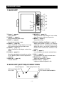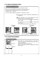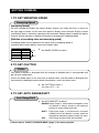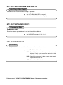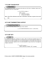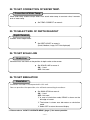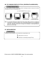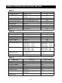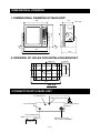
1
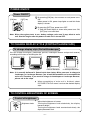
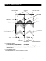
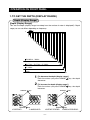
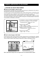
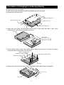
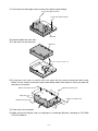
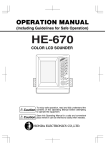
OPERATION MANUAL HE-7300 COLOR LCD ECHO SOUNDER INTRODUCTION We thank you very much for your purchasing our product HE-7300. ■ Please be sure to read this operation manual carefully and understand what it describes before you operate this unit in order to keep your safety. ■ After you read this manual, please keep it at the place where you will not lose or break so as to read soon when it is necessary. ■ In case that you resell or transfer this unit, please give it to the new owner. ■ We will not be responsible for product liability (PL) law relating to damage to human or physical property from operation which is not described on this manual or wrong operation. DEFINITION OF SYMBOL MARK [CAUTION FOR SAFETY] ������ : incur the accident resulting in the death or serious wound unless you keep the descriptions. ������� : Be in danger of incurring the accident resulting in the death or serious wound unless you keep the descriptions. ������� : Be in danger or incurring the slight wound to human or damage to other physical property unless you keep the descriptions ・ Do not reproduce a part or all of contents described on this manual without our approval. ・ Please understand that the unit may differ from contents described on this manual partially due to change of specifications and so on. ・ If you have questions, errors or omission on this manual, may we trouble you to inform us? CONTENS CAUTION ON SAFETY (PLEASE MAKE SURE TO READ.) ・・・・・・・・・・・ 1. HANDLING OF MAIN UNIT ・・・・・・・・・・・・・・・・・・・・・・・・・・・・・・・・・・・ 2. HANDLING OF CABLES ・・・・・・・・・・・・・・・・・・・・・・・・・・・・・・・・・・・・・ 3. HANDLING OF TRANSDUCER AND WATER TEMPERATURE SENSOR・・・・・・・・・・・・・・・・・・・・・・・・ 1 1 2 2 CAUTION ON OPERATION ・・・・・・・・・・・・・・・・・・・・・・・・・・・・・・・・・・・・・・・・ 3 FEATURES ・・・・・・・・・・・・・・・・・・・・・・・・・・・・・・・・・・・・・・・・・・・・・・・・・・・・・・ 3 DESCRIPTIONS・・・・・・・・・・・・・・・・・・・・・・・・・・・・・・・・・・・・・・・・・・・・・・・・・・ 4 1. MAIN UNIT ・・・・・・・・・・・・・・・・・・・・・・・・・・・・・・・・・・・・・・・・・・・・・・・・・ 4 2. MAIN UNIT (BOTTOM)/CONNECTIONS・・・・・・・・・・・・・・・・・・・・・・・・ 4 HOW TO OPERATE MENU ・・・・・・・・・・・・・・・・・・・・・・・・・・・・・・・・・・・・・・・・ 5 BASIC OPERATION POWER ON/OFF ・・・・・・・・・・・・・・・・・・・・・・・・・・・・・・・・・・・・・・・・・・・・・・・・・ 6 TO CHANGE DISPLAY STYLE (PORTRAIT/LANDSCAPE)・・・・・・・・・・・・ 6 TO CONTROL BRIGHTNESS OF SCREEN・・・・・・・・・・・・・・・・・・・・・・・・・・ 6 HOW TO SEE THE DISPLAY ・・・・・・・・・・・・・・・・・・・・・・・・・・・・・・・・・・・・・・・ 7 OPERATION ON FRONT PANEL ・・・・・・・・・・・・・・・・・・・・・・・・・・・・・・・・・・・ 8 1. TO SET THE DEPTH (DISPLAY RANGE) ・・・・・・・・・・・・・・・・・・・・・・・ 8 2. TO SET SHIFT (DISPLAY RANGE SHIFT) ・・・・・・・・・・・・・・・・・・・・・・ 9 3. TO ADJUST SENSITIVITY・・・・・・・・・・・・・・・・・・・・・・・・・・・・・・・・・・・ 10 4. TO SET A-MODE ・・・・・・・・・・・・・・・・・・・・・・・・・・・・・・・・・・・・・・・・・・・ 12 5. TO SHOW/SET THE EXPANSION MODE・・・・・・・・・・・・・・・・・・・・・・ 12 6. TO MOVE EXPANDED AREA ・・・・・・・・・・・・・・・・・・・・・・・・・・・・・・・・ 13 7. TO SHOW THE MARKER ・・・・・・・・・・・・・・・・・・・・・・・・・・・・・・・・・・・ 13 SETTING ON MENU ・・・・・・・・・・・・・・・・・・・・・・・・・・・・・・・・・・・・・・・・・・・・・ 1. TO SET SWEEPING SPEED・・・・・・・・・・・・・・・・・・・・・・・・・・・・・・・・・ 2. TO SET CLUTTER・・・・・・・・・・・・・・・・・・・・・・・・・・・・・・・・・・・・・・・・・・ 3. TO SET AUTO RANGE/SHIFT ・・・・・・・・・・・・・・・・・・・・・・・・・・・・・・・ 4. TO SET AUTO RANGE MAX. DEPTH ・・・・・・・・・・・・・・・・・・・・・・・・・ 5. TO SET EXPANSION RATE・・・・・・・・・・・・・・・・・・・・・・・・・・・・・・・・・・ 6. TO SET AUTO GAIN ・・・・・・・・・・・・・・・・・・・・・・・・・・・・・・・・・・・・・・・・ 7. TO SET CLEAN ECHO ・・・・・・・・・・・・・・・・・・・・・・・・・・・・・・・・・・・・・・ 8. TO SET TRNASMITTING OUTPUT ・・・・・・・・・・・・・・・・・・・・・・・・・・・ 9. TO SET STC ・・・・・・・・・・・・・・・・・・・・・・・・・・・・・・・・・・・・・・・・・・・・・・・ 10. TO SET BACKGROUND COLOR ・・・・・・・・・・・・・・・・・・・・・・・・・・・・ 11. TO SET COLOR TONE・・・・・・・・・・・・・・・・・・・・・・・・・・・・・・・・・・・・・ 12. TO SET COLOR CONFIGURATION ・・・・・・・・・・・・・・・・・・・・・・・・・ 13. TO SET WATER TEMP. GRAPH ・・・・・・・・・・・・・・・・・・・・・・・・・・・・・ 14. TO SET FISH ALARM・・・・・・・・・・・・・・・・・・・・・・・・・・・・・・・・・・・・・・ 15. TO SET WATER TEMP. ALARM ・・・・・・・・・・・・・・・・・・・・・・・・・・・・・ 16. TO SET DEPTH ALARM ・・・・・・・・・・・・・・・・・・・・・・・・・・・・・・・・・・・ 17. TO CHANGE UNIT OF DEPTH READOUT ・・・・・・・・・・・・・・・・・・・ 18. TO CHANGE UNIT OF WATER TEMP. READOUT ・・・・・・・・・・・・・ 19. TO SET PULSE LENGTH ・・・・・・・・・・・・・・・・・・・・・・・・・・・・・・・・・・ 20. TO SET SUPER RANGE ・・・・・・・・・・・・・・・・・・・・・・・・・・・・・・・・・・・ 21. TO SHOW DUAL FREQUENCY DISPLAY ・・・・・・・・・・・・・・・・・・・・ 22. TO SET CORRECTION OF WATER TEMP. ・・・・・・・・・・・・・・・・・・・ 23. TO SELECT SIZE OF DEPTH READOUT ・・・・・・・・・・・・・・・・・・・・ 24. TO SET SCALE LINE ・・・・・・・・・・・・・・・・・・・・・・・・・・・・・・・・・・・・・・ 25. TO SET SIMULATION・・・・・・・・・・・・・・・・・・・・・・・・・・・・・・・・・・・・・・ 26. TO CHANGE DISPLAY STYLE (PORTRAIT/LANDSCAPE) ・・・・・ 27. INITIALIZATION ・・・・・・・・・・・・・・・・・・・・・・・・・・・・・・・・・・・・・・・・・・・ 14 14 14 14 15 15 15 16 16 16 17 17 17 18 18 18 19 19 19 20 20 20 21 21 21 21 22 22 MENU CONTENTS AND FACTORY SETTING ・・・・・・・・・・・・・・・・・・・・・・ 23 REFERENCE DIMENSIONAL DRAWING ・・・・・・・・・・・・・・・・・・・・・・・・・・・・・・・・・・・・・・・ 24 1. DIMENSIONAL DRAWING OF MAIN UNIT ・・・・・・・・・・・・・・・・・・・・ 24 2. DRAWING OF HOLES FOR INSTALLING BRACKET ・・・・・・・・・・・ 24 CONNECTION WITH MAIN UNIT ・・・・・・・・・・・・・・・・・・・・・・・・・・・・・・・・・・ 24 INSTALLATION OF MAIN UNIT ・・・・・・・・・・・・・・・・・・・・・・・・・・・・・・・・・・・ 25 1. PROCEDURE OF INSTALLING MAIN UNIT・・・・・・・・・・・・・・・・・・・・ 25 INSTALLATION OF TRANSDUCER・・・・・・・・・・・・・・・・・・・・・・・・・・・・・・・・ 26 Installation of transducer (Thru-hull) ・・・・・・・・・・・・・・・・・・・・・・・・・・・・・ 26 INSTALLATION OF WATER TEMP. SENSOR ・・・・・・・・・・・・・・・・・・・・・・・ 27 STANDARD COMPOSITION ・・・・・・・・・・・・・・・・・・・・・・・・・・・・・・・・・・・・・・ 28 OPTIONS・・・・・・・・・・・・・・・・・・・・・・・・・・・・・・・・・・・・・・・・・・・・・・・・・・・・・・・ 28 GENERAL IMFORATION OF FISH FINDER ・・・・・・・・・・・・・・・・・・・・・・・・ 1. THEORY OF ECHO FISH FINDER ・・・・・・・・・・・・・・・・・・・・・・・・・・・ 2. HOW TO DISTINGUISH THE FISH SCHOOL ・・・・・・・・・・・・・・・・・・ 3. HOW TO DISTINGUISH THE FISH VOLUME・・・・・・・・・・・・・・・・・・・ 4. HOW TO DISTINGUISH THE NATURE OF BOTTOM・・・・・・・・・・・・ 29 29 30 30 30 TROUBLE SHOOTING ・・・・・・・・・・・・・・・・・・・・・・・・・・・・・・・・・・・・・・・・・・・ 31 SPECIFICATIONS ・・・・・・・・・・・・・・・・・・・・・・・・・・・・・・・・・・・・・・・・・・・・・・・ 33 CAUTION ON SAFETY (PLEASE MAKE SURE TO READ.) This section explains the important cautions in order to prevent the person who will use our product or other persons from human damage or damage to their property. 1. HANDLING OF MAIN UNIT ������ ● High voltage is applied to the inside of unit. No one besides authorized technician should disassemble or modify it. Unless you keep it, the accident resulting in the electric shock will occur. ※ Please be sure to consult with dealer when you want to repair. ������� ● Do not install it in simple method. It causes to the accident like human damage. ※ Please be sure to install correctly according to descriptions on "Installation of the unit" of this manual. ● Do not use the information displayed on the screen of unit for navigation directly. It causes to the marine disaster. ※ Please be sure to use the official marine charts for navigation judgment. ● Do not put the power on in the presence of flammable materials. It causes to firing. ● Do not use the power supply besides the specified ones. It causes to heating or firing. −1− 2. HANDLING OF CABLES ������� ● Be sure to use the specified power supply cable and fuse. It cause to heating or firing. ● Do not leave the power plug as it is while it is pulled out of the unit. If the plug gets wet, it causes to heating or firing due to short circuited. ● Be sure to wire in order to prevent the cables from interfering to operate boat. If feet of crews or operating equipments are caught in cables, it causes to the accident. ※ Do not put the heavy objects on cables or do not bend cables excessively. ● Do not disassemble or modify the cables. It causes to heating, firing or electric shock. ● Do not use the damaged cables. It causes to firing or electric shock. ������� ● Do not pull the cable when you pull out the plug. It causes to firing or electric shock because the cable is broken. ※ When you pull out the plug, be sure to have it in your hand and pull it. 3. HANDLING OF TRANSDUCER AND WATER TEMPERATURE SENSOR ������ ● Work on the board is too unstable and risky. Installation and maintenance of transducer and water temperature sensor should be done after you land and fix the boat. Unless you keep it, human damage resulting in death or serious wound will occur. ※ Please ask to shop for installation. ������� ● Installation of the transducer or water temperature sensor inside the hull with adhesive should be done while you ventilate well inside the boat. Volatile gas from solvent or etc. causes to toxic symptoms. ● When you work using electric tools, please keep your hands dry. If you hands are wet, it causes to electric shock. ● When you pull out or insert the plug of transducer or water temperature sensor, please be sure to turn the power switch off. It causes to electric shock. ● Perfect waterproof treatment should be done when you install the transducer or water temperature sensor through the hull. If waterproof is not sufficient, it causes to marine disaster because water comes in. ※ Please ask to shop for installation. −2− CAUTION ON OPERATION 1. Power OFF when the engine starts to run! When the engine starts to run, voltage of battery varies heavily. It may influence to the unit. Be sure to put the power switch of the unit off when you start to run the engine. 2. Power supply should be 11-35VDC! Please make sure to operate the unit at 11-35VDC of power supply voltage. 3. Avoid the place where it is high temperature! When temperature of the unit exceeds 70˚C, it causes to faulty. Please be more careful to operate or store it under direct sun ray in the summer time and use it carefully where it is in the shade as possible. 4. Prohibited to use the organic solution! Do not clean the unit with organic solution like thinner, alcohol or etc. as some parts of the unit and panel are coated or made by plastic. In case it is too dirty, soak the soft cloth in a synthetic detergent and clean with it after wringing well. 5. Be careful for water-spray! Water-spray on the unit causes to faulty, install at the place where there is no water-spray. FEATURES ● Clear viewing applying high quality 10.4 inch VGA color LCD ● Bottom lock expansion function as well as bottom expansion (Auto, Manual) are incorporated. ● Beginners can operate without worry using Auto Range Control and Auto Gain Control. ● You can install the display in both width and length as well as you can change the display Portrait or Landscape. ● You can install at any place using compact and light case. −3− DESCRIPTIONS 1. MAIN UNIT ① ③ ⑤ ⑦ ⑨ ⑧ ⑫ ⑩ ⑭ ① Power ( → page 6 ) Power ON/OFF ② RANGE ( → page 8 ) Set the displayed depth range. ③ SHIFT ( → page 9 ) Move displayed depth range. ④ GAIN 1 ( → page 10 ) Adjust sensitivity of right display on single freq. mode and dual freq. parallel mode. ⑤ GAIN 2 ( → page 11 ) Adjust sensitivity of left display on dual freq. mode. ⑥ ZOOM ( → page 12 ) Move the expanded area toward sea surface or sea bottom (When manual expansion is selected) . ⑦ MODE A ( → page 12 ) A mode ON/OFF ② ④ ⑥ ⑪ ⑬ ⑧ MODE B ( → page 12 ) Switch Normal mode, Bottom Lock mode, Auto Expansion or Manual Expansion. ⑨ MENU ( → page 5 ) Show Menu mode ⑩ Direction (Up/Down/Left/Right) ( → page 5 ) When menu mode is shown, it is used for selecting items or changing the setting. When the menu is not shown, Up/Down key moves cursor toward sea surface or sea bottom. ⑪ SET ( → page 5 ) It is used when you execute selected items. ⑫ CLR ( → page 5 ) It is used when you want to cancel menu. ⑬ Brightness ( → page 6 ) Adjust the brightness of display. ⑭ Power Lamp ( → page 6 ) It lights on when the power is ON. 2. MAIN UNIT (BOTTOM)/CONNECTIONS ��������������� ����������������������� �������������������� �������� ������������φ������� ※ ���������������������������� −4− HOW TO OPERATE MENU How to operate menu You can change contents of item which you set by selecting menu item using [MENU] key, [DIRECTION]key, [SET] key or [CLR] key. ���������� ��������� ��������� ����������� ������������ ����������� �������������� key 1 [MENU] ① Menu 1 is shown pressing MENU key. ② Menu 2 is shown pressing MENU key again. ③ Menu 3 is shown pressing MENU key one more again. ④ Menu display is closed and normal display is shown pressing MENU key one more again. ⑤ On the display of setting water temp. alarm and depth alarm, by pressing MENU key it returns to previous display. Up/Down key 2 [DIRECTION] ① Blue selected item moves upward pressing Up key. ② When Up key is pressed while selected item is located on the top item, blue selected item moves to bottom. ③ Blue selected item moves downward pressing Down key. ④ When Down key is pressed while selected item is located on the bottom item, blue selected item moves to top. Blue selected item becomes changeable item. Left/Right key 3 [DIRECTION] ① Set value of item selected in blue is changed by Left/ Right key. After set value is changed, new set value is effective. ② When you press Right key on selected item of water temp. alarm or depth alarm, it moves to set mode of alarm. key 4 [SET] ① For changing display style (Portrait/Landscape) and initialization, when you decide set value, press SET key after changing set value. When SET key is executed, set value is changed and it returns to Normal display. key 5 [CLR] ① When you want to cancel the menu display in the middle of setting, it returns to Normal display from any menu display pressing CLR key. −5− POWER ON/OFF Power ON/OFF [ON] key [OFF] key pressing [ON] key, alarm comes on and power turns 1 By ON. When power is ON, power lamp lights on and fish finder display is shown. pressing [OFF] key, power turns OFF. 2 By ※ Until fish finder display is shown after power turns ON, [OFF] key is not activated. Note: When the engine starts to run, battery voltage varies and it may affect to main unit. Start the engine after the power of main unit is turned OFF. TO CHANGE DISPLAY STYLE (PORTRAIT/LANDSCAPE) To change display style (Portrait/Landscape) You can change the display (landscape, portrait, landscape reverse and portrait reverse) according to the status of installing the unit. ���������� ����������� ������������������ ������������������� Note: It is normally delivered in Portrait style from factory. When you want to change to Landscape or Landscape Reverse, you should disassemble and re-assemble the main unit. Therefore, if you want to change to Landscape or Landscape Reverse, please ask to the shop. assembling of main unit is finished, select ・ When PICTURE STYLE on menu 3 and set the desired display style. TO CONTROL BRIGHTNESS OF SCREEN Control of brightness dark bright Adjust the brightness of screen. ・ Turning the brightness knob clockwisely, the display Brightness knob becomes bright. Turning the brightness knob counterclock-wisely, the display becomes dark. −6− HOW TO SEE THE DISPLAY ����������������� ��������� ������������������ ����������� ������ ���������※ ������ �������� �������������� ������������������� ����� ���������� �����������※ ����������� ������������������� ※ As for frequency readout; ・ In case main unit is single frequency: No indication ・ In case main unit is dual frequencies: L: Low Frequency H: High Frequency However, in case of dual frequency parallel display, position of readout moves. (Refer to page 11 ) ※ As for water temp. readout; When optional water temp. sensor is connected, it is shown. −7− OPERATION ON FRONT PANEL 1. TO SET THE DEPTH (DISPLAY RANGE) Depth (Display Range) [Depth (Display Range)] This sets the depth (display range; how deep from the surface of water is displayed?). Depth range you can set differs depending on frequency. 0 5 8 10 15 20 30 40 50 60 80 100 125 150 180 200 250 300 400 50&200 kHz、200 kHz 500 600 40-75kHz、50-55kHz、85-90kHz 800 1000 32-40kHz 1500 28kHz 2000m decrease the depth (display range)] 1 [To Each time when you press RANGE key, the depth decreases. increase the depth (display range)] 2 [To Each time when you press RANGE key, the depth increases. ������������� ������������� ���������� ����������� ������������� ������������� ������������������ ������������������� −8− 2. TO SET SHIFT (DISPLAY RANGE SHIFT) Shift (Shift of display range) [Shift (Shift of display range)] You can shift the initial displaying depth downward. For example, when you shift 10m downward at 0-8m depth range, initial display depth becomes to 10m and display range becomes to 10-18m. 0 8m 10 m shift 8 10 8m 18 shift to shallow depth] 1 [To Each time when you press SHIFT key, the display range becomes shallow. shift to deep depth] 2 [To Each time when you press SHIFT key, the display range becomes deep. ������������� ������������� ���������� ����������� ������������� ������������� ������������������ ������������������� −9− 3. TO ADJUST SENSITIVITY In case of single frequency display This describes operation for single frequency display. ※ You can change sensitivity by GAIN1 key or GAIN2 key. ※ Single frequency display or dual frequency display is selected on menu. ( → page 20 ) ※ When the unit is delivered from factory, dual frequency display mode is set. [Gain] This adjusts the sensitivity to distinguish the bottom or fish school easily. 32 steps of sensitivity from 0 to 31 is displayed in bar. Optimum sensitivity is that second reflection from bottom is barely displayed. [Second reflection] First received echo reflected from bottom is called the first reflection. It's first reflection reflected from the surface of water goes toward the bottom again. The next reflection from bottom is called the second reflection. Normally, it's second reflection is shown on the twice depth of the actual bottom (first reflection). decrease sensitivity] 1 [To Each time when you press GAIN1 ������ �������� ������� ���������� key, gain bar becomes short and the sensitivity decreases. increase sensitivity] 2 [To Each time when you press GAIN1 key, gain bar becomes long and the sensitivity increases. �������������� �������������� �������������� ���������� �������������� ����������� ������������������ ������������������� <Too poor sensitivity> <Good> <Too much sensitivity> Bottom is shown in green or white. As second reflection is shown, it is easy to distinct the fish school. As plankton, stains in water, and etc. are shown, it is difficult to distinct the fish school. −10 − In case of dual frequency display In case of dual frequency display, you can change the sensitivity on right side of screen by GAIN1 key and the sensitivity on left side of screen by GAIN2 key. GAIN2 Gain Readout GAIN1 1 Adjust sensitivity on left side of screen by GAIN2 key [To decrease sensitivity] Each time when you press GAIN2 key, gain bar becomes short and the sensitivity decreases. [To increase sensitivity] Each time when you press GAIN2 key, gain bar becomes long and the sensitivity increases. 2 Adjust sensitivity on right side of screen by GAIN1 key [To decrease sensitivity] Each time when you press GAIN1 key, gain bar becomes short and the sensitivity decreases. <In case of "Low+High"> [To increase sensitivity] Each time when you press GAIN1 key, gain bar becomes long and the sensitivity increases. �������������� �������������� ���������� ����������� �������������� �������������� ������������������ ������������������� −11 − 4. TO SET A-MODE A-mode It is displayed on the right side of screen (between fish finder display and depth calibration) and it's width changes according to strength of reflected signal. Strong response is indicated thick and weak signal is indicated thin. MODE A key 1 A-Mode is shown pressing MODE A key. 2 By pressing MODE A key again, A-Mode is cancelled. 5. TO SHOW/SET THE EXPANSION MODE Expansion Mode [Expanded display] Expanded display is shown on the left half of screen. In case of dual frequency, frequency's expanded display shown on right side of screen is displayed on the left side of screen. �������� time when MODE B key is pressed, next mode is ・ Each selected. NORMAL DISPLAY: Expansion display is cancelled and normal display is shown. ���������� BOTTOM LOCK: Bottom contour is indicated as a straight line and expansion view of certain area from it's contour is shown. AUTO EXPANSION: Expanded display up or down in the center of bottom. MANUAL EXPANSION: Expanded display up or down in the center of optional position. You can mode expanded area by [ZOOM] key as you wish. ※ Displayed range varies depending on "Expansion Rate." (Refer to page 15 ). −12 − 6. TO MOVE EXPANDED AREA To move expanded area You can move and see expanded area to top or bottom of display. ※ You can not operate ZOOM key except for manual expansion mode. ※ Expansion rate is selected among 2 times, 4 times and 8 times. (Expansion Rate → page 15 ) ※ It is set to 4 times expansion mode when it is delivered from factory. expansion mode to MANUAL EXPANSION with 1 Set MODE B key. expanded area (range indicated by green 2 Move expansion mark) up or down by ZOOM key. Each time when you press ZOOM key, it approaches to sea surface. Each time when you press ZOOM key, it approaches to sea bottom. ※ To cancel Expansion display, press MODE B key.. ������������ ������������ ������������ ���������� ����������� ������������ ������������������ ������������������� 7. TO SHOW THE MARKER To show the marker Up key Down key Marker Down key is pressed while menu is not shown, ・When horizon line (marker) is indicated on the screen and it's line moves downward. Marker moves upward pressing Up key. Depth at the position of marker is indicated with number above marker. −13 − SETTING ON MENU 1. TO SET SWEEPING SPEED Sweeping Speed [Sweeping Speed] On echo sounder/fish finder, the newest display (display just under the boat) is shown on the right edge of screen. At the same time previous display moves leftward. Display of echo sounder/fish finder is formed by repeating such movement. Sweep speed is speed that display forwards. Display expands or reduces horizontally by changing the sweeping speed. [Relation of sounding rates and sweeping speed] 5 sweeping speed can be selected on the menu. Ratio of sweeping speed vs. sounding rates at each speed is shown on the below table. ������������ �������������������� �������� ��� �������� ��� �������� ��� �������� ��� ������ ������ ���� ・ Set SWEEP SPEED on menu 1. ���� 2. TO SET CLUTTER Clutter Fish school or bottom is displayed while the strength of reflected echo is corresponded with pre-set color configuration. As this can delete colors in turn from color of weakest echo, it will be enable to distinguish this school easily by deleting the weak echoes like plankton, stain in the water or etc. CLUTTER on menu 1. ・ Set (13 ranks OFF ∼ 12) 3. TO SET AUTO RANGE/SHIFT Auto Range/Shift AUTO RNG/SFT on Menu 1. ・Set RANGE: Depth range is automatically changed so that sea bottom is always shown on the optimum position of screen (lower half area). SHIFT: Displayed range is automatically changed (shifted) so that sea bottom is always shown on the optimum position of screen (lower half area). OFF: Auto Range and Auto Shift are cancelled. ※ Please refer to "HOW TO OPERATE MENU" (page 5 ) for menu operation. −14 − 4. TO SET AUTO RANGE MAX. DEPTH Auto Range Max. Depth It sets Maximum Depth when Auto Range is operated. AUTO RNG MAX DEP. on menu 1. ・ Set (30m, 100m, 200m, 300m, Max. Depth) 5. TO SET EXPANSION RATE Expansion Rate [Expansion Rate] Expansion rate for expanded area is set to 2 times/4 times/8 times. ・ Set EXP. RATE on menu 1 (x2, x4, x8). 6. TO SET AUTO GAIN Auto Gain Sensitivity is automatically adjusted so that response from sea bottom is even. ・ Set AUTO GAIN on Menu 1. LOW: Sensitivity decreases. When you judge status of bottom, it helps you to confirm second or third reflection. HIGH: Sensitivity increases. It helps you to detect weak object like bait fish, etc. OFF: Cancel Auto Gain function.. ※ Please refer to "HOW TO OPERATE MENU" (page 5 ) for menu operation. −15 − 7. TO SET CLEAN ECHO Clean Echo Non-synchronized noise like interference with other boat's fish finder, air bubbles, electric noise, mechanical noise, etc. is eliminated. ・ Set C-ECHO on Menu 1. OFF: Canceled 1 : Weak noise rejection 2 : Strong noise rejection Note: Clean Echo eliminates noise but it sometimes eliminates response from small fish. 8. TO SET TRANSMITTING OUTPUT Transmitting Output 2 ranks of transmitting output (Low or High) can be selected. ・ Set POWER REDUCER on menu 1. (LOW, HIGH) 9. TO SET STC STC This suppresses sensitivity shallower than approx. 100m and eliminates reflected signal from plankton and air bubble. Stronger STC is set, sensitivity near sea surface decreases. When you make STC too strong, response near sea surface disappears. On the other hand, when you make STC too weak, response near sea surface becomes strong and you can not judge the image in some case. STC on menu 1. ・ Set (WEAK, MEDIUM, STRONG OFF: Canceled) ※ Please refer to "HOW TO OPERATE MENU" (page 5 ) for menu operation. −16 − 10. TO SET BACKGROUND COLOR Background Color Reflected echo is indicated in different color according to it's strength. Visual image of display differs from surrounding brightness. It becomes easy to see the display by selecting the background color among four colors. BACK GROUND on menu 2. ・ Set (BLACK, CYAN, BLUE, WHITE) 11. TO SET COLOR TONE Color Tone It sets color tone on screen. When it is set to DAY MODE, screen becomes bright. When it is set to NIGHT MODE, screen becomes dark. ・ Set COLOR TONE on menu 2. (DAY, NIGHT) 12. TO SET COLOR CONFIGURATION Color Configuration Reflected signal of sound wave is converted into 16 ranks of digital signal according to the strength of response. 15 ranks of color except background color is arranged and it is called Color Configuration. As image of fish finder is displayed in color by this color configuration, you can know the strength of response by displayed color. As display of response varies by changing color configuration, it enables to display defined color specially. COLOR CONFIG. on menu 2. ・ Set (7 patterns: 0 ∼ 6) ※ Please refer to "HOW TO OPERATE MENU" (page 5 ) for menu operation. −17 − 13. TO SET WATER TEMP. GRAPH Water Temp. Graph Water temperature graph is shown on the screen. It enables you to know the variation of water temperature and recognize the turning of tide. It helps you to select the fishing point. ・ Set TEMP GRAPH on menu 2. ON: OFF: Used Not used 14. TO SET FISH ALARM Fish Alarm When the response to be supposed fish school is displayed, alarm goes off. FISH ALARM on menu 2. ・ Set S: To catch the response from large and small fish L: OFF: school. To catch the response from large fish school only. Fish alarm is canceled. Note: Fish alarm sometimes reflects to floating matter except fish. 15. TO SET WATER TEMP. ALARM Water Temp. Alarm Alarm goes off within or out of two water temperatures (TEMP SET 1, TEMP SET 2). ※ Optional water temp. sensor is required for this function. Example: In case of TEMP SET 1 5° C TEMP SET 2 10° C 10° C Out Range In Range 5° C Out Range 0° C 1 Select TEMP ALARM on menu 2. ALARM SET mode is shown by pressing right key. 2 TEMP ALARM SET is established. IN RANGE: Alarm goes off when it is within two water temperatures. OUT RANGE: Alarm goes off when it is out of two water temperatures. OFF: Water temp. alarm is canceled. 3 Set TEMP SET1 and TEMP SET2. ※ Please refer to "HOW TO OPERATE MENU" (page 5 ) for menu operation. −18 − 16. TO SET DEPTH ALARM Depth Alarm Alarm goes off within or out of two depths (DEPTH SET 1, DEPTH SET 2). DEPTH ALARM on menu 2. ・ Select ① DEPTH ALARM SET mode is shown by pressing right key. ALARM SET is established. IN RANGE: Alarm goes off when it is within two depths. OUT RANGE: Alarm goes off when it is out of two depths. OFF: Depth alarm is canceled. ② Set DEPTH SET1 and DEPTH SET2. Example) Out of range Alarm Depth 10m (DEPTH SET 1) In Range Alarm Depth 15m (DEPTH SET 2) Alarm Out of range 17. TO CHANGE UNIT OF DEPTH READOUT Depth Unit "Meters", "Fathoms", "Feet" or "Brazas" is selected. UNIT SETTING on menu 2. ・ Set (Meters, Fathoms, Feet, Brazas) 18. TO CHANGE UNIT OF WATER TEMP. READOUT Temp. Unit " C" or " F" is selected. UNIT SETTING on menu 2. ・ Set ( C or F) ※ Please refer to "HOW TO OPERATE MENU" (page 5 ) for menu operation. −19 − 19. TO SET PULSE LENGTH Pulse Length Normally Pulse Length is set to short automatically according to set displayed range. When "Long" is selected, twice pulse length as normally set can be set. However, the shortest pulse length is 50 μ S and the longest pulse length is 4mS. The shorter pulse length, sensitivity decreases. The longer pulse length, sensitivity increases. ・ Set PULSE LENGTH on Menu 2. (NORM, LONG) 20. TO SET SUPER RANGE Super Range When depth range (displayed depth range) changes, it rewrites whole previous image recorded on the screen to after changing the depth. SUPER RANGE on menu 3. ・ Set ON: Used OFF: Not used 21. TO SHOW DUAL FREQUENCY DISPLAY Change of display Following dual frequency display can be selected. ※ In case of single frequency transducer's model, this function is not available. ・ Set DISPLAY on menu 3. LOW (Low Freq.): Low frequency image is displayed on whole screen. HIGH (High Freq.): High frequency image is displayed on whole screen. LOW+HIGH (Low Freq. + High Freq.): Low frequency image is displayed on the left half of screen and high frequency image is displayed on the right half of screen. <In case of "LOW+HIGH"> HIGH+LOW (High Freq. + Low Freq.): High frequency image is displayed on the left half of screen and low frequency image is displayed on the right half of screen. ※ Please refer to "HOW TO OPERATE MENU" (page 5 ) for menu operation. −20 − 22. TO SET CORRECTION OF WATER TEMP. Correction of Water Temp. When water temp. readout always differs from actual water temp. at constant value, it corrects error of water temp. ・ Set TEMP CORRECT on menu 3. 23. TO SELECT SIZE OF DEPTH READOUT Depth Readout It selects size of depth meter. DEPTH DIGIT on menu 3. ・ Set (Small, Medium, Large, OFF: Not displayed) 24. TO SET SCALE LINE Scale Line Horizontal lines are shown at the position of depth scale on the screen. SCALE LINE on menu 3. ・ Set ON : Used OFF: Not used 25. TO SET SIMULATION Simulation Simulation function is incorporated in this unit. You can practice the operation, etc. without connecting transducer. SIMULATION on menu 3. ・ Set ON : Used OFF: Not used ※ In case of simulation mode, DEMO is shown on the left edge of screen. ※ The bottom is shown near 60 meters on simulation mode. ※ Select OFF to return the normal display. ※ Please refer to "HOW TO OPERATE MENU" (page 5 ) for menu operation. −21 − 26. TO CHANGE DISPLAY STYLE (PORTRAIT/LANDSCAPE) Change Display Style You can change the display (landscape, portrait, landscape reverse and portrait reverse) according to the status of installing the unit. ・ Set PICTURE STYLE on menu 3. ���������� ����������� ������������������ ������������������� Note: It is normally delivered in Portrait style from factory. When you want to change to Landscape or Landscape Reverse, you should disassemble and re-assemble the main unit. Therefore, if you want to change to Landscape or Landscape Reverse, please ask to the shop. 27. INITIALIZATION Initialization Initialize all of menu contents and corrected value except display style. 1 Select INITIAL on menu 3. 2 Initialization is executed pressing SET key. ※ Please refer to "HOW TO OPERATE MENU" (page 5 ) for menu operation. −22 − MENU CONTENTS AND FACTORY SETTING MENU 1 Menu Item Set Value Factory Setting 1. SWEEP SPEED Freeze, 1, 2,3, 4 4 2. CLUTTER OFF, 1, 2, 3, 4, 5, 6, 7, 8, 9, 10, 11, 12 OFF 3. AUTO RNG/SFT OFF, RNG, SFT OFF 4. AUTO RNG MAX DEP. 30m,100m,200m,300m, MAX MAX 5. EXP. RATE x2, x4, x8 x4 6. AUTO GAIN OFF, L, H L 7. C-ECHO OFF, L, H L 8. POWER REDUCER LOW, HIGH HIGH 9. STC OFF, L, M, H M MENU 2 Menu Item Set Value Factory Setting 1. BACK GROUND Black, Cyan, Blue, White Cyan 2. COLOR TONE DAY, NIGHT DAY 3. COLOR CONFIG. 0, 1, 2, 3, 4, 5, 6 4. TEMP GRAPH OFF, ON ON 5. FISH ALARM OFF, S, L OFF 6. TEMP ALARM ALARM SET : OFF ON TEMP SET1 : 15.0 C TEMP SET2 : 20.0 C ALARM SET : OFF TEMP SET1 : 15.0 C TEMP SET2 : 20.0 C 7. DEPTH ALARM ALARM SET : OFF ON DEPTH SET1 : 10m DEPTH SET2 : 500m ALARM SET : OFF DEPTH SET1 : 10m DEPTH SET2 : 500m 8. UNIT SETTING 1. m, ft, fa, br 2. C, F 1. m 2. C 9. PULSE LENGTH NORM, LONG 1 NORM MENU 3 Menu Item Set Value Factory Setting 1. SUPER RANGE OFF, ON OFF 2. DISPLAY 50,200,50-200,200-50 50-200 3. TEMP. CORRECT 0.0 C 0.0 C 4. DEPTH DIGIT OFF, S, M, L S 5. SCALE LINE OFF, ON OFF 6. SIMULATION OFF, ON OFF 7. PICTURE STYLE PORT., LAND, PORT REV., LAND. REV. PORT. 8. INITIAL ALL −23 − DIMENSIONAL DRAWING 1. DIMENSIONAL DRAWING OF MAIN UNIT ��� ��� A �������� ��� ��� A ��� ��� ��� 2. DRAWING OF HOLES FOR INSTALLING BRACKET �� ��� ��φ������ ��φ������ ��φ������� �� ���� �� �� ���� �� ��� SEC.A-A CONNECTION WITH MAIN UNIT ��������������� ����������������������� ��������������� ������������������ �������� ������������������ ��������� ���������� ������������φ������ �������������������������� ������� ��������� −24 − INSTALLATION OF MAIN UNIT ������� ● Do not install in a simple method. It causes to accident like human damage. ※ Please install correctly according to「INSTALLATION OF MAIN UNIT」. 1. PROCEDURE OF INSTALLING MAIN UNIT <Installation of main unit> Install main unit into four holes of bracket with supplied screws referring to below figure. Note: It is normally delivered in Portrait style from factory. When you want to change to Landscape or Landscape Reverse, you should disassemble and re-assemble the main unit. Therefore, if you want to change to Landscape or Landscape Reverse, please ask to the shop. ① Decision of place you install While the bracket is mounted with main unit, you decide the place you install and put the mark. ※ Keep enough space behind the display to connect with cables. ② Installation of bracket Install the bracket with supplied screws into four inside holes. When you install the unit on ceiling, please fasten to mount with four pieces each hexagon bolts (over 8mmx35mm), spring washers (8mm), plain washers (8mm) and hexagon nuts (8mm) using outer holes of bracket. ③ Installation of the main unit Install the main unit referring to the below figure. ※ Make sure to put rubber rings and washers at positions on below figure. ※ You can select 2 positions (upper and lower) on both bracket and main unit according to the place where you will install. If there is not enough space vertically, use the lower hole. Use the upper hole except for other case. ��������� [Installation of Bracket] ����������������������� ������������������� ������������� ����������� ������������� ������������� ����������� ����� �������� ������� −25 − ������������� INSTALLATION OF TRANSDUCER ������ ● Work on the board is too unstable and risky. Installation and maintenance of transducer should be done after you land and fix the boat. Unless you keep it, human damage resulting in death or serious wound will occur. ������� ● Installation of the transducer or water temperature sensor inside the hull with adhesive should be done while you ventilate well inside the boat. Volatile gas from solvent or etc. causes to toxic symptoms. ● Perfect waterproof treatment should be done when you install the transducer through the hull. If waterproof is not sufficient, it causes to marine disaster because water comes in. ● When you work using electric tools, please keep your hands dry. If you hands are wet, it causes to electric shock. ※ Do not install on the aluminum boat. (It may cause to corrosion.) Installation of transducer (Thru-hull) (1) Make an approx. φ 25 hole on the bottom. (Do not install on the aluminum boat. It may cause to corrosion.) (2) Insert screw of transducer into hole and fix with one cork packing, one washer and one nut. (Another one cork packing is reserve.) ※ Put the seal at joint point for waterproof. When bottom of boat is tilted, install the transducer after putting block on below figure so that transducer points just under the boat. ※ Size and figure of transducer differs depending on output power. Washer Nut Cork Packing Block Put the seal at joint point for waterproof Washer Nut Cork Packing 30cm Put the seal at joint point for waterproof Keep the inclination of bottom within 10° −26 − INSTALLATION OF WATER TEMP. SENSOR ※ Water temperature sensor is option. ������ ● Work on the boat is too unstable and risky. Installation and maintenance of the water temperature sensor should be done after you land and fix the boat. Unless you keep it, human damage resulting in death or serious wound will occur. ● When you work using electric tools, please keep your hands dry. It causes to electric shock. [Installation of Thru-hull Water Temp. sensor (15m)] ※ It can be installed on FRP boat. (Do not install on the aluminum boat. It may cause to corrosion.) Water Temp. Sensor Water Temp. Sensor TC02CS Cork Packing Nut (2 pcs.) Hull Gland for Water Temp. Sensor TCK01 Washer Rubber Packing Put the seal for waterproof at joint point −27 − STANDARD COMPOSITION Main Unit (with Bracket) Power Supply Cable Operation Manual Screw for installing bracket M6X20 OPTIONS Thru-hull Mount Water Temp. Sensor (TC02CS+TCK01) (8P 15m) Extension Cable for Water Temp. Sensor (EK11) (8P-8P 3m) −28 − GENERAL IMFORATION OF FISH FINDER 1. THEORY OF ECHO FISH FINDER ● Theory of fish finder is same as echo. Ultrasonic pulses transmitted from the transducer into the water are reflected from fish school or the sea bottom and then they are received by transducer. Fish finder converts round-trip time between the time and the ultrasonic wave is transmitted and the time the reflected wave is received into distance and measures the depth It displays size or density of fish school, the outline of bottom or nature of bottom on the screen in different colors. The speed at which the ultrasonic wave propagates in water is approximately 1,500m per second. You can know the depth to fish school or bottom counting time of roundtrip between transmission from transducer and reception to transducer. Transducer Round Trip 0.5 sec. Round trip 1 sec. Reflected wave from fish school Reflected wave from bottom For example, in case of roundtrip time between transmission and reception is 1 sec. to sea bottom, Roundtrip distance = 1500m/sec. X 1sec. = 1500m Actually it's half is depth, Depth = 1500m 2 = 750m In case of roundtrip time between transmission and reception is 0.5 sec. to fish school, Roundtrip distance = 1500m/sec. X 0.5 sec. = 750m Actually it's half is depth, Depth = 750m 2 = 375m ● How to show image on fish finder Each time when image is sent by one line to the left, ultrasonic wave is transmitted and it's reflected echo is displayed on the right edge of screen. By repeating this, image like longitudinal section in water is formed. Therefore, latest image just under boat is shown on right edge of screen. Past image Present Boat's Position 0m 10m 20m 30m 40m Note: Speed which image moves from right to left is not related with boat's speed. −29 − 2. HOW TO DISTINGUISH THE FISH SCHOOL ● Important is comparison between display of fish school and catch It is possible to distinguish the fish sort by display of fish school to some extent. But even if fish sort is same, it's form making school is different according to difference of fishing ground and difference of time (day and night, four seasons, variation of current). The important thing to distinguish the fish sort is to know the sort according to their fishing ground or fishing period and to find the useful point on the display by comparing between display of fish school and actual catch. 3. HOW TO DISTINGUISH THE FISH VOLUME ● Fish volume can be distinguished by density and size of fish school As the harder density the transmitted wave is reflected strongly, you can distinguish the density of fish school according to the strength of reflected echo (that is, different color). Normally we tend to think the larger fish school on the screen the most fish volume. But when fish school are located at the shallow depth and the deep depth, fish school at the deep depth is displayed bigger than at the shallow depth. Because the transmitted wave spreads wider as it goes deeper and the reflected wave spreads wider as it goes shallower. As this result, the deeper becomes the wider the width of fish school becomes on the screen. The important thing to distinguish the fish volume is to judge it according to size of fish school and the strength of reflected echo (color) while you keep "the deeper fish school stays the bigger picture is displayed" in your mind. Reflected wave Fish school A picture (shallow) Fish school A Fish school B picture (deep) Fish school B 4. HOW TO DISTINGUISH THE NATURE OF BOTTOM ● There are different natures of bottom such as rock, sand, mud or etc. In case you distinguish the nature of bottom, you judge from the thickness of bottom image and the situation of second reflection. At the hard bottom like rock, reflection of transmitted wave becomes strong and bottom image becomes thick and the second reflection becomes easily to appear. On the other hand, at the soft bottom like sand or mud the reflection becomes weak and bottom image becomes thin and the second reflection becomes hard to appear. −30 − <Rock> <Sand or Mud> TROUBLE SHOOTING When the condition of this unit is bad, please check the following points before asking to repair. Symptoms Causes Remedy Power can not be turned on. Voltage of battery is lower than standard value (11V). Recharge the battery. Contact of power connector is poor. Tighten firmly. Clean and remove the rust, dust, etc. In case of corrosion, please replace. ・Replace the power supply cable. ・Replace the connector. (Ask to repair.) Incorrect connection of power cable to boat battery Check the polarity and connect correctly. Wire inside power cable is cut. Replace with new power cable. Blown fuse. Ask to repair. No display on the screen. Brightness control is set to minimum. Adjust the brightness control. (Refer to "TO CONTROL BRIGHTNESS OF SCREEN" page 6 .) Bottom or fish can not be displayed at all. Contact of transducer connector is bad. Connect surely. Clean the surface of transducer and remove the rust, stain, etc. Replace in case of corrosion. ・Replace the transducer cable. ・Replace the connector of unit. (Ask to repair.) <Faulty of transducer> Please check the followings. If you find abnormal symptom, please replace. 1. If you hear the sound like "Bo Bo" from surface of transducer, it is normal. 2. When you rub the surface of transducer after setting sensitivity and depth to maximum, if dots like rain appears on the screen, it is normal. Transducer is not immersed into water well. Install the transducer where it is always immersed under the waterline. In case of installing the transducer inside the hull, it is not immersed into water because internal liquid becomes less. Supplement liquid so that transducer can be immersed into water. −31 − Symptoms Causes Remedy Image does not sometimes appear. Transducer is not immersed into water well. Install the transducer where it is always immersed under the waterline. When installation of transducer is bad, air bubbles wind easily at high speed sailing. It results in no display. Check the installation of transducer. Influence of air bubble when the boat runs across the wakes of another boat. Move the own boat or wait air bubbles disappear. Too low sensitivity. Increase the sensitivity. Or set to Auto Gain (automatic sensitivity control). Rubbish, weed or etc. attached on the surface of transducer. In case of installing the transducer inside the hull, boat's bottom or liquid is dirty. Remove the attachment well. Bottom or fish school is not displayed well. Remove the stain from boat's bottom. Replace the liquid. As the reflected echoes are very weak at the below described place, the image low sensitivity may be shown. But it is not trouble. where there are many sludge. Many noise appear on the screen. where there are many sea weeds. where there are many mud of rubbish. where the water is whirled by rapid current. Even weak reflected color is erased by "CLUTTER" Adjust Clutter to show weak reflected color. (Refer to "TO SET CLUTTER" page 14 .) Too high sensitivity. Decrease the sensitivity. Or set to Auto Gain (automatic sensitivity control). Interference with other boat s fish finder Noise disappears if the adequate distance between own boat and other keeps. Noise from engine Change the routing of cables such as transducer cable, power supply cable, or etc. (Separate from engine as far as possible.) −32 − SPECIFICATIONS Display 10.4 inch TFT color LCD Display Style Portrait/Landscape Number of pixel 640 x 480 Operating Voltage 11~35VDC Frequency (kHz) 28, 32-40, 36-65, 40-75, 50, 50-55, 85-90, 50&200, 200 Power Output (W) 600, 1200, 2500, 3000 (depends on freq.) Depth Range 0~2,000 m (depends on freq.) Auto Range OFF/Range/Shift Auto Gain OFF/Low/High A-Mode OFF/ON Fish Alarm OFF/Small/Large Water Temp. Alarm OFF/Within Range/Out of Range Depth Alarm OFF/Within Range/Out of Range Expansion Mode OFF/Bottom Lock/Auto Exp./Manual Exp. Expansion Rate x2, x4, x8 Sweep Speed Background Color 4 steps plus freeze 4 colors (Black, Cyan, Blue and White) Color Configuration 7 Patterns Depth Unit Meter/Feet/Fathoms/Brazas Scale Line OFF/ON Super Range OFF/ON Depth Readout OFF/ Small/Medium/Large STC OFF/Weak/Medium/Strong Picture Style Dimensions of Main Unit Landscape/Portrait/Landscape Reverse/Portrait Reverse W328xH290xD170 (mm) Weight of Main Unit Approx. 5kg −33 − 20 Oyamazuka, Oiwa-cho, Toyohashi, Aichi, Japan, PC 441-3193 Tel : 81-532-41-2512, Fax : 81-532-41-4441 Procedure of changing to Landscape display ① Remove main unit from bracket. ② Take off ten screws (mushroom-head screw M4x6) from main unit cover. ③ Remove the main unit cover. ������������������� ������������������� ��������������� ������������������� ④ Open main unit slowly and disconnect internal wires (1 pce. white flat cable, 1 pce. 3 pins connector and 1 pce. 4 pins connector; total 3 pcs.). ���������� �������������� ����������������������� ����������������������� ����������������������� ⑤ Take off eight screws (screw with captive washer M4x8) from front unit. Take off two screws (mushroom-head screw M4x6) from rear plate. ������������������� ������������������������� ������������������������� ������������������� ���������� ⑥ Remove the front unit and rotate it at 90 . (Hole which cables go through are changed.) Rotate the front unit at 90° . Front unit −1− ⑦ Fix the front unit with eight screws (screw with captive washer M4x8). ������������������������� ������������������������� ���������� ⑧ Connect cables with main unit. ⑨ Fit the main unit into front unit. Main unit Connect cables with main unit. ⑩ Put the main unit cover on and fix main unit cover with ten screws (mushroom head screw M4x6). Fit two screws (mushroom head screw M4x6) which were taken off from rear plate into two holes of rear plate. ������������������� ������������������� ��������������� ������������������� ������������������� ⑪ Fit the main unit on bracket. ⑫ Select and set the display style to Landscape or Landscape Reverse according to PICTURE STYLE on Menu 3. −2−