1
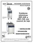
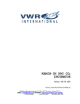
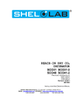
AIR JACKETED CO2 INCUBATORS SCO5A SCO5A-2 SCO10A SCO10A-2 Previously designated as 5215 5215-2 5230 5230-2 INSTALLATION AND OPERATION MANUAL Revised 11/2013 4861507 Sheldon Manufacturing Inc. P.O. Box 627 Cornelius, Oregon 97113 EMAIL: [email protected] INTERNET: http://www.Shellab.com/~Shellab 1-800-322-4897 (503) 640-3000 FAX (503) 640-1366 TABLE OF CONTENTS SECTION 1.0 RECEIVING AND INSPECTION SECTION 2.0 INSTALLATION SECTION 3.0 GRAPHIC SYMBOL SECTION 4.0 CONTROLS OVERVIEW SECTION 5.0 OPERATION SECTION 6.0 CALABRATION AND READING A FYRITE SECTION 7.0 MAINTENANCE SECTION 8.0 HEPA C02 FILTER SECTION 8.0 TROUBLESHOOTING SECTION 9.0 PARTS LIST UNIT SPECIFICATIONS SCHEMATICS These units are TUV CUE listed as air jacketed CO2 incubators for professional, industrial, or educational use where the preparation or testing of materials is done at approximately atmospheric pressure and no flammable, volatile, or combustible materials are being heated. These units have been tested to the following requirements: CAN/CSA C22.2 No. 61010-1:2012 CAN/CSA C22.2 No. 61010-2-010 + R:2009 UL 61010-1:2004 + R:2005-07 + R:2008-10 UL 61010A-2-010:2002 UL 61010-1:2012 EN 61010-1:2010 EN 61010-2-010:2003 IEC 61010-1:2010 IEC 61010-2-010:2003 2 Section RECEIVING AND INSPECTION 1 Your satisfaction and safety require a complete understanding of this unit. Read the instructions thoroughly and be sure all operators are given adequate training before attempting to put the unit in use. NOTE: This equipment must be used only for its intended application; any alterations or modifications will void your warranty. 1.1 Inspection: The carrier, when accepting shipment, also accepts responsibility for safe delivery and is liable for loss or damage. On delivery, inspect for visible exterior damage, note and describe on the freight bill any damage found, and enter your claim on the form supplied by the carrier. 1.2 Inspect for concealed loss or damage on the unit itself, both interior and exterior. If any, the carrier will arrange for official inspection to substantiate your claim. 1.3 Return Shipment: Save the shipping crate until you are sure all is well. Never ship anything back inside the chamber. If for any reason you must return the unit, contact your service representative for authorization and supply the data plate information. Please see the manual cover for information on where to contact Customer Service. 1.4 Accessories: Verify that your accessory kit is complete. The SCO5A (5215) and SCO5A-2 and (5215-2) are equipped with 3 shelves, supply hose kit, 4 leveling feet and pan. The SCO10A (5230) and SCO10A-2 (5230-2) are equipped with 6 shelves, supply hose kit, 4 leveling feet and 2 pans. Check all packaging materials before discarding. 3 Section INSTALLATION 2 Local city, county, or other ordinances may govern the use of this equipment. If you have any questions about local requirements, please contact the appropriate local agency. Installation may be performed by the end user. Under normal circumstances this unit is intended for use indoors, at room temperatures between 5 and 35C, at no greater than 80% Relative Humidity (at 25) and with a supply voltage that does not vary by more than 10%. The unit’s technical and environmental specifications includes: altitude not exceeding 2000 m operating and Pollution Degree of 2. Customer service should be contacted for operating conditions outside of these limits. 2.1 Power Source: The unit power requirements are listed on the data plate. PLUG THE UNIT INTO A PROPERLY GROUNDED AND RATED RECEPTACLE OF THE CORRECT STYLE. A separate circuit is recommended for this unit to prevent loss of product due to overloading or circuit failures caused by other equipment. The power supply must be properly grounded (earthed) and correctly sized to match the unit nameplate rating. The supply voltage must match the nameplate voltage within +/- 10%. The US market units are designed for 110 volts @ 50/60 Hz, 6.0 Amps. The EU market units are designed for 220 volts @ 50/60 Hz, 3.0 Amps. If supplied with a detachable cord set, plug the female end into the inlet on the unit and the male plug into the supply. Assure that units requiring fuses have them installed. The fuse is a T type, 10 Amp for 110 vol units, 6.3 Amp for 220 volt units. This fuse may be at the inlet or a part of the cord set male plug. The unit must be located to easily allow for it to be unplugged or disconnected. 2.2 Location: In selecting a location, consider all conditions, which might affect performance, such as heat from radiators, ovens, autoclaves, etc. Avoid direct sun, fast-moving air currents, heating/cooling ducts and high-traffic areas. To ensure air circulation around the unit, allow a minimum of 10cm (4”) between the unit and walls or partitions which might obstruct free airflow. 2.3 Lifting / Handling: These units are heavy and care should be taken to use appropriate lifting devices that are sufficiently rated for these loads. Units should only be lifted from their bottom surfaces. Doors, handles and knobs are not adequate for lifting or stabilization. The units should be completely restrained from tipping during lifting and transport. All moving parts, such as shelves and trays should be removed and doors need to be positively locked in the closed position during transfer to prevent shifting and damage. 2.4 Leveling: The unit must sit level and solidly. Leveling feet are supplied and must be installed in the four holes in the bottom corners of the unit. With the feet installed and the unit standing upright, each foot can be raised by turning it in a counterclockwise direction. Adjust the foot at each corner until the unit stands level and solid without rocking. If the unit is to be moved, turn the leveling feet all the way clockwise to prevent damage while moving. 2.5 Cleaning: The unit chamber was cleaned with a decontaminant at the factory, but it should be cleaned and disinfected prior to use. Operating conditions and appropriate protocol will determine the correct procedure for decontamination. A typical decontamination procedure that is adequate for many situations is described below, as are certain steps that will help reduce the likelihood of contamination and the necessity of decontamination. Whatever process is appropriate, it needs to be done on a regularly scheduled basis. Depending on usage and protocol, this may be monthly, quarterly or otherwise. Regardless of the decontamination procedure used, certain precautions will need to be taken: A. Always disconnect the unit from the electrical service when cleaning. 4 Assure all volatile or flammable cleaners are evaporated and dry before reconnecting the unit to the power supply. B. Special care should be taken when cleaning around sensing heads to Prevent damage. (See figure 1) Figure 1 C. Do not use chlorine-based bleaches or abrasive cleaners. These will modify the stainless steel interior finish. DO NOT USE hard tools such as metal wire brushes or steel wool. Use non-abrasive cleaners and soft tools such as plastic brushes. (See 7.1–A) D. Use only DISTILLED water in the humidity pan. DO NOT USE de-ionized water due to its reactivity with metal components. TYPICAL DECONTAMINATION PROCEDURE 1. Remove the humidity pan every week and autoclave, or wash with soap and water then disinfect with 70% alcohol solution diluted with distilled water. Replace in the incubator with fresh, DISTILLED water. 2. Flush the sample port tubing with 70% alcohol solution. Replace any discolored lines. 3. Clean and disinfect the liner gaskets. Clean and disinfect all mounting grooves for the door gaskets. 4. Remove all shelves, shelf supports, shelf standards and slides. Autoclave, or wash and disinfect as described in item 1. 5. Wash and disinfect all interior surfaces. 6. Give special attention to cleaning and disinfecting all access ports, shaft holes, electrical pass-through, and any other passages into the chamber. 7. Replace all HEPA (Patent No. 6,333,004) and CO2 filters every six months or when noticeably dirty on the upstream side. CO 2 filters are located in the shadow box just behind the GAS IN fitting and on CO2 sample line. Hepa filter is located on the top air duct inside the chamber. OPERATION FOR MINIMIZING CONTAMINATION 1. Keep the outside of the incubator, including the air in the laboratory, as clean as possible. This is particularly important for units placed directly on the floor. Do not place incubators near doors, air vents or other areas of high air movement or traffic. 2. The floor around the unit needs to be clean. Units that are placed on the floor should be mounted higher – typically on a caster platform – for ease of moving the unit during cleaning and access to the back of the unit. 3. Minimize the number of times access is made to the chamber during normal operation. 4. Do not depend on the use of antibiotics to maintain uncontaminated conditions, as this is an inadequate technique for sterilization. Preferably use aseptic techniques as described above for maintaining sterile conditions in the incubator. 5 2.6 Place shelves in chamber as desired. 6 Section GRAPHIC SYMBOLS 3 Your CO2 incubator is provided with a display of graphic symbols on the control panel, which are designed to help identify the use and function of the adjustable components. 1. Indicates that you should consult your manual for further description and discussion of a control or user item. 2. Indicates “Temperature” 3. Indicates “Over Temperature” 4. C Indicates “Degrees Centigrade” 5. Indicates “AC Power” 6. Indicates “Manual Adjustment” 7. Indicates “Gas” (CO2 pressurized gas for this unit) 8. Indicates “Potential Shock Hazard” behind partition 9. Indicates “Earth Ground” 10. 11. CO2 Indicates “Carbon Dioxide” Indicates “Unit should be recycled” (Not disposed of in land-fill) 7 Section CONTROL PANEL OVERVIEW (See Figure 1) 4 Figure 1 All controls are located on the front panel. Units with a detachable cord have a fused inlet located at the top rear of the incubator. This inlet has a recessed male plug, fuse and an EMI filtering system designed to filter out electrical interference. This inlet also prevents any internally generated interference from feeding out to the power grid. 4.1 Power Switch: The I/O (ON/OFF) switch controls all of the power for the incubator and must be in the I/ON position before any systems are operational. Both temperature and CO2 displays will illuminate when the power switch is in the ON position. 4.2 Safety Activated Light: This pilot lamp is on whenever the Over Temperature Safety thermostat has been activated and taken control of the heating element. During normal operating conditions this indicator should never be on. 4.3 Temperature Control: This controller is marked C and indicates the actual temperature within the chamber to .1C. The UP/DOWN buttons are used for imputing the set point, calibrating the display, and muting or unmuting the audible alarm. The HIGH and LOW alarm indicators will light whenever there is an alarm condition associated with the temperature within the chamber. The MUTE indicator will light whenever the audible alarm has been deactivated. 4.4 CO2 Control: This controller is marked %CO2 and indicates the %CO2 content within the chamber to .1%. The UP/DOWN buttons are used for to input the set point, calibrating the display, and muting or unmuting the audible alarm. The HIGH and LOW alarm indicators will light whenever there is an alarm condition associated with the CO2% within the chamber. The MUTE indicator will light whenever the audible alarm has been deactivated. The CO2 injecting light will illuminate whenever the controller is injecting CO2 into the chamber. 4.5 Over Temperature Safety Control (OTP): This is a hydraulic thermostat that is wired between the Main Temperature Controller and the heating element and functions as an override control. If at any time the Temperature Control fails in the ON position, and the temperature in the incubator rises above its set point, the OTP is activated and maintains temperature at its own set point. Note that the HEATING indicator will continue to function under the control of the Over Temperature Safety. 4.6 CO2 Sample Chamber: This is located in the upper front corner of the right side of the incubator. A sample can be drawn to measure the CO2 content in the chamber at this port. Muting Audible Alarms: The audible alarms can be muted for a single alarm occurrence by pressing and holding down EITHER the UP or DOWN button for several seconds until the alarm mutes. There is a built in delay of approximately 15 minutes on the occurrence of a LOW alarm. This time delay prevents the audible alarm from activating when not needed. 8 Section OPERATION 5.1 5.2 5.3 5.4 5.5 5.6 5.7 5 Check power supply against unit serial plate; they must match. Be certain that the fuse is installed in the power inlet of the unit. Plug service cord into the electrical outlet. Push power switch to the ON position, and turn the High Limit Thermostat to its maximum position, clockwise. Temperatures must be set before CO2 connection and adjustments are made. Setting the Temperature: Inputting the set point on the controls is a very easy process. A. Push and release either the UP or DOWN button and the digital display will start to blink from bright to dim. B. While the display is blinking it will be showing the set point which can be changed using the UP or DOWN buttons. C. If no buttons are pressed within five (5) seconds the blinking will stop and the display will revert to showing the process or actual parameter within the incubator chamber. Calibrating the Controls: A. Push and hold both the UP and DOWN buttons until the decimal points in the display begin to blink. B. While the decimal points are blinking the UP and DOWN buttons can be used to adjust the display to match the actual condition in the incubator chamber. C. If no buttons are pressed within five (5) seconds the blinking will stop and the display will revert to showing the process or actual parameter within the incubator chamber. Set the CO2 Controls: Inputting the set point on any of the controls is a very easy operation. A. Push and release either the UP or DOWN button and the digital display will start to blink from bright to dim. B. While the display is blinking it will be showing the set point which can be changed using the UP or DOWN buttons. C. If no buttons are pressed within (5) seconds the blinking will stop and the display will revert to showing the process or actual parameter within the incubator chamber. Set Over Temperature Thermostat: As mentioned in step previously, the Over temperature Thermostat should be initially set to its maximum position (turn clockwise until it stops) to allow the unit to stabilize. Once the incubator is stable at the desired set point, turn the thermostat counterclockwise until the OVERTEMP ACTIVATED light turns on. Next, turn the Thermostat clockwise just until the light turns off. Then turn the Thermostat clockwise again, about 1/16 of an inch. This will set the Over temperature Thermostat at approximately 1C above Main Temperature set point. Humidification: Humidification of the unit is achieved by evaporation of water from the humidity pan placed in the bottom of the incubator. By filling this stainless steel reservoir pan with DISTILLED WATER ONLY and allowing this water supply to heat and evaporate, near saturation humidity is achieved. Do not use plastic, glass or other metals. Only 300 series stainless metals are acceptable for this reservoir pan. Do not use corrosive chemicals including copper sulfate or chlorine in the pan or chamber as damage may occur. Use Distilled Water Only. DO NOT USE DEIONIZED WATER! Use of disinfecting chemicals in the chamber can change the surface tension of the reservoir water thus preventing evaporation and proper humidification of the chamber. Water in the pan 9 5.8 should be changed and the pan cleaned at least once a week to help control contamination and to maintain proper surface tension. CO2 Supply System and Control System: The CO2 system is rated for input pressures between 5 to 40 PSI which should never be exceeded at any time Humidity Pan PLUMBING DIAGRAM (figure 2) A. B. C. D. The CO2 inlet fitting is located at the back of the unit near the top (see Figure 2). It is marked CO2 TO CHAMBER. A supply hose with in-line CO2 filter (supplied with your accessories) connects from the fitting to a CO2 tank regulator. It is highly recommended that a good quality 0-60 PSI output range DUAL STAGE pressure regulator be used on the CO2 tank. The dual stage regulator will have two pressure gauges. The high pressure gauge (0-4000 PSI) will indicate the pressure within the tank. The low pressure gauge (0-60 PSI) will indicate the output pressure on the supply hose to the incubator. Do not use single stage regulators. They will not supply a stable pressure. Just because a regulator has two gauges does not mean that it is a dual stage regulator. Insure that you are using a dual stage CO2 regulator. It is normal for the high pressure gauge on your regulator to start out reading 800 to 1000 PSI with a full tank. The reading will drop to 500 to 800 PSI quickly and will stay there for most of the duration of the tank. At the end of use the pressure will drop quickly to zero to indicate that the tank is completely empty. Pure CO2 is in a liquid state in the tank, and a constant vapor pressure is generated in the tank above the liquid level. The CO2 is drawn off of the top as a gas. The same vapor pressure is maintained as long as any liquid is left in the tank. When the last of the liquid has evaporated into gas then the pressure will drop rapidly as the gas is drawn off. Only medical grade CO2 should be used in your incubator. The use of any lesser grade may damage your incubator and void your warranty. 10 E. F. G. The micro processor CO2 control system interprets the information from the CO2 sensor, displays the CO2 concentration directly on the digital display, reads the CO2 set point and controls the percentage of CO2 in the incubator chamber. The CO2 sensors operate under the principal that a certain frequency of infrared light is absorbed by CO2. The more CO2 is present the more light is absorbed. Advantages to this system are that it is only sensitive to CO2, so its accuracy is consistent no matter what the conditions, temperature and RH) are in the incubator. CO2 sensors are factory calibrated and under normal circumstances need no calibration in the field. It is recommended that the accuracy of the CO2 control system be monitored. By measuring the actual CO2 concentration on a weekly basis using a Fyrite or other measuring device. This should be done when the chamber has not been disturbed for an extended period of time i.e. after the weekend, or first thing on Monday morning. 11 Section FYRITE CO2 CHECKING 6 A Bacharach FYRITE CO Gas Analyzer is recommended to measure CO concentrations in the incubator chamber. This test instrument is not supplied with the incubator but is readily available from your dealer. Follow the instructions provided with each Fyrite instrument carefully to insure correct and accurate readings. Your incubator has a chamber sampling port, marked as such, at the top right side of the body. 1. Press button on top of Fyrite canister to release CO2 concentration. Tip canister to the side to ensure all fluid is released from top of canister. 2. Loosen screw on slide scale and align top of fluid with zero on the scale. Tighten screw. 3. Connect hose and aspirator bulb to unit being tested. The sample port for connection is located on the control panel. 4. Place the hose -sampling cap directly over the plunger valve on top of canister and depress firmly. 5. With button depressed, squeeze bulb 27 times. On the last squeeze and with bulb still deflated, release hose from button. 6. Turn Fyrite canister upside down 3 times, each time allowing all fluid to flow to the opposite end of the canister. 7. Tip canister to the 45-degree position to ensure all fluid has been released from top of canister. 8. Read CO2 concentration in %. NOTE: Your Fyrite indicator will come with a complete set of detailed instructions, which should be followed carefully. The fluid used inside this Fyrite instrument is poisonous and corrosive and must not be taken internally. In the event of a spill or accidental body contact with the Fyrite fluid, follow the instructions on the refill bottle carefully. 12 Section MAINTENANCE 7 NOTE: Prior to any maintenance or service on the unit, disconnect service cord from the power supply. 7.1 Cleaning: Disinfect the incubator interior on a regular basis. To prepare the incubator for cleaning remove the shelves and shelf slides. These stainless steel parts are autoclavable. A. First clean removed parts and interior with soap and water. To decontaminate use a disinfectant that is suitable for your application. DO NOT USE chlorine-based bleaches or abrasives, as this will damage the stainless steel interior. DO NOT USE spray cleaners that might leak through openings and cracks and get on electrical parts or that may contain solvents that will harm the coatings. WARNING: Never clean the unit with alcohol or flammable cleaners with the unit connected to the electrical supply. Always disconnect the unit from the electrical service when cleaning and assure all volatile of flammable cleaners are evaporated and dry before reattaching the unit to the power supply. B. When washing the interior, handle the gasket carefully so as not to impair the positive seal. 7.2 Check the CO2 supply periodically; do not let it run out. Automatic tank switches and "empty tank" alarms are available from your dealer. 7.3 Periodically check CO2 supply lines and connections for leaks. Use a liquid-soap solution to detect leaks and look for bubbles. 7.4 Keep the CO2 flow system free of impurities. Erratic CO2 control is usually traceable to the CO2 pressure regulator on the tank, impurities in the tank, or impurities trapped in the solenoid valve. Replace HEPA and CO2 filters when noticeably dirty on the upstream side or every six (6) months. There is a CO2 filter connected to the GAS-IN line inside the unit and accessible through the top and one attached to the supply hose kit. 7.5 If the incubator is turned off for an extended period of time, clean and disinfect. The unit can be reactivated. Simply turn it on and allow 24 hours for recovery. NO adjustments are necessary. If the unit is shut down deliberately for storage disconnect the gas and power supply. 7.6 There is no maintenance required on the electrical components. If the incubator fails to operate as specified. See Troubleshooting Section before calling for service. 13 Section HEPA CO2 FILTER 8 The CO2 Incubator design features a HEPA filtration system with a patented copper housing. (Patent Number 6,333,004) As the chamber air is drawn through the filter system, airborne microbes and isolated particulates are not only removed from the air, but destroyed as well. It is through copper oxidation that the contaminants are actually killed. The HEPA filter is easily replaced without the need of any tools and has an efficiency rating of 99.97% at 0.3 microns. The Hepa filter attaches to a fixed coupling ring with a direct “nap-in” action. Push straight up to the coupling ring to connect. Pull the filter straight down to disengage. Replacement Hepa filters is available from Sheldon Mfg., Inc. Part Number 2800517. Install the HEPA Filter onto the duct prior to installing the duct in the unit. WARNING: Ensure that when installing the duct to ensure that the duct is not touching the C02 sensor head as this may cause erroneous readings.2800517. 14 Section TROUBLESHOOTING 9 Always make a visual inspection of the incubator and control console when troubleshooting. Look for loose or disconnected wires or tubing which may be the source of the problem. The incubator is designed so that no internal electrical servicing should be required under normal conditions. If electrical servicing is necessary, qualified service personnel should perform it only. For information on where to reach technical service please see the manual cover. FOR PERSONAL SAFETY, ALWAYS DISCONNECT THE POWER BEFORE SERVICING. TEMPERATURE Temperature too high 1/ Controller set too high. 2/ Controller failed on – call Customer Service. Display reads "HI" Probe is unplugged, is broken or wires to sensor is broken. Temperature too low 1/ Over temperature too low. 2/ Controller set too low. 3/ Unit not recovered from door opening – wait for display to stop changing. 4/ Unit not recovered from power failure or being turned off. Display reads "LO" Shorted Sensor. Unit will not heat up at all 1/ Do all controller functions work? 2/ Is the Over temperature Thermostat set high enough? – For diagnostics, should be fully clockwise with the pilot light never on. Chamber temperature unstable 1/ Is ambient room temperature radically changing – either door opening or room airflow from heaters or air conditioning? – Stabilize ambient conditions. 2/ Electrical noise – remove nearby sources of RFI including motors, arcing relays or radio transmitters. Display and reference thermometer don’t match Out of calibration. Can't adjust set points or calibration 1/ turn entire unit off and on to reset. 2/ if repeatedly happens, call Customer Service. CO2 LEVEL Overshoots set point but stabilizes display and Fyrite match 1/ Internal fan not running or fan fell off. 2/ Plugged Hepa Filter. Overshoots set point and continues to rise - display and Fyrite match Debris in solenoid causing it to leak continuously Rises very slowly 1/ Filter overly dirty or partially plugged 2/ Hose kinked or leaking 3/ CO2 tank regulator set too low. 4/ CO2 tank near empty Never rises 1/ CO2 filter plugged 2/ CO2hose blockage 3/ CO2tank empty 4/ Set point is at 0.0 and has not been reset. 5/ CO2tank regulator not on Display and Fyrite reading do not match 1/ Old Fyrite fluid. 2/ Out of calibration. Unstable display 1/ Confirm that fan is working 2/ Magnetic field interference 3/ Electronic problem with CO2sensor, interface or controller 4/ Top of unit exposed to cold air drafts 5/ Incubator too heavily loaded Feeding continuously or abnormally high CO2 usage 1/ Do decay test: if more than 1% decay in an hour, check for leak : door gasket tightness, motor inlet to chamber, sensor and probe inlet to chamber 2/ Door being opened too often Won’t hold calibration – Fyrite reading varies but display stable 1/ Atmospheric pressure fluctuations 2/ Top of unit exposed to cold air drafts 3/ Unit being operated without shadow box cover in place 4/ Condensation collecting on CO2sensor 5/ CO2sensor or interface failure 6/ Unit incorrectly calibrated. 7/ Taking Fyrite reading too soon after the door has been opened 8/ Air leak around CO2sensor mounting plate MECHANICAL Door not sealing 1/ check physical condition of gasket. 2/ Confirm that door latch pulls door in tightly. 3/ Assure that gasket is in original location. Motor doesn't move 1/ if shaft spins freely: check connections to motor and check voltage to motor; 2/ if shaft rubs or is frozen, relieve binding and retest Motor makes noise 16 1/ Make sure that the fan or blower wheel is not contacting its housing. Adjust the motor mounting bracket position to re-center the fan or blower wheel, if necessary. 2/ Check the fan or blower wheel for damage or out of balance condition. Replace the fan or blower wheel if it is damaged or out of balance. 3/ Turn the motor shaft to make sure that it spins freely. If it binds or the bearings make a rubbing or scrapping sound then replace the motor. Solenoid valve buzzing After removing solenoid clean with alcohol for carbon build-up then blow out. Check valve seat or channels for contamination. Check CO2filter and/or grade of CO2 used. If seat is worn, replace. OTHER Controller on at all times - "locked-up" 1/ turn unit off and on to reset. 2/ if cannot change any condition on the front panel, call Customer Service. Front panel displays are all off Make sure unit is plugged in. Unit will not turn on 1/ Check wall power source. 2/ Check fuse/circuit breaker on unit or in wall. Contamination in chamber 1/ see cleaning procedure in Maintenance Section. 2/ develop and follow Standard operating procedure for specific application; include definition of cleaning technique and maintenance schedule. 17 Section 10 PARTS LIST Description 115V 220V 4 TO 20mA BOARD 1750667 1750667 Chamber Gasket, 8 feet 3450546 3450546 Circulating Fan 4880564 4880563 CO2 Display Board 1750660 1750660 CO2 Fan Motor 4880508 4880507 CO2 Filter 2800525 2800525 Door Heater 2350550 2350550 Door Switch 7850578 7850578 Element 9570902 9570903 Fuse, 6.3 amp 250v 3300516 3300515 Glass Door Assembly 9521141 9521141 HEPA Filter 2800517 2800517 IR Transmitter 8320510 8320510 LED Board 1750742 1750742 Multi-Channel Main Board 1750738 1750738 On/Off Switch 7850532 7850532 Over temperature Thermostat 1750862 1750862 Pilot Light, Red 4650553 4650553 Power Cord 1800510 1800500 Power Supply 6750507 6750507 Shelf 5121525 5121525 Solenoid Valve 8600528 8600529 Temperature Display Board 1750714 1750714 Recorder Jack 6900522 6900522 18 UNIT SPECIFICATIONS Weight Shipping Net SCO5A (5212) 195 134 SCO5A-2 (5212-2) 195 134 SCO10A (5230) 390 268 SCO10A-2 (5230-2) 390 268 Dimensions Exterior WxDxH (in.) Interior WxDxH (in.) SCO5A (5212) 26.75 X 27 X 38 20.5 X 20 X 23.25 SCO5A-2 (5212-2) 26.75 X 27 X 38 20.5 X 20 X 23.25 SCO10A (5230) 26.75 X 27 X 76 20.5 X 20 X 23.25 SCO10A-2 (5230-2) 26.75 X 27 X 76 20.5 X 20 X 23.25 Capacity Cubic Feet SCO5A (5212) 5 SCO5A-2 (5212-2) 5 SCO10A (5230) 10 SCO10A-2 (5230-2) 10 Temperature Range Control Uniformity CO2 Range SCO5A (5212) 5 above amb. to 60C +0.1C +0.25 @ 37C 0-20% SCO5A-2 (5212-2) 5 above amb. to 60C +0.1C +0.25 @ 37C 0-20% SCO10A (5230) 5 above amb. to 60C +0.1C +0.25 @ 37C 0-20% SCO10A-2 (5230-2) 5 above amb. to 60C +0.1C +0.25 @ 37C 0-20% 19 TO 20mA Board Conversions CO2 @ 4mA=0% CO2 Temperature @ 4mA=0° Celsius CO2 @ 20mA=20% CO2 Temperature @ 20mA=70° Celsius INCUBATOR ACCESSORIES 1. 2. 3. 4. 5. CO2 Tank Switch Fyrite CO2 Gas Analyzer In-Line Filter HEPA Filter Caster Platform Model Amp Voltage Hertz SCO5A (5212) 6.0 amp 110-120V~ 50/60 Hz SCO5A-2 (5212-2) 3.0 amp 208-240V~ 50/60 Hz SCO10A (5230) 6.0 amp 110-120V~ 50/60 Hz SCO10A-2 (5230-2) 3.0 amp 208-240V~ 50/60 Hz 20 WIRE DIAGRAM IEC FUSED FILTERED INLET 104179 115V - 10A - 3300516 230V - 6.3A - 3300515 BLK WHT WHT 115V - NOT USED 230V - 6.3A - 3300515 MAIN POWERSWITCH 7850532 BLK AIR JACKET FAN BLK BLK WHT WHT BLK 115V - 100909 230V - 103328 CO2 HEATER - 6W 115V - 210002 230V - 210001 BLK WHT 200021 BLK 18G WHT 18G MAIN PROBE 6750507 DOOR PROBE 1750667 12VDC POWER SUPPLY RING PROBE BUSS BUSS MAINPROBE 1750714 TEMPDISP 37.0 1750660 CO2DISP 5.0 GROUND LINE 2 LINE 1 LOAD 1 4 LOOP MAIN BOARD LOAD 2 IRPROBE 8320510 1750738 LOAD 3 DOORPROBE LOAD 4 CO 2 RING PROBE 4-20 SL LOGO LIGHT 1750742 BLK WHT BRN YEL WHT ORN RED 1 8000542 OTPSAFETY 4 WHT HT 2 1750813 8000542 YEL 200022 1 4 2 BLK HT MAIN ELEMENT SEEPARTSLIST 200021 200021 FOR 230V ELEMENTS ARE WIRED AS SHOWN FOR 115V ELEMENTS ARE WIRED IN PARALLEL DOOR HEATERS 4x103068 RING HEATER 4x103068 0.47f / 250v CAP 0900503 SV DOOR SW X100022 WHT 115V - 8600528 230V - 8600529 WHT BLK 9851090 dlr6/3/09 CHAMBER FAN WHT 115V - 4880508 230V - 4880507 21