1
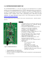
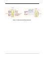
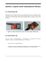
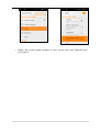
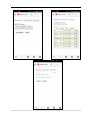
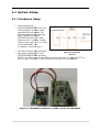
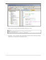
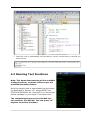
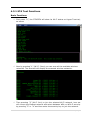
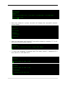
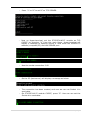
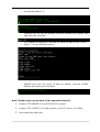
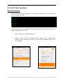
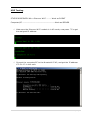
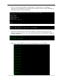
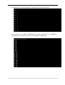
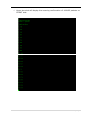
Discover Wi-Fi
User Manual
:
:
Release V1.3 Date 16th Aug 2013
i|P a g e
Revision history
Rev
Date
Description
By
1.0
20130614
Initial version
Huangyin
1.1
20130620
Modifying some instruction
Huangyin
1.2
20130805
Review and Modifications
Ankur Tomar
1.3
20130816
Review and Modifications
Ankur Tomar
ii | P a g e
Contents
Section 1 Introduction ......................................................................................... 1
1.1 Discover Wi-Fi ................................................................................................................................................. 1
1.2 STM32F4DISCOVERY Kit............................................................................................................................. 2
Section 2 Hardware Features ............................................................................ 3
2.1 Board Physical Dimensions ........................................................................................................................ 3
2.2 Board Electrical Characteristics ................................................................................................................ 3
2.3 Board Technical Description....................................................................................................................... 4
2.3.1 Block Description ....................................................................................................................................... 4
2.3.2 Wi-Fi Module - SN8200 ........................................................................................................................... 4
2.3.3 External Interface – Pin Detail ............................................................................................................. 6
Section 3 Quick Start (Standalone Mode) .................................................... 8
3.1 Powering ON .................................................................................................................................................... 8
3.2 First Start-up ................................................................................................................................................... 8
Section 4 Working with STM32F4DISCOVERY ........................................... 11
4.1 System Setup................................................................................................................................................ 12
4.1.1 Hardware Setup ....................................................................................................................................... 12
4.1.2 Turn the System Power ON ......................................................................................................... 13
4.2 Software Setup ............................................................................................................................................. 13
4.3 Running Test Functions ............................................................................................................................. 15
4.3.1 STA Test Functions ......................................................................................................................... 16
4.3.2 AP Test Functions ............................................................................................................................ 21
Section 5 Webserver Customization ............................................................. 28
Section 6 Safety Instructions .......................................................................... 29
iii | P a g e
Section 1 Introduction
The Discover Wi-Fi is a low power, self-contained, certified Wi-Fi network controller
module that provides simple serial-to-Wi-Fi connectivity to the internet and enables the
wireless connectivity to STM32F4DISCOVERY kit (a very flexible development kit based
on STM32F4 high performance microcontroller from STMicroelectronics). The Discover
Wi-Fi board connects to STM32F4DISCOVERY kit using serial host interface [UART OR
SPI]; it can also be used as a standalone Wi-Fi station or network controller. It can be
used to enable wireless connectivity to the simplest products with minimal engineering
resources.
1.1 Discover Wi-Fi
The Discover Wi-Fi board, a product designed by Embest, is based on Muratas’ SN8200
Wi-Fi Network Controller module. The board designed provides an easier connection to
the STM32F4 Discovery kit and supports more overall software features through UART.
Software demos are provided, including EZ Web Wizard solution, to help the users to
give quick and easy transition to wireless connectivity.
Board Features:
•
•
•
•
•
•
•
•
•
•
2.4GHz IEEE 802.11b/g/n
Support AP/STA Dual mode
Built-in TCP/IP Stack, HTTP, DHCP, DNS,
and Web Server
Support WPA/WPA2 PSK security
Wi-Fi chipset: Broadcom BCM43362
MCU: ST Microelectronics STM32 ARM Cortex-M3
Host Interface: UART, SPI Interface & Standalone
Other Interface: GPIO, ADC, DAC, I2C
JTAG Interface for Debugging
Power Options
o 5V Power Jack
o Mini USB Plug
Figure 1-1 Discover Wi-Fi
1|P a g e
1.2 STM32F4DISCOVERY Kit
The STM32F4DISCOVERY is a low-cost and easy-to-use development kit to quickly
evaluate and start a development with an STM32F4 high-performance microcontroller.
It is based on an STM32F407VGT6 and includes an ST-LINK/V2 embedded debug tool
interface, ST MEMS digital accelerometer, ST MEMS digital microphone, audio DAC with
integrated class D speaker driver, LEDs, pushbuttons and a USB OTG micro-AB
connector. For more information please refer to the STMicroelectronics official URL:
www.st.com/stm32f4-discovery .
You can purchase this kit from elment14, Order Codes: Farnell/element14 - 2009276, Newark 87T3791
Features:
STM32F407VGT6 microcontroller featuring 32bit ARM Cortex-M4F core, 1 MB Flash, 192 KB
RAM in an LQFP100 package
• On-board ST-LINK/V2 with selection mode
switch to use the kit as a standalone
STLINK/V2 (with SWD connector for
programming and debugging)
• Board power supply: through USB bus or from
an external 5 V supply voltage
• External application power supply: 3V & 5V
• LIS302DL, ST MEMS motion sensor, 3-axis
digital output accelerometer
• MP45DT02, ST MEMS audio sensor, omnidirectional digital microphone
• CS43L22, audio DAC with integrated class D
speaker driver
• Eight LEDs:
o LD1 (red/green) for USB
communication
o LD2 (red) for 3.3 V power
o 4 user LEDs; LD3 (orange), LD4
Figure 1-2 STM32F4DISCOVERY Kit
(green), LD5 (red) and LD6 (blue)
o 2 USB OTG LEDs LD7 (green) VBus and
LD8 (red) over-current
• Two push buttons (user and reset)
• USB OTG FS with micro-AB connector
• Extension header for all LQFP100 I/Os for quick connection to prototyping board
and easy probing.
•
2|P a g e
Section 2 Hardware Features
2.1 Board Physical Dimensions
Figure 2-1
2
DISCOVER WI-FI PCB
•
•
•
Size: 69mm*44mm
Board layer: 4
Board thickness: 1.6mm
2.2 Board Electrical Characteristics
•
•
•
Power: 5V, 2A; or Mini-USB
Mini
power.
Operating Temperature:
Temperature 0~70 oC.
Power Consumption: around 2.5 W.
3|P a g e
2.3 Board Technical Description
Figure 2-2 Discover Wi-Fi Hardware
2.3.1 Block Description
•
Wi-Fi Module: SN8200 Wi-Fi module
•
Power Section (J1, J4): The board is powered by Mini-USB or 5V, 2A DC.
•
Switch and LEDs: One reset switch and two signal LEDs.
•
External Interface
o
JTAG interface (J3): Standard 20 pin interface, used for Module Firmware Loading.
o
User interface (J6): external interface for users.
2.3.2 Wi-Fi Module - SN8200
Features
•
2.4GHz IEEE 802.11b/g/n Radio
•
Host Interfaces: UART & SPI
Technology
•
Other Interfaces: ADC, DAC, I2C,
•
Wi-Fi Chip - Broadcom BCM43362
•
MCU - STM32 ARM Cortex-M3
•
Dimension: 30.5 x 19.4 x 2.8 mm
•
Package: LGA
•
ROHS Compliant
•
On-Board Antenna
•
FCC/IC certified, CE compliant
•
Max Receive Sensitivity: -96dbm @ b
•
PN 88-00151-00
mode/11Mbps
•
EVK/SDK P/N 88-00151-85
•
GPIO
•
Operating Temperature Range: -30ºC
to 85ºC
Transmit Power: +18 dBm
4|P a g e
Competitive Advantages
•
•
•
•
CE Certified
TCXO/XTAL that support extended product life
Wide Link Budget (up to 113 dB)
Easy software integration
o AP/STA dual mode
o Built-in Wi-Fi security support for WPA-PSK, WPA2-PSK
o Built-in TCP/IP stack
o Built-in DHCP, DNS
o Built-in HTTP server for AP mode
o Simple integration interface – Serial Network Interface (SNIC) support
socket interface
SN8200 Block Diagram
Figure 2-4 SN8200 Diagram
5|P a g e
2.3.3 External Interface – Pin Detail
Table2-1 External Interface Pin Functions
J3
J6
PINS
Function
PINS
Function
1
VCC-MCU
2
VCC-MCU
3
SPI_MISO/JRTST
4
GND
5
JTMS
6
GND
7
JTCK
8
GND
9
-
10
GND
11
SPI_SCK/JTDO
12
GND
13
RST_N_SW
14
GND
15
-
16
GND
17
-
18
GND
19
-
20
GND
1
VCC-MCU
2
VCC-MCU
3
UART_RX
4
SPI1_MOSI
5
UART_TX
6
SPI1_SCK
7
UART_RTX
8
SPI1_NSS
9
UART_CTS
10
SPI1_MISO
11
GND
12
GND
13
LED-net
14
SPI3_SCK/JTDO
15
RST_N_SW
16
SPI3_MOSI/LED-ready
17
Interrupt
18
SPI3_MISO/JRTST
19
WAKER UP
20
SPI3_NSS/JTDI
6|P a g e
Figure 2-3 External Interface Schematic
7|P a g e
Section 3 Quick Start (Standalone Mode)
3.1 Powering ON
The Discover Wi-Fi board can be powered using 5V-2A DC power adapter OR Mini
USB power supply, please make an appropriate selection of your choice using
jumper J5; DC or USB. Once the board is powered ‘ON’, by default it will go into
AP mode.
Figure 3-1 Power Connection (Left: DC Power; Right: USB Power)
3.2 First Start-up
First we need a computer/laptop or Smartphone or equipment with Wi-Fi
capability. Here we are using Smartphone as an example.
Step1: Open your WLAN Settings
Step2: You’ll find the “Murata Wi-Fi wireless AP”, because the Discover WiFi module is running in AP mode by default. Now “Join” the network.
8|P a g e
Step3: Go to the mobile browser of your choice, and visit “SN8200.com”.
You’ll get it.
9|P a g e
10 | P a g e
Section 4 Working with
STM32F4DISCOVERY
Discover Wi-Fi module provides UART and SPI host interface, Embest has provided
no. of test code to help the end user to control the Discover Wi-Fi expansion
board from STM32F4DISCOVERY Kit using UART interface (for SPIs interfaces
users can develop their own solution using Murata SPI software solution, for more
information please refer to Discover Wi-Fi/SN8200 Reference Material/SNIC-SPI01-2B091.exe). Below is the list of developed main functions for UART solution:
0
Get Wi-Fi Status
1
Wi-Fi Scan
2
Join Wi-Fi
3
Get IP
4
TCP Client
5
TCP Server
6
Send From Stock
7
Disconnect Wi-Fi
8
AP ON/OFF
9
UDP Client
a
UDP Server
b
Wi-Fi OFF
c
Wi-Fi ON
m
Show Menu
q
Press 'q' to Quit
11 | P a g e
4.1 System Setup
4.1.1 Hardware Setup
First connect the
STM32F4DISCOVERY kit to the
Discover Wi-Fi
Fi module using
provided DuPont cables. For
this example we will be using
UART interface between
STM32F4 Discovery
iscovery kit and
Discover Wi-Fi
Fi module. Please
refer to the
he Figure 4-2
4 (or refer
to the schematic <WI<WI
FI_SN8200_schematic.pdf>).
We also need a Hyper-terminal
Hyper
Figure 4-1
1 Connection
connection between PC and
Diagram
STM32F4DISCOVERY kit using
RS232, for which we will use USB to serial converter (or you need TTL to
RS232 logic converter if USB to serial converter is not available).
Figure 4-2
2 Physical Connection (USB to serial not included)
12 | P a g e
Connect the USB end of the USB-RS232 converter to the computer/PC and
see if it's installed and detected as a COM port of computer/PC as below
(COMx is according to your computer/PC configuration, here it’s COM11):
Now setup a Hyper-terminal communication on your computer/PC using
below setting:
Port: COMx (accordingly)
Bits: 115200
Data bits: 8
Parity Check: none;
Stop: 1
Data flow control: none
Note: Recommended computer/PC configuration:
2.0GHz (or higher) of the CPU
512M RAM
USB interfaces
A serial interface
Windows XP and above operating system
Pre-installed KEILIDEv4.70, or please follow the below steps to install KEILIDE.
4.1.2 Turn the System Power ON
Turn the system power ON for the STM32F4DISCOVERY kit and Discover Wi-Fi
board.
•
•
STM32F4DISCOVERY Kit: Connect the MicroUSB cable between
STM32F4DISCOVERY Kit USB port (CN5) and computer/PC USB port.
Discover Wi-Fi Board: You can use either MiniUSB cable or 5V@ 2A DC to
power ON the Wi-Fi module, please refer to Section 3.1.
4.2 Software Setup
First open the Sample Project in KEIL MDK ARM IDE (location: Discover WiFi\Software\Discover wifi\Project\WiFi_Demo_V2.1_20130620\MDK-ARM).
Now build the project by clicking “Built” icon in IDE or by pressing “F7” function key.
13 | P a g e
Make sure the project is built successfully without any errors.
Download - after successful build, download the code into the board by clicking
“Download” icon and wait for download to finish.
14 | P a g e
Once the code is downloaded into the board it will be verified and you should see
below screen.
4.3 Running Test Functions
Note: This demo demonstrates all the available
testing functions, so please follow as per the
provided instruction below:
Once the sample code is downloaded into the board
(as described in Section 4.2), please RESET the
STM32F4DISCOVERY Kit. Upon REST you should see
bellow message on your Hyper-Terminal screen:
The compete testing process is divided into
two sections; STA and AP. You can press “m”
anytime to back to the Menu.
15 | P a g e
4.3.1 STA Test Functions
Basic Functions
First press ”0”, the STM32F4 will show its Wi-Fi status on Hyper-Terminal,
as below:
Now by pressing “1” (Wi-Fi- Scan) you can scan all the available wireless
networks. The terminal will display the scanned wireless networks.
Then pressing “2” (Wi-Fi Join) to join the selected Wi-Fi network, here we
will choose the Embest network and select between WPA or WPA 2 security
by pressing “2” or “4” and then enter the security key to join the network.
16 | P a g e
Once the network is joined, terminal will display the successful network
joined status.
Now you can again verify the Wi-Fi connection status by pressing “0”. It will
show the joined wireless network.
To know the assigned IP address and STA mode, press”3”, assigned IP in
this case IP is: 192.168.2.125
17 | P a g e
TCP Testing
STM32F4DISCOVERY Kit>>Discover Wi-Fi ------ Work as CLIENT
Computer/PC -------------------------------------------Work as SERVER
Connect your computer/PC to the same wireless network (Embest in this
case), and get your IP: 192.168.2.158
Now setup a TCP client on the STM32F4-WI-FI and connect to the TCP
server created on computer/PC. Please follow the below step to setup
SERVER and CLIENT.
o
On PC, first run the testserver application: testserver.exe. (location:
Discover Wi-Fi\Software)
18 | P a g e
o
Press ”1” on PC to set PC as TCP SERVER.
o
Now on Hyper-terminal, set the STM32F4-WI-FI module as TCP
CLIENT by pressing ”4” from the main Menu. Hyper-terminal will
display a message of opening Socket 4. Now enter the SERVER IP
address (computer/PC) and the SERVER port:
o
Now the socket connection if UP:
o
On the PC (test server) will display a message as below:
o
The connection has been created, and now we can use Socket 1 to
send data.
On STM32F4-Wi-Fi module CLIENT, press ”6”. Here we can set the
Socket 4 to send data:
o
19 | P a g e
o
Choose the default ”0”
o
128bytes will be sent as default, and the SERVER will display that
data has been received.
o
o
Let’s change the direction, SERVER will send the data to the CLIENT.
Press”2” on the SERVER window:
o
SERVER has sent 200 bytes of data as default, and the CLIENT
displays the receiving of the data.
Note: Similar steps can be done in the opposite direction.
1.
Create a TCP SERVER on the STM32 WI-FI module
2.
Create a TCP CLIENT on PC and connect to the TCP server on STM32
3.
Send data back and forth.
20 | P a g e
4.3.2 AP Test Functions
Basic AP Function
Once the Discover Wi-Fi module is in AP mode as default, but you can press
”8” to change its state.
It can be tested if AP is ON/OFF by using another Wi-Fi device, here we are
using Smartphone to do so:
o
Step1: Open your WLAN Settings
o
Step2: You’ll find the “Murata Wi-Fi wireless AP”, because the
Discover Wi-Fi module is running in AP mode by default. Now “Join”
the network.
21 | P a g e
o
Step3: Go to the mobile browser of your choice, and visit
SN8200.com”. You’ll get it
22 | P a g e
UDP Testing
STM32F4DISCOVERY Kit>>Discover Wi-Fi ------ Work as CLIENT
Computer/PC -------------------------------------------Work as SERVER
Make sure the Discover Wi-Fi module is in AP mode, now press ”3” to get
the assigned IP address:
Connect the computer/PC to the Murata Wi-Fi AP, and get the IP address:
172.31.0.3 in this case.
23 | P a g e
On PC, first run the testserver application: testserver.exe. (location:
Discover Wi-Fi\Software) and setup the computer/PC as a UDP SERVER by
selecting option 3 from the menu:
Setup the STM32F4 Wi-Fi as UDP CLIENT by selection 9 from the main
Menu on Hyper-terminal, you will be displayed with the SERVER IP address
and port number.
After that, the CLIENT will send 10 UDP packets to the SERVER:
24 | P a g e
The SERVER will acknowledge by displaying received as below:
Now press ”a” on CLIENT (STM32F4 Wi-Fi) side, and press ”4” on SERVER
(computer/PC) side to send 100 UDP packets to testclient.
25 | P a g e
Hyper-terminal will display the receving confirmation of 100UDP packets on
CLIENT side.
26 | P a g e
Once the tests are finished you can press 'q' to terminate the program and
the terminal will show as below:
27 | P a g e
Section 5 Webserver Customization
Figure 4-4 EZ Web Wizzard Solution
At the same time, developers can also develop their own firmware including
webserver contents based on Murata EZ Web Wizzard Solution, Murata EZ Web
Wizzard (EWW) software supports easy custom web-based control to save the
cost on additional host microcontroller. For more information please refer to
Murate URL below: http://www.murata-ws.com/sn8200.htm
28 | P a g e
Section 6 Safety Instructions
Please note that the Discover Wi-Fi board is supplied without any casing/box, all
the components are exposed. Therefore, extra precautions must be taken for ESD
(electrostatic discharge) to make sure that there is no static interference when
using this board. Appropriate ESD protections must be taken and wearing
electrostatic equipment is recommended such as wearing an anti-static wristband.
ESD damage can range from subtle performance degradation to complete device
failure. Precision IC's may be more susceptible to damage because of very small
parametric changes could cause the device to fail its defined specifications.
Warning:
This is a class B product, this product may cause radio interference in which case
users may be required to take adequate measures.
29 | P a g e