1
U17839EJ1V0X300.doc
June 2008
Supplement
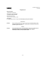
[Document Name]
ID78K0R-QB User’s Manual
[Document No., Date Published]
U17839EJ1V0UD00, June 2006
[Published Department]
NEC Electronics Corporation, Japan
[Description]
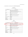
(1) <p.45> Modify Remark in chapter “5.3.3 Mixed display mode (Source Window)”
<Previous>
Remark:
When scrolling is performed using the cursor keys in the Mixed display mode,
excessive scrolling may occur. Also, scrolling down to the last line may not be
possible using the cursor keys.
<New>
Remark:
The disassemble section cannot be edited in the Source window even if
the Source window is set to the mixed display mode. Edit the
disassemble section in the Assemble window.
1/54
U17839EJ1V0X300.doc
(2) <p.46> Deletion of conversion symbol in “Table 5-5 Specifying symbols”
<Previous>
<New>
2/54
U17839EJ1V0X300.doc
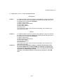
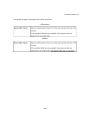
(3) <p.50> Modify Caution in chapter “(2) Software break”
<Previous>
Caution:
If a software break is set to the execution start address in order to re-execute
the code in the execution start address, the following events which are set to
the address are not generated. [IECUBE]
(1) Start of section trace
(2) Start of section measurement
(3) Trace delay trigger
(4) Event after execution
(5) Access event
To re-execute the code in the execution start address, use a break for the
event before execution.
<New>
Caution 1:
Caution 2:
If a software break is set to the execution start address in order to re-execute
the code in the execution start address, the following events which are set to
the address are not generated. [IECUBE]
(1) Start of section trace
(2) Start of section measurement
(3) Trace delay trigger
(4) Event after execution
(5) Access event
To re-execute the code in the execution start address, use a break for the
event before execution.
Do not overwrite programs in which a software break has been set to
the internal RAM area or external RAM area; otherwise, the break may
not occur normally. Even if the break occurs, the program before being
overwritten is automatically restored.
Therefore, use software breaks to set breaks to programs in the RAM
area.
3/54
U17839EJ1V0X300.doc
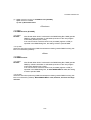
(4) <p.84> Changes in chapter “5.15 DMM Function [IECUBE]”
<p.84> Third line in remark
<p. 199> (3) Break When Write
<Previous>
<1><p.84>
5.15 DMM Function [IECUBE]
<2><p.84>
Remark:
After "Break When Write" is selected in the DMM Dialog Box, DMM (pseudo
DMM) by software simulation is selectable (execution of the user program
momentarily breaks upon a write).
If an area for which a real-time write is not permitted (register or SFR) is
specified in the DMM Dialog Box, the setting is fixed to pseudo DMM.
<3><p.199>
Select this item when performing DMM via software emulation (pseudo DMM function) (this
item is not selected by default).
<New>
<1><p.84>
5.15 DMM Function
<2><p.84>
Remark:
After "Break When Write" is selected in the DMM Dialog Box, DMM (pseudo
DMM) by software simulation is selectable (execution of the user program
momentarily breaks upon a write).
If an area for which a real-time write is not permitted (register or SFR) is
specified in the DMM Dialog Box, or when MINICUBE2 is used, the setting
is fixed to pseudo DMM.
<3><p.199>
Select this item when performing DMM via software emulation (pseudo DMM function) (this
item is not selected by default). When MINICUBE2 is used, however, this item is always
selected.
4/54
U17839EJ1V0X300.doc
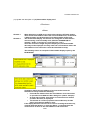
(5) <p.112> Modifiy Remark
<Previous>
Remark:
If the screen resolution is low (800 - 600, etc.), all the statuses may not be
displayed on the status bar.
<New>
Remark:
If the screen resolution is 800 ⋅ 600 or lower, some statuses are not
displayed.
With 800 ⋅ 600, for example, the enclosed area in the following figure will
not be displayed.
5/54
U17839EJ1V0X300.doc
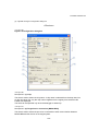
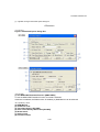
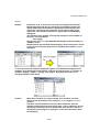
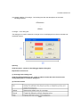
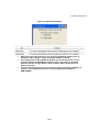
(6) <p.115> Change in Configuration dialog box
<Previous>
<1><p.115>
Figure 6-5 Configuration dialog box
<2><p.116>
Description in (1) Chip
This area is used to select the chip name. A chip name is selected from the drop-down list.
On the drop-down list, only the chip names registered to the registry from the device file
installer are displayed.
This area can be specified only when the debugger is started up.
<3><p.117>
Description in (6) Target Device Connection [MINICUBE2]
This area is used to select the port to be connected for serial communication between
MINICUBE2 and the device on the target system.
6/54
U17839EJ1V0X300.doc
The 1-wire mode (TOOL0) and 2-wire mode (TOOL0 + TOOL1) are supported as the
communication interface.
If the 2-wire mode (TOOL0 + TOOL1) is selected, (1) Use MINICUBE Extended Function
[MINICUBE2] in the Extended Option dialog box becomes selectable.
The type of port that can be selected depends on the device used.
This area can be specified only when the debugger is started up.
<4><p.118>
(8) Peripheral Break
<5><p.120>
Above (13) Function buttons
<6><p.120>
Below (13) Function buttons
<7><p.120>
Item number of (13) Function buttons
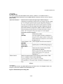
<New>
<1><p.115>
Figure 6-5 Configuration dialog box
7/54
U17839EJ1V0X300.doc
<2><p.116>
Description in (1) Chip
This area is used to select the chip name. A chip name is selected from the drop-down list.
On the drop-down list, only the chip names registered to the registry from the device file
installer are displayed. This area can be specified only when the debugger is started up.
(After the debugger is started, this area appears dimmed and the setting cannot be
changed.)
If a project file to which a different chip is specified is loaded after the debugger
startup, the chip name specified in the project file is ignored.
<3><p.117>
Description in (6) Target Device Connection [MINICUBE2]
This area is used to select the port to be connected for serial communication between
MINICUBE2 and the device on the target system.
The 1-wire mode (TOOL0) and 2-wire mode (TOOL0 + TOOL1) are supported as the
communication interface. The type of port that can be selected depends on the device used.
This area can be specified only when the debugger is started up.
If the 1-wire mode (TOOL0) is selected, the RRM function can be set to the 1-wire mode
(TOOL0) in the Extended Option dialog box. For details, refer to the descriptions of
Extended Option dialog box.
8/54
U17839EJ1V0X300.doc
<4><p.118>
(8) Peripheral Break
Caution: If the target device is the 78K0R/Ix3, the open break function is enabled by
selecting Category A.
The open break function is used to set to Hi-Z the timer pins, which control a
motor, so as to stop the motor safely if the motor control signal is not fed
back due to CPU stoppage (break) and the signal may have an adverse effect
on the motor.
The device and pins subject to manipulation by the open break function are
listed in the following table. When the open break function is used, the
motor stops upon a break and thus the program cannot be re-executed. In
such a case, reset the CPU.
<5><p.120>
Above (13) Function buttons
(13) Low-voltage Flash Rewriting [MINICUBE2]
This area is used to select whether to enable flash rewriting at 1.8 V or higher.
(Applicable to 78K0R/Kx3-L only)
<6><p.120>
Below (13) Function buttons
(14) Monitor Clock
This area is used to select whether to use the high frequency for the monitor program during
a break.
9/54
U17839EJ1V0X300.doc
<7><p.120>
Item number of (13) Function buttons
(15) Function buttons
10/54
U17839EJ1V0X300.doc
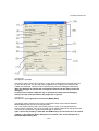
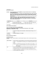
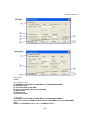
(7) <p.121> Change in Extended Option dialog box
<Previous>
<1><p.121>
Figure 6-6 Extended Option Dialog Box
<2><p.122>
(1) Use MINICUBE Extended Function [MINICUBE2]
To use the MINICUBE Extended Function, this area is selected.
If this item is selected, the RRM function is enabled, (2) RAM Monitor can be selected.
<3><p122 to p.124>
(2) RAM Monitor
(3) On Mouse Click:
(4) Trace Data Priority [IECUBE]
(5) Clear Trace Memory Before Run [IECUBE]
(6) Break Sound
(7) Verify Check
(8) Function buttons
11/54
U17839EJ1V0X300.doc
<4><p.122>
(2) RAM Monitor
This area is used to set about RAM monitor function. (Refer to "5.14 RRM Function".)
If (1) Use MINICUBE Extended Function [MINICUBE2] is selected, this area can be selected.
[MINICUBE2]
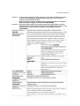
<New>
<1><p.121>
The IRAM option button (for [MINICUBE2] only) and items Clock, CKC Register Value, and
Frequency have been added to the RAM Monitor area.
Figure 6-6 Extended Option Dialog Box
12/54
U17839EJ1V0X300.doc
<2><p.122>
Deleted
<3><p.122 to p.124>
(1) RAM Monitor [IECUBE] and RAM Monitor And DMM [MINICUBE2]
(2) On Mouse Click:
(3) Trace Data Priority [IECUBE]
(4) Clear Trace Memory Before Run [IECUBE]
(5) Break Sound
(6) Verify Check
(7) Function buttons
<4><p.122>
(1) RAM Monitor [IECUBE] and RAM Monitor And DMM [MINICUBE2]
This area is used to set RAM monitor functions, and DMM functions (for MINICUBE2
only).
(Refer to "5.14 RRM Function" and “5.15 DMM Function”.)
13/54
U17839EJ1V0X300.doc
Caution 1: If the pseudo real-time monitor function is used while the Memory window
is open, the operability is degraded significantly (due to an excessive
amount of communication data).
When using the pseudo real-time monitor function, therefore, closing the
Memory window is highly recommended. [MINICUBE2]
Caution 2: The Clock option buttons are used to select the CPU operation clock for
RAM monitoring. This setting determines the communication speed, so the
CPU operation clock cannot be changed during RAM monitoring.
[MINICUBE2]
14/54
U17839EJ1V0X300.doc
(8) <p.133> Addition of cautions to “(1) Source Path” below Remark 3”
<Previous>
-
<New>
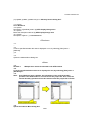
Caution 1:
Caution 2:
When a project file is open, the [Base:] setting specifies a folder to
which the project file has been loaded. Even if a load module file is
downloaded from another folder, the source file is therefore searched
for from the folder to which the project file has been loaded.
The following shows an example.
← Folder to which the project file has been
C:\TEST\
loaded
← Downloaded load module file
D:\TEST\TEST.LMF
Under such conditions, if source files with the same name exist under
both C:\TEST\ and D:\TEST and D:\TEST\TEST.LMF is downloaded, the
source file stored under C:\TEST\ is opened.
When a project file is not open and the source path has been set to the
text box, the source file is searched for from the folder set as the source
path even if a load module file is downloaded from a folder different
from the one set as the source path.
The following shows an example.
← Folder set as the source path
C:\TEST\
← Downloaded load module file
D:\TEST\TEST.LMF
Under such conditions, if source files with the same name exist under
both C:\TEST\ and D:\TEST and D:\TEST\TEST.LMF is downloaded, the
source file stored under C:\TEST\ is opened.
15/54
U17839EJ1V0X300.doc
(9) <p.139> Change description of [File name] in ”(1) Save file setting area”
<Previous>
Up to 257 characters string with an extension can be specified.
<New>
A string of up to 259 characters with a path name and an extension can be specified.
16/54
U17839EJ1V0X300.doc
(10) <p.140> Change description of [File name] in ”(1) Load file setting area”
<Previous>
Up to 257 characters string with an extension can be specified.
<New>
A string of up to 259 characters with a path name and an extension can be specified.
17/54
U17839EJ1V0X300.doc
(11) <p.142> Change descriptions of [File name] in ”(1) Load file setting area” and “(2) Load”
<Previous>
(1) Load file setting area
[File name] Up to 257 characters string with a extension can be specified.
(2) Load
Sets a load condition.
This setting is valid only if a file in the load module format is specified.
<New>
(1) Load file setting area
[File name] A string of up to 259 characters with a path name and an extension can be
specified.
(2) Load
Sets a load condition.
This setting is valid only when downloading a load module file.
(If an item other than “Load Module” is selected as a file type, the [Load] area appears
dimmed and the setting becomes invalid. Even if “Load Module” is selected as a file
type, the [Load] area setting is ignored if a file other than a load module file (such as a
hex file) is specified as a file type by directly typing it.)
18/54
U17839EJ1V0X300.doc
(12) <p.144> Change description of [File name] in “(1) Upload file setting area”
<Previous>
Up to 257 characters string with an extension can be specified.
<New>
A string of up to 259 characters with a path name and an extension can be specified.
19/54
U17839EJ1V0X300.doc
(13) <p.153> Add remark below the “Context menu table”
<Previous>
-
<New>
Remark 1:
When code that includes too many instructions in one line exists in the
Source window (cases such as one line being repeatedly executed),
step-wise execution of this one line takes time. As a result, processing
of step-wise execution may be aborted in mid-flow. If aborted, the
execution is suspended in the middle of the source line.
The following shows an example:
int i;
for(i = 0; i < 10000; i ++){}
In the above example, the for statement in the second line is intended to
repeat instruction processing 10,000 times. If such code is executed,
processing of step-wise execution may be aborted mid-flow.
This does not apply if the processing involves multiple lines. In the
above example, the following code can avoid the case.
int i;
for(i = 0; i < 10000; i ++){}
In this case, if step-wise execution is performed for the for statement in
the second line, the current PC line moves to "}" in the fourth line, stepwise execution of the fourth line is performed, and then the current PC
line moves again to the second line.
The number of instructions performed in one step-wise execution is
reduced, so step-wise execution processing is not aborted.
Remark 2:
When step-wise execution completes processing of the last prologue
("}") of the main function in the Source window, processing seems as if
it returns to the beginning of the main function.
Since the main function is called from the startup routine, the current
PC line moves to the startup routine after main function processing is
completed. If the PC is in the startup routine, the current PC line is
placed at the beginning of the main function in the Source window.
20/54
U17839EJ1V0X300.doc
(14) <p.154> Change description of [Find What] in “(1) condition specification area”
<Previous>
This area is used to specify the data to be searched. (Up to 256 character.)
<New>
This area is used to specify the data to be searched. (Up to 150 characters.).
21/54
U17839EJ1V0X300.doc
(15) <p.159> Add description of “(4) Disassemble display area”
<Previous>
-
<New>
Remark 1:
Remark 2:
When displaying an SFR access instruction while an SFR with another
name exists at the address where the accessed SFR exists, an SFR with
a different name may be displayed in the disassemble display area.
The disassemble display is a function for reaing data at each address
and converting it into assembly code. (With the ID78K0R-QB, for
example, "0x00" is read and it is converted into "nop".)
Since the instruction length may be multiple bytes, the disassemble
data may not be displayed correctly under the circumstances where the
start address of an instruction cannot be identified correctly.
The following shows an example of disassemble display output by the
ID78K0R-QB.
Conditions where the start address of an instruction cannot be
identified correctly include the following.
• If an address different from the start address of the instruction
is specified in the Address Move dialog box. (Above example)
• A range that includes areas where no instructions are written
(such as data area) is displayed.
• The window is scrolled up (toward lower addresses) for 500
bytes (equivalent to 0x200) or more.
If the display becomes incorrect as a result of scrolling the window up,
click the [Refresh] button, or select the [Move...] command from the
context menu to move to the start address of the instruction.
22/54
U17839EJ1V0X300.doc
(16) <p.154> Add remark to “Figure 6-23 Assemble Search Dialog Box” and description of
[Find What] in “(1) Search condition specification area”
<Previous>
This area is used to specify the data to be searched. (Up to 256 character.)
<New>
Remark:
Search cannot be performed during program execution. (The function
button appears dimmed.)
This area is used to specify the data to be searched. (Up to 150 characters.).
23/54
U17839EJ1V0X300.doc
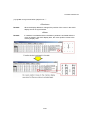
(17) <p.171> Change/Add Remark 1
<p.171> Change/Add remark above Figure 6.27
<p.173> Change/Add caution
<p.175> Change/Add remark below Context menu table
<Previous>
<p.171>
Remark 1:
If a local variable and a global variable exist with the same name, the local
variable takes priority.
<p.171>
Remark 2:
A maximum of 10,000 lines can be displayed in the Watch Window.
<p.173>
<p.175>
-
<New>
<p.171>
Remark 1:
Remark 2:
If a local variable and a global variable exist with the same name, the
local variable takes priority.
When a variable is referenced in the Watch window during program
execution, the data currently being changed may be displayed at the
timing of the variable change.
<p.171>
Remark 3:
Remark 4:
A maximum of 10,000 lines can be displayed in the Watch Window.
Multiple lines cannot be selected in the Watch Window.
<p.173>
Caution:
Even if Hex is selected for Radix in the Watch Default field in the
Debugger Option dialog box, the number of array variables is not
displayed in hexadecimal in the Watch window. (The following shows
examples when array “ary" is displayed.)
Desired display example:
← Hexadecimal
• ary [0x2]
← Hexadecimal
• ary[0x0]
← Hexadecimal
• ary[0x1]
Actual display example:
← Decimal
• ary [0x2]
← Hexadecimal
• ary[0x0]
• ary[0x1]
← Hexadecimal
24/54
U17839EJ1V0X300.doc
<p.175>
Remark:
If elements such as structures and arrays are registered in the Add
Watch dialog box and they are referenced in the Watch window, the
display with which each member is displayed and the display radix
setting are not saved in the project file. To save these items to the
project file, each member must also be registered in the Add Watch
dialog box.
The following is an example of saving the display for each member of
the array "a" shown below.
char a[2][2];
Register the array "a" in the Add Watch dialog box and then display its
members in the
Watch window; the following display appears. Even if this state is saved
in the project file and the project file is reloaded, the members are not
displayed.
To save the state with members displayed, register in the Add Watch dialog box the
members to be displayed. In this example, register not only the array "a", but also its
members "a[0][0]", "a[0][1]", "a[1][0]", and "a[1][1]". By taking this measure, the
following display can be saved.
Caution:
When Auto variables are used to display local variables, accurate
values cannot be displayed at a prologue (“{”) or epilogue (“}”) of a
function.
(The Auto variable addresses are the relative addresses from the
address pointed to by the stack pointer (SP), so their addresses are not
determined until the SP value is determined in the function. The SP is
manipulated via prologues or epilogues, so the accurate value cannot
be displayed.)
25/54
U17839EJ1V0X300.doc
(18) <p.183> Add caution to table “(1) Local variable display/variable value changing area”
<Previous>
-
<New>
Caution:
When Auto variables are used to display local variables, accurate
values cannot be displayed at a prologue (“{”) or epilogue (“}”) of a
function.
(The Auto variable addresses are the relative addresses from the
address pointed to by the stack pointer (SP), so their addresses are not
determined until the SP value is determined in the function. The SP is
manipulated via prologues or epilogues, so the accurate value cannot
be displayed.) Open the project file.
26/54
U17839EJ1V0X300.doc
(19) <p.189> Change remark below “(3) 0 1 2 3….”
<Previous>
Remark:
When the display address is changed, the position of the cursor in the ASCII
display area is not synchronized.
<New>
Remark:
If a window is activated and then the Memory window is activated while the
cursor is placed in the ASCII display area, the cursor position moves to the
memory display area.
27/54
U17839EJ1V0X300.doc
(20) <p.192>, <p.193> Changes in “Memory Search dialog box”
<1><p.192>
Below caution
<2><p.193>
Description of [Find What] in (1) Search condition specification area
<3><p.193>
Description of [Find What] (When searching in ascii display area) in (1) Search condition
specification area
<Previous>
<1>
−
<2>
This area is used to specify the data to be searched. (Up to 256 character.)
<3>
Up to 256 characters can be specified.
<New>
<1>
Remark:
Search cannot be performed during program execution. (The function
button appears dimmed.)
<2>
This area is used to specify the data to be searched. (Up to 150 character.)
<3>
Up to 150 characters can be specified.
28/54
U17839EJ1V0X300.doc
(21) <p.203>, <p.204>, <p.205> Changes in “Memory Search dialog box”
<1><p.203>
Below Remark 2
<2><p.204>
Description of [Attribute] area in (1) SFR display/change area
<3><p.204>
Below the description table of (1) SFR display/change area
<4><p.205>
Description of [Move…] in Context menu
<Previous>
<1>
−
<2>
It can be specified whether this area is displayed or not, by selecting [View] menu ->
[Attribute].
<3>
−
<4>
Opens the Address Move dialog box.
<New>
<1>
Remark 3:
Multiple lines cannot be selected in the SFR window.
<2>
It can be specified whether this area is displayed or not, by selecting [View] menu ->
[Attribute]Note.
<3>
Note: If the [Attribute] area is hidden, the information of the vertical boundary
position in the SFR window is not stored into the project file. As a result, the
vertical boundary position will not be restored when the project file is loaded.
<4>
Opens the Address Move dialog box.
29/54
U17839EJ1V0X300.doc
If an SFR that satisfies the two conditions shown below exists when an SFR name is
input in the Address Move dialog box, the focus does not move to the specified SFR
address but may move to the SFR that satisfies these two conditions.
• An SFR whose address is the same as that of the input SFR
• An SFR whose name is different from that of the input SFR
SFR names that satisfy the above two conditions include the I/O port names added in
the Add I/O Port dialog box.
30/54
U17839EJ1V0X300.doc
(22) <p.217>, <p.218> Addition to Trace View window
<1><p.217>
Above Figure 6-46
<2><p.218>
Below the description table of (1) Trace result display area
<Previous>
-
<New>
<1>
Remark:
The traced data cannot be referenced during program execution.
<2>
Caution:
When no trace result is displayed, the Help for the Trace View window is
not displayed even if the F1 key on the keyboard is pressed. In such a case, select the
[Help] menu → [Current Window] to open the Help.
31/54
U17839EJ1V0X300.doc
(23) <p.223> Change in Trace Search dialog box
<Previous>
Caution:
This dialog box cannot be called if picking up the first M1 fetch frame (BRM1)
after program branch is specified using the menu bar or in the Trace Data
Select Dialog Box.
<New>
Caution 1:
This dialog box cannot be called if picking up the first M1 fetch frame
(BRM1) after program branch is specified using the menu bar or in the
Trace Data Select Dialog Box.
Caution 2:
Search can be performed during program execution by executing the
Tracer Stop command.
32/54
U17839EJ1V0X300.doc
(24) <p.223> Addition of Coverage - Color dialog box after the descriptions of the Code
Coverage Window
<Previous>
-
<New>
Coverage - Color dialog box
This dialog box is used to select the coverage color to be displayed in the Source window and
Assemble window.
Opening
Click the [Color...] button in the Debugger Option dialog box.
Explanation of each area
(1) Coverage color setting area
Click the [Change] button for 0%, 1~99% or 100% to select the color from the color
setting dialog box of a common dialog box.
(2) Function buttons
33/54
U17839EJ1V0X300.doc
(25) <p.246> Changes in break before execution “(2) Event Status”
<Previous>
Note:
"Before Execution" can only be set as a break event condition.
4 to 8 Before Execution items can be set. (The number of settable events
varies depending on the address and instruction to be set).
<New>
Note:
Caution:
"Before Execution" can only be set as a break event condition.
4 Before Execution items can be set.
Breaks before execution can be set to internal ROM only. When setting
them during execution, they cannot be set if flash self-programming has
been executed.
34/54
U17839EJ1V0X300.doc
(26) <p.263> Change of description of [File name] in (1) Save file setting area
of View File Save dialog box
<Previous>
Up to 257 characters string with a extension can be specified.
<New>
A string of up to 259 characters with a path name and an extension can be specified.
35/54
U17839EJ1V0X300.doc
(27) <p.269> Change of description of [File name] in (1) Load file setting area of View File
Save dialog box
<Previous>
Up to 257 characters string with a extension can be specified.
<New>
A string of up to 259 characters with a path name and an extension can be specified.
36/54
U17839EJ1V0X300.doc
(28) <p.271> Change of description of [File name] in (1) Save file setting area of
Environment Setting File Save dialog box
<Previous>
Up to 257 characters string with a extension can be specified.
<New>
A string of up to 259 characters with a path name and an extension can be specified.
37/54
U17839EJ1V0X300.doc
(29) <p.272> Change of description of [File name] in (1) Load file setting area of
Environment Setting File Load dialog box
<Previous>
Up to 257 characters string with a extension can be specified.
<New>
A string of up to 259 characters with a path name and an extension can be specified.
38/54
U17839EJ1V0X300.doc
(30) <p.277> Change of description of [File name] in (1) Open file setting area of Browse
dialog box
<Previous>
Up to 257 characters string with a extension can be specified.
<New>
A string of up to 259 characters with a path name and an extension can be specified.
39/54
U17839EJ1V0X300.doc
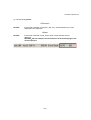
(31) <p.292>, <p.293> Addition of –verbose option to breakpoint command
<Previous>
-
<New>
Input format
breakpoint -information ?-verbose?
Functions
Usage example
(IDCON) 1 % breakpoint -information -verbose
1 Brk00001 enable [S]EX-B [Z]NC [AR]EQ [A]0x10D
40/54
U17839EJ1V0X300.doc
(32) <p.295> Addition of –append option to download command
<Previous>
-
<New>
Added description:
41/54
U17839EJ1V0X300.doc
(33) <p.316> Change in description of the tkcon command
<Previous>
<New>
42/54
U17839EJ1V0X300.doc
(34) <p.320> Change in description of the where command
<Previous>
43/54
U17839EJ1V0X300.doc
<New>
When the message “---Information below might be inaccurate” is displayed, the
subsequent displays may be incorrect.
Example 1
(IDCON) 1 % where
1: test2.c#sub2(int i)#13
2: test.c#num(int i)#71
3: test.c#main()#82
Example 2
(IDCON) 1 % where
1: func2.c# func2()#8
---Information below might be inaccurate.
2: func.c# func(register int_i)#34
3: main.c#main()#77
44/54
U17839EJ1V0X300.doc
(35) Changes in expansion windows
<Previous>
<1><p.326>
Table A-1 List of Expansion Window (Sample)
<2><p.331>
After SymInspect Window
-
<New>
<1><p.326>
Table A-1 List of Expansion Window (Sample)
<2><p.331>
After SymInspect Window
OpenBreak window (addition)
This window is used to set the open break function. [IECUBE]
The open break function is used to set to Hi-Z the timer pins, which control a motor, so
as to stop the motor safely if the motor control signal is not fed back due to CPU
stoppage (break) and the signal may have an adverse effect on the motor.
The device and pins subject to manipulation by the open break function are listed in
the following table. When the open break function is used, the motor stops upon a
break and thus the program cannot be re-executed. In such a case, reset the CPU.
The following shows the operation of the OpenBreak window.
45/54
U17839EJ1V0X300.doc
Figure A-5 OpenBreak Window
•
•
•
When the open break function is set, keep the OpenBreak window open or
minimized. (The setting is cleared when the window is closed.)
The setting made in the OpenBreak window can be saved into the current
project file while the OpenBreak window is open. The setting is restored
together with the settings made in other windows when the project file is
opened next time.
The open break target pins are set to the Hi-Z state by selecting “Category A
(Timer)” in the Peripheral Break area in the Configuration dialog box.
[MINICUBE2]
46/54
U17839EJ1V0X300.doc
(36) <After APPENDIX B EXPANSION WINDOW> Addition of “APPENDIX B CAUTIONS”
<Previous>
-
<New>
APPENDIX B CAUTIONS
This chapter describes general cautions for this product. For details on individual restrictions
or cautions, refer to the Operating Precautions document for each product.
(1) Cautions on switching log-on user of Windows XP
If a log-on user is switched using the Windows XP Switch User function while the ID78K0RQB is starting, the operation of the ID78K0R-QB that was used by the previous user is not
guaranteed. The operation of the ID78K0R-QB used by the new user is also not guaranteed.
(The ID78K0R-QB prohibits duplicated activation on one computer, but duplicated activation
is possible by using the Windows XP Switch User function.)
(2) Cautions related to Windows standby and hibernate modes
If Windows enters standby or hibernate mode while the ID78K0R-QB is starting, the operation
of the ID78K0R-QB is not guaranteed after Windows returns from the mode. In such a case,
restart the emulator and ID78K0R-QB.
(3) Cautions on changing load module file names
If a project file is saved while PM+ and the ID78K0R-QB are active and the load module file
name is changed in PM+, and the debug button of PM+ is clicked while the ID78K0R-QB has
not been started, the load module file of the previous name will be downloaded.
If the debug button of PM+ is clicked while the ID78K0R-QB is already started, the load
module file of the new name will be downloaded.
If the load module file name is changed, the debug button of PM+ must therefore be clicked
while the ID78K0R-QB is already started.
If the ID78K0R-QB is not already started, click the debug button once, start the ID78K0R-QB
and then click the debug button again.
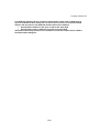
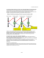
(4) Cautions on Return Out execution for recursive functions
If Return Out is executed during processing of a recursive function (function that calls itself),
the execution cannot return to the desired position. The operation varies as follows according
to how many times the recursive function is called.
Even if the execution fails to return correctly, the subsequent program execution is performed
correctly.
47/54
U17839EJ1V0X300.doc
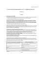
The following shows an operation example.
void func01(char count)
{
count --;
if (count > 0)
{
func01(count); /* 2nd and 3rd call */
}
}
void main(void)
{
func01(3); /* 1st call */
}
In this example, "func01" is the recursive function. The above program flows as follows.
48/54
U17839EJ1V0X300.doc
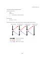
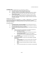
The following explains the Return Out operation in detail.
If Return Out is executed during the first processing of function func01, the execution returns
to the circle-marked position. The ID78K0R-QB sets a breakpoint at this position internally
and executes the program. In this case, the program will stop at the desired position (circlemarked position).
49/54
U17839EJ1V0X300.doc
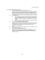
If Return Out is executed during the second and third processing of function func01, as in the
above case, the ID78K0R-QB sets a breakpoint at the desired return position (circle-marked
position).
However, the set breakpoint is also included in the recursive processing, so breaks also occur
at the square-marked positions.
50/54
U17839EJ1V0X300.doc
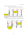
As a result of program execution, a break occurs at the first breakpoint (the rightmost squaremarked position in the above figure), which is not the desired position. This is because the
execution passes through the desired position before reaching the desired position.
Although it is not the desired result, program execution is performed as is coded. Even if the
program is reexecuted from this position, the operation results are normal.
If Return Out is executed after the third func01 processing (the rightmost square-marked
position in the above figure), it is desired to return to the circle-marked position, but a
breakpoint is also set at the square-marked position. This execution breaks at the desired
position, however. This is because the first breakpoint to be reached during recursive
processing is the circle-marked position.
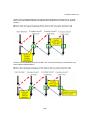
(5) Caution when a function entity is defined in header file
If a function entity is defined in the header file, breakpoint setting, step-wise execution, or
Return Out cannot be performed in the Source window. Moreover, information on this function
is not displayed in the Code Coverage window.
The case where “a function entity is defined in the header file” means that function processing
itself is described in the header file. It does not include the case where only function
declaration, such as prototype declaration and EXTERN declaration, is described in the
header file.
(6) Caution on longjmp function
If Step In or Next Over is performed for the longjmp function, execution processing may not
complete and may wait for a time-out. If Return Out is performed in a function that called the
longjmp function, breaks may not occur.
51/54
U17839EJ1V0X300.doc
(7) Standby mode
The standby mode is released under any of the following conditions.
<1>
The standby mode is entered during step-wise execution.
<2>
Execution is stopped by a forced break in standby mode
<3>
A standby instruction is executed before the execution stops due to a break
after execution or an access break, which takes several extra instructions
until the execution stops.
<4>
A break after execution or an access break is used as an event of a snapshot or event DMM, a standby instruction is executed before the execution
stops due to the break, each processing is complete, and then the execution
is restarted. (IECUBE)
(8) Mirrored non-map area
A mirrored non-map area is not indicated as “??”. If IROM = 64 KB and MAA = 1, for example,
the non-map area starting from address 0x10000 is mirrored. At this time, 0x10000 to
0xF0FFF are indicated as “??” in the Memory window, but values can be read from or written
to 0xF1000 to 0xFFEFF.
(9) External memory
<1>
For external memory, the code coverage cannot be measured and memory
accessing cannot be monitored. (IECUBE)
<2>
When the RAM monitor function is off, data cannot be read from or written to
the external RAM during execution. (IECUBE)
<3>
The following two restrictions apply when a ROM is connected as an external
memory.
(IECUBE)
(a)
If step-wise execution is performed for the following instructions in
instruction mode, an extra instruction is executed.
a.
RETI/RETB instruction
An instruction immediately after returning from the interrupt
servicing will be executed.
b.
Conditional skip instruction (condition is not satisfied)
The instruction next to the conditional skip instruction will be
executed.
(b)
Execution does not stop as is expected if one of the following
operations is performed.
The execution continues, or stops at the next breakpoint. (IECUBE,
MINICUBE2)
a.
Step In in source mode, whose execution stops at a location
in external ROM
b.
Next Over whose execution stops at a location in external
ROM
c.
Return Out whose execution stops at a location in external
ROM
d.
Come Here executed with the cursor placed in external ROM
52/54
U17839EJ1V0X300.doc
(10) Cautions when IECUBE is connected
<1>
Execution operation while external reset signal is input
When the SFR window or the like is displayed and execution or step-wise
execution is performed while an external reset is not masked (the TARGET
RESET check box is not selected in the Configuration dialog box) and an
external reset signal has been input, the program has to wait for a timeout in
communication with the emulator, which drastically degrades the operability.
<2>
Coverage function
(a)
The PC points to the instruction that has not been executed, but for
code coverage measurement, one or two bytes from the top of the
instruction pointed to by the PC are counted by the code coverage
execution. In addition, the address at which a break occurs is also
counted.
(b)
Display of an access being executed does not necessarily change in
the order of access in the Memory window.
<3>
Display of internal ROM area during execution
During execution, data in the internal ROM area before starting execution is
saved temporarily and displayed. The display is therefore not updated until
the execution breaks, even if the data is overwritten by flash selfprogramming or event DMM.
<4>
Events
Up to two extra instructions after a snap-shot event, event DMM, trace event,
or timer event is measured.
<5>
Change of PSW values in DMM dialog box
When changing the PSW values, do not specify a PSW bit (ie, z, rbs1, ac,
rbs0, isp, or cy) in the [Register Name] field in the DMM dialog box. If
attempted, an error message will be output. Be sure to change the PSW
values in 8-bit units.
53/54
U17839EJ1V0X300.doc
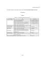
(37) <p.338> Addition of quantitative upper limit list as “B.6. Quantitative Upper Limit List”
<Previous>
-
<New>
54/54