1
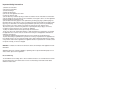
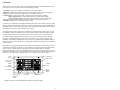
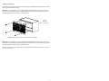
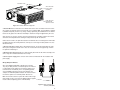
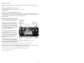
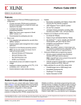
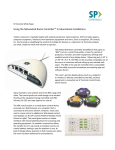
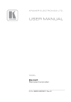
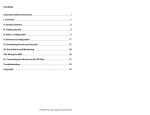
PixiePro Device Control Module
Installation Guide
PX2-MP
Important Safety Instructions
1) Read these instructions.
2) Keep these instructions.
3) Heed all warnings.
4) Follow all instructions.
5) Do not use this apparatus near water.
6) Clean only with dry cloth.
7) Do not block any ventilation openings. Install in accordance with the manufacturer's instructions.
8) Do not install near any heat sources such as radiators, heat registers, stoves, or other apparatus
(including amplifiers) that produce heat.
9) Do not defeat the safety purpose of the polarized or grounding type plug. A polarized plug has
two blades with one wider than the other. A grounding type plug has two blades and a third grounding prong. The wide blade or the third prong is provided for your safety. When the provided plug
does not fit into your outlet, consult an electrician for replacement of the obsolete outlet.
10) Protect the power cord from being walked on or pinched particularly at plugs, convenience
receptacles, and the point where they exit from the apparatus.
11) Only use attachments/accessories specified by the manufacturer.
12) Use only with a cart, stand, tripod, bracket, or table specified by the manufacturer, or sold with
the apparatus. When a cart is used, use caution when moving the cart/apparatus combination to
avoid injury from tip-over.
13) Unplug this apparatus during lightning storms or when unused for long periods of time.
14) Refer all servicing to qualified service personnel. Servicing is required when the apparatus has
been damaged in any way, such as power-supply cord or plug is damaged, liquid has been spilled
or objects have fallen into the apparatus, the apparatus has been exposed to rain or moisture, does
not operate normally, or has been dropped.
WARNING - To Reduce the Risk of Fire Or Electric Shock, Do Not Expose This Apparatus To Rain
Or Moisture.
Apparatus shall not be exposed to dripping or splashing and no objects filled with liquids, such as
vases, shall be placed on the apparatus.
Electrical Warning
The PX2-MP-IR is a low-voltage device. Never install the PixiePro in an electrical back box containing high-voltage wiring. This would cause a serious electrical danger and violate United States
national electrical codes.
i
Contents
Important Safety Instructions ....................................................................
i
I. Overview ...................................................................................................
II. Parts List ..................................................................................................
III. Assembly .................................................................................................
IV. Installation .............................................................................................
V. Wiring .....................................................................................................
VI. Programming ......................................................................................
A. Overview ..............................................................................................
B. Programming Set Up ...........................................................................
C. Simple Programming ..........................................................................
D. Complex Programming .......................................................................
E. Programming the TCM Module ..........................................................
VII. Cloning .................................................................................................
VIII. Configuration ........................................................................................
IX. Operation ...............................................................................................
1
3
4
5
7
9
9
9
10
11
15
17
19
26
Technical Specifications ............................................................................ 27
Warranty ...................................................................................................... 27
FCC Compliance ........................................................................................ 27
PX2-MP-IR User’s Manual (Version C) 30MAY2006
I. Overview
Welcome to the user’s manual for your new PixiePro Modular Panel™! This manual documents all
of the steps necessary to get the PixiePro up and running, including:
-
Assembly of the PixiePro, including customization of the button modules
Mounting, including tabletop-mounting and wall-mounting (both flush- and surface-mounting)
Wiring the PixiePro to one infrared (IR) emitter, or to multiple IR emitters
Programming the codes from IR remote control devices into the PixiePro, including:
- Simple Programming: a single IR code learned by a single PixiePro button
- Complex Programming: a series of IR codes learned by a single PixiePro button
- Cloning or copying all of the settings and learned codes from one PixiePro to another
- Configuring settings on the PixiePro to optimize control
The PixiePro is a stand-alone IR-learning audiovisual control device. One PixiePro may learn codes
from the remote controls of many devices, or of just one. IR output may be wired to multiple devices
using additional IR emitters (ordered separately - SP Controls part no. PXE-EMIT). For instructions
about wiring the PixiePro, go to the Wiring section on page 7.
An example of an AV system that can be controlled by the PixiePro might consist of some or all of
the following elements (each with their own infrared remote control): projector, DVD player, laptop
computer, VCR, document camera, cable television receiver, electric screen, and other devices.
The PixiePro ships in a plastic surface mount box. It may be removed from the plastic box and
mounted into a standard four-gang metal switch or junction box, or four-gang mud ring for wall
installation. If used with a metal back box, be sure to use the included screws and plastic washers.
For instructions on mounting the PixiePro, including wall- and tabletop-mounting, see the Installation
section on page 5.
Each button may be programmed with up to 16 codes from any number of remote controls, up to a
maximum of 768 codes for the PixiePro. A single button on the PixiePro may be programmed with
just one code (see Simple Programming on page 10) or with multiple codes (see Complex
Programming on page 11). The codes programmed to a single button may be grouped in any combination of round robin or macro. Delay lengths between codes in a macro can be varied to optimize
performance. For instructions on learning codes, see the Programming section on page 9.
Power
Buttons
Menu/Security
Button Module
Security and
Timer Activity
Display
VCR/DVD
Control
Volume
Control/Display
Device
Up/Down
Buttons
Aux Up/Down
Ambient Light
Adjustment
Sensor
Aux Buttons
Source Buttons
Figure 1: PixiePro with all standard button modules inserted (as it ships)
1
The flexible interface may be customized to your requirements. Most buttons may be replaced by
blank button modules if unneeded. PixiePro can control almost any IR-controllable device. The
PixiePro may be field-programmed in minutes using IR-learning technology. Configuration and programming may be quickly and easily copied to multiple units with CAT5 cable, or using wireless
cloning technology. For instructions on assembling PixiePro button modules, see the Assembly section on page 4.
Unneeded
buttons may be
replaced with
blank plastic.
Two aux buttons with two blanks
Figure 2: PixiePro with blank button modules inserted in some areas
PixiePro has configurable features including automatic brightness adjustment, security code lockout,
automatic inactivity shutdown timer, multiple-device transport control, and many others that will be
described later in this manual. The default configuration settings on the PixiePro will be suitable for
the majority of users. If you want to learn about the configuration options, or change any of those,
go to the Configuration section on page 19.
For multi-room installations, in which each room has an identical projector, learned codes and configuration settings can easily be copied or “cloned” from one PixiePro to another. This can be done
either wirelessly or through CAT5 cable. For instructions on copying settings and codes from one
PixiePro to another, see the Cloning section on page 17.
2
II. Parts List
Note: Keep all button inserts and included materials, even if some modules are not currently
used. They may be required in the future for changing the PixiePro configuration settings, reprogramming the PixiePro, or changing equipment in the room.
The PixiePro ships with:
PixiePro main board
1 four-gang plastic surface mount box
1 custom plastic wall plate
Rubberized button modules:
- 1 toggling power module
- 1 discrete power on/off module
- 1 status LED module - projector icon
- 1 status LED module - monitor icon
- 1 volume control/display button module
- 8 source selection button modules
- 4 aux control button modules
- 1 ambient light sensor dome
- 1 menu/security button module
- 1 transport control/menu button module
- 1 device up/down button module
Plastic blank button replacement inserts:
- 1 volume module blank
- 1 aux up/down blank
- 3 two-button source selection blanks
- 1 one-button source selection blank
- 4 aux button plastic negatives
- 1 menu control module blank
- 1 transport control/menu module blank
- 1 device up/down button module blank
Plastic button overlay anchors for all button module types
1 plastic bezel
1 IR emitter with fiber optic output assembly
Velcro™ tape
1 regulated power supply
1 sheet of non-adhesive, transparent button legends
4 screws/washers (for back box mounting)
2 wall anchors/screws
Optional Accessories and Parts:
PXE-EMIT - additional IR emitter with fiber optic output assembly (required for control of multiple
devices - one per device)
PXE-DCM-PS (additional power supplies required for installations with more than six IR emitters)
3
III. Assembly
Plastic
Overlay
Circuit
Board
Bezel
Rubberized
Button Pads
Figure 3: The four basic components of the PixiePro
1. Preparation
Note: When assembling the PixiePro, you will be working with a number of small parts. Be sure that
you assemble the PixiePro in a clean, well-lighted work area.
Disassemble the PixiePro (see Figure 3 for an example of a disassembled unit) and select desired
button insert modules. Most button modules may be replaced with blanks if desired. You must use
the Status LED module, at least one source selection module, and at least one power module.
Most button modules are optional and may be replaced with blanks. For example, if you do not wish
to include control of a DVD player or VCR in your installation, you may replace the VCR/DVD control module with blank inserts. You may likewise assemble the PixiePro with anywhere from 0-4 aux
control buttons and 1-8 source selection buttons.
Note: Programming and configuring the PixiePro requires use of the volume control/display module,
all four aux button modules, and at least the first seven source buttons. Be sure to include these
modules until the unit has been configured. They may then be replaced with blanks. You may clone
configuration from another unit without including these modules.
The PixiePro security feature requires use of the menu button module for entering security codes.
Several configuration settings require use of the discrete on/off power button module. See the
Configuration section on page 19 for more information.
2. Assembly
a. Select the appropriate button modules. Button modules are connected in sets, but may be easily
separated for customized configuration. To separate modules, fold the buttons away from each other
to expose the thin connecting rubber and cut with a razor knife.
b. Place the desired button modules and blanks against the circuit board.
c. Label the selected buttons. Remove the non-adhesive transparent labels from the included legend sheet and inserting them in the plastic overlay legend receptacles. Be sure to verify the correct
orientation.
d. Fit the plastic overlays over the rubberized button pads and/or blanks. Secure the overlays in
place by fitting the plastic bezel over all modules. Be sure the bezel is right side up.
4
IV. Installation
PixiePro may be mounted using the plastic surface-mounting box (included), or using a standard
four-gang wall box (must be purchased separately).
Warning: The PX2-MP-IR is a low-voltage device. Never install the PixiePro in an electrical back
box containing high-voltage wiring. This would cause a serious electrical danger and violate United
States’ electrical codes.
Wall Anchors
(included)
Release clasps to remove
PixiePro from surface box
Wall Anchors
PixiePro Circuit
Board
Plastic Surface
Mount Box
(included)
Figure 4: Assembling the PixiePro for surface mounting (surface-mount box included)
1. Wall Surface Mounting
The PixiePro may be surface mounted to masonry or drywall with the included plastic surface mount
box and anchors.
Secure the surface mount box to the wall. Bring the three-conductor cable from the cable assembly
to the back box and feed it through one of the cable channels, located at the top and bottom of the
box. Wire mold may be used to guide wiring along the wall.
To secure the PixiePro into the plastic mounting box, line the circuit board up with the box posts and
insert securely into the plastic clasps.
Cover the PixiePro face with the included faceplate and secure with the included screws.
2. Tabletop Surface Mounting
Secure the PixiePro plastic surface mount box to the table. Thread the three-conductor cable from
the cable assembly to the back box and feed it through the wiring cutout. Wire mold may be used to
guide wiring along the table. Alternately, you may cut an access hole through the table and run
wiring along the underside of the table.
To secure the PixiePro into the surface mount box, line the circuit board up with the box posts and
insert securely into the plastic clasps.
Cover the PixiePro face with the included faceplate and secure with the included screws.
5
3. Wall Flush Mounting
The PixiePro may be flush mounted into a wall using either a standard four-gang back box and conduit, or using a four-gang mud ring.
Back Box: Cut a four-gang hole in the wall and install a standard four-gang wall box. Secure the
PixiePro into the wall box using the included mounting screws. Cover the PixiePro face with the
included faceplate and secure with the included screws.
4-Gang
Back Box
(not included)
Figure 5: Mounting the PixiePro in a back box (not included)
Mud Ring: Cut a four-gang hole in the wall and install a standard four-gang mud ring. Secure the
PixiePro into the mud ring (not included) using the included screws. Cover the PixiePro face with the
included faceplate and secure with the included screws.
Note: SP Controls strongly recommends use of a mud ring for mounting the PixiePro in sheet rock
to ensure a secure fit.
6
V. Wiring
A. Wiring Controller
Wiring PixiePro to Control a Single Device
Attention! Remove power from the IR emitter
before wiring to PixiePro. Do NOT attempt to
connect the wires to the PixiePro while it is powered. Doing so may damage the unit.
+6
GND
IR
RS232 TX
Connect the three-conductor cable to the captivescrew connector on the back of the PixiePro. Be
sure that the wires agree with the connections on
the cable assembly block end (diagram below).
Note: The output position labeled RS232TX and
the female RJ45 port on the PixiePro are for
future use with other SP Controls hardware.
+6
GND
IR
RS232 TX
Wiring PixiePro to Control Multiple Devices
The PixiePro ships with just one IR emitter; each
additional device that the PixiePro controls will
require an additional IR emitter (not included, part
no. PXE-EMIT).
Figure 6: Wiring the controller
Note: The PixiePro may be used to drive a maximum of six IR emitters with a single power supply.
To drive more than six, additional power supplies must be ordered (part no. PXE-DCM-PS).
All three wires of the PixiePro output must be wired in parallel to each emitter that will control a
device. The cable assembly blocks may be wired in a star pattern out from the back of the PixiePro,
or daisy-chained from one assembly block to the next, use whichever method requires the least total
line length.
For a diagram of daisy-chained wiring between two IR emitters, see Figure 9 on page 8.
B. Wiring IR Emitter
3-conductor
to PixiePro
Wiring IR Emitter to Control a Single Device
Attention: The optical fiber that extends from the PixiePro terminal
block cannot be extended. DO NOT CUT it without proper fiber optic
cutting tools.
Wire the cable assembly to the PixiePro using a three-conductor
cable (not included). SP Controls recommends using 18- or 20gauge cable. Standard audio cable will work (e.g., Belden™ 8451
or 9451).
1. Wire Cable Assembly. Connect the three-conductor cable to the
screw down posts in the cable assembly block. The three positions
on the cable assembly block are labeled +6V, GND, and IR. Match
the conductors to the corresponding positions on the captive screw
connector on the back of the PixiePro.
Fiber Optic
Cable to IR
Receiver
Window
Connect
6 VDC
Figure 7: IR emitter
7
3-conductor cable
Affix emitter with
Velcro™ Tape
(included)
Guide fiber optic
light pipe with
adhesive anchors
Figure 8: IR emitter affixed to a projector
2. Position IR bud over infrared-receiver window of the device to be controlled. Remove the backing to expose the adhesive and secure bud to IR receiver window. Note: The bud adhesive gradually solidifies and quickly becomes very strong, making repositioning the bud difficult. Be sure that the
bud is correctly placed. The adhesive will solidify to maximum strength in approximately 24 hours.
Some devices are extremely sensitive to precise bud placement. If possible, program the PixiePro
and test the IR bud position before affixing the bud permanently with the adhesive.
Unlike some IR emitters, the optic fiber bud does not illuminate when it sends signal. An LED inside
the plastic assembly does visibly illuminate, and may be seen through the black plastic in the area
labeled IR Activity.
3. Anchor optic fiber to display device with included anchors. The anchors will position the optic
fiber in place and guide it around corners. Use care not to bend it at a sharp right angle. A kink in
the optic fiber will damage it.
4. Draw the optic fiber taut to place the cable assembly block. Affix the IR emitter assembly to the
device using the included double-sided Velcro™ tape.
5. Connect power supply barrel connector to IR emitter terminal block with the included 6-VDC
power supply.
Wiring Multiple IR Emitters
Wire each additional PXE-EMIT in parallel to the PixiePro.
They may be daisy-chained, or wired directly from the PixiePro
in a star pattern. Each position on the PixiePro captive screw
terminal must be wired directly to the corresponding position
on the PXE-EMIT assembly as shown in the diagram. For
example, the PXE-EMIT position labeled +6V must be wired to
the PixiePro captive screw terminal position labeled +6V.
Note: The PixiePro can drive up to six IR emitters with a single
power supply. To drive more than six, additional power supplies
To PixiePro
must be ordered separately (part no. PXE-DCM-PS).
Figure 9: Daisy-chained IR
emitters (PXE-EMIT)
8
VI. Programming
A. Overview
The PixiePro controls devices by learning and duplicating the IR codes of their remote controls.
Each button may programmed with either a single code (see Simple Programming on page 10) or
as many as 16 codes with a configurable delay between each (see Complex Programming on page
11).
Each button may be configured to send:
- one single code
- multiple codes in “round robin” (alternating codes sent on subsequent button presses)
- multiple codes sent with a single button press (macros)
- multiple groups of codes sent round robin (“round robin” macros)
B. Programming Setup
Insert paperclip to enter
learning mode
1. Power the PixiePro: While powered, the LED
backlights will illuminate.
2. Enter Learning Mode: To set the PixiePro to
learning mode, gently insert a paper clip into the
small hole labeled insert paper clip to learn.
The Learning Mode indicator LED will blink red
while the PixiePro is in learning mode.
Caution: Be gentle with the paper clip to ensure
that you do not damage the switch mechanism.
Some lighting, especially fluorescent light and
sunlight, can interfere with the ability of the
PixiePro to learn. If the room is too bright for programming, the Learning Mode Indicator will illuminate solid red, the buttons will beep as soon as
they are pressed, and they will not arm for learning. Should this occur, shield the PixiePro from
the ambient light while learning.
Status LED
Learning Mode
Aperture
Figure 10: Entering learning mode
Note: Be sure not to depress any buttons while inserting the paperclip or the PixiePro will enter
Configuration Mode. You will know it is in Configuration Mode if it begins clicking.
3. Test Remote and Identify Sweet Spot: Before trying to learn any buttons, position your remote
control a few inches from the IR learning eye. When you press a button on the remote, you should
see the PixiePro Learning Mode Indicator LED flicker. Notice that as you move the remote closer
and farther away from the receiver window, or as you move "off axis" (away from perpendicular to
the receiver window) the brightness of the red flashes will fall off and become intermittent. Identify a
position that seems to consistently yield clear, regular blinking of the red Learning Mode Indicator
LED. This is the "sweet spot" most likely to provide the clean signal that the PixiePro needs to learn.
If you do NOT see the Learning Mode Indicator LED flicker rapidly, your remote may need new batteries, or may be beaming something besides IR.
4. Learn IR Codes: To program a button with a single IR code, see Simple Programming on page
10. To program a button with multiple codes, see Complex Programming on page 11.
9
C. Simple Programming
Simple programming assigns a single code to a button.
1. Press a Button on the PixiePro: Press the button you want to program a single time to arm it
for Simple Learning. It should beep once, and the button will slowly blink to indicate that it is ready.
Note: If the button beeps twice, you have accidentally armed the button for Complex Learning.
Press any other button to bring the button out of Complex Learning, and then rearm the button for
Simple Learning.
2. Aim the Remote Control at the IR Window: Position the remote control in the sweet spot you
previously identified.
3. Zap the PixiePro: Press and hold
the remote control button for approximately one second. You should see
the Learning Mode Indicator LED flicker,
indicating that the code is being
received. The PixiePro will beep three
times quickly to indicate successful
learning.
Arming will time out in approximately 30
seconds if no IR code is received.
You may select a different button for
learning at any time, including buttons
that have already been learned. If you
re-press a button that has been armed
for learning, it will be disarmed.
Figure 11: Arm button for learning
If the PixiePro believes it successfully learned the code, the button will begin flashing quickly to indicate it is in Verification Mode.
4. Verify the IR Code was Learned Correctly: Immediately after learning, each button will blink
rapidly to indicate that it is ready for verification. Pressing that button will transmit the code as it was
learned. If the IR emitter has been properly placed on the device, you may test that the learned
code will correctly control that device.
Note: The optic fiber bud will not illuminate while sending codes, but an LED on the plastic assembly labeled IR Activity will glow visibly upon close inspection.
To re-learn a button that did not seem to learn correctly, simply press any other button on the button
pad, then press the target again to re-arm it.
Figure 12: Close-up view of IR emitter
IR Activity LED
10
D. Complex Programming
Complex programming assigns multiple codes to a single button, and defines how those codes will
be sent out. Each button may be programmed with up to 16 codes, which can be sent inside macros
(multiple commands grouped to play back sequentially upon a single button press), in “round robin”
fashion (different individual codes sent on alternating button presses), or in a combination of the two
(macros sent in an alternating fashion).
To program multiple codes to a single button, each code must have either a delay or a round robin
stop separating it from other codes.
Complex Programming: Step-by-Step Instructions
1. Arm the Button for Learning. While the PixiePro is in Learning Mode, press the target button
twice quickly to arm it for complex programming. It should beep twice and slowly blink to indicate
that it is armed for learning. Hold the remote control in the sweet spot you previously identified.
Note: If the button beeps only once, you have accidentally armed it for Simple Learning. Press any
other button to exit Simple Learning mode. Now rearm the button for Complex Learning.
2. Learn the First Code. Position the remote control in the sweet spot and beam the first code to
be learned. The PixiePro should beep three times to indicate success.
3. Specify a Stop or Delay. Use the Volume Up button to scroll through the stop and delay choices (see Stop and Delay Values chart on page 12). Once you reach the stop or delay you wish to
use, press a Power button to confirm that selection. If you are using the Power button module with
both On and Off power buttons, either can be used to confirm your selection. Note: By default, a
macro will continue sending until it is complete, and will not allow any other command from the
PixiePro. The hourglass LED will remain illuminated for as long as the sequence is sending. Keep
this in mind before configuring long delays between codes.
Final Stop indicates this button is done with learning and you will program no more
codes. Final Stop is the first stop you will see after beaming a code while in Complex
Learning Mode. Press a Power button to select. The PixiePro will beep four times rapidly
to indicate Final Stop has been accepted, and will then beep three times more slowly to
indicate that the button is completely programmed and has entered Verification Mode.
Note: If a button is disarmed at any point during programming prior to programming a
Final Stop, all learned codes will be lost.
Round Robin Stop specifies that the current button press is complete, and you are ready
to enter the first code for the next button press (i.e. the next round robin code). Hit the
Volume Up button a single time to reach Round Robin Stop, then press a Power button
to select. The PixiePro will beep four times rapidly to indicate that the Stop has been
accepted, and will then beep twice more slowly to prompt you to learn the next code.
Delays 0-0 through 3-7 specify different delay times between codes (see Stop and Delay
Values table on page 12). These delays can be as short as 100 milliseconds (Delay 0-0)
or as large as 10 minutes (Delay 3-7). After each delay has been entered, the PixiePro
will beep four times rapidly to indicate that the delay has been accepted.
4. Finish Programming. Repeat steps 2 and 3 above for the next codes in the sequence. Note: to
finish programming a button, the last choice must be Final Stop. This indicates that you are all done
learning codes for this button.
5. Verification Mode: Immediately after finishing learning all codes, the button will blink rapidly to
indicate that it is ready for verification. Press it to verify that the codes were learned correctly. The
PixiePro will emit the codes as they were learned. Because the PixiePro will emit the codes during
this step, you may test that the learned codes will correctly control the device or devices.
11
Stop and Delay Values
Display Examples
Stops
Final Stop
Finished learning, no more
codes
Round Robin Stop Finished learning this button
press, ready to enter first code
for next button press
Delay
Length
Delay
Delay
Delay
Delay
Delay
Delay
Delay
Delay
0-0
0-1
0-2
0-3
0-4
0-5
0-6
0-7
100
200
300
400
500
650
750
850
Delay
Delay
Delay
Delay
Delay
Delay
Delay
Delay
1-0
1-1
1-2
1-3
1-4
1-5
1-6
1-7
1s
1.5
2s
2.5
3s
3.5
4s
4.5
Delay
Delay
Delay
Delay
Delay
Delay
Delay
Delay
2-0
2-1
2-2
2-3
2-4
2-5
2-6
2-7
5s
7.5 s
10 s
12.5 s
15 s
20 s
30 s
45 s
Delay
Delay
Delay
Delay
Delay
Delay
Delay
Delay
3-0
3-1
3-2
3-3
3-4
3-5
3-6
3-7
1 minute
1 m 30 s
2m
2 m 30 s
3m
5m
7.5 m
10 m
ms
ms
ms
ms
ms
ms
ms
ms
Final Stop
Round Robin
Stop
Delay 0-1
s
s
Delay 0-7
s
s
Delay 1-1
Delay 2-7
Delay 3-7
Delays: Select Delay 0-0 through 3-7 to specify a delay between codes that are to be sent as a
macro. After each delay has been entered (pressing a Power button confirms the selection), the
PixiePro will beep four times rapidly to indicate that the delay has been accepted.
12
Complex Programming: Examples
Example 1: Program three individual codes to be sent in a round robin fashion (alternating codes on
subsequent button presses).
Example 1:
Round Robin
1st Button
Press
2nd Button
Press
3rd Button
Press
4th Button
Press
5th Button
Press
Code A
Code B
Code C
Code A
Code B
1. Arm button for complex learning
2. Learn code A
3. Select Round Robin Stop - done learning codes for first button press
4. Learn code B
5. Select Round Robin Stop - done learning codes for second button press
6. Learn code C
7. Select Final Stop - done learning all codes
Example 2: Program one macro, consisting of three codes to be sent sequentially
ton press, with a 300 millisecond delay between each code.
1st Button
2nd Button
3rd Button
4th Button
Press
Press
Press
Press
Example 2:
3-Code Macro
Code A
Code A
Code A
Code A
Delay
Code B
Delay
Code C
Delay
Code B
Delay
Code C
Delay
Code B
Delay
Code C
Delay
Code B
Delay
Code C
with a single but5th Button
Press
Code A
Delay
Code B
Delay
Code C
1. Arm button for complex learning
2. Learn code A
3. Select Delay 0-2 - 300 ms
4. Learn code B
5. Select Delay 0-2 - 300 ms
6. Learn code C
7. Select Final Stop - done learning all codes
Example 3 - Program two macros of three codes each, with a 500 millisecond delay after each
code within the macros. The two macros are to be sent in a round robin fashion.
1st Button
2nd Button
3rd Button
4th Button
5th Button
Press
Press
Press
Press
Press
Example 3:
Code A
Code D
Code A
Code D
Code A
Two 3-Code
Delay
Delay
Delay
Delay
Delay
Macros in Round
Code B
Code E
Code B
Code E
Code B
Robin
Delay
Code C
Delay
Code F
Delay
Code C
Delay
Code F
Delay
Code C
1. Arm button for complex learning
2. Learn code A
3. Select Delay 0-4 - 500 ms
4. Learn code B
5. Select Delay 0-4 - 500 ms
6. Learn code C
7. Select Delay 0-4 - 500 ms
8. Select Round Robin Stop - done learning codes for first button press
9. Learn code D
10. Select Delay 0-4 - 500 ms
11. Learn code E
12. Select Delay 0-4 - 500 ms
13. Learn code F
14. Select Final Stop - done learning all codes
13
To Erase a Single Button
While in Learning Mode, press and hold a button that has been programmed to erase it. The button
will begin blinking slowly to indicate that it is going to be erased. Blinking will gradually quicken and,
after several seconds, the button will go dark and beep four times to indicate that erasure is complete.
To Erase All Buttons on the TCM only
Press and hold any two buttons on the PixiePro TCM while the PixiePro is in Learning Mode to
erase the TCM section. The TCM buttons will begin blinking slowly to indicate that it is going to be
erased. Blinking will gradually quicken to confirm TCM erase. After a few seconds, all buttons on the
TCM will go dark and the PixiePro will beep four times, indicating that the TCM has been erased.
Once a device or button has been erased there is no way to un-erase it.
If the PixiePro is configured to use Multiple-Device mode for the TCM, this will erase the last-selected device only. Any other code sets programmed to the TCM, and codes programmed to the
PixiePro, will not be erased.
To Erase All Buttons on PixiePro, including all TCM codes
While in Learning Mode, press and hold any two buttons to erase the entire device. If the PixiePro is
configured to use Multiple-Device mode for the TCM, at least one of the buttons must be outside of
that module to erase the entire device (e.g., one of the source buttons or power buttons).
The whole button pad will begin blinking slowly to indicate that it is going to be erased. Blinking will
gradually quicken to confirm device erase. After a few seconds, all buttons will go dark and the
PixiePro will beep four times indicating that it has been erased. All code sets programmed to the
TCM will be erased along with the other buttons. Once the PixiePro has been erased there is no
way to un-erase it.
Configuration settings will not be changed by device erase.
14
E. Programming the Transport Control/Menu Module (TCM)
The Transport Control/Menu Module (TCM) may be configured for SingleDevice or Multiple-Device mode (to enable Single-Device mode, see the
Configuration section on page 19).
In Multiple-Device Mode, the TCM may be programmed with as many as
nine different code sets for devices you wish to control (e.g. VCR, DVD
player, CD player, document camera, etc.). The TCM will control the device
that corresponds to the currently selected input source.
Example: The TCM may be programmed with codes for a VCR and a
DVD player. When the VCR source is selected on the PixiePro, the TCM
will switch to the VCR codes. When the DVD source is selected, the TCM
will switch to the DVD code set. The buttons you have programmed for
each device will illuminate only when their associated Source button is
selected.
Both or either modules may be configured with keypads; either will function
Figure 13: Transport
independently in Single Device mode or Multiple-Device mode.
Control/Menu Module
Single-Device TCM Programming: Program the TCM buttons normally
(see Simple Programming and Complex Programming sections) to control
just one device.
Multiple-Device TCM Programming: To arm the TCM to learn a code set associated with a specific device (e.g., a DVD player), press the associated Source button while in Learning Mode. Any
button programmed on the TCM will be associated with the last-selected Source button. You may
completely program the TCM with a separate code set associated with each of the eight Source
buttons.
Example:
1. Configure the PixiePro to Multiple-Device mode (see Configuration below).
2. Set the PixiePro to Learning Mode.
3. Press the Source 1 button to activate the Source 1 Code Set Profile on the TCM. Note that this
will arm Source 1 for learning. It is not necessary to program the Source button at this time.
4. After pressing the Source 1 button, press a button on the TCM that you wish to learn a code for.
5. Learn the desired codes on the TCM to be associated with Source 1 by repeating step 4.
6. Press the Source 2 button to activate the Source 2 Code Set Profile on the TCM.
7. Learn the desired codes on the TCM to be associated with Source 2.
8. Continue for any Source Buttons you would like to associate commands with.
You may leave as many Source profiles unprogrammed as you wish.
Device 0
In addition to the eight Source buttons, the TCM may also be programmed with another device,
referred to as device 0. During operation, device 0 becomes selected whenever the currently
selected Source button is pressed a second time. This may be useful for accessing projector
menus when any source is active.
To program the TCM device 0 profile, press the currently selected Source button a second time
while in Learning Mode.
To Exit Learning Mode
Gently remove the paper clip from the Learning Mode aperture to exit Learning Mode.
15
Final Test of Learned Codes
Verify that the IR bud has been placed directly over the IR detector on the device the PixiePro controls. Press the PixiePro button that you wish to test. A red LED (labeled “IR Activity” inside the plastic assembly will blink when the code is being sent, but the IR bud will not illuminate.
Programming Philips, Magnavox, and Koss Devices
Philips and their OEM partners Magnavox and Koss use a unique IR protocol that requires special
handling during programming.
Most IR remotes send the same code each time a button is pressed. Philips remote controls alternate codes, sending code A the first time the button is pressed, code B the next time the button is
pressed, code A the third time, etc. Philips devices only respond to alternating codes.
For example, if you press the VOLUME UP button on a Philips remote, the remote will send code A
and the device will respond. If you then cover the remote and press VOLUME UP again, the remote
will send code B, but the device will not receive it. If you then press VOLUME UP again, pointed
toward the device, the device will not respond. It will only accept code B at this point.
Because the Philips remote control sends alternating commands, round robin codes must be used
to program single keys with multiple codes. To program round robin codes, see Complex
Programming on page 11.
Troubleshooting
If the cable assembly LED blinks and you cannot control the device, BE ABSOLUTELY SURE that
the IR bud is located in the right place. If it still does not work, test other programmed buttons. If
some work but others do not, try re-programming the buttons that do not work.
Be sure to press the button on the remote for at least one second while learning.
If you have gone through all of these steps and still cannot control the device, it may have an IR format that cannot be learned. Note that this is extremely rare and it is much more like that the IR is
miswired, the bud is improperly placed, etc.
If you are unable to control a device, verify that the configuration option High Frequency Carrier
Default is enabled. and try again.
Note: A small number of remote controls use RF instead of IR. The PixiePro cannot learn or replicate RF codes.
Please contact SP Controls if you believe you have a device that cannot be controlled.
16
VII. Cloning
Cloning Overview
Any PixiePro may quickly copy all the programmed codes and configuration settings from any other
PixiePro wirelessly, or using a standard CAT5 cable. For multiple-room installations, this will greatly
speed up the process.
When cloning the PixiePro, there is a Donor Unit and a Clone Unit. The Donor Unit must be programmed with the appropriate codes normally prior to cloning. The Clone Unit will receive the Donor
Unit's codes and configuration settings.
Both PixiePros must be assembled with the same button inserts. For example, if the donor PixiePro
has a toggling power button insert, the clone PixiePro must also have a toggling power button insert.
In order to clone one PixiePro to another, both units must be powered.
Wireless Cloning Procedure
1. Set the Clone Unit to cloning mode. To do that, gently insert a paper clip into the IR Learning
aperture. Press and hold any button on the Clone Unit and, while holding the button, remove the
paper clip.The PixiePro will rapidly chirp for as long as it remains in cloning mode. The PixiePro will
time out of cloning mode in about 15 seconds, so have both devices on hand. If the PixiePro times
out of cloning mode, simply repeat this procedure to return it to cloning mode.
2. Position the two units face-to-face, with both units held upright, approximately one inch apart. The
two units should be directly across from each other with the bezels lined up. This will position the IR
receiver window of the cloning PixiePro directly across from the IR transmitter in the donor PixiePro.
Note: Be sure not to cover or obstruct the IR receiver window or transmitter with your hands.
Once the units are correctly lined up, the donor PixiePro will automatically enter cloning mode.
When the clone PixiePro makes contact with the donor, its LED
will also turn solid red.
3. Hold the Clone Unit steadily in front of the donor for approximately 80 to 90 seconds. Both units will chirp rapidly to indicate
their progress. If the connection is broken (the Clone Unit ceases
to chirp), reposition the Clone Unit and the PixiePros will pick up
where they left off. If communication is broken for a significant
period of time (about 15 seconds), the Clone Unit will time out
and you will need to begin cloning again.
4. When the Clone Unit has completed copying codes from the
donor, it will beep loudly 3 times and reset. You will see all of the
button LEDs flicker in quick succession. After the PixiePro has
reset it will be fully operational, and it will have learned all of the
codes programmed into the Donor Unit.
The Donor Unit will remain in cloning mode for approximately 15
seconds until it times out. It will then return to normal operation.
Position Clone Units
approximately 1”-2” apart
Figure 14: Positioning PixiePros
during wireless
cloning procedure
17
Cloning Procedure Using CAT5
PixiePro units may be cloned using CAT5, CAT5e, or CAT6 cable, eliminating the need to hold the
units upright for the duration of cloning. Cloning over CAT5 takes approximately two minutes.
1. Connect the two units with a straight CAT5, CAT5E, or CAT6 cable. Plug the cable into the female
RJ45 receptacles on both units to make connection. Cloning will not work with a null modem cable.
2. Set the donor PixiePro to Configuration Mode. Press and hold any button while gently inserting a
paper clip into the small hole labeled "insert paper clip to enter Learning Mode". The PixiePro will
enter Configuration Mode, indicated by a blinking red Learning Mode Indicator LED on the front of
the PixiePro and a continuous clicking sound. The PixiePro will remain in Configuration Mode while
the paper clip remains in the Learning Mode aperture.
3. Set the Clone Unit to cloning mode. Gently insert a paper clip into the IR Learning aperture.
Press and hold any button on the Clone Unit and, while holding the button, remove the paper clip.
Caution: Be gentle with the paper clip to ensure that you do not damage switch mechanism.
The PixiePro will rapidly chirp for as long as it remains in cloning mode.
4. The Clone Unit will wait for a wireless cloning signal for about 10 seconds. During this time the
Donor Unit will remain inactive. After 10 seconds, the Clone Unit will begin wired cloning, and both
units will begin clicking for about 2 minutes.
5. When the Clone Unit has completed copying codes from the donor, it will beep loudly 3 times and
reset. You will see all of the button LEDs flicker in quick succession. After the PixiePro has reset it
will be fully operational, and it will have learned all of the codes programmed into the Donor Unit.
18
VIII. Configuration
Power buttons are
used as an Enter key
in configuration mode
Use Source 1-8
to select Setting
Volume Control and
Display used to set
Levels
Aux Buttons 1-4
select Configuration
Group
Figure 15: Configuring the PixiePro
Overview
Configuration Mode is used to change the various settings on the PixiePro that control its behavior.
By default, the settings on the PixiePro will be
To put the PixiePro into Configuration Mode, press and hold any button while inserting the paperclip
into the programming aperture. The PixiePro Learning Mode Indicator LED will flash and the unit will
emit a regular clicking sound to indicate it has entered Configuration Mode.
Once in Configuration Mode, use the PixiePro interface to navigate through the configuration settings. The Aux buttons are used to set the configuration group. Source buttons 1-8 are used to
select the setting you wish to adjust within the current group. Volume buttons are used to select the
desired value for a given setting, with the volume display providing feedback. Power buttons are
used to confirm selections.
The Volume Control/Display module, all four Aux button modules, and at least seven Source buttons
are required to fully configure the PixiePro. Be sure to include these modules until the unit is configured. After configuration, they may be replaced with blanks. You may clone settings from an
already-configured unit without including these modules.
In an emergency where the button modules are unavailable, you may simulate button presses by
removing the blanks and carefully probing the button key with screwdriver or thin metal object.
If the button modules are unavailable, gently touch these contact
points with a fine metal implement
to simulate a button press.
Figure 16: Simulating a button press when button module is unavailable
19
Configuration Settings
Group 1 - Core Functions
- Setting 1 - Multiple-Device TCM Mode
- Setting 2 - “Device 0” on TCM in Multiple-Device Mode
- Setting 3 - Input Selection Lights on TCM Persist in Single-Device Mode
- Setting 4 - Defeat In-Progress Macro on Button Press
- Setting 5 - Fixed-Length Code Learning
- Setting 6 - Fixed-Length Code Learning Applies to Single-Code Learning
- Setting 7 - High-Frequency Carrier Default
Group 2 - Timers
- Setting 1 - Automatic Shutdown Timer
- Setting 2 - Warm Up Display Timer
- Setting 3 - Cool Down Display Timer
- Setting 4 - Security Retry Lockout Timer
Group 3 - Security
- Setting 1 - Enable/Disable Security Lock
- Setting 2 - Lock on Inactivity Shutdown
- Setting 3 - Enter or Retrieve Security Code
Group 4 - Interface Settings
- Setting 1 - Button Click On/Off
- Setting 2 - Click on Every Macro Send
- Setting 3 - LED Brightness Level
- Setting 4 - Enable Ambient Light Adjust
- Setting 5 - Volume Animation On/Off
- Setting 6 - Press-and-hold Off
Setting Configuration Values
Settings are of two types: toggling and scalar. Toggling settings are either on or off. Scalar settings
have values within a range, the lowest setting being 0-0, the highest being 3-7.
Use the Volume Up and Volume Down buttons and display to adjust each setting. Toggling settings
toggle between on (indicated by “splayed” or alternating Volume Display lights illuminated) and off
(indicated by one LED in the center of the Volume Display illuminated). Scalar settings may be set
to 32 different values, ranging from 0-0 through 3-7. See the figure below for examples.
Toggle - Off
Toggle - On
1-7
0-1
0-0
2-7
3-1
0-7
3-7
Figure 17: Volume Display setting examples for toggling
and scalar values
20
Configuration Setting Descriptions
Group 1 - Core Functions
Core function settings determine behavior of PixiePro.
Setting 1 - Multiple-Device TCM Mode (toggle)
Enable this setting to allow the TCM to control multiple devices. Disable to always control a single
device with the TCM module. See Section IX Operation for more information.
Default: Enabled (Multiple-Device Mode)
Setting 2 - “Device 0” on TCM in Multiple-Device Mode (toggle)
The TCM may switch to a device 0 profile when the currently selected Source button is pressed
again. This allows users to always access a desired code set regardless of which source is currently
selected. See Programming the Transport Control/Menu Module on page 15 for more information.
Default: Disabled
Setting 3 - Input Selection Lights on TCM Persist in Single-Device Mode (toggle)
When the TCM on the PixiePro has been configured to be in Single-Device mode, enabling this setting will cause the most recently pressed input selection light to become brighter after being
pressed. Having this setting disabled will cause the lighting on the input selection buttons to remain
constant while in Single-Device mode, regardless of which button was most recently pressed.
Default: Disabled
Setting 4 - Defeat In-Progress Macro on Button Press (toggle)
When enabled, pressing a button while the PixiePro is in the process of sending a macro will discard the remainder of the macro being sent and send the new code. When disabled, buttons
pressed while the PixiePro is sending a macro will have no effect.
Default: Disabled
Setting 5 - Fixed-Length Code Learning (range of 0-0 through 3-7, 0-0 is lowest setting)
When the PixiePro learns a code, this value determines how many repetitions of the code the
PixiePro will record. When the code is sent as part of a macro, this will determine the length the
PixiePro will send the code for in a single send. When the PixiePro sends this button independently,
this value will not affect how long it is sent, unless Setting 6 is enabled.
Default: 0-1
Setting 6 - Fixed-Length Code Learning Applies to Single-Code Learning (toggle)
When this setting is enabled, the code duration recorded during learning (configurable in Setting 6
above) will be the minimum-length send for any code. This will prevent the user from inadvertently
pressing a button for too short a time t o control the device.
Default: Enabled
Setting 7 - High-Frequency Carrier Default (toggle)
When enabled, the PixiePro will assign a 455 kHz carrier frequency to an IR signal if it does not
detect a carrier frequency. SP Controls recommends that this setting remain enabled (default).
Default: Enabled
21
Group 2 - Timers
Timer settings are used to configure a number of timer events on the PixiePro.
Note: To deactivate any timer, set the timer value to 0-0.
Setting 1 - Automatic Shutdown Timer (off = 0-0, level = 0-1 through 3-7)
The PixiePro may be set to automatically send the power off command if the user does not make a
button press after a configurable length of time. This may be used to prevent users from accidentally
leaving projectors running overnight. Requires use of the discrete power on/off button module.
Default: 0-0 (off)
Setting 2 - Warm Up Display Timer (off = 0-0, level = 0-1 through 3-7)
The Warm Up Display Timer may be configured to signal the user that the display device is warming
up for a specified length of time (see the Timer Configuration Values Table on page 23). The
PixiePro will illuminate the hourglass status LED for the duration of the Warm Up Display Timer after
the Power On button is pressed. Enabling this setting requires use of the discrete power on/off button module.
Default: 0-0 (off)
Setting 3 - Cool Down Display Timer (off = 0-0, level = 0-1 through 3-7)
The Cool Down Display Timer may be configured to signal the user that the display device is warming up for a specified length of time (see chart below). The PixiePro will illuminate the hourglass status LED for the duration of the Cool Down Display Timer after the Power Off button is pressed.
Requires use of the discrete power on/off button module.
Default: 0-0 (off)
Setting 4 - Security Retry Lockout Timer (off = 0-0, level = 0-1 through 3-7)
The PixiePro may be set to undergo a configurable-length delay after unsuccessful attempts to
unlock the interface. This will discourage attempts to guess security codes.
Default: 0-0 (off)
Example 1 - Setting the Automatic Shutdown Timer: Press Aux 2 to select the Timer Settings
group. Press Source 1 to select the Automatic Shutdown Timer settings. Use Volume Up/Volume
Down buttons to select a value between 0-0 and 3-7. Once the appropriate selection has been
made, press any power button to accept selection. See the Timer Configuration Values Table on
page 23 for examples of the various settings.
22
Timer Configuration Values Table
Level
Value
Auto Shutdown Warm Up
Cool Down
Security Retry
Timer
Display Timer Display Timer Lockout Timer
0-0
Off
Off
Off
Off
0-1
0-2
0-3
0-4
0-5
0-6
0-7
16:40 minutes
33:20 m
50 m
66:40 m
83:20 m
100 minutes
116:40 m
4 seconds
8s
12 s
16 s
20 s
24 s
28 s
4 seconds
8s
12 s
16 s
20 s
24 s
28 s
.5 seconds
1s
1.5 s
2s
2.5 s
3s
3.5 s
1-0
1-1
1-2
1-3
1-4
1-5
1-6
1-7
133:20 m
150 m
166:40 m
183:20 m
200 minutes
216:40 m
233:20 m
250 m
32
36
40
44
48
52
56
60
s
s
s
s
s
s
s
s
32
36
40
44
48
52
56
60
s
s
s
s
s
s
s
s
4s
4.5
5s
5.5
6s
6.5
7s
7.5
2-0
2-1
2-2
2-3
2-4
2-5
2-6
2-7
266:40 m
283:20 m
300 minutes
316:40 m
333:20 m
350 m
366:40 m
383:20 m
64
68
72
76
80
84
88
92
s
s
s
s
s
s
s
s
64
68
72
76
80
84
88
92
s
s
s
s
s
s
s
s
8s
8.5 s
9s
9.5 s
10 s
10.5 s
11 s
11.5 s
3-0
3-1
3-2
3-3
3-4
3-5
3-6
3-7
400 minutes
416:40 m
433:20 m
450 m
466:40 m
483:20 m
500 m
516:40 m
96 s
100 s
104 s
108 s
112 s
116 s
120 s
124 s
96 s
100 s
104 s
108 s
112 s
116 s
120 s
124 s
s
s
s
s
12 s
12.5
13 s
13.5
14 s
14.5
15 s
15.5
s
s
s
s
23
Group 3 - Security
Security settings are used to enable the secure mode on the PixiePro, and to modify the security
code.
Setting 1 - Enable/Disable Security (toggle)
Select this configuration option to enable the security feature.
Default: Disabled
Setting 2 - Lock on Inactivity Shutdown (toggle)
This configuration setting is used when the Automatic Shutdown Timer is enabled and Security is
Enabled. Select Lock on Inactivity Shutdown and the PixiePro will enter security lockout after sending Power off on the expiration of the Automatic Shutdown Timer.
Default: Enabled
Setting 3 - Enter or Retrieve Security Code
Select this configuration setting to enter or
Use power and
retrieve the PixiePro configuration codes.
volume buttons
When this setting is selected, the TCM keypad will display the currently-configured
security code. The code sequence will illuminate in sequence, each key illuminating
for the duration of a single tick. At the end
of the code, the display will darken for one
tick. It will then start over.
to configure
Security Code
security settings
Buttons (note that
and/or edit
Security Code Enter they are numbered)
security code
Press Volume Up or Volume Down to trigger the code learning sequence. The display will prompt you to enter a new code.
Enter the key sequence. The key sequence
must be between one and six digits in
length. Press the center display button to
indicate the end of the code.
The power button module will now illuminate and the PixiePro will begin displaying
Figure 18: Configuring security features
the new code. You must press any power
button to accept the new security code.
Pressing any other button will cause the new security sequence to be discarded.
Note: Entering a security code will not automatically enable Security Mode - it must be enabled separately. See Setting 1 - Security Enable/Disable above for more information.
For more information on using security, see Operation on page 26 below.
Default Security Code: 1, 2, 3, 4
24
Group 4 - Interface Settings
Configure the “look and feel” of the PixiePro.
Setting 1 - Button Click On/Off (toggle)
Deselect Button Click to mute the PixiePro audio feedback that accompanies button presses during
normal operation.
Default: Enabled (PixiePro emits a clicking sound when buttons are pressed)
Setting 2 - Button Click on Every Macro Send (toggle)
When enabled, the PixiePro will emit a single click sound for every code sent from in a macro
sequence. When disabled, the PixiePro will beep only a single time when a macro sequence is sent.
Default: Disabled
Setting 3 - LED Brightness Level (0-0 through 0-7)
Set the LED brightness to a fixed level. If the PixiePro is configured with Ambient Light Adjust, this
setting defines the maximum LED brightness.
Range: 0-0 = dim, 0-7 = bright
Default: 0-7 (maximum)
Setting 4 - Enable Ambient Light Adjust (toggle)
When enabled, the PixiePro will automatically adjust display brightness to match room lighting conditions. When disabled, the PixiePro dispaly runs at a constant brightness level.
Default: Disabled
Setting 5 - Volume Animation (toggle)
When enabled, Volume Up/Volume Down commands are indicated by a volume LED level strobing
animation.
Default: Enabled
Setting 6 - Press-and-Hold Off (toggle)
Select to require users to press and hold the Power Off button for two seconds to send the off command.
Default: Disabled
Example - Setting Button Click Sound: Press Aux 4 to select the Interface Settings group. Press
Source 1 to select the Button Click Sound settings. Use Volume Up/Volume Down to toggle
between on and off. On setting is indicated by all volume LEDs illuminating, off setting is indicated
by all volume LEDs dark. Once the appropriate selection has been made, press any power button to
accept selection.
25
IX. Operation
Actively-programmed buttons will glow, indicating that they are ready for use. Press any button to
send the programmed IR command or series of IR commands.
If the TCM on the PixiePro is configured to Multiple-Device mode, the Source button LED will
remain lit after being pressed to indicate which TCM code profile is active. When the TCM module is
configured to Single-Device mode, the Source button LED will glow briefly when pressed, then
return to normal brightness.
Note: The hourglass status LED will illuminate while codes are being sent. Some macros may take
several seconds to complete.
Security
If Security is enabled, pressing the Power Off button will activate the lockout on the PixiePro display.
If Security is disabled, pressing the Power Off button will not change the PixiePro display. When the
PixiePro is configured to security mode, the control interface will lock immediately after the Off button is pressed. While locked, the Security Lock LED will glow red and the PixiePro display will darken. The device will not respond to any button presses until unlocked.
To unlock the PixiePro, enter the appropriate security code using the TCM numerical keypad and
press the center button of the circular keypad to accept. If the correct code is entered, the security
lock LED will go out and the PixiePro will beep three times and the display will illuminate. The lock
LED will darken and the PixiePro will respond to commands again.
If the incorrect code is entered, the PixiePro will emit a single long beep and will remain locked. If
the PixiePro is configured to use the Security Retry Lockout Timer (see page 24 above), the
PixiePro will not allow another attempt until the timer has expired. This will discourage attempts to
guess the key code sequence.
Note: The PixiePro may be configured to automatically lock after the Automatic Shutdown Timer
expires.
TCM
The PixiePro Transport Control/Menu module (TCM) may be configured to control one device or as
many as nine separate devices. For example, a single PixiePro TCM may be configured to control a
VCR, a DVD player, a CD player, and a satellite tuner. Each device control profile will be activated
when the user selects the corresponding Source selection button.
To select device 0, press the currently selected device a second time. Device 0 allows the user to
access a code set no matter which device is selected. For example you may program device 0 with
the projector menu controls, and you will be able to access these commands no matter which
source is active.
When the TCM is configured to control multiple devices, the TCM will control the currently selected
device. For example, when the user presses Source 1 on the PixiePro interface, the TCM will switch
to the programming corresponding to device 1. Only the buttons that have been programmed for
that device will illuminate, so the user will always know which commands are available. For example, when the DVD source is selected, the DVD menu navigation functions will illuminate. When the
PixiePro is switched to the VCR source, the menu navigation functions will darken.
26
Technical Specifications
Package Type:
Four-Gang Mounting
Approximate Dimensions:
(including button modules and bezel)
4.20" (h) x 7.10" (w) x 1.15" (d)
107 mm x 180.5 (w) x 30 mm (d)
Approximate Weight:
(including button modules and bezel)
10.5 oz
Included Power Supply:
6 VDC, 500 mA
Output Type:
Infrared Emitter with Optical Fiber Bud
Recommended Wire:
18- to 20-gauge shielded
Warranty
SP Controls warrants all PixiePro products and accessories against defects in materials and workmanship for a period of three (3) years from the date of purchase.
Although SP Controls thoroughly tested and reviewed this documentation, there is no warranty,
express or implied, with respect to quality, merchantability, or fitness for a particular purpose.
Therefore, the PixiePro and accessories are provided "as is" and the purchaser assumes the entire
risk as to quality and performance.
There are no obligations or liabilities on the part of the SP Controls Corporation for consequential
damages arising out of or in conjunction with the use or performance of these products or other indirect damages with respect to loss of profit, revenue, or cost of removal and/or replacement. Some
states do not allow the exclusion or limitation of incidental or consequential damages, so the above
limitation or exclusion may not apply to you. This warranty gives you specific legal rights, and you
may also have other rights that vary from state to state. SP Controls' maximum liability shall not
exceed the price paid by the user.
All implied warranties, including warranties for merchantability and/or fitness, are limited in duration
to three (3) years from the date of purchase. Proof of purchase must be provided with any claim.
FCC Compliance
This equipment generates radio frequency energy and if not installed in
accordance with the manufacturer's instructions may cause radio interference.
This equipment complies with part 15, Subpart J of the FCC rules for a Class A computing device.
This equipment also complies with the Class A limits for radio noise emission from digital apparatus
set out in the Radio Interference Regulation of the Canadian Department of Communications. These
above rules are designed to provide reasonable protection against such interference when operating
the equipment in a commercial environment. If operation of this equipment in a residential area
causes radio frequency interference, the user and not SP Controls, Inc., will be responsible.
27
COPYRIGHT
PixiePro™, and the SP Controls switch logo are trademarks of SP Controls, Inc. Belden™ is a
Belden registered trademark. All other trademarks mentioned in this manual are the properties of
their respective owners. No part of this document may be reproduced or transmitted in any form or
by any means, electronic or mechanical, for any purpose, without express written permission of SP
Controls, Inc.
© 2006 SP Controls, Inc. All rights reserved.
Changes or modifications made to this equipment not expressly approved by SP Controls, Inc.,
could void the user's authority to operate the equipment.
SP Controls, Inc. assumes no responsibility for any errors that appear in this document. Information
in this document is subject to change without notice.
28