1
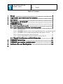
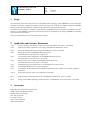
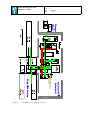
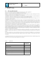
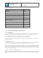
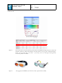
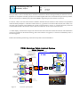
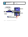
EUROPEAN SOUTHERN OBSERVATORY
Organisation Européenne pour des Recherches Astronomiques dans l’Hémisphere Austral
Europäische Organisation für astronomische Forschung in der südlichen Hemisphäre
VERY LARGE TELESCOPE
Prima Metrology Safety and Reliability Analysis
Doc. No VLT-TRE-ESO-15730-4546
Issue 1
Date 02/04/08
Prepared . .S.Leveque
..................................................................
Name
Date
Signature
Approved .F.Delplancke/M.Boecker
..................................................................
Name
Date
Signature
Released . .R.Gilmozzi
..................................................................
Name
Date
VLT PROGRAMME — TELEPHONE: (089) 3 20 06–0 — FAX: (089) 3 20 23 62
Signature
Prima Metrology Safety and
Reliability Analysis
Doc
Issue
Date
Page
VLT-TRE-ESO-15730-4546
1
02/04/08
1 of 23
Change Record
Issue / Rev.
Date
Section / Page. affected
1
02/04/08
all
Reason/Remarks
Prima Metrology Safety and
Reliability Analysis
Doc
Issue
Date
Page
VLT-TRE-ESO-15730-4546
1
02/04/08
2 of 23
Table of Contents
1
2
3
4
5
Scope .................................................................................. 3
Applicable and reference Documents ............................... 3
Acronyms ........................................................................... 3
Description of PRIMET ..................................................... 4
PRIMET Safety ................................................................. 8
5.1 List of possible hazards ............................................................ 8
5.2 Laser Hazards and Safety Interlock system ........................... 9
5.2.1 Introduction ................................................................... 9
5.2.2 PRIMET Laser source and specification for eye protection 9
5.2.3 PRIMET laser beam propagation and power levels .. 12
5.2.4 Protection against laser hazards ................................ 13
5.2.5 Laser Interlock system based on safety PLC’s ........... 14
5.3 Hazard Identification and Risk Estimation .......................... 20
6
7
8
9
PRIMET Reliability ......................................................... 21
PRIMET preventive maintenance .................................. 23
Actions after an Earthquake .......................................... 23
Prima Metrology Safety and
Reliability Analysis
1
Doc
Issue
Date
Page
VLT-TRE-ESO-15730-4546
1
02/04/08
3 of 23
Scope
This documents presents the safety analysis for the PRIMA Laser metrology system (PRIMET) as well as the implementation of the safety equipment required to operate it, based on AD 1 and AD 2. It addresses hazards to PRIMET
and to personnel during installation, commissioning, maintenance and operation at Paranal.
This document also includes an estimation of the reliability of PRIMET based on information provided by the manufacturers of some PRIMET components, based on the experience gained during the testing of PRIMET in Garching
and on other ESO instruments.
Preventive maintenance activities and a spare parts are listed.
2
Applicable and reference Documents
AD 1
Safety conformity assessment procedure, SAF-INS-ESO-00000-3444, issue 1, 10/10/2006
AD 2
ESO General Safety regulations, Laser safety, SAF-INS-ESO-00000-0011, Issue 1
AD 3
Electronic Design Specifications-SPE-ESO-10000-0015, issue 6, 8/12/2005
AD 4
Design Description of the PRIMA Metrology System,
VLT-TRE-ESO-15730-3000, Issue 1, March ‘03
AD 5
As built Phase Meter configuration for the PRIMA Metrology System,
VLT-TRE-IMT-15734-3726, issue 1, 20.7.2005.
AD 6
Design of the Laser Assembly of the PRIMA Metrology System,
VLT-TRE-IMT-15731-3154, issue 4, 19/12/2003.
AD 7
Prima Metrology Control Electronics, VLT-TRE-ESO-15735-2963, issue 2
AD 8
User Manual Mephisto Laser (www.innolight.de)
AD 9
User Manual: Diode-pumped Fiber-coupled Non planar Ring laser, Model 125-1319-200, Lightwave
Electronics.
AD 10
Prima Metrology Test report, VLT-TRE-ESO-15730-4042
RD 1
ESO Garching Laser Safety Instruction, SAF-PRO-ESO-00000-3511, issue 1,2/2/2006
RD 2
Design of the PRIMA Metrology Interlock System, VLT-TRE-ESO-15735-4544, issue 1 April 2008
3
Acronyms
MPE: Maximum permissible exposure limit
MTBF: Mean Time Between Failure
MTTR: Mean time to repair
N/A: Not Applicable
PV: Peak-to-Valley
TBC: To Be Confirmed
TBD: To Be Defined
Prima Metrology Safety and
Reliability Analysis
4
Doc
Issue
Date
Page
VLT-TRE-ESO-15730-4546
1
02/04/08
4 of 23
Description of PRIMET
The PRIMA Metrology System (PRIMET) is a component of the PRIMA facility, which monitor the internal optical
path of the VLTI using an Infrared laser.
The hardware is distributed in the VLTI storage room where the laser beams are generated inside an enclosure, and in
the VLTI laboratory where the laser beams are superimposed on the stellar paths. All the control electronics is located
inside the storage room.
The laser beams are transferred from the storage room to the VLTI laboratory using optical fibers. Once in the VLTI
laboratory the laser beams are collimated into 1 mm diameter beams and propagate in free space along the VLTI optical path up to the Star-separators of the UT’s or the AT’s, where they are retro-reflected.
Prima Metrology Safety and
Reliability Analysis
Figure 1
Doc
Issue
Date
Page
PRIMA Metrology hardware Overview
VLT-TRE-ESO-15730-4546
1
02/04/08
5 of 23
Prima Metrology Safety and
Reliability Analysis
VLTI Storage Room
MET Electronic Cabinets
Doc
Issue
Date
Page
VLT-TRE-ESO-15730-4546
1
02/04/08
6 of 23
PRIMA Metrology Table and enclosure
Light Source
Laser Assembly
-Laser Head
-Frequency Stabilization
ν
Heterodyne Assembly
-Fiber Coupler Unit
-AOM
ν -40MHz
ν -39.55MHz
ν+38.65MHz
ν+38MHz
Ch.B Ch.A
Beam Relay
Ch.A
Ch.B
probe
Quads
Beam Launcher &Combiner Unit Channel A
probe
FSU #A table
to Amber table
ref.
FSU#B_BC
ref.
Quads
Beam Launcher &Combiner Unit Channel B
FSU #B table
Interferometric Laboratory
to Midi table
optical fibers
VLTI Optical Train
Telescope’ Coude
End Point T1
Figure 2
End Point T2
End Point T2
End Point T1
PRIMA Metrology hardware Overview: green lines represents optical fibers; The red and blue
lines are free-space laser beams, superimposed on the stellar beams. ν=c/λ represents the frequency of the laser
electronic Cabinet#1:light source system
8x quadcell cables + actuator cables TBC
8xMM Fibers
IFC1#C2
Amber
Midi
PRIMA FSU#A
enclosure
Laser stabilization HW
Heterodyne assembly
IFOT#LAB
Optical table
IFC3#OT
Amber
Midi
PRIMA FSU#B
Doc
Issue
Date
Page
Cabinet#3
laser driver
8xSM-PM Fibers
IFIP#VLTI
LAN;TIM
Power; Cooling: SCP#31
IFCR#C1
Power; Cooling: SCP#31
LAN;TIM
Storage room (IC104)
Figure 3
IFC1#C3
IFIP#C3
IFCR#C3
Power:SCP#31
Interlock
Panel
VLTI LAB
Overview of the Metrology HW located in the Storage room (IC104). All Interface IFXX#XX are described in AD 7. The laser beams are
carried from the storage room (inside the enclosure) to the VLTI lab using optical fibers.
VLT-TRE-ESO-15730-4546
1
02/04/08
7 of 23
IFC1#OT
IFCR#C2
Prima Metrology Safety and
Reliability Analysis
electronic Cabinet#2:Phase meter system
IFC2#LAB
Prima Metrology Safety and
Reliability Analysis
5
Doc
Issue
Date
Page
VLT-TRE-ESO-15730-4546
1
02/04/08
8 of 23
PRIMET Safety
5.1
List of possible hazards
Table 1 lists the possible hazards following the classification given in AD 1 appendix C3.
However only a subset is applicable to PRIMET as indicated in Table 1.
PRIMET is considered free from mechanical hazards. There is no sharp edge and no injury or damage can occur by
unwanted activation of any motors. PRIMET has no moving parts.
All PRIMET components are rigidly attached to optical tables and secured against Eathquakes. The tables themselves
(storage room, VLTI lab) are bolted to the ground or equipped with Earthquake Restraints.
The electronic cabinets located in the storage room will be secured with steel cables fixed to the ceiling, as it is currently done for other instruments.
The PRIMET control electronics follows the rules of AD 3. It is using VLT standard components (LCU crate, boards,
cables etc...) or commercial components with CE marking. All cables are protected, properly secured and relayed
through cable trays. It follows the same approach as for any other VLTI Instrument already installed at Paranal. No
electrical safety issue is identified. Fiber connectors are all standard industrial FC/PC or FC/APC. All fibers cable are
routed inside special conduct (protection against mechanical damage).
During operation, no significant heat is produced inside the VLTI lab (only about 16 W produced by all 8 quadcells).
The heat produced inside the storage room is properly absorbed by the cooling system (see AD 7). All PRIMET temperature controlled components (I2 cell at 70 deg; SHG oven at 50 deg and laser driver) are protected by insulation
material (no skin burning possible) and are also protected against over heating. All cables are halogen free and fire
resistant. No thermal hazard is identified.
PRIMET is considered free from Hazard Generated by Materials and Substances. Only the heat exchangers of the
electronics cabinets (ESO standard ) are connected to cooling fluids provided by the Paranal Service Connection
Points.
The impact if Human error will be minimized by allowing access and operation of PRIMET only to trained people
who will also follow the ESO & Paranal safety regulation. Failure of power supply or control system will not cause
any hazard.
The PRIMET infrared laser source represents the major source of potential hazard. Section 5.2 details the origin of the
hazard as well as the associated safety equipment to be installed.
Table 1
Hazard List
Hazards List
Applicability
to PRIMET
Mechanical Hazards
NO
Electrical Hazards
NO
Thermal Hazards
NO
Hazard generated by Noise
NO
Hazard due to Vibration
NO
Hazard generated by Radiation
YES
Hazard Generated by Materials and Substances: Cooling
Liquid
NO
Prima Metrology Safety and
Reliability Analysis
Table 1
Doc
Issue
Date
Page
VLT-TRE-ESO-15730-4546
1
02/04/08
9 of 23
Hazard List
Hazard generated by Neglecting Ergonomic Principles
NO
Human Errors
YES
Hazards in conjunction with the deployment environment
NO
Combination of Hazards
NO
Unexpected Start-up
NO
Lack of opportunity to Stop/ Shut down in Optimum Position
NO
Variation in Rotational Speed
NO
Failure of Power Supplies
NO
Failure of Control System
NO
Errors of Fitting or Faulty Assembly
NO
Breakage during operation
NO
Falling or ejected Objects and Liquids
NO
Loss of Stability/ toppling over of machine
NO
Slipping, Tripping, Falling of persons
NO
5.2
5.2.1
Laser Hazards and Safety Interlock system
Introduction
Laser safety is part of the ESO general safety regulations documented in AD 2. This document defines the laser classification as well as the necessary controls (engineering, administrative, etc.) associated to their safe operation.
5.2.2
PRIMET Laser source and specification for eye protection
PRIMET operates one of the following Infrared laser (wavelength=1319 nm). Both laser have a fiber output which
confines the laser beam.
1/ Innolight laser (see AD 8)
According to its documentation, this laser complies with the Federal Register 21 CFR 1040.10 Laser Safety Standard.
and is CE marked.The maximum power at the output of its pigtailed fiber is 340 mW (λ=1319 nm)
2/ Also a spare laser is available in case of failure of the Innolight laser. The spare laser is a Lightwave laser 125 (see
AD 9). It is Class IIIb defined by the Federal register 21CFR 1040.10 and conforms to EN60825-1:1994. Standard for
safe use of lasers defined in ANSIZ136.1. This Laser is CE marked and the maximum power at the output of its pigtailed fiber is 210 mW (λ=1319 nm)
Both lasers corresponds to a class IIIb defined in AD 2.
Radiation in this class is very likely to be dangerous. For a continuous wave laser the maximum output into the eye
must not exceed 500mW. The radiation can be a hazard to the eye or skin. However, viewing of the diffuse reflection
is safe.
Doc
Issue
Date
Page
Prima Metrology Safety and
Reliability Analysis
VLT-TRE-ESO-15730-4546
1
02/04/08
10 of 23
Both lasers have an interlock input.
Based on AD 2, the following actions will be implemented:
•
The laser beam will be enclosed as much as possible
•
Signs and labels will be posted adequately
•
Controlled laser area will be defined, with access control and interlock triggering
•
Warning system will be implemented to notify when the laser is operated
•
The laser will only be operated by trained people
•
eyewear protectors will be available
Definition of the Eye protection level:
The method described in RD 1 p.32 is used to define the Eye protection level.
•
Determine the minimum laser beam diameter to which a person might be exposed under reasonably foreseeable circumstances: The worst case occurs when an operator looks directly at the tip of the fiber pigtailed
laser. The minimum laser beam diameter corresponds to the size of the eye pupil, i.e. d=0.7mm
•
Calculate the cross-sectional area of the beam at this point: a=π.d2/4=3.85e-5 m2
•
Calculate the average power density at this point by dividing the average power of the laser by the beam
area: For this, we take the maximum power level of P=0.35 W which leads to a density of D=0.35/ 3.85e-5
=9.1 e3 W/m2 < 1e4 W/m2
•
Look-up the required L number from table B1 in EN207: the required minimum L number is L3 (see Fig. 4):
Scale
number
EN207 – Classification and Specifications of filters and eye protection against Laser
Max spectral
Maximum power (E) and/or energy (H) density in the wavelength range
transmittance
180nm to 315nm
>315nm to 1400nm
>1400nm to 1000 microns
At Laser
D
I,R
M
D
I,R
M
D
I,R
M
Wavelength
W/m2
J/m2
W/m2
W/m2
J/m2
J/m2
W/m2
J/m2
W/m2
L1
L2
L3
L4
L5
L6
L7
L8
L9
L10
10-1
10-2
10-3
10-4
10-5
10-6
10-7
10-8
10-9
10-10
Figure 4
10-2
10-1
1
10
102
103
104
105
106
107
3x10²
3x10³
3x10⁴
3x10⁵
3x10⁶
3x10⁷
3x10⁸
3x10⁹
3x10¹⁰
3x10¹¹
3x10¹¹
3x10¹²
3x10¹³
3x10¹⁴
3x10¹⁵
3x10¹⁶
3x10¹⁷
3x10¹⁸
3x10¹⁹
3x10²⁰
102
103
104
105
106
107
108
109
1010
1011
5x10⁻²
5x10⁻¹
5
50
5x10²
5x10³
5x10⁴
5x10⁵
5x10⁶
5x10⁷
1.5x10⁻³
1.5x10⁻²
0.15
1.5
15
1.5x10²
1.5x10³
1.5x10⁴
1.5x10⁵
1.5x10⁶
104
105
106
107
108
109
1010
1011
1012
1013
103
104
105
106
107
108
109
1010
1011
1012
1012
1013
1014
1015
1016
1017
1018
1019
1020
1021
EN207, classification and specifications of filters and eye protection against Laser
Selected Laser Protection goggles
The protection goggles purchased for PRIMET are model “Protector (L-08)” and “All Star (L-02K)” with T96 filters,
from LaserVision (www.lvg.com). These goggles are specified L5, i.e much better than the minimum required (L3).
The Optical density is > 6 at 1319 nm. The glasses will be available in dedicated boxed at the entrance of all places
where operators are potentially in contact with the laser:
- Storage room
- VLTI laboratory
- All Coude rooms
Prima Metrology Safety and
Reliability Analysis
Doc
Issue
Date
Page
VLT-TRE-ESO-15730-4546
1
02/04/08
11 of 23
- Inside each AT
Figure 5
Filter T96 used on the safety Glasses purchased for the PRIMA Metrology:Protector (L-08) with
T96 filter;All Star (L-02K) with T96 filter from LaserVision (www.lvg.com); Aufbewahrungsbeh ä l t e r A u g e n s c h u t z ; R e f : 111 - 0 0 2 1 f ro m h t t p : / / d e . v w r. c o m / a p p / c a t a l o g / P ro d uct?article_number=111-0021
Figure 6
laser goggles for PRIMET; left: Protector (L-08); right: All Star (L-02K)
Doc
Issue
Date
Page
Prima Metrology Safety and
Reliability Analysis
5.2.3
VLT-TRE-ESO-15730-4546
1
02/04/08
12 of 23
PRIMET laser beam propagation and power levels
The PRIMET laser head is located inside an opaque metallic enclosure where part of the laser beam propagates in free
space (beam diameter 2 mm, max power=340x0.25=85 mW) for frequency stabilization purpose. The rest of the beam
is split in 4 and leave the enclosure through 4 optical fibers towards the VLTI lab.
Inside the VLTI lab the 4 x beams are collimated into 1 mm diameter beams, are superposed to the stellar beams and
propagates in free space along the VLTI optical train towards the Star separator of the telescopes (UTs or AT’s).
Each beam has a maximum power of 50 mW (whereas the power required during operation is only about 10 mW).
For the UT’s, the beams propagates in free space inside the Coude room where they are retroreflected back to the VLTI
laboratory and detected. However, less than half of the power is reflected by M9 and propagates through the VLT optical train up to the primary mirror of the UT (straylight). For the AT’s, the beams are confined inside the AT optical
train.
laser fiber
pigtailed
output fibers to VLTI lab
free space laser beam
inside the enclosure
Laser head
Figure 7
Table 2
View of the laser head and of the laser frequency stabilization system inside its enclosure. Inside
the enclosure, part of the laser beam propagates in free space (beam diameter <2 mm, max
power=340x0.25=85 mW. The laser beams leaving the enclosure are contained in optical fibers.
Laser beam propagation
Location
Max. free space
Laser power
Beam diameter
Storage Room
85 mW
2 mm
VLTI laboratory
50 mW
1 mm
VLTI Tunnel and light ducts
50 mW
4 mm
Coude AT’s/ UT’s
50 mW
4 mm
5.2.4
Protection against laser hazards
Definition of the protection foreseen against laser hazards
Storage Room
Controlled laser area with key-pad access control.
At the entrance door: Safety goggles available
Flashing light when the laser in ON
On the enclosure:
Warning labels.
The enclosure cannot be removed without tools.
VLTI laboratory
Controlled laser area with key-pad access control.
At the entrance door: Safety goggles available
Flashing light when the laser in ON
Interlock on the entrance door
The entrance door is the only access the VLTI laboratory and the VLTI tunnel.
The interlock can be overridden for several seconds using a pin code (both inside and outside the lab). A buzzer is available outside the lab to request opening of the door. A push button (+key) allows triggering and locking the interlock
VLTI Tunnel
Only accessible through the VLTI laboratory which makes the VLTI tunnel a Controlled laser area (with key-pad access
control)
Coude room UT’s
Controlled laser area with key-pad access control
At the entrance door (single access):
Safety goggles available
Flashing light when the laser in ON
Interlock on the entrance door
The interlock can be overridden for several seconds using a pin code (both inside and outside the lab). A buzzer is available outside the lab to request opening the door. A push button (+key) allows triggering and locking the interlock
Auxiliary telescope
At the entrance door (single access):
Warning labels
Safety goggles available
Auxiliary telescope pit (when no telescope is installed)
Warning labels on the pit cover
“do not remove “bi-lingual, english/spanish
Nasmyth platform
Warning labels.
Lock-out button available in the UT lock-out station
VLT-TRE-ESO-15730-4546
1
02/04/08
13 of 23
Protection foreseen
Doc
Issue
Date
Page
Location
Prima Metrology Safety and
Reliability Analysis
Table 3
Prima Metrology Safety and
Reliability Analysis
Doc
Issue
Date
Page
VLT-TRE-ESO-15730-4546
1
02/04/08
14 of 23
Any personnel with authorized access to the VLT area concerned by the PRIMET laser shall be trained by the Paranal
Safety officer in coordination with the supervisors responsible for the area. (VLTI storage room and laboratory, VLTI
tunnel, UT coude room, AT,UT Coude and azimuth/nasmyth platform).
Any operation using the PRIMET laser shall be performed in coordination with the VLT/VLTI managers.
During the Assembly, Integration and Verification phase of PRIMET, the Paranal safety officer will receive an extensive training related to the maintenance and operation of PRIMET.
Figure 8
5.2.5
Warning signs
Laser Interlock system based on safety PLC’s
All “Controlled laser area” defined Table 3 will be controlled by a Siemens safety PLC system. The system consists
of decentralized periphery modules with I/O connections (Simatic ET200S), connected in a star network to a CPU
(S7-317F). The CPU will control the interlock input of the laser driver. The system operates with Profinet distributed
via multimode fibers.
Each ET200S will guaranty access control and lock-out as described in the following figures.
The status of the laser (ON or OFF) will be indicated by a light at the entrance of all Controlled laser area. Access will
be granted by typing the right code on a key-pad. The interlock is then overridden for some seconds (delay adjustable)
to allow access to authorized people even if the laser is ON. Similarly, when going out of these areas without triggering
the laser interlock, a lock-out button must be pressed to override the interlock for some seconds. If someone enters the
lab/storage&coude rooms without entering the code (non-authorized persons), the interlock will be triggered and the
Doc
Issue
Date
Page
Prima Metrology Safety and
Reliability Analysis
VLT-TRE-ESO-15730-4546
1
02/04/08
15 of 23
laser goes OFF, or if it was already OFF, it cannot be switched ON without resetting manually the interlock. This configuration is compatible with daily operation in the lab/storage&coude rooms with authorized personnel. By default,
the laser will always be off during day-time unless PRIMA engineering activities must be carried out.
For the UT, a laser “lock-out” button will be available to interlock the laser whenever some work has to be performed
inside the Nasmyth adapter or inside the Coude structure (e.g operation on the mirrors M4, M5, M6, M7 or M8). This
new laser lock-out button will be added to the current Lock-out Station or close to it. It will be physically connected
to the ET200S located at the entrance of the coude room inside the “access control electronics box”.
A “status display” located in the storage room will show the status of the laser and of all interlocks. This information
will also be available on the Prima metrology GUI. If the interlock is triggered, we will know immediately where it
has been triggered.
Details about the design and wiring of the interlock system can be found in RD 2 .
Baseline: Star Network centered on the VLT Control Room
Access Control VLTI lab
VLTi Ante
Override &lock-out
Chamber IC108
Already existing fibers
Access Control
Override &Lock-out
ET200S
1x fiber pair XX m
Access Control
Override &Lock-out
ET200S
UT2
coude
Patch 1;UT2 NAP
-> VLT CR (Row C)
port 5-6(free ports=4)
UT2
NAP
Access Control
Override &Lock-out
VLT
Control
Room
Patch
1x fiber pair XXm
Patch 1;UT3 NAP
-> VLT CR (Row B)
port 7-8 (free ports=4)
UT3
coude
UT3
NAP
ET200S
\
1x fiber pair XXm
Access Control
Override &Lock-out
UT4
coude
UT4
NAP
\
ET200S
Figure 9
Patch 1;UT4 NAP
-> VLT CR (Row C)
Port 9-10 (free ports=5)
1x fiber pair XXm
Overview of the layout
VLTi
Control
Room
Patch
SCP
Patch
IC102
SCP32
IC104
ET200S
Storage
Room IC104
Access Control
storage room
Override &Lock-out
ET200S
Port 11,12
UT1
NAP
Port 11,12
Patch 1;1UT1 NAP
-> VLT CR (Row B)
port 5-6 (free ports=4)
Patch 2; VLT CR (Row A)
-> VLTi CR port 3-4 (free ports=3)
UT1
coude
1x copper Network cable, 50m
New fibers; length &
routing TBC
Laser
interlock
S7-317F
1x fiber pair
INTERLOCK MONITOR
Doc
Issue
Date
Page
Prima Metrology Safety and
Reliability Analysis
VLT-TRE-ESO-15730-4546
1
02/04/08
16 of 23
Override&Lock-out
Override and lockout Electronic box
Size 84x194x60mm
Buzzer
Magnetic Door
switch
overide switch
Lock-out button
Feedthrough
DOOR
Access Control ET200S +PSU+IO
PM-E F pp
4 DO
Light indicator Laser ON/OFF
IM 151-3PN HF
Buzzer
A
Buzzer switch (Entry request)
A
9
1
3
2
1
60
11
4
3
1
71
1
52
4
1
82
1
6
Media converter
5
6
3
7
A
4
A
8
Access control
Electronic box
Size 400x300x190
Access control Key pad
Lock-out button (UT lockout station, azimuth
platform)
1x fiber pair from UTX NAP
4
240V/XX A
Power
Figure 10
Safety equipment for the UT1,2,3,4 Coude rooms
Prima Metrology Safety and
Reliability Analysis
Doc
Issue
Date
Page
VLT-TRE-ESO-15730-4546
1
02/04/08
17 of 23
Override&Lock-out
Electronic box
Size 84x194x60mm
Magnetic Door
switch
Magnetic Door
switch
Buzzer
overide switch
Lock-out button
Feedthrough
Door 1
Door 2
PM -E F pp
4 DO
Light indicator Laser ON/OFF
IM 151-3PN HF
Buzzer
A
Buzzer switch (Entry request)
A
9
1
3
2
1
60
11
4
3
1
71
1
52
4
1
82
1
6
Media converter
5
6
3
7
A
4
A
8
Access control
Electronic box
Size 400x300x190
Access control Key pad
240V/XX A
Power
Figure 11
Copper
network cable
to storage
room
Safety equipment for the accessing the VLTI laboratory (IC108)
Doc
Issue
Date
Page
Prima Metrology Safety and
Reliability Analysis
Interlock Monitor Electronic box
Size 400x500x190
S7-317F ET200S +PSU+IO
PM-E F pp
Prima
Metrology
Laser
4 DO
IM 151-3PN HF
A
Status Display
A
9
VLT-TRE-ESO-15730-4546
1
02/04/08
18 of 23
1
3
2
1
60
11
4
3
1
71
1
52
4
1
82
1
6
5
6
3
7
A
4
A
8
Override&Lock-out
Electronic box
Size 84x194x60mm
240V/XX A
Power
Buzzer
Magnetic Door
switch
1xfiber pair to SCP32->VLT CR
overide switch
1xCopper network cable to VLTI Ante
Lock-out button
Chamber
Feedthrough
Buzzer
Buzzer switch (Entry request)
Access control
Electronic box
Size (TBC)
Access control Key pad
Figure 12
Safety equipment for the accessing the storage room (IC104)
10x LED Display
Figure 13
Display of the interlock Status
DOOR
Light indicator Laser ON/OFF
Prima Metrology Safety and
Reliability Analysis
Figure 14
Doc
Issue
Date
Page
VLT-TRE-ESO-15730-4546
1
02/04/08
19 of 23
Lock-out station located on the azimuth area of each UT where a new lock-out switch will be
installed to interlock the laser during work in the Nasmyth adaptor or in the Coude optical train
Prima Metrology Safety and
Reliability Analysis
5.3
Doc
Issue
Date
Page
VLT-TRE-ESO-15730-4546
1
02/04/08
20 of 23
Hazard Identification and Risk Estimation
The identification of the hazardous events and the estimation of the associated risks follows the Method provided in
AD 1.
The Hazard Severity Classification, the Hazard Occurrence Frequencies and the Hazard Risk Acceptance / Rejection
Matrix are defined in AD 1.
The analysis shows that hazard classification of PRIMET can be ranked Class III -tolerable risk (transport only) and
Class IV negligible risk (for all other phase of the project.
Under consideration of all hazards and protective measures, PRIMET can be used without any risk
Table 4
Risk estimation
Phase
Risk
Risk reduction
Hazard classification
Transport
-Hardware damaged
-Special Packing designed for
delicate instrumentation including shock recorders.
Marginal-Rare
Class III -tolerable risk
Integration
- Laser hazard
- Hardware damaged by
Human error
-Safety interlock to be integrated first.
-Integration performed by
trained people following the
ESO & Paranal safety regulation
Improbable-Marginal
Class IV negligible risk
Commissioning
- Laser hazard
- Hardware damaged by
Human error
- Safety interlock.
- Commissioning performed by
trained people following the
ESO & Paranal safety regulation
Improbable-Marginal
Class IV negligible risk
Operation
-Hardware damaged by
Human error
- No access to the Hardware
during operation
- User manual
Improbable-Marginal
Class IV negligible risk
Maintenance
- laser hazard
- Hardware damaged by
Human error
- Safety interlock
-Maintenance performed by
trained people following the
ESO & Paranal safety regulation
Improbable-Marginal
Class IV negligible risk
De-commissioning/Disposal
None
Not applicable
Not applicable
Doc
Issue
Date
Page
Prima Metrology Safety and
Reliability Analysis
6
VLT-TRE-ESO-15730-4546
1
02/04/08
21 of 23
PRIMET Reliability
The reliability goal of PRIMET is similar to any other VLTI instrument, i.e typically 12 month MTBF and a lifetime
of 10 years (87600 hours).
PRIMET will operate under well controlled laboratory conditions at Paranal:
- Temperature range: 15.5 ± 5 °C
- Relative Humidity: 5% to <50%
- Air cleanliness: class 30000.
The maximum duty of PRIMET is considered as 12 hours per nights during its 10 years lifetime, i.e a total of 43800
hours. However, in practice PRIMET will only be used during PRIMA runs which should occur typically by blocks
of 10 to 15 days and at most every month. So a more realistic duty is 12hoursx15daysx12monthx10years=21600
hours.
Preventive maintenance will be performed during day-time as well as any necessary replacement of components in
case of failure. Any component of PRIMET can be replaced in less than 8 hours (i.e. MTTR<8 hours), including
potential re-alignment, provided that a spare unit is available.
The most critical components of PRIMET are located inside the storage room and do not require access to the interferometric laboratory for repair.
Access to the laboratory will be only required if:
- a quadcell detector fails: two spares are available and MTTR< 2 hours
- a fiber transmitting the laser signals is damaged: spares available and already routed, see AD 7. The replacement by
a spare fiber is “instantaneous” but it then requires re-alignment as described below.
- the PRIMET optics must be re-aligned: MTTR< 8 hours. During the PRIMET testing in Garching, a re-alignment
was only necessary if a major intervention on the FSU optics had occurred. The stability of the PRIMET beam injection/extraction opto-mechanics is such that no re-alignment is necessary at a scale of several months.
The list of components with potential failure are listed below. It includes the PRIMET electronic parts and active components. Excluded are all passive mechanical structures and optics for which no “failure” are expected during the lifetime of PRIMET, considering the above environmental conditions.
Table 5
Component Reliability
Item
MTBF
(hours)
Duty at
Paranal
(hours)
Spares available/Comments
ESO LCU crate
>100000
87600
spares available
ESO standard boards used in PRIMET
CPU 6100
87600
>320 000
87600
Doc
Issue
Date
Page
Prima Metrology Safety and
Reliability Analysis
Table 5
VLT-TRE-ESO-15730-4546
1
02/04/08
22 of 23
Component Reliability
M58 DIO
70 000
87600
M36 AIO
44 000
87600
-
87600
ISER12
VMIVME -3123 (AI)
>63 000
87600
MPV955 (AO)
>63 000
87600
High speed digital I/O
PMC-HPDI32A-64K
145 000
87600
Reflective memory
VMIPMC-5565-110000
> 400 000
87600
(1 spare)
(1 spare)
Phase Meter
-
21600
Custom item. 1 spare
Proto manufactured in 2001
still operating without failure
Current Phase meter (x2)
manufactured in 2005. Only
1 failure reported (“OR”
gate replaced)
Laser head
10 000
21600
10000 hours=lifetime of the
pump diodes
1 spare
Optical fibers and adaptors
>87600
87600
spares available
Fiber coupler
-
87600
operated since end of 2002
without failure.
1 spare
AOM
Driver
-
21600
1 spare.
Operated since 2004
1 failure observed.
No failure observed on a
similar system since 2001
AOM heads
-
21600
No Spare (cost reason,
TBC)
Operated since 2004
No failure observed on a
similar system since 2001
-
21600
Custom
2 spares
Quadcell (detector head + analog
module)
Laser frequency stabilization Hardware
Operated since mid-2004
without failure
SHG crystal and oven
-
21600
EOM and driver
-
21600
1 spare
Doc
Issue
Date
Page
Prima Metrology Safety and
Reliability Analysis
Table 5
VLT-TRE-ESO-15730-4546
1
02/04/08
23 of 23
Component Reliability
iodine cell
-
21600
2 spares
Lock-in amplifier
-
21600
“standard” electronics
Temperature controller/detector power
supply
-
21600
“standard” electronics
detector
-
21600
1 spare
7
PRIMET preventive maintenance
Table 6
PRIMET Preventive maintenance
Item
manpower
required
Total time
required
Period
Cleaning of the PRIMET optics
1 pers.
2 days
5 years
Check Alignment
1 pers
1/2 day
every PRIMA run or every 2
months
Change/clean fiber adaptors and
fibers
1 pers
1/2 hour
every change of Channel A of
PRIMA
Run health Check script
1 pers
1/2 day
every PRIMA run or every
month
Check Laser Interlock System
2 pers
1/2 day
every year
8
Actions after an Earthquake
After an earthquake of medium intensity (Mercali intensity 4-5 ) or high intensity (Mercali intensity >5), the hardware
located in the storage room and in the VLTI laboratory shall be inspected . This includes in particular:
•
Checking that the cooling pipes of the heat exchangers located on each electronic cabinet are OK.
•
Checking that the safety Interlock system is operational
In addition, some software scripts dedicated to health checks shall be run.