1
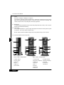
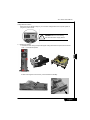
S17 Series User's Manual
Preface
Thank you for purchasing and adopting the S17 Series as your favorite computer product.
To assure the safe application of this product, please carefully read the following:
v Please strictly follow the labeled warnings and instructions given.
v Before disassembling or cleaning this product, make sure the power connector is
unplugged.
v Never wipe the interior of the system with water or dip the system in water.
v Before connecting to any peripheral, please turn off the power of the system.
v Ensure that the voltage select switch is in the correct position for the type of voltage
you use(115V/230V).
Apr /2003
1
■ Features
S17 Series adopts the motherboard designed and developed for Customer which
allows you to work seamlessly with the Windows operating system.
The nimble design of the book size casing not only gives convenient assembling and
maintenance but also allows you to easily upgrade in the future!
WARNING
If the battery is not properly handled, there may be a risk
of explosion; make sure you are using the same or
equivalent battery. Please dispose the used battery
according to the instructions given by the manufacturer.
English
S17 Series User's Manual
■ Specifications
-Product Specifications
-Book Size Chassis
-Small Form factor (Refer to the model specification)
-Power Supply
-DVD-ROM / CD-ROM (Option)
-Power Cord
-CPU Cooler (Option)
-Keyboard (Option)
-Accessory Box Content
System Installation Guide
Screw Bag
Driver CD
Mouse (Option)
foot atand
■ Items included in the package
Pow er Cord
2
*CPU c ooler
(Option)
PC
*Keyboard
(Option)
Softw ard and
Manuals
*Foot Stand
(Option)
*Mouse
(Option)
M Specification w ith “Option” are s ubject to change w ithout notice.
English
S17 Series User's Manual
I.
Chassis
Dimensions 359(D)mm x 88(W)mm x 275(H)mm
This chassis is made with material complied with UL specification and designed for space saving
and it can be opened esaily with thumbscrew. There are one 5.25” and one 3.5” drive bays. This
chassis complies with corresponding EMC and safety regulations.
II.
Motherboard
This Motherboard is Standard Product,it will be setup ready before ship out,So you do’nt need to
change for this Motherboard setting.
III. Power Supply
This computer adopts a S.F.X. power supply and supports the functions of turning off the system
by software. The factory default voltage is 230V.
MNote: Please confirm the default voltage of the country before turning on the computer.
IV. Front Panel and Rear Panel Components
( P3 Solution)
( P4 Solution)
3
Front Panel Components
Rear Panel Components
1.Optical Device
2.Power Button
3.Audio Out
4.MIC In
5.USB Hub
6.Foot Stand
1.Power Switch
9.Voltage Switch
2.Keyboard Port(PS/2) 10.Mouse Portt(PS/2)
3.COM Port
11.LPT Port
4.VGA Port
12.Game Port
5.MIC In
13.LAN Port
6.Audio In
7.Audio Out
8.USB Hub
English
S17 Series User's Manual
Voltage Selection Switch
Select the correct voltage setting for your local area voltage before the computer system is
plug to the power source.
!
WARNING:Select incorrect setting
will cause the Power supply failure!
V. Installing the System
1. Unscrew the rear casing and push the upper casing toward the front panel,and loose the
hook to leval the front panel.
4
2. After loosening the 3 front screws, pull out the Device disk Bay.
English
S17 Series User's Manual
3. Put the hard disk drive into the rack and align the screws at the screw holes.
4. CPU
4-1. Place the CPU into the CPU socket on the motherboard. Make sure that you have lifted the
transversal lever and aligned the aslant side of the CPU along the aslant side of the CPU
socket.
4-2. After CPU is secured tightly onto the CPU socket, release the transversal lever and attach
it to the CPU socket.
5
4-3. Evenly spread the heat dispersion paste on the CPU and make sure it totally covers the
CPU. The CPU fan must be tightly attached on the CPU to maximize the effect of heat
dispersion.
4-4. Connect fan power connector to CPU FAN on the motherboard.
A. For Intel® Pentium® III and Intel® Celeron® processors
CPU Pin
Pull the transversal lever
Evenly spread the heat
dispersion paste on the CPU
Latch the hooks on
both sides of the CPU
securely into the CPU
socket
Fix the cooler on the rack.
English
S17 Series User's Manual
B. For Intel® Pentium® 4 processors
CPU Pin
Pull the transversal lever
Evenly spread the heat
dispersion paste on the CPU
6
Fix the cooler on the rack.
5. Memory
This section introduces the memory installation. When the memory is installed, the direction of the
foolproof groove should be the same as that of the memory slot on the motherboard. The hooks on
both sides must be latched completely for a correct installation.
There are fixing grooves on both sides
SDRAM
Make sure the direction of the foolproof groove must be the same as that of the
memory slot on the motherboard.
English
S17 Series User's Manual
There are fixing grooves on both sides
DDR
Make sure the direction of the foolproof groove must be the same as that of the
memory slot on the motherboard.
Fixing the hooks. The hooks must be fixed into the grooves
before the installation is considered complete.
7
6. Connect the IDE bus cable bundled in the accessory kit. Connect the black connector to the
hard disk drive and align the first pin of the red cable to Pin 1 labeled on the hard disk.
7. Connect the connector of the power supply to the power supply socket of the hard disk drive.
Put the Device Disk Bay
into the chassis.
Alightle 3 screws at the screw
holes.
Location the HDD Cable into the
Cable hook.
English