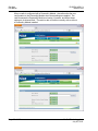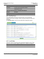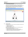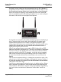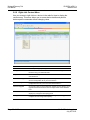
1
RLXIB-ICN 802.11n Industrial Client July 25, 2013 USER MANUAL Your Feedback Please We always want you to feel that you made the right decision to use our products. If you have suggestions, comments, compliments or complaints about our products, documentation, or support, please write or call us. ProSoft Technology 5201 Truxtun Ave., 3rd Floor Bakersfield, CA 93309 +1 (661) 716-5100 +1 (661) 716-5101 (Fax) www.prosoft-technology.com [email protected] Copyright © 2013 ProSoft Technology, Inc., all rights reserved. RLXIB-ICN User Manual July 25, 2013 ® ® ® ® ® ProSoft Technology , ProLinx , inRAx , ProTalk , and RadioLinx are Registered Trademarks of ProSoft Technology, Inc. All other brand or product names are or may be trademarks of, and are used to identify products and services of, their respective owners. In an effort to conserve paper, ProSoft Technology no longer includes printed manuals with our product shipments. User Manuals, Datasheets, Sample Ladder Files, and Configuration Files are provided on the enclosed DVD and are available at no charge from our web site: http://www.prosoft-technology.com Important Safety Information The following Information and warnings pertaining to the radio module must be heeded. WARNING – EXPLOSION HAZARD – DO NOT REPLACE ANTENNAS UNLESS POWER HAS BEEN SWITCHED OFF OR THE AREA IS KNOWN TO BE NON-HAZARDOUS. "THIS DEVICE CONTAINS A TRANSMITTER MODULE, FCC ID: . PLEASE SEE FCC ID LABEL ON BACK OF DEVICE." "THIS DEVICE USES AN INTERNAL COMPACT FLASH RADIO MODULE AS THE PRIMARY RADIO COMPONENT. THE COMPACT FLASH RADIO MODULE DOES NOT HAVE AN FCC ID LABEL. THE COMPACT FLASH RADIO MODULE HAS NO USER SERVICEABLE PARTS." "THIS DEVICE COMPLIES WITH PART 15 OF THE FCC RULES. OPERATION IS SUBJECT TO THE FOLLOWING TWO CONDITIONS: (1) THIS DEVICE MAY NOT CAUSE HARMFUL INTERFERENCE, AND (2) THIS DEVICE MUST ACCEPT ANY INTERFERENCE RECEIVED, INCLUDING INTERFERENCE THAT MAY CAUSE UNDESIRED OPERATION." "CHANGES OR MODIFICATIONS NOT EXPRESSLY APPROVED BY THE PARTY RESPONSIBLE FOR COMPLIANCE COULD VOID THE USER’s AUTHORITY TO OPERATE THE EQUIPMENT." Industry Canada Requirements "THIS DEVICE HAS BEEN DESIGNED TO OPERATE WITH AN ANTENNA HAVING A MAXIMUM GAIN OF 24 dB. AN ANTENNA HAVING A HIGHER GAIN IS STRICTLY PROHIBITED PER REGULATIONS OF INDUSTRY CANADA. THE REQUIRED ANTENNA IMPEDANCE IS 50 OHMS." "TO REDUCE POTENTIAL RADIO INTERFERENCE TO OTHER USERS, THE ANTENNA TYPE AND ITS GAIN SHOULD BE CHOSEN SUCH THAT THE EQUIVALENT ISOTROPICALLY RADIATED POWER (EIRP) IS NOT MORE THAN THAT REQUIRED FOR SUCCESSFUL COMMUNICATION." "THE INSTALLER OF THIS RADIO EQUIPMENT MUST INSURE THAT THE ANTENNA IS LOCATED OR POINTED SUCH THAT IT DOES NOT EMIT RF FIELD IN EXCESS OF HEALTH CANADA LIMITS FOR THE GENERAL POPULATION; CONSULT SAFETY CODE 6, OBTAINABLE FROM HEALTH CANADA." Agency Approvals and Certifications Wireless Approvals Visit our web site at www.prosoft-technology.com for current wireless approval information. Hazardous Locations ANSI/ISA 12.12.01 Groups A, B, C, D UL/cUL C22.2 No. 213-M1987 ATEX EN60079-0 and EN60079-15 Ordinary Locations CSA/CB EN60950 N. America & W. Europe FCC/IC Part 15, Class A and ICES-003 ETSI ETSI EN300 328 and ETSI EN301 893 Recommended Antennas Part Number Max Gain Part number Max gain Part Number Max gain A2503S6-O 3 dBi A2406S3-DP 6 dBi A5017NJ3-DP 17 dBi A2408NJ-DP 8 dBi A2419NJ-DP 19 dBi A5024NJ-DP 24 dBi A2506NJ6-0 6 dBi A2503S6-O 3 dBi A2412NJ3-DP 12 dBi A5007S3-DP 7 dBi A2415NJ-OC 15 dBi A082503-80-OBH 3 dBi A2402S-OS 2 dBi A2402S-OSLP 2 dBi A2403NBH-OC 3 dBi A2404NBHW-OC 4 dBi A2404NJ-OC 4 dBi A2405S-OA 5 dBi A2405S-OM 5 dBi A2405S-OS 5 dBi A2406NJ-OC 6 dBi A2406NJ-OCD 6 dBi A2408NJ-OC 8 dBi A2409NJ-OCD 9 dBi A2502S-OA 2 dBi A2504S-OA 4 dBi A2506NJ-OC 6 dBi A5003S-OBH 3 dBi A5006NJ-OC 6 dBi A5009NJ-OC 9 dBi A2508NJ-DP 8 dBi A2413NJ-DP 13 dBi A2416NJ-DS 16 dBi A5019NJ-DP 19 dBi A2419NJ-DB 19 dBi A2424NJ-DB 24 dBi A5829NJ-DB 29 dBi A2410NJ-DY 10 dBi A2415NJ-DY 15 dBi A5812NJ-OC 12 dBi Antenna spacing requirements for user safety It is important to keep the radio's antenna a safe distance from the user. To meet the requirements of FCC part 2.1091 for radio frequency radiation exposure, this radio must be used in such a way as to guarantee at least 20 cm between the antenna and users. Greater distances are required for high-gain antennas. The FCC requires a minimum distance of 1 mW *cm2 power density from the user (or 20 cm, whichever is greater). If a specific application requires proximity of less than 20 cm, the application must be approved through the FCC for compliance to part 2.1093. RLXIB: CSA C22.2 213-M1987 and N. American Standard ANSI/ISA 12.12.01 listing In accordance with Canadian Standard CSA C22.2 213-M1987 and ANSI Standard ISA 12.12.01, the RLXIB series radios have been UL listed for operation in Class I, Division 2, Groups A, B, C, and D Locations. This equipment is suitable for use in Class I, Division 2, Groups A, B, C and D OR non-hazardous locations only. WARNING – EXPLOSION HAZARD – Do not disconnect equipment unless power has been removed or the area is known to be non-hazardous. WARNING – EXPLOSION HAZARD - Substitution of any components may impair suitability for Class I, Division 2. Power must be provided from a Limited Power Source. AVERRTISSEMENT - RISQUE D'EXPLOSION - LA SUBSTITUTION DE COMPOSANTS PEUT RENDRE CE MATERIEL INACCEPTABLE POUR LES EMPLACEMENTS DE CLASSE I, DIVISION 2. AVERRTISSEMENT - RISQUE D'EXPLOSION - AVANT DE DECONNECTER L'EQUIPEMENT, COUPER LE COURANT OU S'ASSURER QUE L'EMPLACEMENT EST DESIGNE NON DANGERUEX. The following label is applied to the radio to indicate that it is listed under ANSI/ISA standard 12.12.01 and CSA standard C22.2 213-M1987. This Device contains a Radio Transmitter Module FCC ID: Canada IC: Conforms to ANSI/ISA Std. 12.12.01 – Certified to CSA Std. C22.2 No. 213-M1987 Class I Division 2 10-24 Volts dc 6 Watts 48 Volts dc using the PoE Injector Groups A, B, C & D Max. Ambient: 60ºC ATEX Approval II 3 G Ex nA nL IIC X -30° C <= Ta <= 60° C ProSoft Technology, Inc., Bakersfield, CA USA Model: RLXIB S/N: XXXXXXXXXX Caution: Read instructions before operating in Hazardous Areas N. America All RLXIB 802.11n radios must be installed inside an IP54 enclosure which requires a special tool for access; except the RLXIB-IH2N-W, which is made so that no special enclosure is required for this specific model. Explosive Atmosphere Power, Input, and Output (I/O) wiring must be in accordance with the authority having jurisdiction A Warning – Explosion Hazard – Do not make or break connections in an explosive atmosphere. B Caution – Use only approved recommended power supply. C Warning - Power supply should be installed in a non-hazardous area. D Warning – DO NOT OPEN WHEN ENERGIZED. E These products are intended to be mounted in an IP54 enclosure. The devices shall provide external means to prevent the rated voltage being exceeded by transient disturbances of more than 40%. This device must be used only with ATEX certified backplanes. United States FCC & Industry Canada rules Note: This equipment has been tested and found to comply with the limits for a Class A digital device, pursuant to Part 15 of the FCC Rules. These limits are designed to provide reasonable protection against harmful interference when the equipment is operated in a commercial environment. This equipment generates, uses, and can radiate radio frequency energy and, if not installed and used in accordance with the instruction manual, may cause harmful interference to radio communications. Operation of this equipment in a residential area is likely to cause harmful interference in which case the user will be required to correct the interference at his own expense. This device complies with Part 15 of the FCC Rules. Operation is subject to the following two conditions: The device may not cause harmful interference, and it must accept any interference received, including interference that may cause undesired operation. This Class A digital apparatus complies with Canadian ICES-003. Cet appareil numérique de la classe A est conforme à la norme NMB-003 du Canada. CAUTION: Changes or modifications not expressly approved by the manufacturer could void the user’s authority to operate the equipment. European CE certification The radio modem has been approved for operation under the RTT&E directive, passing the following tests: ETS300826 (EMC), ETS300-328 (Functionality), and EN60950 (Safety). The following is the appropriate label that is applied to the radio modem product line to indicate the unit is approved to operate with CE certification: The following is the appropriate label that is applied to the radio modem product line shipping package to indicate the unit is approved to operate with CE certification: AUS B DK FIN F D GR IRE I LUX NL P E S UK Note: Member states in the EU with restrictive use for this device are crossed out. This device is also authorized for use in all EFTA member states (CH, ICE, LI, and NOR). EU Requirements 1. For outdoor use, France has a frequency restriction of 2.4 GHz to 2.454 GHz for an output power greater than 10 mW and below 100 mW. 2. For outdoor use in France, the output power is restricted to 10 mW in the frequency range of 2.454 GHz to 2.4835 GHz. 3. 5.15 GHz to 5.35 GHz is restricted to 200 mW EIRP throughout the European Union. Power Supply and Accessories Warning The certifications listed in this document apply to only the radio mentioned herein. These certifications do not extend to any other items, including accessories or any external means of supplying power to the radio. Accessories and power supplies shipped with the radio have not been tested and are not covered by these certifications. Any noncertified items added to the radio, including any means of supplying power, must be located in an area known to be non-hazardous. All wiring to and from the Power-over-Ethernet (PoE) injector supplied with the radio must be routed and installed inside the building or plant and never routed or installed outside of the building or plant. RLXIB-ICN ♦ 802.11n Industrial Client Contents User Manual Contents Your Feedback Please ........................................................................................................................ 2 Important Safety Information ............................................................................................................... 2 Agency Approvals and Certifications .................................................................................................. 3 Recommended Antennas ................................................................................................................... 3 Antenna spacing requirements for user safety ................................................................................... 3 RLXIB: CSA C22.2 213-M1987 and N. American Standard ANSI/ISA 12.12.01 listing ..................... 4 ATEX Approval.................................................................................................................................... 4 United States FCC & Industry Canada rules ...................................................................................... 5 European CE certification ................................................................................................................... 5 EU Requirements ................................................................................................................................ 5 Power Supply and Accessories Warning ............................................................................................ 5 1 Start Here ® 1.1 1.1.1 1.1.2 1.2 1.3 1.4 1.5 1.6 1.6.1 1.6.2 1.6.3 1.7 1.7.1 1.7.2 1.7.3 1.7.4 1.7.5 1.7.6 1.7.7 1.7.8 1.7.9 1.8 2 11 About the RadioLinx RLXIB-ICN ........................................................................... 11 Radio Specifications ................................................................................................ 11 Agency Approvals & Certifications .......................................................................... 13 Package Contents ................................................................................................... 13 System Requirements ............................................................................................. 13 Install the WirelessN Discovery Tool ....................................................................... 14 Install ProSoft Wireless Designer ............................................................................ 15 Planning the Network .............................................................................................. 15 Installation Questions .............................................................................................. 16 ProSoft Wireless Designer ...................................................................................... 16 Planning the Physical Installation ............................................................................ 17 Configuring the Radios ............................................................................................ 17 Start WirelessN Discovery Tool .............................................................................. 18 Personality Module .................................................................................................. 19 Plug In the Cables ................................................................................................... 21 Detecting the Radio ................................................................................................. 22 Assign an IP Address .............................................................................................. 22 Set up the Client Radio ........................................................................................... 23 Save the Radio Configuration ................................................................................. 26 Set the Date and Time ............................................................................................ 27 Adding and Configuring Additional Client Radios ................................................... 27 Verify Communication ............................................................................................. 28 Installing the Radios 2.1 2.1.1 2.2 3 Connecting antennas .............................................................................................. 30 Using Multiple Antennas (MIMO) ............................................................................ 31 Testing the Network Installation Plan ...................................................................... 31 Diagnostics and Troubleshooting 3.1 3.2 3.3 3.4 ProSoft Technology, Inc. July 25, 2013 29 33 Diagnostics .............................................................................................................. 33 Check the Ethernet cable ........................................................................................ 34 LED Display ............................................................................................................. 34 Retrieve the Default Password ................................................................................ 34 Page 7 of 129 Contents User Manual RLXIB-ICN ♦ 802.11n Industrial Client 3.5 3.6 3.6.1 4 Troubleshoot missing radios ................................................................................... 35 Improving Signal Quality ......................................................................................... 35 Understanding Signal to Noise Ratio ...................................................................... 36 RadioLinx Configuration Manager 4.1 4.1.1 4.1.2 4.2 4.2.1 4.2.2 4.2.3 4.2.4 4.2.5 4.2.6 4.2.7 4.2.8 4.3 4.3.1 4.3.2 4.3.3 4.3.4 4.3.5 4.3.6 4.4 4.4.1 4.4.2 4.4.3 4.4.4 4.4.5 4.4.6 5 Login ....................................................................................................................... 39 Login User Name and Password ............................................................................ 39 Session Timeout ..................................................................................................... 40 Configuration........................................................................................................... 40 Overall ..................................................................................................................... 40 Radio 1 or Radio 2 .................................................................................................. 42 IPv6 Configuration .................................................................................................. 45 Radio Configuration ................................................................................................ 46 Security Configuration ............................................................................................ 48 Parent Selection ..................................................................................................... 49 Access Configuration .............................................................................................. 54 SNMP Configuration ............................................................................................... 55 Diagnostics ............................................................................................................. 59 Radio 1 Status ........................................................................................................ 59 Address Table ......................................................................................................... 60 Statistics .................................................................................................................. 60 Child Links .............................................................................................................. 61 802.11 Traffic .......................................................................................................... 62 Tools ....................................................................................................................... 63 Utilities .................................................................................................................... 66 Saving and Restoring Settings ............................................................................... 66 Factory Reset.......................................................................................................... 70 Rebooting the Radio ............................................................................................... 73 Upload ..................................................................................................................... 74 View Event Logs ..................................................................................................... 78 Logs Settings .......................................................................................................... 78 WirelessN Discovery Tool 5.1 5.2 5.3 5.4 5.5 5.6 5.7 5.8 5.9 5.9.1 5.9.2 5.9.3 5.9.4 5.9.5 5.9.6 5.10 5.10.1 5.10.2 Page 8 of 129 37 81 View the List of Detected Radios ............................................................................ 82 View Radio Network Diagram(s)............................................................................. 83 Configure Radios .................................................................................................... 83 Scan the Network ................................................................................................... 84 Save and Load Snapshots ...................................................................................... 84 Event Log ................................................................................................................ 85 Firewall Requirements ............................................................................................ 85 Radio List ................................................................................................................ 86 Topology View ........................................................................................................ 87 Display tools............................................................................................................ 89 View Radio Details .................................................................................................. 90 Download Radio Settings ....................................................................................... 90 Upload Radio Settings ............................................................................................ 91 Upgrade Radio Firmware ........................................................................................ 91 Right click Context Menu ........................................................................................ 92 Radio Detailed View ............................................................................................... 93 Summary................................................................................................................. 93 Radio # .................................................................................................................... 94 ProSoft Technology, Inc. July 25, 2013 RLXIB-ICN ♦ 802.11n Industrial Client 5.10.3 5.10.4 5.11 5.11.1 5.11.2 5.11.3 5.11.4 5.11.5 6 Ethernet Devices ..................................................................................................... 96 Bridges .................................................................................................................... 97 Discovery Tool Menus and Toolbars ....................................................................... 98 File Menu ................................................................................................................. 98 Scan Menu .............................................................................................................. 98 View Menu ............................................................................................................... 99 Help Menu ............................................................................................................. 100 Toolbars................................................................................................................. 100 Reference 6.1 6.2 6.2.1 6.2.2 6.2.3 6.3 6.3.1 6.3.2 6.3.3 6.3.4 6.3.5 6.3.6 6.3.7 6.3.8 7 Contents User Manual 103 Product Overview .................................................................................................. 103 Radio hardware ..................................................................................................... 104 Radio Power Requirements .................................................................................. 104 Ethernet Cable Specifications ............................................................................... 105 Ethernet Cable Configuration ................................................................................ 105 Antennas ............................................................................................................... 106 Antenna Pattern .................................................................................................... 106 Antenna Gain ........................................................................................................ 107 Antenna Polarity .................................................................................................... 107 Whip antennas ...................................................................................................... 108 Collinear array antennas ....................................................................................... 108 Yagi Array Antenna ............................................................................................... 109 Parabolic reflector antennas ................................................................................. 109 Antenna location, spacing, and mounting ............................................................. 110 Support, Service & Warranty 111 Contacting Technical Support ......................................................................................................... 111 7.1 Warranty Information ............................................................................................. 112 8 Glossary of Terms Index ProSoft Technology, Inc. July 25, 2013 113 127 Page 9 of 129 RLXIB-ICN ♦ 802.11n Industrial Client ProSoft Technology, Inc. July 25, 2013 User Manual Page 10 of 129 RLXIB-ICN ♦ 802.11n Industrial Client 1 Start Here User Manual Start Here In This Chapter ® About the RadioLinx RLXIB-ICN .......................................................... 11 Package Contents ................................................................................. 13 System Requirements ........................................................................... 13 Install the WirelessN Discovery Tool ..................................................... 14 Install ProSoft Wireless Designer .......................................................... 15 Planning the Network ............................................................................ 15 Configuring the Radios .......................................................................... 17 Verify Communication ........................................................................... 28 For most applications, the installation and configuration steps described in the following topics will work without additional programming. ProSoft Technology strongly recommends that you complete the steps in this chapter before developing a custom application. 1.1 About the RadioLinx® RLXIB-ICN The RadioLinx 802.11n Industrial Hotspot series provides enterprise-class technology, optimized for rugged industrial performance and easy deployment in the field. These 802.11n Hotspots use multiple-input/multiple-output (MIMO) technology supporting up to 3 antennas. This allows fast data rates up to 300Mbps with EtherNet/IP Requested Packet Interval (RPI) times as low as 2 ms. The Industrial Client (RLXIB-ICN) provides connectivity to any third-party Access Point. It is also compatible with RadioLinx 802.11a/b/g radios. More than just a new 802.11 technology, the RLXIB-IHN family adds RADIUS security for centralized management of security policies, VLANs for network traffic segmentation, and data prioritization while continuing to include the industrial wireless features that have made previous Industrial Hotspots successful. 1.1.1 Radio Specifications Frequency Band Frequency Channel (Varies by country) 2.412GHz to 2.462GHz (FCC) 2.412GHz to 2.472GHz (ETSI) 1-11 1-13 ProSoft Technology, Inc. July 25, 2013 Page 11 of 129 Start Here User Manual RLXIB-ICN ♦ 802.11n Industrial Client Frequency Band Frequency Channel 5.150 GHz to 5.250 GHz (FCC/ETSI) 1 5.250 GHz to 5.350 GHz (ETSI) 1 5.470 GHz to 5.580 GHz (ETSI) 1 5.680 GHz to 5.700 GHz (ETSI) 5.725 GHz to 5.850 GHz (FCC) 1 FCC Pending 36 - 48 52 - 64 100 - 116 136 - 140 149 - 165 Standards 802.11n, 802.11a & 802.11g (Legacy) 802.11h (DFS), 802.11i (RADIUS), 802.11e (QoS) 802.1Q (VLAN), 802.3af (PoE), IGMPv2 Transmit Power (Programmable) *Subject to Regional Regulatory Limits 22 dBm @ MCS0, MCS8 (802.11an/gn) 17 dBm @ MCS7, MCS15 (802.11an/gn) 22 dBm @ 6 Mbps (802.11a/g) 17 dBm @ 54 Mbps (802.11a/g) Antenna Impact: 3 Antennas/ MIMO: Use values above 2 Antennas: Subtract 3 dB from values above 1 Antenna: Subtract 5 dB from values above Channel data rates (802.11n) MCS0 – MCS15, 1-2 Channels & 1-2 Streams 1 Channel 2 Channels Rate Streams 7 Mbps 15 Mbps MCS0 1 Stream 72 Mbps 150 Mbps MCS7 14 Mbps 30 Mbps MCS8 144 Mbps 300 Mbps MCS15 2 Streams Channel data rates (802.11a/g) 802.11a/g: 54, 48, 36, 24, 18, 12, 9, 6 Mbps Receiver Sensitivity (Typical) -92 dBm @ MCS0, MCS8 (802.11an/gn) -70 dBm @ MCS7, MCS15 (802.11an) -74 dBm @ MCS7, MCS15 (802.11gn) -92 dBm @ 6 Mbps (802.11an/gn) -74 dBm @ 54 Mbps (802.11a) -78 dBm @ 54 Mbps (802.11g) Security WPA2 Enterprise – 802.11i AES w/ RADIUS WPA2 Personal – 802.11i AES w/ Passphrase Legacy WPA TKIP, WEP support & MAC ID filter Physical Enclosure Extruded aluminum with DIN and panel mount Size 115 x 117 x 45 mm (W x H x D) 4.5 x 4.6 x 1.75 inches Vibration IEC 60068 2-6 (20g, 3-Axis) Shock IEC 60068 2-27 (5g, 10Hz to 150Hz) Ethernet Ports One 10/100 Base-T connector, shielded RJ45 Antenna Port (3) RP-SMA connector Personality Module Industrial SD Memory Module Weight 1.1 lbs (499g) Environmental Operating Temperature Page 12 of 129 -40° C to +75° C ProSoft Technology, Inc. July 25, 2013 RLXIB-ICN ♦ 802.11n Industrial Client Start Here User Manual Humidity Up to 100% RH, without condensation External Power PoE Injector 10Vdc to 24 Vdc 802.3af PoE Powered Device Average Power <9W 1.1.2 Agency Approvals & Certifications Wireless Approvals Visit our web site at www.prosoft-technology.com for current wireless approval information. Hazardous Locations ANSI/ISA 12.12.01 groups A, B, C, D CSA C22.2 No. 213-M1987 ATEX EN60079-0 and EN60079-15 Ordinary Locations 1.2 CSA/CB EN60950 N. America & W. Europe FCC/IC Part 15, Class A and ICES-03 ETSI ETSI EN300 328 and ETSI EN301 893 Package Contents The following components are included with your RLXIB-ICN radio, and are all required for installation and configuration. Important: Before beginning the installation, please verify that all of the following items are present. Qty. Part Name Part Number Part Description 1 RLXIB-ICN Radio RLXIB-ICN Industrial Client 1 Cable 085-1007 6 foot RS232 serial cable 1 Cable RL-CBL025 5 foot Ethernet Straight-Thru Cable (Gray) 1 Antenna A2502S-OA 2 dBi Omni RP-SMA articulating, 2.4/5GHz 1 Power Supply RL-PS005-2 AC Power Adapter, 12V1.25A w/2 pin & 4 plug Set 1 ProSoft Solutions CD Contains sample programs, utilities and documentation for the RLXIB-ICN module. If any of these components are missing, please contact ProSoft Technology Support for replacement parts. 1.3 System Requirements The RadioLinx WirelessN Discovery Tool is designed for the following Microsoft Windows versions: Microsoft Windows XP, Microsoft Windows 2000 ProSoft Technology, Inc. July 25, 2013 Page 13 of 129 Start Here User Manual RLXIB-ICN ♦ 802.11n Industrial Client Microsoft Windows 2003 Microsoft Windows Vista Microsoft Windows 7 Minimum hardware requirements are: Pentium® II 450 MHz minimum. Pentium III 733 MHz (or better) recommended Supported operating systems: o Microsoft Windows XP Professional with Service Pack 1 or 2 o Microsoft Windows 2000 Professional with Service Pack 1, 2, or 3 o Microsoft Windows Server 2003 o Microsoft Windows Vista 128 Mbytes of RAM minimum, 256 Mbytes of RAM recommended CD-ROM drive 100 MB available hard drive space Available RS-232 serial port and null modem cable 256-color VGA graphics adapter, 800 x 600 minimum resolution (True Color 1024 x 768 recommended) Ethernet hub with standard RJ45 Ethernet cable or Ethernet port with RJ45 crossover cable for direct connection to module A web browser, for example Microsoft Internet Explorer or Firefox In addition, you will need A connection to an existing wired or wireless Ethernet network, with a Static or Dynamic IP address for your computer Obtain from your system administrator an IP address, Subnet Mask and Gateway address for each RadioLinx device you plan to install 1.4 Install the WirelessN Discovery Tool 1 Insert the ProSoft Solutions CD in your CD-ROM drive. On most computers, a menu screen will open automatically. If you do not see a menu within a few seconds, follow these steps: a Click the Start button, and then choose Run. b In the Run dialog box, click the Browse button. c In the Browse dialog box, click "My Computer". In the list of drives, choose the CD-ROM drive where you inserted the ProSoft Solutions CD. d Select the file prosoft.exe, and then click Open. e On the Run dialog box, click OK. 2 On the CD-ROM menu, select WIRELESSN DISCOVERY TOOL. This action opens the Setup Wizard for WirelessN Discovery Tool. 3 Follow the instructions on the installation wizard to install the program with its default location and settings. 4 When the installation finishes, you may be prompted to restart your computer if certain files were in use during installation. The updated files will be installed during the restart process. Page 14 of 129 ProSoft Technology, Inc. July 25, 2013 RLXIB-ICN ♦ 802.11n Industrial Client 1.5 Install ProSoft Wireless Designer 1 2 3 1.6 Start Here User Manual On the CD-ROM, navigate to the folder containing ProSoft Wireless Designer, and then double-click the file SETUP.EXE. This action starts the installation wizard. Follow the instructions on the installation wizard to install the program. Click FINISH to complete the installation. If you are prompted to restart your computer, save your work in any applications that are running, close the applications, and allow the computer to restart. Planning the Network Before you configure and install the network, you should create a plan for it. The following points assume that you are creating a bridge network of a master and repeaters, as needed, to work with devices on existing wireless LANs. The simplest way to design the physical network of radios, antennas, connectors, cables, amplifiers and other accessories, is to use ProSoft Wireless Designer (page 16). This application determines your hardware needs based on your answers to a few questions, and then generates a Bill of Materials specifying all the components you will need for your installation. To begin, determine where you need radios and then choose locations for them accordingly. For example, you might decide to install your master radio near a PC in a central plant location (You can use the PC to configure the radios through the RadioLinx Configuration Manager). If the plant is an oil refinery, for example, you might decide to install radios near the oil tanks. The next important issue is how to link the radios. Unless the radios are very close together, you must make sure that each pair of radio antennas in the network has a line of sight between them. In other words, you must be able to see from one antenna to another, either with the naked eye, or with binoculars. If a line of sight does not exist between antennas, you must choose a site for installing a repeater radio, which will create a bridge between the radio antennas. Choose the appropriate antennas for the network. If an antenna will be connected to the radio by a long cable, you might need to purchase a power amplifier, which is available from ProSoft Technology. The more distance between an antenna and its radio, the more signal loss the radio will have. For more information, see Antennas (page 106). Consider drawing up your network plans on paper. As part of the drawing, you should assign a logical name to each radio. You can use these names later when configuring the radios in the RadioLinx Configuration Manager. As part of your planning, you might want to conduct a site survey. ProSoft Technology can perform this survey, you can do it yourself, or you can hire a surveyor. Protect radios from direct exposure to weather, and provide an adequate, stable power source. Make sure that your plan complies with the radio’s power requirements and cable specifications (page 105, page 105). ProSoft Technology, Inc. July 25, 2013 Page 15 of 129 Start Here User Manual RLXIB-ICN ♦ 802.11n Industrial Client Important: Radios and antennas must be located at least 8 inches (20 cm) away from personnel. 1.6.1 Installation Questions Answer the following questions to make your installation easier and to familiarize yourself with your system and what you want to do. How many radios in your network? Master ID Repeater ID Client ID Locations Is there a Line of Sight between them? Selected the appropriate antennas for your network? 1.6.2 ProSoft Wireless Designer ProSoft Wireless Designer simplifies the task of specifying a ProSoft Wireless installation, and provides a variety of views containing an accurate description of each site in a wireless network, including: Visual diagram of site layout Location (latitude/longitude, based on GPS coordinates) Radio type, frequency range, and country-specific channel and power requirements Length, type and estimated signal loss for cables Required accessories, including lightning protection, cable adaptors and antennas Complete parts list Use ProSoft Wireless Designer when conducting a site audit for a customer, and then provide the customer with a complete list of components and a detailed description for each site and link. Customers can use this information to understand and visualize their network, and provide necessary information for technical support and maintenance. Functional Specifications: Contains a database of all currently available RadioLinx radios, antennas, cables, connectors and accessories Exports Parts List, Site and Link Details, and Wizard settings into a variety of common file formats, for import into applications such as spreadsheets, databases and word processors Checks wireless link feasibility based on path length and recommended accessories Predicts signal strength based on distance, local regulations and hardware choices Page 16 of 129 ProSoft Technology, Inc. July 25, 2013 RLXIB-ICN ♦ 802.11n Industrial Client Start Here User Manual Fully documents your ProSoft Wireless network plan 1.6.3 Planning the Physical Installation A network's performance is affected by attributes specific to the installation site. Consider the following cautions, where possible, to optimize your network installation: Design the network to use less than 2048 radios (per network) Place radios within the specified 15 miles of each other Add repeater to extend distance or where line of sight is limited Radios or antennas CANNOT be placed within 8 inches (20 cm) of where people will be Though radio frequency communication is reliable, sometimes its performance can be affected by intangibles. A good network installation plan includes time and resources for performance testing and installation changes. Test the installation plan (page 31) before the network installation is complete. 1.7 Configuring the Radios To configure the network radios, follow these steps. Use the WirelessN Discovery Tool to display all radios on the network, and then use a Web browser or SNMP manager to view and change radio settings. The radio package includes the program CD, power supply, Ethernet cable, and, sometimes, a small antenna. You must install the antenna later, but it is not needed to get started. IMPORTANT: If possible, you should configure all the radios side by side in an office setting and make sure they link before you try to install them in the field. To configure the radios in a network: 1 2 3 4 Start the WirelessN Discovery Tool configuration application (page 18). The PC must have a wired or wireless Ethernet connection configured with a static or dynamic IP address. Plug in the power cable and Ethernet cable to the RLXIB-ICN radio, wait about a minute for the radio to power up, and then examine the radio's LED display to make sure the radio is working properly. Assign an IP address: Right-click the radio listing in the WirelessN Discovery Tool, and then choose ASSIGN IP. In the next window, select an IP address from the list, and then click OK. Double-click the radio listing again in the WirelessN Discovery Tool to open the Radio Configuration / Diagnostic Utility in your web browser. Enter "admin" for the user name, and "password" for the password (lower case, no quotes) in the next window, and then click APPLY. When you have finished the initial configuration, you should change the Administrator password to prevent unauthorized access to the radio configuration (page 54). ProSoft Technology, Inc. July 25, 2013 Page 17 of 129 Start Here User Manual RLXIB-ICN ♦ 802.11n Industrial Client 5 Set up the master radio first, using the RADIO SETTINGS window in the RadioLinx Configuration Manager. 6 Click APPLY to save the master radio settings. To cancel the settings and start over, click the CLEAR button. 7 Unplug the Ethernet cable from the radio and plug it into the next radio to be configured. 8 Set up a Repeater. Return to the WirelessN Discovery Tool. To be sure that you are seeing the latest status of the radio(s), go to the toolbar (page 100) and click the CLEAR icon (eraser) followed by the SCAN icon (magnifying glass). Double-click the listing of the next radio to configure, and configure it as a repeater radio. 9 Save the Radio Configuration. Save the repeater radio settings by clicking APPLY at the bottom of the Radio Settings screen. Repeat steps 7 through 9 to configure each repeater in the network. 10 After configuring the network and its radios, physically label each radio. Labeling eliminates confusion about which radios correspond with which radio configurations in the software. You should identify the radio's name, network SSID, and IP address, if set. 11 Install the radios and antennas. The rest of this section describes each of these steps in more detail. 1.7.1 Start WirelessN Discovery Tool 1 Click the START button, and then navigate to PROGRAMS / PROSOFT TECHNOLOGY Page 18 of 129 ProSoft Technology, Inc. July 25, 2013 RLXIB-ICN ♦ 802.11n Industrial Client 2 Start Here User Manual Click to start RADIOLINX WIRELESSN DISCOVERY TOOL. The window lists all the radios your computer can access. The MAC ID number is essentially the serial number of the radio; this number is also printed on the side of the radio. If a radio listing does not appear in the window, click the SCAN button. If you still do not see a radio listing, see Troubleshooting (page 35). 1.7.2 Personality Module The radio comes equipped with a Personality Module. The Personality Module feature consists of an SD card and the radio’s capability to read and write configuration information to that card. The Personality Module can be used for disaster recovery for a failed radio site to bring it back into operation. In the event of a failure, the SD card can be removed from a the radio that is no longer operational and inserted into a new radio. When booted, that new radio will take on the setting from the Personality Module, bringing the site back into operational status without the difficulty of reprogramming all the necessary settings manually. This will increase the uptime of the network. ProSoft Technology, Inc. July 25, 2013 Page 19 of 129 Start Here User Manual RLXIB-ICN ♦ 802.11n Industrial Client When a radio is configured with a Personality Module , the radio writes the new configuration to the Personality Module when those settings are applied. The radio accesses the Personality Module on bootup, if present, and writes those settings to its internal flash. The radio is able to function normally with or without a Personality Module installed Page 20 of 129 ProSoft Technology, Inc. July 25, 2013 RLXIB-ICN ♦ 802.11n Industrial Client Start Here User Manual 1.7.3 Plug In the Cables You can configure the RLXIB-ICN using the Ethernet port on the radio. On the underside are three ports: Ethernet, Serial, and Power (10 to 24 VDC). From left to right: Power connector, Serial port, and Ethernet port. Use the Ethernet cable to configure the radio for the first time. Note: After you plug in the power cable and Ethernet cable, the radio performs a startup procedure that includes a self-test, loading the main program, and initializing the radio. The front panel Power LED will turn Amber immediately after power has been applied. When the radio has finished the startup procedure, the power LED will turn Green. After the startup procedure has completed successfully, the Power LED should be green, meaning that the radio has power. The Ethernet LED should also be green, meaning that the Ethernet connection is working. The RF Transmit and RF Receive LEDs should blink. For information on making connections, see Radio Power Requirements and Cable Specifications (page 105, page 105). ProSoft Technology, Inc. July 25, 2013 Page 21 of 129 Start Here User Manual RLXIB-ICN ♦ 802.11n Industrial Client 1.7.4 Detecting the Radio After the radio has completed its startup procedure, the radio will appear in the WirelessN Discovery Tool window. The window lists all the radios your computer can access. The MAC ID number is essentially the serial number of the radio; this number is also printed on the side of the radio. If a radio listing does not appear in the window, click the SCAN button on the toolbar. If you still do not see a radio listing, refer to Diagnostics and Troubleshooting (page 33). 1.7.5 Assign an IP Address You need the IP address to log into the RadioLinx Configuration Manager and configure the radio settings. If the radio is connected to a network with a DHCP server, the radio may already have an IP address assigned to it. If a DHCP server is not available, or if you prefer to assign a static IP address, you can enter an IP address here. To assign an IP Address 1 In WirelessN Discovery Tool, click to select the radio. Tip: If a radio listing does not appear in the window, click the Scan button on the toolbar. If you still do not see a radio listing, refer to Diagnostics and Troubleshooting (page 33). Page 22 of 129 ProSoft Technology, Inc. July 25, 2013 RLXIB-ICN ♦ 802.11n Industrial Client Start Here User Manual 2 Right-click on the radio to open a shortcut menu, and then choose ASSIGN IP. This action opens the Assign IP Address dialog box. 3 Select one of the unused IP addresses, and then click OK. Tip: You must also assign a Gateway address. The Gateway assigned to your PC’s Ethernet port is offered as a suggestion. If your PC does not have a Gateway setting, the Gateway field in the Assign IP Address dialog will be blank. You will need to enter a Gateway before clicking OK. For information, see Radio Access settings (page 54). 1.7.6 Set up the Client Radio A client radio allows a user to connect an Ethernet device to a wireless network through any 802.11n access point. Any Ethernet device that has an RJ45 Ethernet port can, in effect, be transformed into an 802.11n wireless client by attaching the radio. Only a single device can be connected to a Client radio. Do not connect to more than one Ethernet device (using a switch or hub). Use a Client radio if you need to connect to another brand 802.11n access point. To connect a device to a Client radio, try using the Auto setting. To test whether the Auto setting will work: 1 Connect the cable between the device and the radio. 2 Turn ON the radio power, or cycle the power if the radio is already on. 3 Turn ON the device. Watch the radio to see if it initializes. The Auto setting will work if the device advertises its MAC ID to the radio. ProSoft Technology, Inc. July 25, 2013 Page 23 of 129 Start Here User Manual RLXIB-ICN ♦ 802.11n Industrial Client To configure the radio, double click on the radio (Radio1) in the WirelessN Discovery Tool window. This action opens a web browser (for example Microsoft Internet Explorer or Firefox) and loads the Radio’s web configuration interface. Administrator login With administrative privileges, you can view or modify the configuration of the access point. Enter the user name in lower case, no quotes. The default administrator user name is "admin" The default password is "password" The user name and password are case sensitive Guest login With guest privileges, you can view the existing configuration, but you cannot make changes. Enter the user name in lower case, no quotes The default guest user name is "guest" The default password is "password" Important: You should change the default user names and passwords, write down the settings, and keep a copy in a safe place, to protect the radio from being reconfigured or viewed by unauthorized users. Page 24 of 129 ProSoft Technology, Inc. July 25, 2013 RLXIB-ICN ♦ 802.11n Industrial Client Start Here User Manual Note: The SSID and Security of the Client radio must match the settings of the Access Point radio you want to link to. Depending on the Security setting, the WPA/WPA2 Key or WEP Key must match that of the Access Point as well. To configure a Client radio, make the following changes to the web configuration form: Overall Settings Unit Name: Enter a unique name for the radio. Obtain IP Address by: If a DHCP (Dynamic Host Control Protocol) server is configured on your local area network, the DHCP server can assign IP addresses automatically. If you prefer to assign a Static (Fixed) IP address, select STATIC, and then enter the IP Address, Subnet Mask and Default Gateway in the Overall area of the Radio web configuration form. Important: If you intend to assign IP addresses manually, you must not duplicate an IP address that is already in use on your network. If you are not sure what IP addresses are available, ask your network administrator for assistance. ProSoft Technology, Inc. July 25, 2013 Page 25 of 129 Start Here User Manual RLXIB-ICN ♦ 802.11n Industrial Client SSID: Assign a network name (SSID) of up to 32 characters. The radio uses this name in all network references. The SSID of the Client radio must match that of the Access Point radio you want to connect to. Important: The RLXIB-ICN radio is supplied with a dual-band antenna that supports both frequency ranges. When using a different antenna with the RLXIB-ICN radio, you must choose a channel and frequency range supported by the antenna. Security: Encryption scrambles data so that only intended viewers can decipher and understand it. Although "Open" is an available Security setting, ProSoft Technology strongly recommends encrypting all data sent and received from every radio on your network with WPA2, to help prevent your data from being intercepted and decoded. The Security setting must match that of the Access Point radio you want to connect to. WPA/WPA2 Key: If using a WPA or WPA2 Security setting enter the WPA Passphrase that is in the Access Point radio that you want the Client radio to link to. The WPA/WPA2 key is a pass phrase of between eight and 63 normal keyboard characters. This phrase automatically generates an encryption key of 128 hexadecimal characters. The default pass phrase is "passphrase" (lower case, no quotes). WEP Key: If using WEP as the Security setting enter the WEP Key that is in the Access Point radio that you want the Client radio to link to. For more information on encryption, see Security settings in the RLXIB-ICN User Manual. Note: Network SSID, WPA/WPA2 Key, WEP Key are case-sensitive. If the radio’s RF LEDs do not show consistent activity after a few minutes, then you may need to modify the radio’s client settings. Click the Specify radio button, determine the MAC ID of the Ethernet device wired to the radio, and type the ID into the Client MAC field. Client devices are identified in the ROLE column in the WirelessN Discovery Tool. 1.7.7 Save the Radio Configuration Before browsing to other pages in the Radio Configuration window, you must apply your changes. Click APPLY to save your configuration and restart the radio. Page 26 of 129 ProSoft Technology, Inc. July 25, 2013 RLXIB-ICN ♦ 802.11n Industrial Client Start Here User Manual Note: To discard your changes and start over, click CLEAR. 1.7.8 Set the Date and Time The radio has a real time clock (RTC) used to keep time. Accurate system time is useful for logging, and is required as part of certificate validity confirmation; expired certificates cannot be used in 802.1X authentication. To set the date and time, click the UTILITIES button, and then click UPLOAD. Enter the date and time in the System Time box, and then click APPLY to save. 1.7.9 Adding and Configuring Additional Client Radios At this point you should attach and configure any additional ICN Client radios you will be using. Ensure that any new Client radios use a unique name, but the same Network SSID and Security settings as your Access Point radio. ProSoft Technology, Inc. July 25, 2013 Page 27 of 129 Start Here User Manual 1.8 RLXIB-ICN ♦ 802.11n Industrial Client Verify Communication The Roles column identifies the radio as a Client. Observe the LEDs to ensure good link quality, as explained in LED display (page 34). Page 28 of 129 ProSoft Technology, Inc. July 25, 2013 RLXIB-ICN ♦ 802.11n Industrial Client 2 Installing the Radios User Manual Installing the Radios In This Chapter Connecting antennas ............................................................................ 30 Testing the Network Installation Plan .................................................... 31 If possible, you should configure all the radios side by side in an office setting and make sure they link before you install them in the field. If feasible, it would be even better if you could set up the entire system in the office and make sure your equipment communicates properly through the radio network. Important: If the radios are close enough to each other that their received signal strength is greater than -40dBm, performance may be degraded. Disconnect antennas from radios during bench testing, or move the radios further apart from each other. Tip: To make it easier to physically identify the radios you are configuring, apply a label to each radio indicating the radio name and IP address. After you have configured each radio using WirelessN Discovery Tool and the web configuration form, you can install the radios and test their performance. Install the radios in their proposed permanent locations, and then temporarily place each radio’s antenna near its proposed mounting location. The temporary placement of the antenna can be by hand; however, with this testing method, one person must hold the antenna while another monitors the radio’s signal strength. ProSoft Technology, Inc. July 25, 2013 Page 29 of 129 Installing the Radios User Manual RLXIB-ICN ♦ 802.11n Industrial Client To see how a radio is linked in the network, make sure that the radio is connected to a PC, and then select TOPOLOGY VIEW from the View menu in the WirelessN Discovery Tool. The Topology view shows a diagram of the network’s wireless connections. Use this view to see whether all the radios are linked, and that you approve of the way the radios are linked. Devices connected to the wireless network are identified by an arrow. The arrow points from the child radio (supplicant) to the parent radio. To view available alternate parents, right-click on the network diagram to open the context menu, and then select SHOW ALTERNATE PARENTS. A dashed green line indicates eligible potential parents in the network. To change how radios link to the network, see Parent Link settings (page 49). Refer to Improve Signal Quality (page 35) for more information on overcoming poor connectivity. 2.1 Connecting antennas Each radio must have an antenna connected to the Main antenna port on the RLXIB radio; without an antenna for each radio, the network will not function. All antennas for radios that communicate directly with each other should be mounted so they have the same antenna polarity. Small antennas with a reversepolarity SMA connector can be mounted directly on the radio. Screw the antenna onto the antenna port connector until it is snug. Page 30 of 129 ProSoft Technology, Inc. July 25, 2013 RLXIB-ICN ♦ 802.11n Industrial Client Installing the Radios User Manual Larger antennas and antennas that do not have a reverse-gender SMA connector must be mounted separately and connected to the radio using a coaxial antenna cable. Because the antenna cable attenuates the RF signal, use an antenna cable length that is no longer than necessary to ensure optimum performance. Important: If the radio is to be used in a hazardous location, the radio must be mounted in an enclosure approved for hazardous locations. The radio requires a separate cable connection to the SMA connector that leads to an internal antenna. 2.1.1 Using Multiple Antennas (MIMO) 802.11n radios can use up to 3 antennas at a time. MIMO antennas contain three antennas within a single enclosure, providing three antenna connections to the radio. You can use these antennas for several purposes depending on the configuration. You can use multiple antennas to: send more data simultaneously (streams) 1 Antenna 2 Antennas 3 Antennas 1 Stream 1 Antenna - Stream 1 2 Antenna - Stream 1 3 Antenna - Stream 1 2 Streams N/A 1 Antenna - Stream 1 1 Antenna - Stream 2 1 Antenna - Stream 1 2 Antenna - Stream 2 2.2 improve the ability of the radio to receive weak signals, therefore giving better range. 1 Antenna 2 Antennas 3 Antennas 17dBm 20dBm 22dBm Testing the Network Installation Plan Test proposed installations before finalizing the installation. After you have configured the network and the radios: install the Master radio in its proposed permanent location cable the Configuration PC to the Master radio place the Remote radios in their proposed locations temporarily place each radio's antenna near its proposed mounting location. The temporary placement of the antenna can be by hand, however, with this testing method, one person must hold the antenna while another monitors the Remote radio's signal strength as displayed on the Configuration PC. To improve the signal quality of each Remote's communication: increase the height of the antenna's placement use higher-gain antennas increase the radio's transmission power, cable the radio to the Configuration PC, and reconfigure it select a new location for the Remote radio and/or its antenna decrease the length of antenna cable ProSoft Technology, Inc. July 25, 2013 Page 31 of 129 Installing the Radios User Manual RLXIB-ICN ♦ 802.11n Industrial Client determine and resolve sources of "electrical" noise which may be interfering with the radio transmission add a repeater between the radios that are not communicating, or reconfigure an existing radio as a repeater if line of sight is available Page 32 of 129 ProSoft Technology, Inc. July 25, 2013 RLXIB-ICN ♦ 802.11n Industrial Client 3 Diagnostics and Troubleshooting User Manual Diagnostics and Troubleshooting In This Chapter 3.1 Diagnostics ............................................................................................ 33 Check the Ethernet cable ...................................................................... 34 LED Display........................................................................................... 34 Retrieve the Default Password .............................................................. 34 Troubleshoot missing radios.................................................................. 35 Improving Signal Quality........................................................................ 35 Diagnostics The RadioLinx Configuration Manager (the web configuration form for the radio) provides information that can help you troubleshoot problems with the radio. Use the program’s diagnostic and signal strength settings in the Main Configuration window to make sure the network is working properly. RSSI / SNR graph: This setting graphically shows the radio’s signal strength. Link Status field Connected: The radio is currently connected to a Parent Associated: The radio is associated with a Parent, but is not currently connected Connecting: The radio is attempting to connect to a Parent Disconnected: The radio is unable to connect to a Parent The following configuration forms in the RadioLinx Configuration Manager provide information about current radio operation: Overall Status (page 40) Radio 1/2 Status Statistics (page 60) 802.11 Traffic (page 62) Event Logs (page 78) The following topics describe troubleshooting routines: Check the Ethernet cable (page 34) Retrieve the default password (page 34) Troubleshoot missing radios in the WirelessN Discovery Tool (page 35) For more troubleshooting information, visit the ProSoft web site at www.prosoft-technology.com ProSoft Technology, Inc. July 25, 2013 Page 33 of 129 Diagnostics and Troubleshooting User Manual 3.2 RLXIB-ICN ♦ 802.11n Industrial Client Check the Ethernet cable If you connect a radio and the Ethernet LED does not light on the radio, there may be a problem with the Ethernet cable. Verify that the cable is plugged into the radio at one end, and to an Ethernet hub or a 10/100 Base-T Ethernet switch at the other end. If using the PoE injector, verify that the M12 to RJ45 cable is connected between the radio and the injector and also that the Ethernet patch cable is connected between the injector and switch. Note: The RLXIB-ICN radio auto-detects the Ethernet connection type, and does not require a crossover cable for direct connection to a PC. 3.3 LED Display The RLXIB-ICN front panel includes a set of LEDs that indicate the radio’s status: LED Description Power This green LED indicates that the radio has power. RF Transmit This yellow LED indicates RF transmission. RF Receive This green LED indicates RF reception. Serial Reserved for future use. Ethernet If this green LED is on, the Ethernet cable is connected. If this LED is flashing, an Ethernet packet is being transmitted or received. Signal Strength If only one of these three LEDs is on, then the radio is linked. If two LEDs are on, the radio’s signal strength is fair. If all three LEDs are on, the signal strength is good. After you first plug in the power cable and Ethernet cable to the radio, the Power/Status LED should be green, meaning that the radio has power. If the Ethernet LED is green, then the Ethernet connection is working. The RF Transmit and RF Receive LEDs should blink. All three LEDs will blink just after the radio links to the Access Point signal, but before it has been fully authenticated. Normally you will see this last only a few seconds. If it blinks longer, or never turns on, it usually means the encryption keys are not correct. 3.4 Retrieve the Default Password If you forget your password, you will be unable to change the radio settings. You can retrieve the default password to use the software again, but you will lose all the settings you programmed before. To retrieve the default password and return the radio to its default settings, follow these steps: 1 Turn off power to the radio. Page 34 of 129 ProSoft Technology, Inc. July 25, 2013 RLXIB-ICN ♦ 802.11n Industrial Client 2 Locate the reset hole, located to the left of the power connector. 3 4 Turn on power to the radio. Insert the end of a paperclip or similar device into the hole, and wait for the Power LED to turn green. When the Power LED turns green, press and hold the reset button for at least five seconds. The radio will reload its default settings, including the password. You should now be able to log in using the default password, which is "password". 5 6 3.5 Diagnostics and Troubleshooting User Manual Troubleshoot missing radios If radios are not visible in the WirelessN Discovery Tool, try the following: First, click the SCAN button again. Scans are sent as broadcast messages, which can be dropped in RF connections, requiring the user to scan again. Second, disable any software firewall running on your PC (This is most common in Windows XP and newer). Open the NETWORK CONNECTIONS folder in your Windows Control Panel, then open the LOCAL AREA CONNECTION PROPERTIES window and verify that the check box under INTERNET CONNECTION FIREWALL is not checked. If the preceding approaches do not help, the PC running the WirelessN Discovery Tool and the radios are probably not connected to the same local network. Verify your connections. If you are in topological view, any unlinked radios may be at the bottom of the window. Scroll down to see all radios. If you still cannot see radios with the WirelessN Discovery Tool, call technical support. 3.6 Improving Signal Quality If you need to improve a radio’s signal quality, try the following steps: Adjust the direction of the high-gain antennas. Increase the height of the antenna’s placement. Use higher-gain antennas or external preamplifiers. Select a new location for the radio and/or its antenna. Decrease the length of the antenna cable. ProSoft Technology, Inc. July 25, 2013 Page 35 of 129 Diagnostics and Troubleshooting User Manual RLXIB-ICN ♦ 802.11n Industrial Client Determine and resolve sources of interfering electrical noise. Add a repeater between radios that are not communicating. 3.6.1 Understanding Signal to Noise Ratio All radio networks experience background "noise", known as Electromagnetic Interference (EMI), which consists of such things as stray signals from other radios on the same frequency, or random interference generated by non-radio devices that "leak" or emanate EMI as a by-product or side effect of their actual function. There are also natural sources of EMI, including atmospheric disturbances and sunspots. The "snow" on an unused or distant television channel, or "static" on a car radio when passing under high voltage power lines, are two common examples of background noise. Unwanted noise, or EMI, on a data network can cause data transmission errors, or stop a radio network from functioning at all. Most modern devices, including RadioLinx radios, are designed to prevent unwanted emanation of EMI from the device. Radios are also typically designed to tolerate a certain amount of interference from other devices, however when the amount of noise reaches a certain threshold, typically within 10dB of a link's RSSI, the radio may be unable to distinguish between wanted and unwanted signals. The Main Diagnostics tab in the RadioLinx Configuration Manager shows the current Signal to Noise Ratio (SNR) in dB. This data can help determine if there is a signal that is interfering with radio communications. You can use this diagnostic information during a site survey to check for RF signals already present in an area, or to detect network issues caused by RF interference. Page 36 of 129 ProSoft Technology, Inc. July 25, 2013 RLXIB-ICN ♦ 802.11n Industrial Client 4 RadioLinx Configuration Manager User Manual RadioLinx Configuration Manager In This Chapter Login ..................................................................................................... 39 Configuration ......................................................................................... 40 Diagnostics ............................................................................................ 59 Utilities ................................................................................................... 66 The RadioLinx Industrial Hotspot radio has a built-in Configuration Manager (radio web configuration form) that allows you to configure the radio from any computer that can connect to the radio, through a wired Ethernet connection, or through a Wireless connection. ProSoft Technology, Inc. July 25, 2013 Page 37 of 129 RadioLinx Configuration Manager User Manual RLXIB-ICN ♦ 802.11n Industrial Client You can use a web browser such as Microsoft Internet Explorer or Firefox on your network-enabled desktop computer, laptop or Personal Data Assistant (PDA) to monitor and change the settings within the RadioLinx Industrial Hotspot radio. To open the RadioLinx Configuration Manager 1 In the WirelessN Discovery Tool, select the radio to configure from the list view or topography view, and then click the right mouse button to open a shortcut menu. 2 On the shortcut menu, choose MANAGE. The RadioLinx Configuration Manager will open in your web browser. Or, Double-click the selected radio to launch the RadioLinx Configuration Manager. You can also open the RadioLinx Configuration Manager directly from your web browser. Important: Your desktop computer, laptop, or PDA must be connected to the same network as the RadioLinx Industrial Hotspot radio. 1 2 Open your web browser. In the address bar, type "http://", followed by the IP address for the radio, and then click the "Go" button. For example, http://192.168.6.10 Read-Only fields Some of the fields on the RadioLinx Configuration Manager form are read-only, meaning that the content of the field is provided for information only, and cannot be directly modified. Notice also that depending on the way the radio is configured, some fields and buttons may be unavailable because they do not affect the configuration you have selected. Review the topics in this section for more information on when and how to use each configuration option. Configuration Help Help is available for each page in the RadioLinx Configuration Manager. Page 38 of 129 ProSoft Technology, Inc. July 25, 2013 RLXIB-ICN ♦ 802.11n Industrial Client 4.1 To view help about the current page, click the opens a help page in a new browser window. RadioLinx Configuration Manager User Manual button. This action Login The login page authenticates users and ensures that only authorized users can view or modify this device's settings. 4.1.1 Login User Name and Password The RLXIB-ICN accepts two types of logins: Administrator Guest Administrator login With administrative privileges, you can view or modify the configuration of the radio. Enter the user name in lower case, no quotes to login to the device and view/edit its configuration. ProSoft Technology, Inc. July 25, 2013 Page 39 of 129 RadioLinx Configuration Manager User Manual RLXIB-ICN ♦ 802.11n Industrial Client The default administrator user name is "admin". The default password is "password". The user name and password are case sensitive. Guest login With guest privileges, you can view the existing configuration, but not change it. The default guest user name is "guest". The default password is "password". 4.1.2 Session Timeout For extra security, administrators will be logged out of the radio automatically, after a period of inactivity. The inactivity timeout is five minutes. You can change the inactivity timeout on the Access Configuration tab (page 54). 4.2 Configuration 4.2.1 Overall The radio's Home Page contains an overview of the radio's configuration and status. It also contains navigation links (tabs) to other configuration pages. Page 40 of 129 ProSoft Technology, Inc. July 25, 2013 RLXIB-ICN ♦ 802.11n Industrial Client RadioLinx Configuration Manager User Manual Note: Different versions of the RLXIB Radios support different functionality. You may see more or fewer options on this page, depending on the version of the radio you purchased. Important: In order to connect to a RLXIB-ICN radio from a web browser or SNMP agent, both your computer and the radio must have IP addresses, and these IP addresses must be on the same subnet. Parameter Description Unit Name The name of the selected radio. MAC ID The MAC address of the selected radio. The MAC ID is also printed on the side of the radio. Unit up time The length of time the radio has operated since the last system powerup, or the last system reset. Firmware The version of firmware currently installed. All radios on the network must have the same firmware versions installed. For more information on firmware versions, refer to Update firmware (page 74) ProSoft Technology, Inc. July 25, 2013 Page 41 of 129 RadioLinx Configuration Manager User Manual RLXIB-ICN ♦ 802.11n Industrial Client Parameter Description Obtain IP address by If a DHCP (Dynamic Host Control Protocol) server is configured on your local area network, the DHCP server can assign IP addresses automatically. If you prefer to assign a Static (Fixed) IP address, select STATIC, and then enter the IP Address, Subnet Mask and Default Gateway in the Overall area of the Radio web configuration form. Note: You must assign a static IP address If you are using the radio in client mode. IP Address If you are using a static IP address for this radio, enter an IP address that will not interfere with any other devices on the network. Your network administrator can provide a block of IP addresses you can use. IP Subnet Mask Enter the Subnet Mask provided by your Network Administrator. Gateway IP Address Enter the Default Gateway address provided by your Network Administrator. DHCP (Dynamic Host Control Protocol) is a service provided by a server (typically a router or a firewall) on a local area network. Devices on a network that supports DHCP can request and receive an IP address from the DHCP server. RLXIB radios support DHCP; by default, they attempt to obtain an IP address from a DHCP server. If a DHCP server is not available, the radio will not be able to acquire an IP address automatically, therefore you must assign an IP address, subnet mask and default gateway to the radio so that it can communicate on the network. You can also assign a Static (fixed or permanent) IP address to the radio to make it easier to identify and configure the radio. Static IP addresses are particularly useful when configuring radios to serve as Access Points, or for radios that must be accessible through a firewall. A detailed discussion of TCP/IP networking is beyond the scope of this manual. Refer to the following Microsoft knowledgebase article for more information: http://support.microsoft.com/kb/164015 4.2.2 Radio 1 or Radio 2 The following fields appear in the Radio Status area of the Main Configuration page. Page 42 of 129 ProSoft Technology, Inc. July 25, 2013 RLXIB-ICN ♦ 802.11n Industrial Client RadioLinx Configuration Manager User Manual Note: Each Radio's configuration is unique. If the hardware supports two radios, there will be two instances of the Radio Configuration/Status area, one per radio. For advanced radio configuration, click the Radio tab. Parameter Description Link Status Connected: The radio is currently connected to a Parent Associated: The radio is associated with a Parent, but is not currently connected Connecting: The radio is attempting to connect to a Parent Disconnected: The radio is unable to connect to a Parent Parent The MAC address of the parent radio, if connected Link Time The amount of time the parent link has been active RSSI The received signal strength indicator (RSSI) value in dBm from the parent link; this is a measurement of how strong the connected parent's signal is as seen by this device. SNR This is the signal to noise ratio of the parent link. Current Channel The frequency channel used by the parent link, if connected 11h status Select this check box to enable 802.11h dynamic frequency detection when operating in the 5 GHz band. Radar event If 802.11h is enabled, this field indicates if a radar event has been detected on the 5 GHz channel in use by the parent link Use host MAC address Select this option to use the MAC address of the Ethernet device connected to the client radio, rather than the radio's own MAC address. Use this setting if devices communicating to the host require a connection to a specific MAC address. Note: This setting is only applicable in client mode. Use this MAC address Select this option to enter a custom MAC address for the device. Note: This setting is only applicable in client mode. In all other roles, the Radio1 MAC address is applied to all traffic from the radio. SSID Assign a network name (SSID) of up to 32 characters. The radio uses this name in all network references. All radios in a network must have the same SSID. SSID names are case-sensitive. Hide SSID Select this option to prevent broadcast of the SSID. ProSoft Technology, Inc. July 25, 2013 Page 43 of 129 RadioLinx Configuration Manager User Manual RLXIB-ICN ♦ 802.11n Industrial Client Parameter Description Security The RLXIB-ICN supports a variety of consumer and enterprise security, encryption, and authentication options. The Master device in the wireless network defines the security. If this RLXIB-ICN radio is a Repeater or Client mode, you must use the same security settings as the network defined by the Master. Choose from one of the following options: Parameter Description None Open/no security. Any wireless device can connect to this AP (subject to an ACL policy). WEP 64 bit Select this to use WEP (Wired Equivalent Privacy) encryption on the data packets. WEP is not considered secure, and can be easily broken. Select this only if there are clients that can only support WEP security. The 64-bit encryption type is the least strong of WEP encryption options. WEP 128 bit This uses 128 bit-encryption for WEP security. The larger size WEP keys provide stronger encryption, thus making the key more difficult to crack (i.e. 64 WEP has a 40 bit key, which is less secure than the 128 WEP, which has a 104 bit key). WPA - Personal WPA (Wi-Fi Protected Access) is part of the wireless security standard (802.11i) standardized by the Wi-Fi Alliance. It supports TKIP/CCMP encryption (default is TKIP). The personal authentication is the pre-shared key (PSK) that is an alphanumeric pass phrase shared with the wireless peer. WPA - Enterprise This selection allows you to use WPA with RADIUS server authentication. The Configuration > Security pages contain configuration parameters to enable RADIUS server authentication. WPA2 - Personal WPA2 is the implementation of the security standard specified in final 802.11i. It supports AES encryption, and uses pre-shared key (PSK) based authentication. WPA2 - Enterprise WPA2 is the implementation of the security standard specified in final 802.11i. It supports TKIP/AES encryption (default is AES), and uses RADIUS server (Enterprise) based authentication. WPA/WPA2 Key Enter the alphanumeric password for WPA or WPA2 PSK authentication. Upstream parents or downstream clients must also be configured with the same password. WEP Key Choose any alphanumeric phrase (longer than 8 characters for optimal security) that is shared with upstream parents or downstream clients. Power Constraint This read-only value shows the maximum power that the client can use. Click Apply to save your changes. Click Clear to discard your changes. Page 44 of 129 ProSoft Technology, Inc. July 25, 2013 RLXIB-ICN ♦ 802.11n Industrial Client RadioLinx Configuration Manager User Manual 4.2.3 IPv6 Configuration The RLXIB-ICN can operate as an IPv6 host. When this mode is enabled, and the static IPv6 networking parameters are configured, the management interface is accessible in an IPv6 network. To use the RLXIB-ICN in an IPv6 network, select (check) the ENABLE IPV6 CONFIGURATION checkbox. Enter the following parameters to configure the static IPv6 networking: Parameter Description IPv6 Address The static IPv6 address to assign to the RLXIB-ICN Device. IPv6 Prefix Length The IPv6 network (subnet) is identified by the initial bits of the address called the prefix. All hosts in the network use the same initial bits for their IPv6 address; the number of common initial bits in the network's addresses is set by the prefix length field. Note: If you change the LAN IP address of the device, the browser will not respond when you 'Apply' changes. You must use the new IP address to connect to the web management interface of the device. IPv6 Gateway IPv6 address of the gateway through which the destination host or network can be reached. Click Apply to save your changes. Click Clear to discard your changes. ProSoft Technology, Inc. July 25, 2013 Page 45 of 129 RadioLinx Configuration Manager User Manual RLXIB-ICN ♦ 802.11n Industrial Client 4.2.4 Radio Configuration Use the settings in the Radio Configuration tab to configure advanced settings for the radio. Here you can define the wireless link rate of the radio's connection to parents or children, and set 802.11 channels, power levels, and bands to use for the link. Parameter Description Tx antennas This field allows you to limit the number of transmit antennas to use, thereby limiting the potential 802.11 rates. Two transmit antennas are required for full 802.11n speeds. Basic Rate The basic rate governs the transmission speed to use in a wireless link with a parent, child, or 802.11 true client. Select 'auto' from the dropdown list to let the radio determine the optimal rate to use based on environmental conditions and the endpoint capabilities. You can also select 802.11a and 802.11g rates (6, 9, 12, 18, 24, 48, and 54 Mbps), as well as 802.11n MCS index values ranging from 0 to 15, assuming both Tx antennas are available for use. If the Tx antenna field is set to 1, or only a single antenna is installed, the 802.11n MCS index values are from 0 to 7. Parent Rate This parameter is for radios in a Repeater or Child role, and defines the maximum rate to use when connecting to the parent. Select 'auto', or choose the 802.11 link rate from the dropdown list. Transmit Power Select the output power from the dropdown list. Higher transmit power allows the radio to connect over greater distances. The maximum output power is determined by the region in which the radio is sold. Enable AMSDU Select (check) this check box to aggregate small size TCP packets. Small frames with the same physical source and destination endpoints are combined to a larger frame to improve overall throughput and decrease transmission overhead. If most of your data consists of smaller TCP packets, clear (uncheck) this check box to optimize throughput. Page 46 of 129 ProSoft Technology, Inc. July 25, 2013 RLXIB-ICN ♦ 802.11n Industrial Client RadioLinx Configuration Manager User Manual Parameter Description Range The Range setting allows the radios to account for round trip delays. The Range settings should be the same in all radios in the network and should be at least large enough to account for the length of any links. However, increasing the Range beyond what is necessary can cause a slight decrease in throughput. QoS Enable Select this check box to enable Quality of Service (QoS) for this radio. When this is selected, the radio will use one of the following Default CoS selections. Default CoS Class of Service (CoS) prioritizes data traffic over the wireless link. Select the default Class of Service that best matches the type of data on your wireless network. Sub Bands Parameter Description Voice Highest priority queue, minimum delay. Used typically to send time-sensitive data such as Voice over IP (VoIP) Video High priority queue, minimum delay. Used typically to send time-sensitive data such as Video and other streaming media Best Effort Medium priority queue, medium throughput and delay. Most traditional IP data is sent to this queue. Background Lowest priority queue, high throughput. Bulk data that requires maximum throughput and is not time-sensitive is typically sent to this queue (FTP data, for example). When in 802.11a mode (the 5 GHz band), you can allow the radio to use one or more of the following available sub-bands for transmission: 5.150 to 5.250 GHz 5.250 to 5.350 GHz 5.470 to 5.725 GHz 5.725 to 5.850 GHz The 5.25 and 5.47 bands require the radio to search for and avoid radar from legacy systems. If radar is found, the radio must change to a different band. You can disable these sub-bands if necessary, however this limits the selection of channels the radio can use. Another reason to disable some sub-bands is to prevent the radio from moving to a band that is not supported by the antenna. Click Apply to save your changes. Click Clear to discard your changes. ProSoft Technology, Inc. July 25, 2013 Page 47 of 129 RadioLinx Configuration Manager User Manual RLXIB-ICN ♦ 802.11n Industrial Client 4.2.5 Security Configuration The security tab allows you to configure external authentication servers, for example, RADIUS, or other servers that support 802.1X link authentication. These options are only available when the wireless network uses WPAENTERPRISE or WPA2-ENTERPRISE security. Note: A detailed discussion of RADIUS authentication and certificates is outside the scope of this manual. Refer to the documentation for your RADIUS server to determine the proper procedure to create and use authentication certificates. Parameter Description Outer EAP Method Outer authentication establishes a secure tunnel, over which the username and passwords (inner authentication) will be exchanged. Select the outer authentication method from the dropdown list. This method must match the configuration of your authentication server. EAP-TTLS (Tunneled Transport Layer Security) EAP-PEAP (Protected Extensible Authentication Protocol) Anonymous ID The Anonymous ID string is used as unencrypted identity with different EAP types. Inner Authentication Inner Authentication is the second layer for authorizing a client. This layer encrypts the username and password, and sends them to the authentication server over the tunnel created as part of outer Authentication. Select the inner authentication method from the dropdown list. This method must match the configuration of your authentication server. EAP-MD5 (Message-Digest algorithm 5) EAP-MSCHAPv2 (Microsoft Challenge Handshake Authentication Protocol version 2) Username Enter the username configured on the authentication server for this wireless network. This value is CaSe SeNsItIvE, and can contain any alphanumeric characters. Password Enter the password configured on the authentication server for this wireless network. The password is CaSe SeNsItIvE, and can contain alphanumeric, '_', or '-' characters. EAP Server Name This option field is used to reference configured security servers. Click Apply to save your changes. Click Clear to discard your changes. Page 48 of 129 ProSoft Technology, Inc. July 25, 2013 RLXIB-ICN ♦ 802.11n Industrial Client RadioLinx Configuration Manager User Manual Configured Security Servers To use Security Server authentication, you must add one or more RADIUS servers to the list. To add a server, click the Add button, and enter the server information. Parameter Description Authentication Server IP Address IP address on the network where the RADIUS server is located. Authentication Port The most commonly used authentication ports for RADIUS are 1812 (the default for Microsoft RADIUS server), or 1645 (legacy, the default for Cisco and Juniper Networks RADIUS servers). Other configurations are possible. Refer to the documentation for your RADIUS server to determine the UDP port number to use (0 to 65535). Secret Enter the Shared Secret for this RADIUS client (the RLXIB-ICN radio). Obtain this information from the administrator for the RADIUS server. Timeout The time in seconds for an authentication attempt to time out after no response from the server. The value in seconds should be between 5 and 999. Retries This field sets the number of times to retry authentication with this server after a timeout before the authentication attempt fails. This value should be between 1 and 999. Select All Selects all configured security servers in the list Delete Deletes the selected configured security servers from the list Add Opens the Security Server Configuration page. The following illustration shows a security server configured for RADIUS authentication (Port 1645). 4.2.6 Parent Selection Parent selection allows repeater or client mode RLXIB-ICN radios to join a wireless network using a predefined link selection method as defined in these pages. At least one radio in the wireless network must be configured as a Master, in order to define the operating channel and security of the network. ProSoft Technology, Inc. July 25, 2013 Page 49 of 129 RadioLinx Configuration Manager User Manual RLXIB-ICN ♦ 802.11n Industrial Client The Automatic Parent Selection algorithm uses a calculation to create a cost for each possible parent radio that it detects. The following graph describes how the cost is calculated when the signal strength threshold is set to -60 dBm. Once per second, the RLXIB-ICN radio evaluates the link it has to its parent to determine if this link is the best parent to use. A cost is calculated for each entry and can be seen in the column labeled "Cost" in the preceding table. The cost calculation is based not only on the strongest signal, but on several other factors to provide optimum network communication. There is built in hysteresis to prevent frequent link fluctuations. When a repeater is not associated in the network, it will scan the available channels for potential parents. The following parameters allow you to specify additional parent selection rules. Page 50 of 129 ProSoft Technology, Inc. July 25, 2013 RLXIB-ICN ♦ 802.11n Industrial Client RadioLinx Configuration Manager User Manual Parameter Description Selection Method When the "Available Parents List" is populated, the radio will use one of the following selection methods to determine the parent to use for the wireless network: Parameter Description Auto The auto mode uses a custom algorithm to assign a cost of association to each detected potential parent. This algorithm is a function of the potential parent's signal strength, distance in hops from the Master device. Branch This selection requires the radio to connect to parents that are a specific number of hops away from the Master, up to a maximum of 10 hops. If Branch Length of 1 is chosen, the radio will link only to the Master radio. If Branch Length of 2 is chosen, the radio will link only to another RLXIBICN that is linked to the Master radio, and so on. List Selection method using a preferred list of radio MAC addresses. Parents are selected by priority list or weighted list. List/Priority: This selection method uses a list of preferred parents. List/Priority compares the list of detected available parents to the prioritized list of parents to determine the preferred parent connection link. List/Weight: This option combines the automatic mode with the preferred list of parents. If there are two or more available parents that are also part of a user defined preferred list, the automatic algorithm chooses the parent from the preferred list. Hop Count The number of hops to allow between this radio and the Master (1 to 10) A value of 1 requires this radio to connect directly to the Master Preferred List Select the preferred list type from the dropdown list. This selection only applies If the selection method above is "List". Parameter Description Best in List The radio compares the list of radio MAC addresses configured on this page with the available parents. If two or more parents match the MAC addresses on the preferred list, the radio will select the best parent within the preferred list. Follow List Priority The radio uses the list of radio MAC addresses to a parent from the list, in order from 1 to 8. If the MAC address in List 1 is available, the radio will use this link. If this parent is unavailable, the radio will attempt to connect with the address in List 2, and so on. ProSoft Technology, Inc. July 25, 2013 Page 51 of 129 RadioLinx Configuration Manager User Manual RLXIB-ICN ♦ 802.11n Industrial Client Parameter Description MAC Address List 1 to n Select the MAC address from the dropdown list for each potential parent. The radio populates the dropdown list with all MAC addresses it detects on the wireless network, or choose Custom MAC to enter an address manually. Custom MAC Address Use the Custom MAC Address field to enter a MAC address that is not on the dropdown list. Note: Each Radio's Parent Selection configuration is unique; if the hardware supports two radios, there will be one instance of the configuration section for each radio. Click Apply to save your changes. Click Clear to discard your changes. Advanced Configuration Use the Advanced Configuration tab to change the default parent selection settings. Note: In most cases, the default settings are appropriate, however you may need to tune these parameters to overcome environment-specific issues. Note: Each Radio's Parent Selection configuration is unique; if the hardware supports two radios there will be two instances of the below configuration section, one per radio. Parameter Description Stale Time Enter the maximum age in seconds (1 to 60, default 15 seconds) to remove an entry from the Available Parent List if a beacon frame is not received within the stale time. Dwell Time Enter the time in milliseconds (1 to 1000, default 15 milliseconds) that the radio should scan each channel for parents. Scan Rounds Enter the number of times (1 to 5, default 2 rounds) the non-associated repeater or client should scan all available channels to populate the Available Parent List, before it connects to a parent candidate. Selection Frequency Enter the time in seconds (0.1 to 10 seconds, default 1 second) to check for another parent candidate while the radio is already associated to a parent. Strong RSSI Threshold Enter the RSSI value (-100 to -20 dBm, default -60 dBm) above which a stronger signal is not beneficial in the cost calculation for an available parent. RSSI Averaging Factor Enter a value from 2 to 128 to determine how long to average the RSSI measured from a potential parent. Default is 32. Page 52 of 129 ProSoft Technology, Inc. July 25, 2013 RLXIB-ICN ♦ 802.11n Industrial Client RadioLinx Configuration Manager User Manual Parameter Description Hysteresis Enter a value from 1 to 10 dBm (default 3 dBm) to adjust the preference given to the current parent to prevent inadvertent switching between parent radios. Click Apply to save your changes. Click Clear to discard your changes. Available Parents List This page displays the list of available parents for this RLXIB-ICN radio. Select (check) the FILTER BY MY SSID checkbox and click APPLY to restrict the list of available parents to those with the same SSID as the radio you are configuring. Both the selected parent and all other potential detected parents will be listed. A green dot in the leftmost column indicates the selected parent. Available Parents List (by radio) Parameter Description MAC ID A unique hexadecimal number that identifies any Ethernet device. SSID Network Name (Service Set Identifier). RSSI The received signal strength indicator (in dBm), or signal strength, between this radio and the parent. Channel The radio channel on which the device is transmitting. Security The encryption type enabled for the device. Speed (Data Rate) This is the maximum possible data rate (in Mbps) of the parent link. Hops The number of hops to allow between this radio and the Master (1 to 10). A value of 1 indicates that the radio is directly connected to the Master. Weight This is the calculated cost (or weight) given to this parent based on the automatic parent selection rules. A lower cost is a better parent candidate. Age (sec) The length of time (in seconds) since the radio last saw a packet from this MAC address ProSoft Technology, Inc. July 25, 2013 Page 53 of 129 RadioLinx Configuration Manager User Manual RLXIB-ICN ♦ 802.11n Industrial Client Parameter Description Poll Interval Enter the interval in seconds to refresh the list of available parents on this page. Start Click to start refreshing the list. Stop Click to stop refreshing the list. 4.2.7 Access Configuration This section allows you to edit the configuration of an existing administrator or guest user. Admin Settings Parameter Description Old Password The current password is required to validate changes to the password New Password The password may contain only alphanumeric, '-', or '_' characters. Retype New Password The password entered in this field must match the one above for the password to be set. Idle Timeout This is the session timeout for the user. The default is 15 minutes of no web activity and the timeout counter reset when the web GUI is being navigated. Guest Settings Parameter Description Old Password The current password is required to validate changes to the password New Password The password may contain only alphanumeric, '-' or '_' characters. Retype New Password The password entered in this field must match the one above for the password to be set. Click Apply to save your changes. Click Clear to discard your changes. Page 54 of 129 ProSoft Technology, Inc. July 25, 2013 RLXIB-ICN ♦ 802.11n Industrial Client RadioLinx Configuration Manager User Manual 4.2.8 SNMP Configuration SNMP is a network management protocol that is often used with TCP/IP and Ethernet. As an alternative to using the RadioLinx Configuration Manager, you can change radio settings and view diagnostics in an SNMP manager application, if necessary. The RLXIB-ICN SNMP agent supports the SNMPv2c and SNMPv3 protocol versions, and can send traps to a specified community. The MIB (Management Information Base) fields settings on this tab populate the current SNMP system information of the RLXIB-ICN. Parameter Description SysContact The name of the contact person for this device. Examples admin, John Doe. SysLocation The physical location of the device Example Rack #2, 4th Floor. SysName A name given for easy identification of the device. Click Apply to save your changes. Click Clear to discard your changes. Access Control List The SNMP Access Control List is a table of access rules that enables read-only or read-write access for select IP addresses in a defined SNMP agent's community. ProSoft Technology, Inc. July 25, 2013 Page 55 of 129 RadioLinx Configuration Manager User Manual RLXIB-ICN ♦ 802.11n Industrial Client Parameter Description IP Address The IP Address of the specific SNMP manager or trap agent on which to create an access rule. Subnet Mask The network mask used to determine the list of allowed SNMP managers. Community The community string to which the agent belongs to. Most agents are configured to listen for traps in the Public community. Access Type The SNMP manager or trap agent can either be allowed to read and modify all SNMP accessible settings (rwcommunity) or be given readonly access (rocommunity). !(Edit) The Edit button will link to the SNMP Access Control Configuration page, allowing you to make changes to the selected access control rule. The actions that can be taken on SNMP access control rules are: Parameter Description Select All Selects all SNMP access control rules in the table. Delete Deletes the selected SNMP access control rule or rules. Add Clicking this button will link to the SNMP Access Control Configuration page. Traps List This table lists IP addresses of SNMP agents to which the device will send trap messages and allows several operations on the SNMP agents. Parameter Description IP Address The IP Address of the SNMP manager or trap agent. Port The SNMP trap port of the IP address to which the trap messages will be sent (typically UDP port 162). Community The community string associated to the agent. Most agents are configured to listen for traps in the Public community. SNMP Version SNMP protocol version used by the defined trap agent. Edit Opens the SNMP Trap Configuration page, allowing you to make changes to the selected SNMP Agent. The actions that can be taken on SNMP agents are: Parameter Description Select All Selects all the SNMP agents in the table. Delete Deletes the selected SNMP agent or agents. Add: Clicking this button will link to the SNMP Trap Configuration page. Page 56 of 129 ProSoft Technology, Inc. July 25, 2013 RLXIB-ICN ♦ 802.11n Industrial Client RadioLinx Configuration Manager User Manual SNMP Access Control Configuration This configuration page allows you to add or modify an access control rule for a given SNMP manager or trap agent as identified by its IP address and community. Parameter Description IP Address The IP Address of the specific SNMP manager or trap agent on which to create an access rule Subnet Mask The network mask used to determine the list of allowed SNMP managers. Community The community string associated to the agent. Most agents are configured to listen for traps in the Public community. Access Type The SNMP manager or trap agent can either be allowed to read and modify all SNMP accessible settings (rwcommunity) or be given readonly access (rocommunity). Click Apply to save your changes. Click Clear to discard your changes. SNMP Trap Configuration This page allows you to add a new SNMP manager/trap agent or edit the configuration of an existing SNMP manager/trap agent. Parameter Description IP Address The IP address of the SNMP agent. Port The SNMP trap port to which the trap messages will be sent. Community The community string associated to the agent. Most agents are configured to listen for traps in the public community. SNMP Version This device supports SNMP protocols v1, v2c and v3. ProSoft Technology, Inc. July 25, 2013 Page 57 of 129 RadioLinx Configuration Manager User Manual RLXIB-ICN ♦ 802.11n Industrial Client Click Apply to save your changes. Click Clear to discard your changes. SNMPv3 Configuration SNMPv3 adds extra security and remote configuration enhancements to SNMP. To use an SNMP v3 agent with the RLXIB-ICN, configure the options on this page. Parameter Description SNMPv3 EngineID This is the SNMPv3 identifier common to all ProSoft RLXIB-ICN radios. Username The SNMPv3 administrator level user has username admin. Access Type The access privilege assigned to the admin is read-only (ROUSER). Security Level The authentication and encryption requirements for this user are defined here. Parameter Description NoAuthNoPriv This allows the user to login without authentication or encryption. AuthNoPriv This requires only authentication for the user to login. If selected, the Authentication Algorithm and Password fields below must be set. AuthPriv This requires both authentication and encryption for access. If selected, the authentication and privacy fields below must be set. Authentication Algorithm Choose an authentication algorithm from the drop down list - MD5 and SHA Authentication Password The authentication password for the user. Privacy Algorithm Choose a privacy algorithm from the drop down list - DES or AES Privacy Password The privacy password for the user. Click Apply to save your changes. Click Clear to discard your changes. Page 58 of 129 ProSoft Technology, Inc. July 25, 2013 RLXIB-ICN ♦ 802.11n Industrial Client 4.3 RadioLinx Configuration Manager User Manual Diagnostics The Main Diagnostics tabs shows basic information about the radio. Parameter Description Unit Up Time The length of time the radio has operated since the last system powerup or last system reset. Firmware The version of firmware currently installed. All radios on the network must have the same firmware versions installed. For more information on firmware versions, refer to Upload Code (page 74). 4.3.1 Radio 1 Status Parameter Description MAC ID The MAC address of the selected radio. The MAC ID is also printed on the side of the radio. Link Status Connected: The radio is currently connected to a Parent Associated: The radio is associated with a Parent, but is not currently connected Connecting: The radio is attempting to connect to a Parent Disconnected: The radio is unable to connect to a Parent Parent The MAC address of the parent radio to which the selected radio is linked. Link Time The length of time the radio has been continuously connected to a parent radio. RSSI Strength of the signal from the Parent radio, in dBm. SNR The signal-to-noise ratio is displayed here in dB. Refer to Understanding Signal to Noise Ratio (page 36) for more information on how to interpret this value. Poll Interval Enter the interval in seconds to refresh the status information on this page. Start Click to start refreshing the page. Stop Click to stop refreshing the page. ProSoft Technology, Inc. July 25, 2013 Page 59 of 129 RadioLinx Configuration Manager User Manual RLXIB-ICN ♦ 802.11n Industrial Client 4.3.2 Address Table The address table displays a list of all connected nodes in the network (more specifically, the trunk/management network that is not VLAN aware). Parameter Description Filter by By default, the list shows all nodes that are detected by this device as being part of the 802.11 network. You can filter the list with the following options Parameter Description Radios Directly Linked Shows only nodes that have a direct parent/child connection to this device. Devices out Ethernet Port Shows nodes that are connected via Ethernet to this device Devices available over Radio Links Shows nodes that have a 802.11 link to this device Poll Interval Enter the interval in seconds to refresh the information on this page. Start Click to start refreshing the page. Stop Click to stop refreshing the page. 4.3.3 Statistics The Statistics tab shows traffic data for the radio and Ethernet ports on the RLXIB-ICN. Page 60 of 129 ProSoft Technology, Inc. July 25, 2013 RLXIB-ICN ♦ 802.11n Industrial Client RadioLinx Configuration Manager User Manual Note: Each Radio's configuration is unique. If the hardware supports more than one physical radio, and more than one Ethernet port, the traffic statistics are cumulative for each pair. Parameter Description Interface The interface statistics for each physical Ethernet and Radio interface Packets The number of transmitted/received (tx/rx) wireless packets Bytes The number of transmitted/received (tx/rx) bytes of data Errors The number of transmitted/received (tx/rx) packet errors reported to the device, over all configured APs Dropped The number of transmitted/received (tx/rx) packets dropped by the device, over all configured APs Multicast The number of multicast packets sent over this device Collisions The number of packet collisions reported to the device, over all configured APs Child Links Click to open the interface statistics page for the child links (page 61). The Child Links page shows traffic statistics for all downstream children. listed by MAC address. Poll Interval Enter the interval in seconds to refresh the information on this page. Start Click to start refreshing the page. Stop Click to stop refreshing the page. 4.3.4 Child Links Parameter Description Client MAC The MAC Address of each client detected by the RLXIB-ICN Packets The number of transmitted/received (tx/rx) wireless packets Bytes The number of transmitted/received (tx/rx) bytes of information Errors The number of transmitted/received (tx/rx) packet errors reported to the device, over all configured APs Dropped The number of transmitted/received (tx/rx) packets dropped by the device, over all configured APs Multicast The number of multicast packets sent over this device ProSoft Technology, Inc. July 25, 2013 Page 61 of 129 RadioLinx Configuration Manager User Manual RLXIB-ICN ♦ 802.11n Industrial Client Parameter Description Collisions The number of packet collisions reported to the device, over all configured APs Poll Interval Enter the interval in seconds to refresh the information on this page. Start Click to start refreshing the page. Stop Click to stop refreshing the page. 4.3.5 802.11 Traffic The 802.11 Traffic tab contains a list of 802.11 devices detected by the radio. This list is updated at intervals specified in the Poll Interval field. Depending on the radio's Radio's configuration, this list may include 802.11 devices that are members of other SSIDs. Parameter Description MAC ID The detected node's MAC address. SSID The detected node's SSID if available. Channel The broadcast channel used by the detected node. RSSI The received signal strength indicator (in dBm) between detected node and this device Security The security settings, if any, in place for connections to the detected node. Speed (Data Rate) This is the maximum possible data rate (in Mbps) of a connection to the detected node. MCS If the radio is using 802.11n rates, the associated MCS value between 0 and 15 will be displayed. Age This is the time since detected node was most recently heard. Poll Interval Enter the interval in seconds to refresh the information on this page. Start Click to start refreshing the page. Stop Click to stop refreshing the page. Page 62 of 129 ProSoft Technology, Inc. July 25, 2013 RLXIB-ICN ♦ 802.11n Industrial Client RadioLinx Configuration Manager User Manual 4.3.6 Tools The Tools tab allows you to perform tasks for investigating network issues or validating connectivity between nodes. Ping You can use the radio to ping other IP addresses on the network to test connectivity between this radio and the network. Parameter Description IP Address The IP address where an ICMP echo request packet will be sent. If the destination IP address is active, it will respond to the ping command text similar to "64 bytes from IP_Address:icmp……". A "response timed out" message indicates that the destination is either not active or is blocking ping requests. Rate This setting defines the number of seconds to wait between sending ICPM echo request packets to the configured IP address. ProSoft Technology, Inc. July 25, 2013 Page 63 of 129 RadioLinx Configuration Manager User Manual RLXIB-ICN ♦ 802.11n Industrial Client Capturing Packets This utility allows you to capture all packets that pass through the selected interface (Ethernet, Radio 1, or Radio 2). Note: A detailed discussion of network packet analysis is outside the scope of this manual. Refer to the documentation for your network protocol analyzer for more information on interpreting packet captures. To capture packets, click the PACKET TRACE button. Select the interface from the dropdown list, and then click START. To stop the packet capture click STOP. Page 64 of 129 ProSoft Technology, Inc. July 25, 2013 RLXIB-ICN ♦ 802.11n Industrial Client RadioLinx Configuration Manager User Manual To view the contents of the captured packets, you must download the capture file, and open it in a network protocol analyzer. Click DOWNLOAD to retrieve and open the capture file. The following illustration shows the results of the capture in a in a network protocol analyzer tool. Note: The packet trace is limited to 1MB of data per capture session. When the capture file size exceeds 1MB, it will be deleted automatically and a new capture file will be created. ProSoft Technology, Inc. July 25, 2013 Page 65 of 129 RadioLinx Configuration Manager User Manual RLXIB-ICN ♦ 802.11n Industrial Client Other Radio Devices Radio traffic detected on the same 802.11 channel in use by the APs on this device will be displayed here for reference. The MAC ID, IP address, device mode (if a RLXIB-ICN radio) and device name will be displayed if detected. The information on this page is for reference only, and cannot be modified. 4.4 Utilities The Utilities tab allows you to save and restore the the radio's settings, and reboot (restart) the radio. Parameter Description Save Settings Saves the radio configuration to a backup file on your computer Restore From The path and filename for the file to restore Browse Opens a File Upload dialog box to locate and select the file to restore Restore Restores the radio configuration from a saved backup file uploaded from your computer. Default Restores the radio to Factory Default Settings. Reboot User Name admin Password password LAN Port IP address 192.168.1.1 Reboots (restarts) the radio. Note: Network operation will be interrupted while the radio reboots. 4.4.1 Saving and Restoring Settings 1 2 To save a backup of the current settings, click Backup. This action creates a file in the format <radio name>.CFG, and saves the file to your computer. Read and acknowledge the information window. Page 66 of 129 ProSoft Technology, Inc. July 25, 2013 RLXIB-ICN ♦ 802.11n Industrial Client RadioLinx Configuration Manager User Manual 3 Choose Save File when prompted. 4 The backup file will be stored in your web browser's default download folder, for example, "My Downloads" or the Windows Desktop. Restoring a backup file Important! If you restore a saved configuration, or reset the radio to its default configuration, your current settings will be deleted permanently. Always create a backup of the radio's current settings before restoring or resetting the configuration. Settings cannot be retrieved unless they have been backed up. When the the restore operation is in progress: Do NOT close the browser window. Do NOT go online. Do NOT turn off or power-cycle the device. Do NOT shutdown the computer. 1 To restore a backup of the radio's settings, click BROWSE. ProSoft Technology, Inc. July 25, 2013 Page 67 of 129 RadioLinx Configuration Manager User Manual 2 RLXIB-ICN ♦ 802.11n Industrial Client In the File Upload dialog box, locate the stored backup file, and then click OPEN. This action populates the RESTORE FROM field with the file name and location of the backup file. 3 Click RESTORE, and acknowledge the information window. Page 68 of 129 ProSoft Technology, Inc. July 25, 2013 RLXIB-ICN ♦ 802.11n Industrial Client RadioLinx Configuration Manager User Manual The progress bar on the Save/Restore tab indicates that the backup file is being transferred to the radio. When the file transfer is complete, the radio will reboot automatically to reload the restored configuration. Note: Network operation will be interrupted while the radio reboots. 4 When the radio finishes rebooting, log in with your username and password. ProSoft Technology, Inc. July 25, 2013 Page 69 of 129 RadioLinx Configuration Manager User Manual RLXIB-ICN ♦ 802.11n Industrial Client 4.4.2 Factory Reset Important! If you restore a saved configuration, or reset the radio to its default configuration, your current settings will be deleted permanently. Always create a backup of the radio's current settings before restoring or resetting the configuration. Settings cannot be retrieved unless they have been backed up. Caution: When the the factory reset operation is in progress: Do NOT close the browser window. Do NOT go online. Do NOT turn off or power-cycle the device. Do NOT shutdown the computer. 1 To restore the RLXIB-ICN to the factory default settings, save a backup copy of your settings first (page 66), and then click RESTORE. 2 Read and acknowledge the information window, and then click OK to restore the RLXIB-ICN to its factory default settings. The radio will reboot automatically to reload the default factory settings. Page 70 of 129 ProSoft Technology, Inc. July 25, 2013 RLXIB-ICN ♦ 802.11n Industrial Client RadioLinx Configuration Manager User Manual Note: Network operation will be interrupted while the radio reboots. 3 When the radio has finished rebooting, notice that it reappears in WirelessN Discovery Tool, with an IP address of 0.0.0.0. You must re-assign the IP address before you can connect to the Radio Configuration/Diagnostic Utility. ProSoft Technology, Inc. July 25, 2013 Page 71 of 129 RadioLinx Configuration Manager User Manual RLXIB-ICN ♦ 802.11n Industrial Client 4 When the WirelessN Discovery Tool refreshes, right-click the radio and choose Manage to open the Radio Configuration/Diagnostic Utility in your web browser (page 92). 5 Log into the radio and restore your settings (page 66), or reconfigure the radio as needed. Page 72 of 129 ProSoft Technology, Inc. July 25, 2013 RLXIB-ICN ♦ 802.11n Industrial Client RadioLinx Configuration Manager User Manual 4.4.3 Rebooting the Radio Note: Network operation will be interrupted while the radio reboots. ProSoft Technology, Inc. July 25, 2013 Page 73 of 129 RadioLinx Configuration Manager User Manual RLXIB-ICN ♦ 802.11n Industrial Client 4.4.4 Upload Use the Upload tab to update the radio's firmware, set the system time and date, or upload RADIUS security certificates. Upload Code "Firmware" is the program that runs in the RLXIB-ICN radio that allows it to communicate and exchange data between devices, using the radio as a network connection. Different versions of the firmware communicate with other radios in different ways, and provide different levels of functionality. In order for your RLXIB-ICN radio to communicate with other RLXIB-ICN devices, all radios on the network must use the same firmware version. Important! A firmware upgrade sometimes requires a complete reconfiguration of the device. See the Release Notes, which are included with the downloaded firmware file, or go to www.prosoft-technology.com/support/downloads for more information. Read the Release Notes for any information related to the upgrade before performing the upgrade operation. Caution: When the code upload operation is in progress: Do NOT close the browser window. Do NOT go online. Do NOT turn off or power-cycle the device. Do NOT shutdown the computer. Page 74 of 129 ProSoft Technology, Inc. July 25, 2013 RLXIB-ICN ♦ 802.11n Industrial Client RadioLinx Configuration Manager User Manual Parameter Description File Location The path and filename for the file to restore Browse Opens a File Upload dialog box to locate and select the file to restore Upload Uploads the firmware file from your PC to the RLXIB-ICN 1 2 3 To upgrade the RLXIB-ICN firmware, save a backup copy of your settings first (page 66), Click BROWSE to locate the firmware file. In the File Upload dialog box, locate the firmware file, and then click OPEN. This action populates the FILE LOCATION field with the file name and location of the firmware file. 4 5 Click UPLOAD. Read and acknowledge the information window, and then click OK to begin uploading the firmware. ProSoft Technology, Inc. July 25, 2013 Page 75 of 129 RadioLinx Configuration Manager User Manual 6 RLXIB-ICN ♦ 802.11n Industrial Client Take care to follow the instructions on the Upload tab. Do not close your web browser or navigate to other pages while the upload is in progress. The radio will reboot automatically to load the updated firmware. Note: Network operation will be interrupted while the radio reboots. 7 When the radio finishes rebooting, log in with your username and password. 8 If necessary, restore the backup of the radio's settings (page 66), or reconfigure the radio as needed. Page 76 of 129 ProSoft Technology, Inc. July 25, 2013 RLXIB-ICN ♦ 802.11n Industrial Client RadioLinx Configuration Manager User Manual System Time Parameter Description Date & Time The RLXIB-ICN hardware has a real time clock (RTC) used to keep time. These configuration fields set the system time. Accurate system time is useful for logging and is required as part of certificate validity confirmation; expired certificates cannot be used in 802.1X authentication. Device Certificate Note: A detailed discussion of RADIUS authentication and certificates is outside the scope of this manual. Refer to the documentation for your RADIUS server to determine the proper procedure to create and use authentication certificates. Certificates are used to authenticate the identity of users and systems, and are issued by Certification Authorities (CA) such as VeriSign, Thawte, and other organizations. Certificates are used by this device for RADIUS server authentication when using enterprise mode security. Parameter Description File Location To upload certificates meant for the device that have been signed by a trusted CA, the signed certificate file must be stored on the host computer being used to access this web interface. Click Choose File to find and select the signed device certificate file. Upload Once the signed device certificate file is located and its path appears in the above location field, click Upload. After successful upload this certificate will be displayed in the below list of Uploaded Certificates. CA Certificate Trusted Certificates or CA certificates are used to verify the validity of certificates signed by them. When a certificate is generated, it is signed by a trusted organization or authority called the Certificate Authority. Parameter Description File Location To upload trusted CA certificates, the trusted CA certificate file must be stored on the host computer being used to access this web interface. Click Choose File to find and select the trusted CA certificate file. Upload Once the trusted CA certificate file is located and its path appears in the above location field, click Upload. After successful upload this certificate will be displayed in the below list of Uploaded Certificates. Uploaded Certificates This table lists the certificates (both device and trusted CA) stored on this unit. The following fields are displayed: Parameter Description Common Name (CN) A unique name used to identify a certificate. Certificate Type The certificate type should either be device (i.e. meant to authenticate this RLXIB-ICN radio) or CA (i.e. the signing authority, and must also exist on the RADIUS server). ProSoft Technology, Inc. July 25, 2013 Page 77 of 129 RadioLinx Configuration Manager User Manual RLXIB-ICN ♦ 802.11n Industrial Client Parameter Description Issuer Name The name of the CA that issued the certificate. Expiry Time The date on which the Certificate expires. You should renew the certificate before it expires. The actions that can be taken on uploaded certificates are: Parameter Description Select All Selects all the uploaded certificates in the table. Delete Deletes the selected uploaded certificate or certificates. 4.4.5 View Event Logs This window displays the device's event log viewer. You can record login attempts, DHCP server messages, reboots, association attempts and other such information. Click REFRESH LOGS to view the entries added after the page was opened. 4.4.6 Logs Settings There are a variety of events that can be captured and logged for review. These logs can be sent to a system logging (syslog) server or emailed as configured. Parameter Description SysLog Server Enter the IP address or Internet Name of the SysLog server. Page 78 of 129 ProSoft Technology, Inc. July 25, 2013 RLXIB-ICN ♦ 802.11n Industrial Client RadioLinx Configuration Manager User Manual The following events (in order of severity) can be logged: Emergency, Alert, Critical, Error, Warning, Notification, Information, Debugging. When a particular severity level is selected, all events with severity equal to and greater than the chosen severity are logged on the configured SysLog server. For example if this is configured as CRITICAL, then logs with severities CRITICAL, ALERT, and EMERGENCY are logged. The severity levels available for logging are: Parameter Description EMERGENCY System is unusable ALERT Action must be taken immediately CRITICAL Critical conditions ERROR Error conditions WARNING Warning conditions NOTIFICATION Normal but significant condition INFORMATION Informational DEBUGGING Debug-level messages Click Apply to save your changes. Click Clear to discard your changes. ProSoft Technology, Inc. July 25, 2013 Page 79 of 129 User Manual Page 80 of 129 RLXIB-ICN ♦ 802.11n Industrial Client ProSoft Technology, Inc. July 25, 2013 RLXIB-ICN ♦ 802.11n Industrial Client 5 WirelessN Discovery Tool User Manual WirelessN Discovery Tool In This Chapter View the List of Detected Radios ........................................................... 82 View Radio Network Diagram(s) ........................................................... 83 Configure Radios ................................................................................... 83 Scan the Network .................................................................................. 84 Save and Load Snapshots .................................................................... 84 Event Log .............................................................................................. 85 Firewall Requirements ........................................................................... 85 Radio List .............................................................................................. 86 Topology View ....................................................................................... 87 Radio Detailed View .............................................................................. 93 Discovery Tool Menus and Toolbars ..................................................... 98 The WirelessN Discovery Tool allows you to manage and monitor supported radios in a wireless network. This program uses proprietary discovery protocol messages to display a network topology diagram and current detailed information for each detected device. For each detected node you can set the IP address or upgrade the device firmware, or launch the graphical management interface to access more comprehensive status and configuration options. The WirelessN Discovery Tool supports Microsoft Windows XP (all editions and service packs) and Microsoft Vista (all editions) operating systems. Please contact ProSoft Technology Inc. for questions relating to support for other operating systems. The WirelessN Discovery Tool supports the following network discovery and monitoring activities: Discover and view the list of radios in the network (page 82) Display graphically the current network topology and display parent-child links between various radios in the network (page 87) Scan the network on demand (page 84) Save and load network snapshots (page 84) Upload and download configuration files to/from radio devices (page 90) Upgrade Radio firmware (page 91) ProSoft Technology, Inc. July 25, 2013 Page 81 of 129 WirelessN Discovery Tool User Manual 5.1 RLXIB-ICN ♦ 802.11n Industrial Client View the List of Detected Radios The Radio List view displays all radios detected by a network scan. This view can be accessed via the "Radios" toolbar icon or selecting the "Radio List" option in the View menu. The Radio List has a table of detected radios in the network. This table allows you to identify radios by role, MAC address and device name. If a particular radio has parents or children in the network, they are identified by MAC address, SSID and security for that wireless link. Clicking on the column heading lets you to sort the list (in ascending or descending order) based on the selected field. From this view you can view details of a radio, configure radios and upgrade the radio firmware. Page 82 of 129 ProSoft Technology, Inc. July 25, 2013 RLXIB-ICN ♦ 802.11n Industrial Client 5.2 WirelessN Discovery Tool User Manual View Radio Network Diagram(s) The Topology View displays a network diagram of devices detected by the Discovery Tool. This view can be accessed via the "Topology" toolbar icon or by selecting the "Topology View" option in the View menu. The topology view visually displays the parent-child relationships between various radios in a wireless distributed network. From this view you can also open details of a radio, configure radios and upgrade radio firmware. 5.3 Configure Radios The WirelessN Discovery Tool can do basic radio configuration changes such as: upgrading the device firmware uploading a settings file setting the IP address of the radio. When a radio is selected in the list or topology view, the toolbar or right-click context menu respectively will let you: download configuration settings to a file on your host upload saved configuration settings from your host to the device upgrade the device firmware with a firmware image located on your host change the LAN IP address and subnet mask of the device ProSoft Technology, Inc. July 25, 2013 Page 83 of 129 WirelessN Discovery Tool User Manual RLXIB-ICN ♦ 802.11n Industrial Client More advanced radio configuration is available in the device's graphical management interface. Clicking the "Manage" button (or right-clicking on the device in the Topology or Radio List views and choosing the Manage option) will launch your default web browser and open the radio's management interface via the IP address of the device. 5.4 Scan the Network The scan settings dialog box is accessible via the Scan menu or by right-clicking on device in the Topology view or Radio List view and choosing the Setting option. The broadcast IP range for the scan, scan interval, and the host's network adaptor(s) to use in the scan can all be configured here. 5.5 Save and Load Snapshots The Discovery Tool allows you to save the current snapshot of the network and load or review the network details later on. This is useful in comparing the current network configuration or topology with one or more previous configurations. Page 84 of 129 ProSoft Technology, Inc. July 25, 2013 RLXIB-ICN ♦ 802.11n Industrial Client 5.6 WirelessN Discovery Tool User Manual Event Log The Event Log displays the events collected by this Discovery Tool during discovery and configuration operations. Each log entry will have a timestamp and type setting. The very bottom of the screen allows you to quickly access or the most recent or earliest set of log messages, and also change the number of log messages displayed on the screen at any given time. The following events are logged: Network events including discovery messages from various devices User requested operation such as scan requests and configuration requests Errors in processing user requests or network events 5.7 Firewall Requirements Note that a firewall program running on the Windows host for the WirelessN Discovery Tool must be configured to open this utility's broadcast and source ports in order for supported network devices to be detected by discovery traffic. The broadcast and source ports are described in the scan menu section (page 98). This utility uses ports 802 and 803 for receiving discovery UDP messages from supported radios and thus requires that this port be opened for traffic on the Windows PC's firewall. ProSoft Technology, Inc. July 25, 2013 Page 85 of 129 WirelessN Discovery Tool User Manual 5.8 RLXIB-ICN ♦ 802.11n Industrial Client Radio List The Radio List shows a table of detected radios in the network. This table allows you to easily identify radios by role, MAC address and device name. If a particular radio has parents or children in the network, they are identified by MAC address, SSID and security for that wireless link. It is possible for the supported radio unit to have two physical radios, which would lead to two rows of WLAN card specific information for a single radio IP address. Each radio's information is classified in three logical groups: device information, details about access points broadcast by this device, and information about connected supplicants (children). The columns in the table can be sorted (in ascending or descending order) by clicking on the field heading. Parameter Description Device The details in this section are properties of the supported radio. The Name, IP address, and firmware version of the device are displayed here. As well the device's Role, one of Master/Repeater/Client will be displayed (Client mode is for single radios only). In the case of a unit having two radios, there will be two entries for roles, depending on how each radio is configured (do not configure either side of a dual radio as a Client). The device MAC address is the shared bridge MAC address and is used for all data packets leaving the unit via the radio or Ethernet interfaces. Access Points If a device has radios in Master or Repeater modes, access point details will be displayed in this section. The management AP (the trunk link) information for the device is listed for each radio: the SSID(s), radio channel(s), and security options configured for that link. Supplicant If a device has radios in Repeater or Client modes, supplicant details are displayed in this section. These fields identify the parent connection for this device and the link characteristics. The Parent MAC address, signal strength of the link (in dBm), and SSID of the link are displayed. Each Repeater or Client radio can have at most one parent at a given time. Page 86 of 129 ProSoft Technology, Inc. July 25, 2013 RLXIB-ICN ♦ 802.11n Industrial Client 5.9 WirelessN Discovery Tool User Manual Topology View The Topology view displays a network diagram of devices detected by the client, and the relationships that exist (or can exist) between these network elements. The Master, Repeater, and Client roles are presented visually in a color coded and vertically aligned diagram with the Master radio(s) at the top of the page. This view allows you to obtain a summary of the entire detected network and also select specific radios for further analysis or configuration. ProSoft Technology, Inc. July 25, 2013 Page 87 of 129 WirelessN Discovery Tool User Manual RLXIB-ICN ♦ 802.11n Industrial Client Each radio icon has a letter icon that corresponds to the role - M for Masters, R for Repeaters, and C for Clients. In the case of a device with two radios (i.e. two WLAN cards) each having a different role, a letter is shown on the left and right sides of the image in the topology view, indicating the function of each WLAN card. For example, the radio in the following illustration has one card configured as a Master, and the other card configured as a Repeater. Devices that are connected in the wireless distributed system are identified by an arrow. The arrow points from the child radio (supplicant) to the parent radio. Available alternate parents can be viewed on the network diagram by right clicking to open the context menu and selecting "Show alternate parents" option, at which point a dashed green line will be drawn from the selected device to eligible potential parents in the network. Nodes in the topology diagram are grouped by SSIDs. Nodes within an SSID network are enclosed by a light grey box. The SSID of the network is displayed at the bottom of the box. As well the arrow colors of the parent-child links with the network are specific to the SSID. For example, a dual-radio device in repeater mode can be connected to two different Masters, each with a unique SSID. In this case this dual-radio device will have two different color arrow links to the Masters. If one or more true wireless clients (i.e. a laptop) are connected to a radio in the network, the icon's left antenna will display a red ripple-like indicator. Similarly if the device is connected to the wired LAN, a black wire baseline will be attached to the bottom of the radio image. A left click on a radio image will enclose the device in a dashed red box. When a radio is selected in this manner, a quick summary box will open identifying the unit's IP address, MAC address, and other device-specific details. Right-clicking on a device opens a context-menu (Please see "Context Menu" section for details.). Page 88 of 129 ProSoft Technology, Inc. July 25, 2013 RLXIB-ICN ♦ 802.11n Industrial Client WirelessN Discovery Tool User Manual 5.9.1 Display tools In the Topology view, the utility allows you to focus on a particular network or device by using zooming and panning capabilities. The Tool menu on the top left of the Topology view lists the available display commands: Parameter Description Zoom In Zoom in to the center of the view by clicking on this option or using the "+" key Zoom out Zoom in from the center of the view by clicking on this option or using the "-" key Left Move the view in the display window to the left by clicking on this option or using the "←" key Right Move the view in the display window to the right by clicking on this option or using the "→" key Up Move the view in the display window up by clicking on this option or using the "↑" key Down Move the view in the display window down by clicking on this option or using the "↓" key Reset Reset the view to the original defaults by clicking on this option or using the "0" key ProSoft Technology, Inc. July 25, 2013 Page 89 of 129 WirelessN Discovery Tool User Manual RLXIB-ICN ♦ 802.11n Industrial Client 5.9.2 View Radio Details Radio details can be viewed by double-clicking the corresponding list item in the table, clicking the "Details" toolbar icon or selecting "Details" from the right-click context menu. 5.9.3 Download Radio Settings A radio's configuration settings can be downloaded by selecting a radio and then clicking the "Download Settings" button on the toolbar. Alternatively, you can right click on the desired radio and click the "Download Settings" menu option. A dialog box will request login credentials for the radio and the directory in which to download the configuration file from the device. Enter the required information and click "OK" to download the settings for the radio. Page 90 of 129 ProSoft Technology, Inc. July 25, 2013 RLXIB-ICN ♦ 802.11n Industrial Client WirelessN Discovery Tool User Manual 5.9.4 Upload Radio Settings A radio's configuration settings can be uploaded by selecting a radio and then clicking the "Upload Settings" button on the toolbar. Alternatively, you can right click on the desired radio and click the "Upload Settings" menu option. A dialog box will request login credentials for the radio and the directory path for the settings file. Enter the information and click "OK" to upload the settings for the radio. 5.9.5 Upgrade Radio Firmware A radio's firmware can be upgraded by selecting a radio and then clicking the "Upgrade" button on the toolbar. Alternatively, you can right click on the desired radio and click the "Upgrade" menu option. A dialog box will request login credentials for the radio and the directory path for the firmware image. Enter the information and click "OK" to upgrade the radio's firmware. Note that this operation may take a few minutes to complete. ProSoft Technology, Inc. July 25, 2013 Page 91 of 129 WirelessN Discovery Tool User Manual RLXIB-ICN ♦ 802.11n Industrial Client 5.9.6 Right click Context Menu Use your mouse to right click on a device in the radio list view to display the context menu. This menu allows you to access device details and perform device-specific commands without changing views. Parameter Description Details This will open a pop-up dialog box with the radio's details Manage This command will launch the device's web based management interface using your default browser Assign IP Click this to change the device's IP address and subnet mask of the selected device Download Settings This command will open a prompt that allows you to download the device's configuration file to your host machine. Upload Settings The prompt opened by this command will allow you to upload a configuration file from your host to the selected device Firmware Upgrade Choose this option to get the firmware upgrade prompt, allowing you to upgrade the device's firmware with an image stored on the Windows host Scan Click this to manually scan the network for new device information and display any changes to the topology view. Settings This command opens the scan settings dialog box, allowing you to configure the scan range and frequency. Page 92 of 129 ProSoft Technology, Inc. July 25, 2013 RLXIB-ICN ♦ 802.11n Industrial Client 5.10 WirelessN Discovery Tool User Manual Radio Detailed View Each radio has more specific information available for the user than what is presented on either the Radio List or Topology view. This section displays comprehensive device specific properties available to the utility. 5.10.1 Summary General radio properties are presented here. For devices that support multiple physical WLAN cards, the information in this section is valid irrespective of the number of radio cards present in the hardware. Parameter Description Name The device name, as configured via the unit's GUI Eth MAC ID the MAC address of the bridge interface - the Ethernet and Radio MAC addresses are shared # Wireless Cards Certain device hardware versions support up to 2 physical WLAN cards Firmware version The radio firmware version Wireless Properties Parameter Description SSID(s) Each radio on the device is part of a wireless network identified by the SSID. This SSID is used by the Radio's parent and/or child link as applicable. The radio can be configured to support more than more than one network when virtual access points are enabled - the use of virtual AP's will display multiple SSID entries. Roles One of Master, Repeater, or Client. Each physical radio (WLAN card) on the supported device has a configured role. Channel(s) This is the WiFi communication channel in use by the SSID referenced above. If virtual AP's are in use, then there can be more than 1 channel in use by the radio for communication. ProSoft Technology, Inc. July 25, 2013 Page 93 of 129 WirelessN Discovery Tool User Manual RLXIB-ICN ♦ 802.11n Industrial Client Parameter Description Security The type of security used over the wireless link used to connect to the parent, e.g. WPA, WEP, etc. Parent Signal Strength For radios that have a link to an upstream parent, the wireless signal strength (in dBm) of the parent link is displayed here. IP Properties Parameter Description IP The radio's IPv4 address Subnet Mask The subnet mask used to define this radio's network. Gateway The network's gateway IP address. Ethernet Connected? If the radio is part of the wired Ethernet network, this field will show Connected. 5.10.2 Radio # Certain devices support up to two WLAN cards. The card specific details are captured on these tabs. For hardware that supports a single WLAN card, only the Card #1 tab will be displayed. Note: Each Radio's configuration is unique. If the hardware supports two radios, there will be two instances of the Radio Configuration/Status area, one per radio. Parameter Description MAC ID the MAC address of the bridge interface - the Ethernet and Radio MAC addresses are shared Channel This is the WiFi communication channel in use by management link (AP or supplicant connection) Role One of Master, Repeater, or Client. Parent MAC ID The MAC address of this radio's parent, if applicable Page 94 of 129 ProSoft Technology, Inc. July 25, 2013 RLXIB-ICN ♦ 802.11n Industrial Client WirelessN Discovery Tool User Manual Parameter Description Parent SSID The SSID of the parent link, if applicable Parent Signal Strength For radios that are connected to upstream parents, the wireless signal strength in dBm of the parent link is displayed here. Available Parent Alternates This table displays the list of available parents for this particular radio when it is configured to be in a Repeater or Client role. Master role radios do not have entries for this table. The following information is displayed: Parameter Description Name The name of the available parent SSID The available parent's SSID; this defines the wireless network. Channel The broadcast channel used by the available parent and wireless network in general. RSSI The received signal strength indicator (in dBm) of the parent; it is an indicator of signal strength between this device and the available parent MAC ID The available parent's MAC address. Last Heard This is the time in seconds since this available parent was most recently heard. Access Points on this Card This radio card can support up to 4 APs: one management (trunk) link and 3 virtual AP's which can have unique VLAN IDs. This section outlines the properties of each configured AP. Parameter Description SSID The AP is identified by its SSID Name The unique identifier of this AP Mode The mode of operation for this AP's role in the wireless network Master (there can be only 1 per SSID-defined network), Repeater, or Client. Security the type of security used by this AP, e.g. WEP, WPA etc. Attached Clients This table lists all connected clients, whether they are true wireless clients or bridge devices in Repeater or Client mode. The client Name, detected RSSI, MAC ID, and Last Heard data is available. ProSoft Technology, Inc. July 25, 2013 Page 95 of 129 WirelessN Discovery Tool User Manual RLXIB-ICN ♦ 802.11n Industrial Client 5.10.3 Ethernet Devices Nodes connected to the wired Ethernet interface of this device are detected by ARP scans from the device and listed in a table on this tab. The following information is displayed: Parameter Description Name The identifier assigned to the Ethernet client, if available MAC ID The Ethernet client's MAC address. IP Address the IP address of the connected Ethernet client, if available Last Heard this is the time in seconds since this connected Ethernet client was most recently heard. Page 96 of 129 ProSoft Technology, Inc. July 25, 2013 RLXIB-ICN ♦ 802.11n Industrial Client WirelessN Discovery Tool User Manual 5.10.4 Bridges Bridges are other nodes that are associated to this device via a wireless link. The following information is displayed: Parameter Description Radio Name The name of the associated bridge node SSID The network over which this bridge node is accessible MAC ID The bridge's MAC address. Channel the broadcast channel used by the network RSSI the received signal strength indicator (in dBm) of the parent; it is an indicator of signal strength between this device and the bridge Last Heard this is the time in seconds since this bridge was most recently heard. ProSoft Technology, Inc. July 25, 2013 Page 97 of 129 WirelessN Discovery Tool User Manual 5.11 RLXIB-ICN ♦ 802.11n Industrial Client Discovery Tool Menus and Toolbars 5.11.1 File Menu This menu allows you to capture details presented in this interactive management tool for supported radios. While the radio details in your wireless network are dynamic, you can save or print details of the detected radios, and even import a previously saved snapshot file containing non-active Radios to review radio and topology details. With the Save Snapshot option, you can save a file to your host PC containing details of the detected radios. This file can later be imported with the View Snapshot option to view the details and topology. The Print Settings command will open print settings dialog to allow you to select printer and set printer settings. The Print command will print out the current view (Radio List or Topology). Choose Exit to close this Windows application and related processes. 5.11.2 Scan Menu The scan menu allows you to configure and initiate detection of supported radios within your host machine's network. These supported radios respond to probe requests initiated from this utility, and the settings in this section allow you to configure the frequency and protocol settings for these probe requests. The Start Scan button will let you initiate a scan of your host's entire LAN and WLAN, or can be configured to only send discovery probe messages with an IP address range or over a specific network adaptor (in order to restrict the probe messages to WiFi or Ethernet traffic). When starting a scan, you can choose to clear earlier network information by enabling the option to Clear Devices Discovered Earlier. Selecting this option will ensure that all radio details displayed after the scan are always current. Page 98 of 129 ProSoft Technology, Inc. July 25, 2013 RLXIB-ICN ♦ 802.11n Industrial Client WirelessN Discovery Tool User Manual The Settings menu allows you to manage the discovery protocol parameters. The Broadcast IP Address is set to a default of 255.255.255.255, and this can be modified to be more restrictive multicast address if required. The Broadcast Port for protocol messages is the destination port for UDP packets from the device network and uses port 802. The Source Port is used by the utility running on the Windows host to send out UDP probe requests to the network and uses port 9092. The device is set to scan the network for radios every 60 seconds, and the Scan Interval field can be modified to change this frequency. As well the regular scan can be disabled altogether by deselecting the Periodically Scan for Radios option. To remove all detected radios from all views prior to scanning, choose the option to Clear Scanned List. The view will not have radio information until the next scan of the network. 5.11.3 View Menu This menu allows you to navigate to the display options this management utility has for showing supported radios and network information. Each view presents radio and network information as well as related configuration options. The Topology View displays a network diagram of supported devices detected by the utility. The Master, Repeater, and Client relationships are presented visually in a color coded and vertically aligned diagram with the Master radio(s) at the top of the page. This view allows you to get a summary of the entire detected network or select specific radios for further analysis. The Radio List shows a table of detected radios in the network. This table allows you to easily identify radios by role, MAC address and device name. If a particular radio has parents or children in the network, they are identified by MAC address, SSID and security for that wireless link. Double clicking on a radio in the list will take you to the Detailed Radio view. The current view (whether it be Topology, Radio List, or Detailed Radio) is updated with new radio and network information as it arrives when Auto Refresh is enabled. The scan menu contains the discovery protocol configuration settings. As well, a manual refresh of the view is available by clicking on the Refresh menu option or pressing F5. ProSoft Technology, Inc. July 25, 2013 Page 99 of 129 WirelessN Discovery Tool User Manual RLXIB-ICN ♦ 802.11n Industrial Client The View Log option will display the Discovery Event logs collected by this utility during discovery and configuration operations. Each log entry will have a timestamp and type setting. The very bottom of the screen allows you to quickly access or the most recent or earliest set of log messages, and also change the number of log messages displayed on the screen at any given time. 5.11.4 Help Menu Most of the information needed to help you use the WirelessN Discovery Tool is provided in an online help system that is always available whenever you are running the application. 5.11.5 Toolbars There are two quick link toolbars available immediately below the file/scan/view/help menus. Primary Level Toolbar These links are available in all views and are not specific to a particular radio in the network. Button Description Radios This button will link to the Radio List view Topology This button will link to the Topology view Scan Click this button to perform a scan and refresh based on preconfigured scan settings Settings This will open the Setting dialog box, where you can configure protocolspecific parameters and also change the way a scan of the network is preformed. This is the same dialog box that is accessed via the Settings option in the Scan menu. Help This button opens the help text content for the page you are currently viewing. Secondary Level Toolbar These links are available when a radio is selected in any one of the available views. Each button will let you access further details or perform operations on the selected radio. Button Description Details This button will open a new dialog box containing the radio's details. This page contains the same information as the Radio Detailed view page. Page 100 of 129 ProSoft Technology, Inc. July 25, 2013 RLXIB-ICN ♦ 802.11n Industrial Client WirelessN Discovery Tool User Manual Button Description Manage Clicking this button will launch the graphical management interface for the selected radio using your default web browser. The IP address of the device is used to access the supported radio's management interface. Download Settings this button will launch a dialog box that allows you to download the radio's ASCII configuration file to your host. You must enter the radio's username and password (same as the management interface credentials) and also indicate the file name on your host to save the downloaded file. Upload Settings This button will launch a dialog box to upload a device configuration file on your host to the radio. You must enter the radio's username and password (same as the management interface credentials) and also indicate the directory on your host where the configuration file to upload is located. Assign IP This button will open a dialog box to let you set a static IP for the radio. You can define the static IP address, subnet mask, and gateway for the radio via this interface. Upgrade This button will launch a dialog box where you can upgrade the radio's firmware. You must enter the radio's username and password (the management interface access credentials) and then identify the directory path and filename of the firmware to upgrade the radio. Notification Bar The status bar is located immediately below the main content screen. This bar is displayed when a status message is present and these messages can highlight a topology change, scan events, or other information gathered by the utility. Each message has a timestamp, and if required the status bar can be closed with the "x" icon on the right of the bar. ProSoft Technology, Inc. July 25, 2013 Page 101 of 129 User Manual Page 102 of 129 RLXIB-ICN ♦ 802.11n Industrial Client ProSoft Technology, Inc. July 25, 2013 RLXIB-ICN ♦ 802.11n Industrial Client 6 Reference User Manual Reference In This Chapter 6.1 Product Overview ................................................................................ 103 Radio hardware ................................................................................... 104 Antennas ............................................................................................. 106 Product Overview The RLXIB-ICN is an industrial high-speed Ethernet radio. You can use it in place of Ethernet cables to save money, extend range, and make connections that may not otherwise be feasible. The radio operates as a wireless Ethernet switch, so any data that you can send over a wired network can also be sent over the radio. The RLXIB-ICN is certified for unlicensed operation in the United States, Canada and Europe at 2.4 GHz and 5 GHz. With an output power of a 50mW (typical) approved high-gain antennas, the radios can achieve distances of 5 miles line-ofsight between them. You can use multiple repeaters to extend this range to far greater distances. You can develop a highly reliable wireless network by creating redundant wireless paths. Multiple master radios can be installed without any special programming or control. Repeater radios can connect to any master at any time; if one master is unavailable, the repeater connects to another. Likewise, if a repeater goes down, any repeater that was connected to it can reconnect to a different repeater, keeping the network intact. You can create large, self-healing tree-like networks in this fashion. Fully redundant paths are possible because the Spanning Tree protocol in the radios disables and enables paths as necessary to avoid Ethernet loops, which would otherwise make your network stop functioning. The RLXIB-ICN consists of a special client mode that allows connection of any Ethernet device to any existing 802.11n access point, regardless of the brand (An example of an 802.11 client is a laptop with a WLAN card). Note: Wi-Fi is a brand name originally issued by the Wi-Fi Alliance, used to describe the underlying technology of wireless local area networks (WLAN) based on the IEEE 802.11 specifications. A high level of security is inherent with AES (Advanced Encryption Standard) encryption. You also can choose TKIP (Temporal Key Integrity Protocol), and if necessary add WEP128 or WEP64 (Wired Equivalent Protocol) encryption in addition to AES or TKIP for clients that do not support AES. A simple Media Access Control (MAC) filter table restricts the radios or clients that can link to a selected radio according to the MAC IDs you enter in the table. ProSoft Technology, Inc. July 25, 2013 Page 103 of 129 Reference User Manual RLXIB-ICN ♦ 802.11n Industrial Client The radio is designed for industrial applications with a metal enclosure, DIN-rail mounting, and shock and vibration tested to IEC 60068. The RLXIB-ICN is easy to use. Use the RadioLinx Configuration Manager, which runs in your web browser, to configure the radio; optionally, you can use an SNMP manager for configuration. The radio comes with a Windows-based utility called WirelessN Discovery Tool that finds all the radios on the network and lists information about them. A topology view in the WirelessN Discovery Tool shows how the wireless network is linked together at any point in time. You can update firmware at any time from anywhere on the network, even over the wireless link or over the Internet. ProSoft Technology radios can easily be installed into new or existing systems. The software and manuals can be downloaded from the CD or ProSoft Technology’s web site at www.prosoft-technology.com. 6.2 Radio hardware The RLXIB-ICN radio consists of the following components: 1 Three antenna ports (page 30) 2 LEDs (page 34) that indicate the status of the radio 3 Ethernet and serial cable ports (page 105, page 105) 4 Power connection 6.2.1 Radio Power Requirements The RLXIB-ICN radio accepts voltages between 10 and 24 VDC, with an average power draw of less than 9 watts. A detachable power connector comes with the radio, as shown. The connector terminals are labeled + (positive DC connection) and - (DC ground connection). You can use the provided AC-to-DC power supply adapter that is pre-wired with a power connector, or you can use power from another source, for example the power supply for the PLC or the networked devices. The DC power wires must be less than 3 m to meet regulatory requirements. Label + — Connect to... 10 to 24 VDC DC Ground The RLXIB-IHN radio accepts 802.3af PoE, with an average power draw of less than 9 watts. You can also order an optional DC PoE Injector if AC is not available. The DC power wires must be less than 3 m to meet regulatory requirements. A solid ground connection should be verified using a meter prior to applying power to the radio. Failing to secure a proper ground could result in serious injury or death as a result of a lightning strike. Page 104 of 129 ProSoft Technology, Inc. July 25, 2013 RLXIB-ICN ♦ 802.11n Industrial Client Reference User Manual Using Power over Ethernet (PoE) to power remote devices has several advantages including: "Carrier Class" Power Over Ethernet System. Power can be supplied over long distances, up to 300 feet. Power can be available wherever network access is available. The power supply can be centrally located where it can be attached to an uninterruptible power supply. The user has the ability to easily power on reset the attached equipment from a remote location. There is no need to run additional power cabling to the device as power can be supplied over the CAT5 Ethernet cable. Used for remote mounted radios to save on cost of coax and reduce RF losses. Built-in Ethernet Surge protection to prevent equipment damage. Overload and Short Circuit protection. 6.2.2 Ethernet Cable Specifications The recommended cable is Category 5 or better. A Category 5 cable has four twisted pairs of wires, which are color-coded and cannot be swapped. The module uses only two of the four pairs. The Ethernet ports on the module are Auto-Sensing. You can use either a standard Ethernet straight-through cable or a crossover cable when connecting the module to an Ethernet hub, a 10/100 Base-T Ethernet switch, or directly to a PC. The module will detect the cable type and use the appropriate pins to send and receive Ethernet signals. Ethernet cabling is like U.S. telephone cables, except that it has eight conductors. Some hubs have one input that can accept either a straight-through or crossover cable, depending on a switch position. In this case, you must ensure that the switch position and cable type agree. Refer to Ethernet cable configuration (page 105) for a diagram of how to configure Ethernet cable. 6.2.3 Ethernet Cable Configuration Note: The standard connector view shown is color-coded for a straight-through cable. ProSoft Technology, Inc. July 25, 2013 Page 105 of 129 Reference User Manual RLXIB-ICN ♦ 802.11n Industrial Client Crossover cable 6.3 Straight- through cable RJ-45 PIN RJ-45 PIN RJ-45 PIN RJ-45 PIN 1 Rx+ 3 Tx+ 1 Rx+ 1 Tx+ 2 Rx- 6 Tx- 2 Rx- 2 Tx- 3 Tx+ 1 Rx+ 3 Tx+ 3 Rx+ 6 Tx- 2 Rx- 6 Tx- 6 Rx- Antennas When you are ready to connect antennas to the radio, see Connecting antennas (page 30). You must also consider three important electrical characteristics when selecting antennas: Antenna pattern (page 106) Antenna gain (page 107) Antenna polarity (page 107) Antenna location, spacing, and mounting (page 110) 6.3.1 Antenna Pattern Information between two wireless devices is transferred via electromagnetic energy radiated by one antenna and received by another. The radiated power of most antennas is not uniform in all directions and has varying intensities. The radiated power in various directions is called the pattern of the antenna. Each antenna should be mounted so that its direction of strongest radiation intensity points toward the other antenna or antennas with which it will exchange signals. Complete antenna patterns are three-dimensional, although often only a twodimensional slice of the pattern is shown when all the antennas of interest are located in roughly the same horizontal plane, along the ground rather than above or below one another. A slice taken in a horizontal plane through the center (or looking down on the pattern) is called the azimuth pattern. A view from the side reveals a vertical plane slice called the elevation pattern. An antenna pattern with equal or nearly equal intensity in all directions is omnidirectional. In two dimensions, an omnidirectional pattern appears as a circle (in three dimensions, an omnidirectional antenna pattern would be a sphere, but no antenna has true omnidirectional pattern in three dimensions). An antenna is considered omnidirectional if one of its two dimensional patterns, either azimuth or elevation pattern, is omnidirectional. Beamwidth is an angular measurement of how strongly the power is concentrated in a particular direction. Beamwidth is a three dimensional quantity but can be broken into two-dimensional slices just like the antenna pattern. The beamwidth of an omnidirectional pattern is 360 degrees because the power is equal in all directions. Page 106 of 129 ProSoft Technology, Inc. July 25, 2013 RLXIB-ICN ♦ 802.11n Industrial Client Reference User Manual 6.3.2 Antenna Gain Antenna gain is a measure of how strongly an antenna radiates in its direction of maximum radiation intensity compared to how strong the radiation would be if the same power were applied to an antenna that radiated all of its power equally in all directions. Using the antenna pattern, the gain is the distance to the furthest point on the pattern from the origin. For an omnidirectional pattern, the gain is 1, or equivalently 0 dB. The higher the antenna gain is, the narrower the beamwidth, and vice versa. The amount of power received by the receiving antenna is proportional to the transmitter power multiplied by the transmit antenna gain, multiplied by the receiving antenna gain. Therefore, the antenna gains and transmitting power can be traded off. For example, doubling one antenna gain has the same effect as doubling the transmitting power. Doubling both antenna gains has the same effect as quadrupling the transmitting power. 6.3.3 Antenna Polarity Antenna polarization refers to the direction in which the electromagnetic field lines point as energy radiates away from the antenna. In general, the polarization is elliptical. The simplest and most common form of this elliptical polarization is a straight line, or linear polarization. Of the transmitted power that reaches the receiving antenna, only the portion that has the same polarization as the receiving antenna polarization is actually received. For example, if the transmitting antenna polarization is pointed in the vertical direction (vertical polarization, for short), and the receiving antenna also has vertical polarization, the maximum amount of power possible will be received. On the other hand, if the transmit antenna has vertical polarization and the receiving antenna has horizontal polarization, no power should be received. If the two antennas have linear polarizations oriented at 45° to each other, half of the possible maximum power will be received. ProSoft Technology, Inc. July 25, 2013 Page 107 of 129 Reference User Manual RLXIB-ICN ♦ 802.11n Industrial Client 6.3.4 Whip antennas You can use a 1/2 wave straight whip or 1/2 wave articulating whip (2 dBi) antenna with RLXIB-ICN radios. These antennas are the most common type in use today. Such antennas are approximately 5 inches long, and are likely to be connected to a client radio (connected directly to the radio enclosure). These antennas do not require a ground plane. Articulating antennas and nonarticulating antennas work in the same way. An articulating antenna bends at the connection. 6.3.5 Collinear array antennas A collinear array antenna is typically composed of several linear antennas stacked on top of each other. The more stacked elements it has, the longer it is, and the more gain it has. It is fed in on one end. The antenna pattern is torroidal. Its azimuthal beamwidth is 360° (omnidirectional). Its vertical beamwidth depends on the number of elements/length, where more elements equal narrower beamwidth. The antenna gain also depends on the number of elements/length, where more elements produce higher gain. Typical gain is 5 to 10 dBi. The antenna polarity is linear, or parallel to the length of the antenna. Page 108 of 129 ProSoft Technology, Inc. July 25, 2013 RLXIB-ICN ♦ 802.11n Industrial Client Reference User Manual 6.3.6 Yagi Array Antenna A yagi antenna is composed of an array of linear elements, each parallel to one another and attached perpendicular to and along the length of a metal boom. The feed is attached to only one of the elements. Elements on one side of the fed element are longer and act as reflectors; elements on the other side are shorter and act as directors. This causes the antenna to radiate in a beam out of the end with the shorter elements. The pattern depends on the overall geometry, including the number of elements, element spacing, element length, and so on. Sometimes the antenna is enclosed in a protective tube hiding the actual antenna geometry. The antenna pattern (page 106) is a beam pointed along the boom toward the end with the shorter elements. The beamwidth varies with antenna geometry but generally is proportional to the length (where longer length produces a narrower beam). The antenna gain (page 107) varies with antenna geometry but generally is proportional to the length (where longer length produces higher gain). Typical values are 6 to 15dBi. The antenna polarity is Linear (parallel to the elements, perpendicular to the boom). Refer to the Antenna Types overview section for other types of approved antennas. 6.3.7 Parabolic reflector antennas A parabolic reflector antenna consists of a parabolic shaped dish and a feed antenna located in front of the dish. Power is radiated from the feed antenna toward the reflector. Due to the parabolic shape, the reflector concentrates the radiation into a narrow pattern, resulting in a high- gain beam. The antenna pattern is a beam pointed away from the concave side of the dish. Beamwidth and antenna gain vary with the size of the reflector and the antenna construction. Typical gain values are 15 to 30 dBi. ProSoft Technology, Inc. July 25, 2013 Page 109 of 129 Reference User Manual RLXIB-ICN ♦ 802.11n Industrial Client The antenna polarity depends on the feed antenna polarization. 6.3.8 Antenna location, spacing, and mounting Consider the following points regarding antenna location, spacing, and mounting: When placing antennas, ensure a clear line of sight between the master radio's antenna and all of the other radio antennas. If the site base contains obstructing terrain or structures, mount the antenna on a tower or rooftop to provide a line-of-sight path. The line-of-sight consideration becomes more important as the transmission path becomes longer. Mount the antennas as high off the ground as is practical. The higher an antenna is above the ground, the greater its range. Mount the antennas away from massive structures. Radio signals bounce off metal walls, for example, which can compromise a clear signal. Mount antennas to minimize the amount of nearby metal structures in the antenna pattern. Mount the antennas and install radios away from sources of RF interference. Use the shortest possible antenna cable length. Signals lose power over the cable's distance. Choose antennas that are appropriate for the network's intended function. If antennas are on radios on the same network, mount them so they have the same polarity. If the antennas are on separate networks, mount them so they have a different antenna polarity—for example, mount one antenna vertically and the other horizontally. Space radios at least three feet (one meter) apart so they do not overload each other. If antennas must be near each other: o Mount omnidirectional antennas directly above each other. o Position directional antennas so they do not point at nearby antennas. Place antennas side by side if they point in the same direction. Place antennas back to back if they point in opposite directions. Page 110 of 129 ProSoft Technology, Inc. July 25, 2013 RLXIB-ICN ♦ 802.11n Industrial Client 7 Support, Service & Warranty User Manual Support, Service & Warranty In This Chapter Contacting Technical Support ............................................................. 111 Warranty Information ........................................................................... 112 Contacting Technical Support ProSoft Technology, Inc. (ProSoft) is committed to providing the most efficient and effective support possible. Before calling, please gather the following information to assist in expediting this process: 1 Product Version Number 2 System architecture 3 Network details If the issue is hardware related, we will also need information regarding: 1 Module configuration and associated ladder files, if any 2 Module operation and any unusual behavior 3 Configuration/Debug status information 4 LED patterns 5 Details about the serial, Ethernet or fieldbus devices interfaced to the module, if any. Note: For technical support calls within the United States, an emergency after-hours answering system allows 24-hour/7-days-a-week pager access to one of our qualified Technical and/or Application Support Engineers. Detailed contact information for all our worldwide locations is available on the following page. ProSoft Technology, Inc. July 25, 2013 Page 111 of 129 Support, Service & Warranty User Manual RLXIB-ICN ♦ 802.11n Industrial Client Internet Web Site: www.prosoft-technology.com/support E-mail address: [email protected] Asia Pacific (location in Malaysia) Tel: +603.7724.2080, E-mail: [email protected] Languages spoken include: Chinese, English Asia Pacific (location in China) Tel: +86.21.5187.7337 x888, E-mail: [email protected] Languages spoken include: Chinese, English Europe (location in Toulouse, France) Tel: +33 (0) 5.34.36.87.20, E-mail: [email protected] Languages spoken include: French, English Europe (location in Dubai, UAE) Tel: +971-4-214-6911, E-mail: [email protected] Languages spoken include: English, Hindi North America (location in California) Tel: +1.661.716.5100, E-mail: [email protected] Languages spoken include: English, Spanish Latin America (Oficina Regional) Tel: +1-281-2989109, E-Mail: [email protected] Languages spoken include: Spanish, English Latin America Tel: +52-222-3-99-6565, (location in Puebla, Mexico) E-mail: [email protected] Languages spoken include: Spanish Brasil (location in Sao Paulo) 7.1 Tel: +55-11-5083-3776, E-mail: [email protected] Languages spoken include: Portuguese, English Warranty Information For complete details regarding ProSoft Technology’s TERMS & CONDITIONS OF SALE, WARRANTY, SUPPORT, SERVICE AND RETURN MATERIAL AUTHORIZATION INSTRUCTIONS please see the documents on the Product CD/DVD or go to www.prosoft-technology/warranty Documentation is subject to change without notice Page 112 of 129 ProSoft Technology, Inc. July 25, 2013 RLXIB-ICN ♦ 802.11n Industrial Client 8 Glossary of Terms User Manual Glossary of Terms Symbols & Numeric 802.11 A group of wireless specifications developed by the IEEE. It details a wireless interface between devices to manage packet traffic. 802.11a Operates in the 5 GHz frequency range with a maximum 54 Mbit/sec signaling rate. 802.11b Operates in the 2.4 GHz Industrial, Scientific, and Measurement (ISM) band. Provides signaling rates of up to 11 Mbit/sec and is the most commonly used frequency. 802.11g Similar to 802.11b but supports signaling rates of up to 54 Mbit/sec. Operates in the heavily used 2.4 GHz ISM band but uses a different radio technology to boost throughput. 802.11i Sometimes Wi-Fi Protected Access 2 (WPA 2). WPA 2 supports the 128-bit and above advanced encryption Standard, along with 802.1x authentication and key management features. 802.11n Designed to raise effective WLAN throughput to more than 100 Mbit/sec. 802.11s Deals with mesh networking. A Access Point A generic term for an 802.11 radio that "attaches" other 802.11 radios (clients) to a wired network. APs can also bridge to one another. ACL An access control list (ACL) is a list of permissions attached to an object. An ACL specifies which users, or system processes, are granted access to objects, as well as what operations are allowed to be performed on given objects. ProSoft Technology, Inc. July 25, 2013 Page 113 of 129 Glossary of Terms User Manual RLXIB-ICN ♦ 802.11n Industrial Client Ad hoc Mode Wireless network framework in which devices can communicate directly with one another without using an AP or a connection to a regular network. AES Advanced Encryption Standard. New standard for encryption adopted by the U.S. government for secure communications. Amplifier A device connected to an antenna used to increase the signal strength and amplify weak incoming signals. AMSDU Aggregation of MAC Service Data Units (A-MSDU) collects Ethernet frames to be transmitted to a single destination, and wraps them in a single 802.11n frame, thus increasing the user level data rate. Antenna A device connected to a wireless transceiver that concentrates transmitted and received radio waves to increase signal strength and thus the effective range of a wireless network. ASCII American Standard Code for Information Interchange. A communication mode in which each eight-bit byte in a message contains one ASCII character code. ASCII characters (or hexadecimal characters) are sometimes used as a key to encrypt data and ensure its secure transmission. Association Process whereby two 802.11 radios establish communications with each other. Requirements for communication include common SSID (network names) and encryption settings. Authenticate The process of confirming the identity of someone connecting to a network. Authentication Server A back-end database server that confirms the identity of a supplicant to an authenticator in an 802.1x-authenticated network. B Band Another term for spectrum used to indicate a particular set of frequencies. Wireless networking protocols work in either the 2.4 GHz or the 5 GHz bands. Bandwidth (See Throughput) Page 114 of 129 ProSoft Technology, Inc. July 25, 2013 RLXIB-ICN ♦ 802.11n Industrial Client Glossary of Terms User Manual Base Station See Wireless Gateway Baud Rate The speed of communication between devices on the network. All devices must communicate at the same rate. bps Bits per Second. A measure of data transmission speed across a network or communications channel; bps is the number of bits that can be sent or received per second. C Channel One portion of the available radio spectrum that all devices on a wireless network use to communicate. Changing the channel on the access point/router can help reduce interference. Client A client is a software program, or the device on which that program runs, that makes requests for information from a software program, or the device on which that program runs, in a client-server relationship. A Client on an Ethernet network is equivalent to a Master on a serial network. Configuration PC A Computer that contains the configuration tools for the RLXIB-ICN. D dBi Decibels referenced to an "ideal" isotropic radiator in free space; frequently used to express antenna gain dBm Decibels referenced to one milliwatt (mW); an "absolute" unit used to measure signal power (transmit power output or received signal strength) DCE Data communications equipment. A modem, for example. Decibel (dB) A measure of the ratio between two signal levels; used to express gain (or loss) in a system. ProSoft Technology, Inc. July 25, 2013 Page 115 of 129 Glossary of Terms User Manual RLXIB-ICN ♦ 802.11n Industrial Client Default Gateway The IP address of a network router where data is sent if the destination IP address is outside the local subnet. The gateway is the device that routes the traffic from the local area network to other networks such as the Internet. Device-to-Device Network (Peer-to-Peer Network) Two or more devices that connect using wireless network devices without the use of a centralized wireless access point. Also known as a peer-to-peer network. DHCP The dynamic host configuration protocol is an Internet protocol, similar to BootP, for automating the configuration of computers that use TCP/IP. DHCP can be used to automatically assign IP addresses, to deliver IP stack configuration parameters, such as the subnet mask and default router, and to provide other configuration information, such as the addresses for printer, time, and news servers. Direct Sequence Spread Spectrum One of two approaches (with frequency hopping spread spectrum) for sorting out overlapping data signals transmitted via radio waves. 802.11b uses DSSS Directional Antenna Transmits and receives radio waves off the front of the antenna. Diversity Antenna An antenna system that uses multiple antennas to reduce interference and maximize reception and transmission quality. DTE Data Terminal Equipment, for example, a computer or terminal. Dual Band A device that is capable of operating in two frequencies. On a wireless network, dual-band devices are capable of operating in both the 2.4 GHz (802.11b/g) and 5 GHz (802.11a) bands. E EAP Extensible Authentication Protocol. A protocol that provides an authentication framework for both wireless and wired Ethernet enterprise networks. EIRP Equivalent isotropically radiated power (EIRP) is the amount of power that would have to be emitted by an isotropic antenna (that evenly distributes power in all directions and is a theoretical construct) to produce the peak power density observed in the direction of maximum antenna gain. Page 116 of 129 ProSoft Technology, Inc. July 25, 2013 RLXIB-ICN ♦ 802.11n Industrial Client Glossary of Terms User Manual Encryption Method of scrambling data so that only the intended viewers can decipher and understand it. ESD Electrostatic Discharge. Can cause internal circuit damage to the coprocessor. ESSID Extended Service Set Identifier. A name used to identify a wireless network. F Firmware Firmware is the embedded software code that that runs in the module to direct module function (similar to the BIOS in a personal computer). This is distinguished from the Setup/Diagnostic Application software that is installed on the Configuration PC. Frequency Hopping A radio that rapidly changes its operating frequency several times per second following a pre-determined sequence of frequencies. The transmitting and receiving radios are programmed to follow the same frequency hopping sequence. Frequency Hopping Spread Spectrum Changes or hops frequencies in pattern known to both sender and receiver. FHSS is little influenced by radio stations, reflections, or other environmental factors. However, it is much slower than DSSS. Fresnel Zone An elliptical area on either side of the straight line of sight that must also be clear for a long-range wireless network to work. Full-Duplex A communications circuit or system designed to simultaneously transmit and receive two different streams of data. Telephones are an example of a full-duplex communication system. Both parties on a telephone conversation can talk and listen at the same time. If both talk at the same time, their two signals are not corrupted. G Gain The amount by which an antenna concentrates signal strength in a wireless network. ProSoft Technology, Inc. July 25, 2013 Page 117 of 129 Glossary of Terms User Manual RLXIB-ICN ♦ 802.11n Industrial Client Gateway In wireless terms, a gateway is an access point with additional software capabilities such as providing NAT and DHCP. H Half-Duplex A communications circuit or system designed to transmit and receive data, but not both simultaneously. Citizens' Band (CB) or walkie-talkie radios are an example of a half-duplex communication system. Either party to a radio conversation may talk or listen; but both cannot talk at the same time without corrupting each other's signal. If one operator is "talking", the other must be "listening" to have successful communication. Hysteresis A property of a system such that an output value is not a strict function of the corresponding input, but also incorporates some lag, delay, or history dependence, and in particular when the response for a decrease in the input variable is different from the response for an increase. Hz Hertz. The international unit for measuring frequency equivalent to the older unit of cycles per second. One megahertz (MHz) is one million hertz. One gigahertz (GHz) is one billion hertz. The standard US electrical power frequency is 60 Hz. 802.11a devices operate in the 5 GHz band; 802.11b and g devices operate in the 2.4 GHz band. I IEEE Institute of Electrical and Electronics Engineers, Inc. IEEE is a professional organization with members in over 175 countries and is an authority in technical areas such as computer engineering and telecommunications. IEEE developed the 802.11 specifications. IP Address A 32-bit identification number for each node on an Internet Protocol network. These addresses are represented as four sets of 8-bit numbers (numbers from 0 to 255), separated by periods ("dots"). Networks using the TCP/IP Protocol route messages based on the IP address of the destination. Each number can be 0 to 255. For example, 192.168.0.100 could be an IP address. Each node on the network must have a unique IP address. IPv6 Internet Protocol version 6 (IPv6) is an update to the Internet Protocol specification, and is designated as the successor to IPv4, the implementation most commonly used today. The benefits of IPv6 include support for a 128-bit address, simplified address assignment, and improved network security. Page 118 of 129 ProSoft Technology, Inc. July 25, 2013 RLXIB-ICN ♦ 802.11n Industrial Client Glossary of Terms User Manual K Key A set of information (often 40 to as much as 256 bits) that is used as a seed to an encryption algorithm to encrypt (scramble) data. Ideally, the key must also be known by the receiver to decrypt the data. L LAN A system of connecting PCs and other devices within the same physical proximity for sharing resources such as internet connections, printers, files, and drives. When Wi-Fi is used to connect the devices, the system is known as a wireless LAN or WLAN. LED Light-emitting diode. Line of Sight (LoS) A clear line from one antenna to another in a long-range wireless network. Link point The graphical point next to a radio icon that represents the connection point for RF communications between radios. An RF connection between two radios is called an RF Link and is represented as a graphical black line between the radio’s link points. M MAC ID Media Access Control address. Every 802.11 device has its own MAC address. This is a unique identifier used to provide security for wireless networks. When a network uses a MAC table, only the 802.11 radios that have had their MAC addresses added to the network’s MAC table are able to get on the network. Master device Device that is connected to the Master radio. Mbps Megabits per second, or millions of bits per second. A measure of bandwidth. Megahertz A measure of electromagnetic wave frequency equal to one million hertz. Often abbreviated as MHz and used to specify the radio frequency used by wireless devices. ProSoft Technology, Inc. July 25, 2013 Page 119 of 129 Glossary of Terms User Manual RLXIB-ICN ♦ 802.11n Industrial Client Mesh Networking Features free standing, non wired network nodes that communicate among one another and form self-configuring networks, with only one node required to hook into a wired LAN. The other nodes are simply plugged into an electrical outlet, so cabling is much less of an issue. MIC Message Integrity Check. One of the elements added to the TKIP standard. A "signature" is added by each radio on each packet it transmits. The signature is based on the data in the packet, a 64-bit value (key) and the MAC address of the sender. The MIC allows the receiving radio to verify (check) that the data is not forged. MIMO Multiple Input Multiple Output refers to using multiple antennas in a Wi-Fi device to improve performance and throughput. MIMO technology takes advantage of a characteristic called multipath, which occurs when a radio transmission starts out at Point A and the reflects off or passes through surfaces or objects before arriving, via multiple paths, at Point B. MIMO technology uses multiple antennas to collect and organize signals arriving via these paths. Modbus The Modbus protocol provides the internal standard that the MODICON® controllers use for parsing messages. During communications on a Modbus network, the protocol determines how each controller will know its device address, recognize a message addressed to it, determine the kind of action to be taken, and extract any data or other information contained in the message. If a reply is required, the controller will construct the reply message and send it using Modbus protocol. Modem Stands for MODulator-DEModulator, a device that converts digital signals to analog signals and vice-versa. Analog signals can be transmitted over communications links such as telephone lines. N Network A series of stations or nodes connected by some type of communication medium. A network may consist of a single link or multiple links. Node An address or software location on the network. Null Modem Cable A specialty cross-communication cable with female connectors on each end used for direct connection between devices when no modems are present. Commonly used as a quick and inexpensive way to transfer files between two PCs without installing a dedicated network card in each PC. Page 120 of 129 ProSoft Technology, Inc. July 25, 2013 RLXIB-ICN ♦ 802.11n Industrial Client Glossary of Terms User Manual P Panel Antenna An antenna type that radiates in only a specific direction. Panel antennas are commonly used for point-to-point situations. Sometimes called Patch antennas. Parabolic Antenna An antenna type that radiates a very narrow beam in a specific direction. Parabolic antennas offer the highest gain for long-range point-to-point situations. Peer-to-Peer Network Each radio in a Peer-to-Peer network has the ability to receive data from - and transmit data to - any other radio in the network. Point-Multipoint (Broadcast) Network A network type where a single master radio sends data to every remote radio in the network. This is done repeatedly until every remote radio individually receives and acknowledges the data. Each remote radio sends pending data to the master radio that receives and acknowledges data sent from each remote. In this configuration, there are multiple remote radios referenced to a single master radio. Point-Multipoint (Modbus) Network A network with a single Master radio and multiple Remote radios. The devices cabled to the radios communicate through the Modbus standard protocol. The Master radio sends data to a Remote radio based on the Modbus address of the Modbus device. The data is only sent to the single Remote device based on its address. Each Remote radio sends its data only to the Master radio. The Master and Remote radios acknowledge that data was received correctly. Point-to-Multipoint A wireless network in which one point (the access point) serves multiple other points around it. Indoor wireless networks are all point-to-multipoint, and longrange wireless networks that serve multiple clients usually employ either a single omnidirectional antenna or multiple sector antennas. Point-to-Point Network A network consisting of a single Master radio and a single Remote radio. All data from the Master is received and acknowledged by one Remote. All data from the single Remote is received and acknowledged by the Master radio. Poll A method of electronic communication. Power Supply Device that supplies electrical power to the I/O chassis containing the processor, coprocessor, or other modules. ProSoft Technology, Inc. July 25, 2013 Page 121 of 129 Glossary of Terms User Manual RLXIB-ICN ♦ 802.11n Industrial Client Protocol The language or packaging of information that is transmitted between nodes on a network. Q QoS Quality of Service. Required to support wireless multimedia applications and advanced traffic management. QoS enables Wi-Fi access points to prioritize traffic and optimize the way shared network resources are allocated among different applications. R RADIUS Remote Access Dial-In Service. This describes a general method for allowing remote users access to a network. It authenticates the user, specifies passwords and access rights to network resources. It also keeps track of accounting for when and how long the user is logged onto the network. It was originally used for dial-in users, accessing corporate networks via modems. It is now being specified as part of the 802.11i standard to control access of users to wireless networks. Any of several protocols can be used by the wireless client to communicate with the RADIUS server to gain access to the network resources. These protocols include EAP-TLS (Windows), LEAP (Cisco) and EAP-TTLS. Range The distance covered by a wireless network radio device. Depending on the environment and the type of antenna used, Wi-Fi signals can have a range of up to a mile. Remote Access Point One of a number of secondary access points in a wireless network that uses WDS to extend its range. Remote access points (sometimes called relay access points) connect to a master access point. Remote device Devices connected remote radios Repeater A Repeater is a device used to extend the range of a Wi-Fi signal. Placed at the edge of signal reception, a repeater simply receives and re-transmits the signal. RS-232 Recommended Standard 232; the standard for serial binary signals between DTE and DCE devices. Page 122 of 129 ProSoft Technology, Inc. July 25, 2013 RLXIB-ICN ♦ 802.11n Industrial Client Glossary of Terms User Manual RTU (Remote Terminal Unit) Modbus transmission mode where each eight-bit byte in a message contains two four-bit hexadecimal characters. There are two transmission modes (ASCII or RTU). The main advantage of the RTU mode is that its greater character density allows better data throughput than ASCII mode for the same baud rate; each message is transmitted in a continuous stream (See also ASCII, above). S Sector Antenna An antenna type that radiates in only a specific direction. Multiple sector antennas are commonly used in point-to-multipoint situations. Signal Diversity A process by which two small dipole antennas are used to send and receive, combining their results for better effect. Signal Loss The amount of signal strength that’s lost in antenna cable, connectors, and free space. Signal loss is measured in decibels. Also referred to as gain loss. Signal Strength The strength of the radio waves in a wireless network. Simplex A communications circuit or system designed to either transmit data or receive data, but not both. Broadcast television is an example of simplex communication system. A television station sends a TV signal but cannot receive responses back from the television sets to which it is transmitting. The TV sets can receive the signal from the TV station but cannot transmit back to the station. Site Survey A comprehensive facility study performed by network managers to ensure that planned service levels will be met when a new wireless LAN, or additional WLAN segments to an existing network are deployed. Site survey’s are usually performed by a radio frequency engineer and used by systems integrators to identify the optimum placement of access points to ensure that planned levels of service are met. Site surveys are sometimes conducted following the deployment to ensure that the WLAN is achieving the necessary level of coverage. Site surveys can also be used to detect rogue access points. Spectrum A range of electromagnetic frequencies. Spread Spectrum A form of wireless communication in which a signal’s frequency is deliberately varied. This increases bandwidth and lessens the chances of interruption or interception of the transmitted signal. ProSoft Technology, Inc. July 25, 2013 Page 123 of 129 Glossary of Terms User Manual RLXIB-ICN ♦ 802.11n Industrial Client SSI Service Set Identifier is a sequence of characters unique to a specific network or network segment that’s used by the network and all attached devices to identify themselves and allow devices to connect to the correct network when one or more than one independent network is operating in nearby areas. Subnet Mask A mask used to determine what subnet an IP address belongs to. An IP address has two components: the network address, and the host (node or device) address. For example, consider the IP address 150.215.017.009. Assuming this is part of a Class B network (with a subnet mask of 255.255.0.0), the first two numbers (150.215) represent the Class B network address, and the second two numbers (017.009) identify a particular host on this network. T TKIP Temporal Key Integrity Protocol. The wireless security encryption mechanism in Wi-Fi Protected Access. TKIP uses a key hierarchy and key management methodology that removes the predictability that intruders relied upon to exploit the WEP key. In increases the size of the key from 40 to 128 bits and replaces WEP’s single static key with keys that are dynamically generated and distributed by an authentication server, providing some 500 trillion possible keys that can be used on a given data packet. If also includes a Message Integrity Check (MIC), designed to prevent the attacker from capturing data packets, altering them, and resending them. By greatly expanding the size of keys, the number of keys in use, and by creating an integrity checking mechanism, TKIP magnifies the complexity and difficulty involved in decoding data on a Wi-Fi network. TKIP greatly increases the strength and complexity of wireless encryption, making it far more difficult (if not impossible) for a would-be intruder to break into a Wi-Fi network. U UART Universal Asynchronous Receiver/Transmitter W WAP Wireless Application Protocol. A set of standards to enable wireless devices to access internet services, such as the World Wide Web and email. WDS Wireless Distribution System. Enables access points to communicate with one another in order to extend the range of a wireless networks. Used in 802.11g based access points. Page 124 of 129 ProSoft Technology, Inc. July 25, 2013 RLXIB-ICN ♦ 802.11n Industrial Client Glossary of Terms User Manual WEP Wired-Equivalent Privacy protocol was specified in the IEEE 802.11 standard to provide a WLAN with a minimal level of security and privacy comparable to a typical wired LAN, using data encryption. Wi-Fi A certification mark managed by a trade group called the Wi-Fi Alliance. Wi-Fi certification encompasses numerous standards including 802.11a, 802.11b, 802.11g, WPA, and more. Equipment must pass compatibility testing to receive the Wi-Fi mark. Wi-Fi CERTIFIED™ The certification standard designating IEEE 802.11-based wireless local area network (WLAN) products that have passed interoperability testing requirements developed and governed by the Wi-Fi alliance. Wi-Fi Interoperability Certificate A statement that a product has passed interoperability testing and will work with other Wi-Fi CERTIFIED products. Wi-Fi Protected Setup Wi-Fi Protected Setup™ (previously called Wi-Fi Simple Config) is an optional certification program developed by the Wi-Fi alliance designed to ease set up of security enabled Wi-Fi networks in the home and small office environment. Wi-Fi Protected Setup supports methods (pushing a button or entering a PIN into a wizard-type application) that are familiar to most consumers to configure a network and enable security. Wireless Gateway Term used to differentiate between an access point and a more-capable device that can share an internet connection, serve DHCP, and bridge between wired and wireless networks. Wireless Network Devices connected to a network using a centralized wireless access point. WLAN Wireless Local Area Network. A type of local area network in which data is sent and received via high-frequency radio waves rather than cables or wires. WPA Wi-Fi Protected Access is a data encryption specification for 802.11 wireless networks that replaces the weaker WEP. It improves on WEP by using dynamic keys, Extensible Authentication Protocol to secure network access, and an encryption method called Temporal Key Integrity Protocol (TKIP) to secure data transmissions. ProSoft Technology, Inc. July 25, 2013 Page 125 of 129 Glossary of Terms User Manual RLXIB-ICN ♦ 802.11n Industrial Client WPA2 An enhanced version of WPA. It is the official 802.11i standard. It uses Advanced Encryption Standard instead of TKIP. AES supports 128-bit, 192-bit, and 256-bit encryption keys. Y Yagi Antenna An antenna type that radiates in only a specific direction. Yagi antennas are used in point-to-point situations. Page 126 of 129 ProSoft Technology, Inc. July 25, 2013 RLXIB-ICN ♦ 802.11n Industrial Client Glossary of Terms User Manual C Index 8 802.11 • 113 802.11 Traffic • 33, 62 802.11a • 113 802.11b • 113 802.11g • 113 802.11i • 113 802.11n • 113 802.11s • 113 A About the RadioLinx® RLXIB-ICN • 11 Access Configuration • 17, 23, 40, 54 Access Control List • 55 Access Point • 113 Access Points on this Card • 95 ACL • 113 Ad hoc Mode • 114 Adding and Configuring Additional Client Radios • 27 Address Table • 60 Admin Settings • 54 Advanced Configuration • 52 AES • 114 Agency Approvals & Certifications • 13 Agency Approvals and Certifications • 3 Amplifier • 114 AMSDU • 114 Antenna • 114 Antenna Gain • 106, 107, 109 Antenna location, spacing, and mounting • 106, 110 Antenna Pattern • 106, 109 Antenna Polarity • 106, 107 Antenna spacing requirements for user safety • 3 Antennas • 15, 106 ASCII • 114 Assign an IP Address • 22 Association • 114 ATEX Approval • 4 Authenticate • 114 Authentication Server • 114 Available Parent Alternates • 95 Available Parents List • 53 Available Parents List (by radio) • 53 B Band • 114 Bandwidth • 114 Base Station • 115 Baud Rate • 115 bps • 115 Bridges • 97 ProSoft Technology, Inc. July 25, 2013 CA Certificate • 77 Capturing Packets • 64 Channel • 115 Check the Ethernet cable • 33, 34 Child Links • 61 Client • 115 Collinear array antennas • 108 Configuration • 40 Configuration PC • 115 Configure Radios • 83 Configured Security Servers • 49 Configuring the Radios • 17 Connecting antennas • 30, 104, 106 Contacting Technical Support • 111 D dBi • 115 dBm • 115 DCE • 115 Decibel (dB) • 115 Default Gateway • 116 Detecting the Radio • 22 Device Certificate • 77 Device-to-Device Network (Peer-to-Peer Network) • 116 DHCP • 116 Diagnostics • 33, 59 Diagnostics and Troubleshooting • 22, 33 Direct Sequence Spread Spectrum • 116 Directional Antenna • 116 Discovery Tool Menus and Toolbars • 98 Display tools • 89 Diversity Antenna • 116 Download Radio Settings • 81, 90 DTE • 116 Dual Band • 116 E EAP • 116 EIRP • 116 Encryption • 117 ESD • 117 ESSID • 117 Ethernet Cable Configuration • 15, 21, 104, 105 Ethernet Cable Specifications • 15, 21, 104, 105 Ethernet Devices • 96 EU Requirements • 5 European CE certification • 5 Event Log • 85 F Factory Reset • 70 File Menu • 98 Firewall Requirements • 85 Firmware • 117 Frequency Hopping • 117 Page 127 of 129 Glossary of Terms User Manual RLXIB-ICN ♦ 802.11n Industrial Client Frequency Hopping Spread Spectrum • 117 Fresnel Zone • 117 Full-Duplex • 117 G Gain • 117 Gateway • 118 Guest Settings • 54 H Half-Duplex • 118 Help Menu • 100 Hysteresis • 118 Hz • 118 I IEEE • 118 Important Safety Information • 2 Improving Signal Quality • 30, 35 Install ProSoft Wireless Designer • 15 Install the WirelessN Discovery Tool • 14 Installation Questions • 16 Installing the Radios • 29 IP Address • 118 IP Properties • 94 IPv6 • 118 IPv6 Configuration • 45 K O Other Radio Devices • 66 Overall • 33, 40 P Package Contents • 13 Panel Antenna • 121 Parabolic Antenna • 121 Parabolic reflector antennas • 109 Parent Selection • 30, 49 Peer-to-Peer Network • 121 Personality Module • 19 Ping • 63 Pinouts • 105 Planning the Network • 15 Planning the Physical Installation • 17 Plug In the Cables • 21 Point-Multipoint (Broadcast) Network • 121 Point-Multipoint (Modbus) Network • 121 Point-to-Multipoint • 121 Point-to-Point Network • 121 Poll • 121 Power Supply • 121 Power Supply and Accessories Warning • 5 Primary Level Toolbar • 18, 100 Product Overview • 103 ProSoft Wireless Designer • 15, 16 Protocol • 122 Q Key • 119 L LAN • 119 LED • 119 LED Display • 28, 34, 104 Line of Sight (LoS) • 119 Link point • 119 Login • 39 Login User Name and Password • 39 Logs Settings • 78 M MAC ID • 119 Master device • 119 Mbps • 119 Megahertz • 119 Mesh Networking • 120 MIC • 120 MIMO • 120 Modbus • 120 Modem • 120 N Network • 120 Node • 120 Notification Bar • 101 Null Modem Cable • 120 Page 128 of 129 QoS • 122 R Radio # • 94 Radio 1 or Radio 2 • 42 Radio 1 Status • 59 Radio Configuration • 46 Radio Detailed View • 93 Radio hardware • 104 Radio List • 86 Radio Power Requirements • 104 Radio Specifications • 11 RadioLinx Configuration Manager • 37 RADIUS • 122 Range • 122 Rebooting the Radio • 73 Reference • 103 Remote Access Point • 122 Remote device • 122 Repeater • 122 Retrieve the Default Password • 33, 34 Right click Context Menu • 72, 92 RLXIB CSA C22.2 213-M1987 and N. American Standard ANSI/ISA 12.12.01 listing • 4 RS-232 • 122 RTU (Remote Terminal Unit) • 123 ProSoft Technology, Inc. July 25, 2013 RLXIB-ICN ♦ 802.11n Industrial Client Glossary of Terms User Manual S Save and Load Snapshots • 81, 84 Save the Radio Configuration • 26 Saving and Restoring Settings • 66, 70, 72, 75, 76 Scan Menu • 85, 98 Scan the Network • 81, 84 Secondary Level Toolbar • 100 Sector Antenna • 123 Security Configuration • 48 Session Timeout • 40 Set the Date and Time • 27 Set up the Client Radio • 23 Signal Diversity • 123 Signal Loss • 123 Signal Strength • 123 Simplex • 123 Site Survey • 123 SNMP Access Control Configuration • 57 SNMP Configuration • 55 SNMP Trap Configuration • 57 SNMPv3 Configuration • 58 Spectrum • 123 Spread Spectrum • 123 SSI • 124 Start Here • 11 Start WirelessN Discovery Tool • 17, 18 Statistics • 33, 60 Subnet Mask • 124 Summary • 93 Support, Service & Warranty • 111 System Requirements • 13 System Time • 77 View Menu • 99 View Radio Details • 90 View Radio Network Diagram(s) • 83 View the List of Detected Radios • 81, 82 W WAP • 124 Warranty Information • 112 WDS • 124 WEP • 125 Whip antennas • 108 Wi-Fi • 125 Wi-Fi CERTIFIED™ • 125 Wi-Fi Interoperability Certificate • 125 Wi-Fi Protected Setup • 125 Wireless Gateway • 125 Wireless Network • 125 Wireless Properties • 93 WirelessN Discovery Tool • 81 WLAN • 125 WPA • 125 WPA2 • 126 Y Yagi Antenna • 126 Yagi Array Antenna • 109 Your Feedback Please • 2 T Testing the Network Installation Plan • 17, 31 TKIP • 124 Toolbars • 100 Tools • 63 Topology View • 81, 87 Traps List • 56 Troubleshoot missing radios • 19, 33, 35 U UART • 124 Understanding Signal to Noise Ratio • 36, 59 United States FCC & Industry Canada rules • 5 Upgrade Radio Firmware • 81, 91 Upload • 74 Upload Code • 41, 59, 74 Upload Radio Settings • 91 Uploaded Certificates • 77 Using Multiple Antennas (MIMO) • 31 Utilities • 66 V Verify Communication • 28 View Event Logs • 33, 78 ProSoft Technology, Inc. July 25, 2013 Page 129 of 129