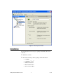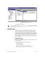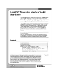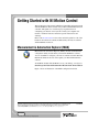
1
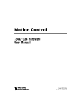
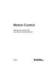
Getting Started with NI Motion Control
This document provides general guidelines for installing and getting started
with the NI-Motion driver software and your National Instruments motion
controller. This guide also contains step-by-step instructions for
configuring your motion control system. Consult your computer user
manual or technical reference manual for specific instructions and
warnings.
Refer to the Documentation section at the end of this guide for a list of the
hardware and software documents included with your motion controller
and the NI-Motion software.
Measurement & Automation Explorer (MAX)
Measurement & Automation Explorer (MAX), the National Instruments
configuration utility, installs when you install the NI-Motion software.
You can use MAX to configure your motion controller and other National
Instruments hardware devices and to update your National Instruments
software.
To run MAX, double-click the MAX icon on your desktop, or navigate to
Start»Programs»National Instruments»Measurement & Automation.
Figure 1 shows an illustration of the MAX configuration window.
CVI™, LabVIEW™, National Instruments™, NI™, ni.com™, NI-Motion™, NI Motion Assistant™, and RTSI™ are
trademarks of National Instruments Corporation. Product and company names mentioned herein are trademarks or trade
names of their respective companies. For patents covering National Instruments products, refer to the appropriate
location: Help»Patents in your software, the patents.txt file on your CD, or ni.com/patents.
ni.com
© 2003 National Instruments Corp. All rights reserved.
April 2003
323329A-01
Figure 1. MAX Configuration Window
Installation
The following items are necessary for getting started with your motion
controller:
❑ NI-Motion software
❑ One of the following software packages and documentation:
Getting Started with NI Motion Control
–
LabVIEW
–
LabWindows™/CVI™
–
NI Motion Assistant
–
Microsoft Visual C++
–
Microsoft Visual Basic
2
ni.com
❑ An NI motion controller
❑ A computer with an available PXI or PCI slot or IEEE 1394
NI-Motion Software Installation
Install the NI-Motion software before installing a motion controller for the
first time. If you are upgrading from a previous version of the NI-Motion
software, it is not necessary to remove your controller before installing the
upgrade. The upgrade does not affect your existing Windows
configuration.
Complete the following steps to install your NI-Motion software.
1.
Insert the NI-Motion CD into your CD-ROM drive to display the
NI-Motion installation screen.
2.
Click Install NI-Motion.
3.
Follow the installer prompts through the rest of the installation.
4.
Refer to the NI-Motion ReadMe.htm file after the installation is
complete for last-minute information not contained in this document or
the NI-Motion online help.
Your NI-Motion software is installed. You can install the included
NI Motion Assistant demo after your NI-Motion installation is complete.
Motion Controller Installation
The following section explains how to install your PCI, PXI, and FW
controllers.
When adding or removing a controller from a Windows 2000/NT/XP system, you
must be logged on with administrator-level access. After you have restarted your system,
you may need to refresh MAX to view your new controller.
Note
PCI Controllers
1.
Power off and unplug your computer.
Caution To protect yourself and the computer from electrical hazards, the computer
should remain unplugged until the installation is complete.
2.
Remove the cover to expose access to the PCI expansion slots.
3.
Choose an unused 5 V PCI slot, and remove the corresponding
expansion slot cover on the back panel of the computer.
© National Instruments Corporation
3
Getting Started with NI Motion Control
4.
Touch a metal part on your computer case to discharge any static
electricity that might be on your clothes or body before handling your
controller. Static electricity can damage your controller.
5.
Gently rock the controller into the slot. The connection may be tight,
but do not force the controller into place.
6.
If required, screw the mounting bracket of the controller to the back
panel rail of the computer.
7.
Replace the cover.
8.
Plug in and power on your computer.
Your PCI controller is installed.
PXI Controllers
1.
Power off and unplug your chassis.
Caution To protect yourself and the computer from electrical hazards, the computer
should remain unplugged until the installation is complete.
2.
Choose an unused +3.3 V or +5 V peripheral slot and remove the filler
panel.
3.
Touch a metal part on your chassis to discharge any static electricity
that might be on your clothes or body. Static electricity can damage
your controller.
4.
Insert your PXI controller into the chosen slot. Use the injector/ejector
handle to fully inject the device into place.
5.
Screw the front panel of the PXI controller to the front panel mounting
rails of the chassis.
6.
Visually verify the installation.
7.
Plug in and power on the chassis.
Your PXI controller is installed.
IEEE 1394
Note If you are not using the BP-1 battery pack, follow the instructions in this section.
If you are using the BP-1 battery pack, follow the installation instructions in your BP-1
Battery Pack Installation Guide and then begin with step 2.
1.
Connect the power cord to the wall outlet and the IEEE 1394
controller.
2.
Connect the IEEE 1394 cable from the computer or any other
IEEE 1394 device to the port on your FW controller. Your computer
Getting Started with NI Motion Control
4
ni.com
should immediately detect the controller. The COM LED on the front
panel blinks when the computer recognizes the controller.
3.
Verify that the power LED is on.
Your FW controller is installed.
Use the Power LED and the Communication LED (described below) to
determine the state of the device.
•
•
Power LED
–
Power LED off—The controller is receiving no power. Either the
power cord is unplugged or the power source is broken.
–
Power LED dim—The controller is receiving power but is not
connected to an active IEEE 1394 port.
–
Power LED on—The controller is receiving power and is
connected to an active IEEE 1394 port.
Communication LED—The COM LED blinks when the controller
sends or receives any commands or data. This LED should blink once
when you first plug in your controller. This light remains on or blinks
continuously when large amounts of data are transferring.
Firmware Updates
Firmware is software that is loaded onto your NI motion controller.
Firmware allows you to update your motion controller with new features
and updates. The latest firmware is automatically installed onto your
computer when you install the latest version of NI-Motion but must then
be downloaded to your NI motion controller.
Complete the following steps to update your firmware.
1.
Click the MAX icon on your desktop or select Start»Programs»
National Instruments»Measurement & Automation to open MAX.
2.
Expand Devices and Interfaces in the configuration tree. An
exclamation point on the motion controller icon indicates that the
motion controller firmware is outdated and must be updated.
3.
Click once on the NI motion controller you wish to update.
4.
Click the Firmware tab at the bottom of the window. An exclamation
point appears on each firmware sector requiring an update.
5.
Right-click the folder icon at the top of the firmware tree and select
Update All Firmware Sectors, as shown in Figure 2.
© National Instruments Corporation
5
Getting Started with NI Motion Control
Figure 2. Updating Your Firmware
Your firmware is now updated.
To find NI-Motion updates, visit ni.com/motion and select Drivers & Downloads.
For support questions, visit ni.com/support/motion.
Tip
LabVIEW RT Setup
Using NI motion control with LabVIEW RT is designed to be almost
identical to using NI motion control normally through a PCI motion
controller in the host machine. The only difference is that you must map
your remote PXI system to your local machine before you configure and
initialize your motion system. Then, you can program your motion control
application normally and retarget your application to the remote system.
Refer to MAX for more information about mapping your remote system to
your local machine.
LabVIEW RT Benefits
Benefits of using LabVIEW RT with a remote system for NI motion control
include the following:
•
Greater determinism than a Windows platform
•
Higher axis counts
•
Automatic RTSI support
•
Easier to program than onboard programming
•
More robust than a Windows PC-based motion system
Getting Started with NI Motion Control
6
ni.com
Configuring Steppers and Servos
This section explains how to configure and test your motion control system.
Before configuring your motor, install your motion hardware, including
motion controller, motors, amplifiers, encoders, UMI (if necessary), limits,
and home switches. Refer to the appropriate hardware documentation for
installation instructions. For more information on configuring and tuning
your motion control system, visit ni.com/support/motion.
Note
You must have a complete hardware setup to configure and test your servo system.
NI recommends having the NI motion controller axis inhibit outputs connected to
the drive. Inhibit outputs are typically used to disable the servo or stepper drive for power
savings, safety, or specific application reasons. For more information about inhibit outputs,
refer to the NI-Motion User Manual.
Note
To configure a stepper motor or test your system without a motor, refer to
the following information in the left column. For servo motors, refer to the
information in the right column.
Depending on the servo system, tuning may be required before making a
move. For more information about tuning a servo system, refer to the
NI-Motion User Manual.
© National Instruments Corporation
7
Getting Started with NI Motion Control
Stepper or No Motor
Servo Motor
Caution A servo motor may “run
Step 1
away” if not properly configured. This
response can be caused by the encoder
or motor being wired incorrectly or
poorly tuned. To help protect your
system from damage, NI recommends
setting the following error (position
error) in MAX to a value that will not
allow damage to the system. Refer to
the NI-Motion User Manual and the
MAX for Motion Online Help for more
information on setting following error.
Power on your hardware and open MAX.
In MAX, verify that your firmware is updated.
Refer to the Firmware Updates section in this
guide for information about updating your
firmware.
Step 2
Select a configuration in MAX.
1.
Double-click Devices and Interfaces.
2.
Double-click the name of your motion
controller.
3.
Click Default <controller> Settings
to display the configuration options.
4.
Select the Open Loop Stepper option
button.
5.
Click Apply on the MAX toolbar to save
your changes.
Step 1
Power on your hardware and open MAX.
In MAX, verify the firmware is updated. Refer
to the Firmware Updates section in this guide
for information about updating the firmware.
Step 2
Select a configuration in MAX.
Step 3
1.
Double-click Devices and Interfaces.
Click Initialize on the MAX toolbar to
initialize your motion controller.
2.
Double-click the name of your motion
controller.
Initializing your controller resets it to a known
starting state so that it is ready for commands.
3.
Click Default <controller> Settings
to display the configuration options.
4.
Select the Servo option button.
Step 4
Try to turn your motors by hand to check for
holding torque. Motors that hold firmly in place
exhibit holding torque, indicating that they are
powered and responding to commands from the
motion controller.
Getting Started with NI Motion Control
Note This assumes you are using
brushed servo motors. Refer to the
7350 Hardware User Manual for
more information about configuring
brushless servo motor hardware.
8
5.
Set the value for encoder counts/revolution
in MAX. Refer to your motor or encoder
documentation for the correct values.
6.
Click Apply on the MAX toolbar to save
your changes.
ni.com
Stepper or No Motor
Servo Motor
Step 5
Step 3
Perform a single-axis test in MAX.
1.
Click Initialize on the MAX toolbar to
initialize your motion controller.
Double-click the Interactive folder in the
configuration tree.
2.
Select 1-D Interactive.
3.
Enter 10000 in the Target Position field.
4.
Click the Apply button just below the
Target Position field.
5.
Click Start on the toolbar. As the motor
rotates, the Position field under Current
Trajectory Data increases to 10,000.
The Position field should still change to
10,000, regardless of whether or not a
motor is attached.
6.
Click the Kill button on the toolbar to allow
your motor to rotate freely.
7.
Turn your motor by hand. Notice that the
Position field under Current Trajectory
Data does not change. Stepper motors
operating in open-loop mode cannot read
a change in the position of the motor.
Initializing your controller resets it to a known
starting state so that it is ready for commands.
Step 4
Try to turn your motors by hand to check for
holding torque. Motors that are “springy” and
return to their original position exhibit holding
torque, indicating that they are powered and
responding to commands from the motion
controller.
Step 5
Perform a single-axis test in MAX.
Note Depending on the servo system,
tuning may be required before making
a move. For more information about
tuning a servo system, refer to the
NI-Motion User Manual and MAX for
Motion Online Help.
You have successfully configured and tested
your motion controller.
If you have encoders on your stepper motor,
continue with steps 6 and 7.
Step 6
Apply a change in MAX.
1.
Select Default <controller> Settings in
the configuration tree.
2.
Select the Closed Loop Stepper option
button.
© National Instruments Corporation
9
1.
Double-click the Interactive folder in the
configuration tree.
2.
Select 1-D Interactive.
3.
Enter 10000 in the Target Position field.
4.
Click the Apply button just below the
Target Position field.
5.
Click Start on the toolbar. As the motor
rotates, the Position field under Current
Trajectory Data increases to 10,000.
6.
Click the Kill button on the toolbar to allow
your motor to rotate freely.
7.
Turn your motor by hand. Notice that the
Position field under Current Trajectory
Data changes as you move your motor.
Getting Started with NI Motion Control
Stepper or No Motor
3.
Set the values for Encoder counts per
revolution and Stepper steps per
revolutions in MAX. Refer to your motor
or encoder documentation for the correct
values.
4.
Click Apply on the toolbar.
5.
Click Initialize on the MAX toolbar to
initialize your motion controller.
Servo Motor
You have successfully configured and tested
your motion controller.
Step 7
Perform a closed-loop stepper test.
1.
Click 1-D Interactive in the configuration
tree.
2.
Click Apply at the bottom of the window.
3.
Click Kill on the toolbar.
4.
Rotate your motor by hand. The Position
field under Current Trajectory Data
should change as you turn your motor.
You have successfully configured and tested
your motion controller and encoders.
Getting Started with NI Motion Control
10
ni.com
Documentation
This section summarizes each piece of documentation included with your
NI motion controller and the NI-Motion software. Use this information to
determine which piece of documentation will be useful for your task.
•
Motion controller hardware user manual—The hardware user
manual describes the electrical and mechanical aspects of your motion
controller and contains information about its installation and
operation.
•
NI-Motion User Manual—The software user manual is task-based
and takes you through each phase of designing and executing a motion
application. This document contains information about selecting a
motor, how to design a basic move, how to design a multi-axis move,
incorporating vision and DAQ into motion applications, and how to
work with common motion concepts, such as BODE analysis,
contouring, and breakpoints.
•
NI-Motion ReadMe—This document contains any changes made to
the software, the usual “What’s New” information, as well as system
requirements and any known issues.
•
NI-Motion C Reference Help—This help file for C and Visual Basic
environment applications includes dedicated function reference files,
and provide details about each function, including description,
parameters, illustrations (diagram or code), and error codes.
•
NI-Motion VI Help—This help file for LabVIEW applications
includes dedicated VI reference files, and provide details about each
VI, including description, control and input terminals, usage,
illustrations (diagram or code), and error codes.
•
MAX for Motion Online Help—This help file provides information
about using MAX to configure your motion controller.
© National Instruments Corporation
11
Getting Started with NI Motion Control