1
LabVIEW™ Simulation Interface Toolkit
User Guide
The LabVIEW Simulation Interface Toolkit integrates LabVIEW with the
software of The MathWorks, Inc. known as Simulink and Real-Time
Workshop in a way that allows you to develop, prototype, and test control
systems using models developed in the Simulink simulation environment.
This user guide contains the system requirements, installation instructions,
and upgrade information for the Simulation Interface Toolkit. This user
guide also provides a conceptual overview of the Simulation Interface
Toolkit and the benefits in using LabVIEW with Simulink models.
Exercises in this user guide teach you how to create LabVIEW user
interfaces for Simulink models and run simulations on NI RT Series
hardware.
For more information…
Refer to the LabVIEW Bookshelf for information about LabVIEW and to access
the LabVIEW help resources. Access the LabVIEW Bookshelf by selecting Start»
Programs»National Instruments»LabVIEW»Search the LabVIEW Bookshelf.
Contents
System Requirements.............................................................................. 2
Installation Instructions........................................................................... 3
Upgrading from Version 1.0 ................................................................... 3
Introduction to the Simulation Interface Toolkit .................................... 4
LabVIEW, Simulink, and Real-Time Workshop............................. 4
Creating a LabVIEW User Interface for a Simulink Model ............ 4
Converting a Simulink Model into a DLL....................................... 6
Communicating with the Model DLL ............................................. 7
LabVIEW™, National Instruments™, NI™, ni.com™, and NI-DAQ™ are trademarks of National Instruments Corporation.
Simulink®, Real-Time Workshop®, and MATLAB® are registered trademarks of The MathWorks, Inc. Further, product and
company names mentioned herein are trademarks, registered trademarks, or trade names of their respective companies.
For patents covering National Instruments products, refer to the appropriate location: Help»Patents in the software, the
patents.txt file on your CD, or ni.com/patents. You are only permitted to use this product in accordance with
the accompanying license agreement. All rights not expressly granted to you in the license agreement accompanying the
product are reserved to NI. Further, and without limiting the forgoing, no license or any right of any kind (whether by
express license, implied license, the doctrine of exhaustion or otherwise) is granted under any NI patents or other
intellectual property right of NI with respect to any other product(s) of NI or of anyone else (including without limitation,
the Simulink and the Real-Time Workshop products of The MathWorks, Inc.), including without limitation, the right to
use any of these other products.
ni.com
© 2002–2003 National Instruments Corp. All rights reserved.
October 2003
370420B-01
Tutorial: Creating a User Interface for a Simulink Model ......................9
Building a New Simulink Model......................................................9
SIT Server .................................................................................10
Setting the Simulation Parameters....................................................10
Creating the User Interface...............................................................11
LabVIEW and Simulink Data Types ........................................11
Specifying the Model .......................................................................12
Creating Connections .......................................................................14
Modifying Connections.............................................................16
Interacting with the Simulink Model................................................16
Understanding the Block Diagram of the Host VI ..................................18
Initializing the Simulation ................................................................18
Changing Parameter Values Using LabVIEW Controls ..................19
Updating the Indicator Values..........................................................21
Tutorial: Converting a Simulink Model into a Model DLL ....................21
Tutorial: Communicating with the Model DLL ......................................23
Understanding Model VIs, Driver VIs, and a Model DLL......................25
Model Interface VIs..........................................................................26
Exchanging Data with the Model DLL ............................................26
Creating a LabVIEW VI to Call the Model DLL.............................27
Creating a Real-Time Model-Based Controller ...............................28
Running Simulations without the Simulation Interface
Toolkit Server ................................................................................29
Simple Model Interface VIs .............................................................30
Modifying Parameters in the Model DLL Using a Driver VI ..........30
Designing a Batch Simulation .................................................................32
Setting the Initial Conditions for the Batch Simulation ...................32
Understanding the Block Diagram of the Batch Simulation VI.......34
Initializing the Batch Simulation...............................................34
Setting the Parameter Values ....................................................34
Updating the Output Indicator...................................................35
Where to Go from Here ...........................................................................36
System Requirements
To use the Simulation Interface Toolkit, you must be a properly licensed
user of and have the following software installed on the host computer.
•
The MathWorks MATLAB 6.0 or later
•
The MathWorks Simulink 4.0 or later
•
The MathWorks Real-Time Workshop 4.0 or later
•
Microsoft Visual C++ 5.0 or later
•
National Instruments LabVIEW 7.0 or later, Full or Professional
Development Systems
LabVIEW Simulation Interface Toolkit User Guide
2
ni.com
To use the Simulation Interface Toolkit with RT Series hardware, you must
have the following software and hardware.
•
National Instruments LabVIEW Real-Time Module
•
National Instruments RT Series hardware
To use the Simulation Interface Toolkit for data acquisition (DAQ)
applications, you must have the following software and hardware.
•
NI-DAQ
•
National Instruments data acquisition hardware
Installation Instructions
Complete the following steps to install the Simulation Interface Toolkit.
1.
Insert the LabVIEW Simulation Interface Toolkit CD.
2.
Run the setup.exe program.
3.
Follow the instructions that appear on the screen.
If you want to run simulations on RT targets, you need to configure the
RT Series devices using Measurement & Automation Explorer (MAX).
Complete the following steps to install the Simulation Interface Toolkit
on a networked RT Series device.
1.
In MAX, select the device from the Remote Systems category.
2.
Click the Software tab to see a list of software available on the host
computer and the software currently on the device.
3.
If NI-Simulation Interface Toolkit 2.0 is not present on
the remote device, click the Install Software button to open the Select
software to download dialog box.
4.
Follow the instructions that appear on the screen to install the software.
Refer to the Measurement & Automation Explorer Remote Systems Help,
available by selecting Help»Help Topics»Remote Systems from MAX,
for information about using MAX to configure remote systems.
Upgrading from Version 1.0
You cannot have both version 1.0 and 2.0 of the Simulation Interface
Toolkit installed on the same computer. You must uninstall version 1.0 of
the Simulation Interface Toolkit before you can install version 2.0 of the
Simulation Interface Toolkit.
You must modify any application you created using version 1.0 of the
Simulation Interface Toolkit because the Simulation Interface VIs changed.
© National Instruments Corporation
3
LabVIEW Simulation Interface Toolkit User Guide
The VIs located on the Simulation Interface palette in version 1.0 now are
located on the Model Interface palette. Open all applications created with
version 1.0 and replace the Simulation Interface VIs with the Model
Interface VIs.
You also must recompile all model DLLs built in version 1.0 using
version 2.0 of the Simulation Interface Toolkit.
Introduction to the Simulation Interface Toolkit
The Simulation Interface Toolkit provides methods for creating a
LabVIEW user interface for a Simulink model, converting a Simulink
model into a dynamic link library (DLL), and running a simulation model
on an RT target. By combining the capabilities of Simulink and Real-Time
Workshop with LabVIEW, the Simulation Interface Toolkit helps you
import simulation models into LabVIEW.
LabVIEW, Simulink, and Real-Time Workshop
LabVIEW is a graphical programming language that uses icons instead of
lines of text to create applications. LabVIEW applications often are called
virtual instruments, or VIs, because their appearance and operation often
imitate physical instruments, such as oscilloscopes and multimeters.
Simulink, an add-on toolkit for MATLAB, provides a graphical
environment for the design and interactive execution of dynamic system
models. You can create models in Simulink using customizable blocks.
Using graphical wires to connect the blocks, you can specify data flow.
Real-Time Workshop is an add-on package for Simulink that generates
C code from Simulink models. Real-Time Workshop then uses a
C compiler to compile the C code for execution on various real-time
targets.
Creating a LabVIEW User Interface for a Simulink Model
The Simulation Interface Toolkit provides a way to create a LabVIEW
user interface that you can use to interact with a Simulink model. With a
LabVIEW user interface, you can manipulate the model parameters and
view the output data of the Simulink model.
Note The Simulation Interface Toolkit does not allow you to use a LabVIEW user
interface in conjunction with a Simulink user interface.
To use the Simulation Interface Toolkit, you must have LabVIEW and
MATLAB running on the host computer. The host computer is the
LabVIEW Simulation Interface Toolkit User Guide
4
ni.com
computer where you create the LabVIEW user interface. The host
computer must be a PC with a Windows operating system (OS) other
than the host computer. LabVIEW exchanges data with MATLAB and
Simulink using TCP/IP.
Note You can have MATLAB and Simulink running on another PC with a Windows OS.
If you have LabVIEW and MATLAB running on different computers, you must install the
Simulation Interface Toolkit on both computers.
For LabVIEW to communicate successfully with MATLAB and Simulink,
you must have MATLAB running. When you launch MATLAB, you also
start the Simulation Interface Toolkit (SIT) Server, which enables
LabVIEW and MATLAB to communicate with each other.
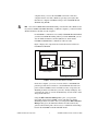
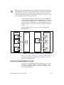
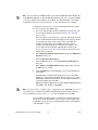
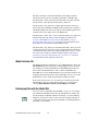
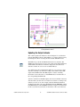
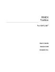
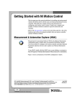
Figure 1 displays the components involved in the interaction between
LabVIEW and Simulink.
LabVIEW
Host VI
MATLAB and Simulink
Front Panel
Block
Diagram
SIT Server
model
TCP/IP
Host Computer
Host Computer or Another PC
Figure 1. Running a Simulink Model in LabVIEW
On the host computer, you create a host VI, which is a LabVIEW front
panel that provides the user interface to the Simulink model. This front
panel contains LabVIEW controls and indicators that correspond to the
Simulink parameters and sinks that you want to modify and display. You
can change the values of controls and immediately view the results of that
change in the indicators.
Using the SIT Connection Manager dialog box, you specify the
relationship between the LabVIEW controls and indicators and the
Simulink parameters and sinks. After you configure the SIT Connection
Manager dialog box, the Simulation Interface Toolkit automatically
generates the block diagram code necessary to establish the relationships
between the LabVIEW VI and the Simulink model.
© National Instruments Corporation
5
LabVIEW Simulation Interface Toolkit User Guide
Note For advanced LabVIEW programmers, the Simulation Interface Toolkit installs
a User Interface palette that contains VIs with which you can build customized block
diagrams. You can use these User Interface VIs to replicate the block diagram code
generated by the Simulation Interface Toolkit. Refer to the Simulation Interface Toolkit
Help for information about the User Interface VIs.
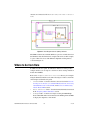
Using the Simulation Interface Toolkit, you can connect multiple VIs
created on the host computer to the same Simulink model. You also can
connect multiple Simulink models on the same computer to a single VI
created on the host computer. However, if the Simulink models are on
different computers, you cannot connect the same VI to these different
models.
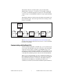
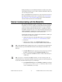
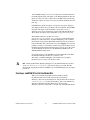
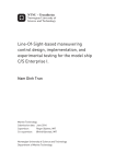
Figure 2 illustrates the two ways you can connect LabVIEW VIs to
Simulink models.
MATLAB and
Simulink
LabVIEW
MATLAB and
Simulink
LabVIEW
Host VI 1
model
1
Host VI
Host VI 2
TCP/IP
TCP/IP
model
2
model
Host VI n
model
n
Figure 2. Connecting Multiple LabVIEW VIs and Multiple Simulink Models
The Tutorial: Creating a User Interface for a Simulink Model section
provides step-by-step procedures that teach you how to create a user
interface for a Simulink model.
Converting a Simulink Model into a DLL
If you want to run a Simulink model on an RT target, you can convert
the model into a dynamic link library (DLL) that LabVIEW can call.
To convert a Simulink model file, or.mdl file, into a DLL, you must
use Real-Time Workshop.
LabVIEW Simulation Interface Toolkit User Guide
6
ni.com
The Simulation Interface Toolkit includes a plug-in for Real-Time
Workshop that converts the .mdl file into C code and then compiles the
C code into a model DLL using Microsoft Visual C++. The model DLL
contains all aspects of the Simulink model but no longer requires Simulink
to run.
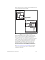
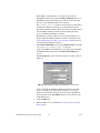
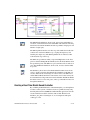
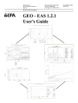
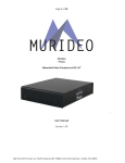
The Simulation Interface Toolkit automatically builds a model VI that calls
the model DLL. Figure 3 shows the steps involved in converting a model
file into a model DLL.
Simulation
Interface
Toolkit
model
Real-Time
Workshop
C code
Microsoft
Visual C++
Model
DLL
Simulation
Interface
Toolkit
Model
VI
Figure 3. Converting a Simulink Model into a Model DLL
The Tutorial: Converting a Simulink Model into a Model DLL section
provides step-by-step procedures that teach you how to convert a Simulink
model into a model DLL.
Communicating with the Model DLL
To interact with the model DLL on the RT target, you can use the host VI
you created for the Simulink model as the user interface. The model DLL
contains the same parameters and sinks as the Simulink model, so the
connections you made between the LabVIEW controls and indicators and
the Simulink parameters and sinks remain the same. Using the host VI, you
can modify the model DLL parameters and view the results immediately.
When you create the model DLL, you create a simulation model that can
run on an RT target. When you run the host VI, you can choose to download
the model DLL and model VI to an RT target. The Simulation Interface
Toolkit then starts the SIT Server on the RT target. The host VI
communicates with the model VI and model DLL through the SIT Server.
© National Instruments Corporation
7
LabVIEW Simulation Interface Toolkit User Guide
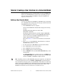
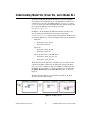
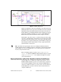
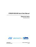
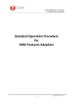
Figure 4 illustrates how the host computer interacts with the RT target after
you download the model VI and model DLL.
LabVIEW
Host VI
Front Panel
Block
Diagram
TCP/IP Network
Host Computer
LabVIEW Real-Time Module
Model VI
Block
Diagram
SIT Server
Model
DLL
RT Target
Figure 4. Running a Simulation on an RT Target
The Real-Time Module extends the capabilities of the existing TCP
functions to enable communication with networked RT Series devices.
However, TCP functions are non-deterministic, and using TCP
communication in a time-critical VI reduces determinism. The Simulation
Interface Toolkit configures the TCP/IP communication between the
host VI and model VI. This TCP/IP communication, coupled with
Real-Time FIFOs, is deterministic and does not affect the overall
determinism of the time-critical VI. Refer to Chapter 4, Building
Deterministic Applications, of the LabVIEW Real-Time Module User
Manual for information about TCP communication and RT FIFOs.
The Tutorial: Communicating with the Model DLL section provides
step-by-step procedures that teach you how to communicate with a
model DLL on an RT target.
LabVIEW Simulation Interface Toolkit User Guide
8
ni.com
Tutorial: Creating a User Interface for a Simulink Model
In the following exercises, you will learn how to create a LabVIEW user
interface for a Simulink model. You will create a model that generates a
sine wave, then you will use LabVIEW to change the amplitude and
frequency of the sine wave.
Building a New Simulink Model
To create a user interface in LabVIEW for a Simulink model, you first must
have a Simulink model. Complete the following steps to build a new model
in Simulink that generates a sine wave.
1.
Launch MATLAB on the host computer.
Notice how the MATLAB command window displays the following
message:
Starting the SIT Server on Port 6011
SIT Server started
Installing the Simulation Interface Toolkit configures MATLAB to
launch the SIT Server when you launch MATLAB. The SIT Server
transfers data between LabVIEW and MATLAB. This message
indicates that the SIT Server is running.
Refer to the SIT Server section for more information about the SIT
Server.
2.
Enter simulink in the MATLAB command window to launch the
Simulink Library Browser window.
3.
In a new model, place a Sine Wave block in the model window.
4.
Place an In1 input port in the model window.
5.
Place a Sum function in the model window.
6.
Place an Out1 output port in the model window.
7.
Place an NISink block, located in the NI Toolkit Sinks library, in the
model window.
The NI Toolkit Sinks library contains two blocks—the NISink block
and the NIXYGraph block. These two blocks export the output of the
model to LabVIEW so LabVIEW can display the data.
Note Depending on the rate at which Simulink generates the output data, you might want
to change the decimation factor for the NISink or NIXYGraph block. The decimation
factor specifies how many data points you want Simulink to return. This factor affects the
number of data points LabVIEW receives and displays in the waveform chart or XY graph.
If you want to display fewer data points, increase the decimation factor. Refer to The
MathWorks documentation for more information on decimation factors.
© National Instruments Corporation
9
LabVIEW Simulation Interface Toolkit User Guide
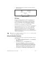
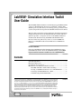
8.
Wire the sources, functions, and sinks so the model looks like the
diagram in Figure 5.
Figure 5. SineWave Model
SIT Server
By default, the Simulation Interface Toolkit starts the SIT Server on
port 6011 by executing the NiMatlabServer command. However,
you can modify the port on which the SIT Server starts by modifying
the startup.m file. The startup.m file contains the command
NiMatlabServer('start',6011). To change the port on which
the SIT Server starts, change 6011 to another port number.
If you want to temporarily change the port number, first stop the SIT Server.
Then enter the NiMatlabServer('start',XXXX) command in the
MATLAB command window, where XXXX is the port number. This
command starts the SIT Server on the new port specified. To stop the
SIT Server, enter the NiMatlabServer('stop') command in the
MATLAB command window. You do not need to specify the port number
when you stop the SIT Server.
Note The startup.m file is located in the MATLABxx\toolbox\local directory, where
xx is the version of MATLAB you are using.
Setting the Simulation Parameters
Complete the following steps to change the stop time and the solver type
for the simulation.
1.
Select Simulation»Simulation Parameters to open the Simulation
Parameters dialog box.
2.
On the Solver tab, type inf in the Stop time text box.
By changing the Stop time to an infinite value, the simulation
runs until you stop it. The default stop time for this simulation is
10.0 seconds. If you use the default stop time, the simulation might
end before you can adjust the values of the parameters. To interact
with this model, the simulation stop time might need to be longer.
3.
Set the Type option to Fixed-step in the Solver Options section.
LabVIEW Simulation Interface Toolkit User Guide
10
ni.com
4.
Save the model as SineWave.mdl.
Refer to The MathWorks documentation for information about setting
simulation parameters such as the simulation time and solver type.
Creating the User Interface
To interact with the SineWave model using a LabVIEW user interface, you
need to create the user interface in LabVIEW. You need controls for
manipulating parameters in the SineWave model and indicators to display
the generated sine wave. Complete the following steps to create the
controls and indicators that reflect the parameters and sinks of the
SineWave model.
1.
Launch LabVIEW on the host computer.
2.
In the LabVIEW dialog box, click the arrow on the New button and
select Blank VI from the shortcut menu.
Notice that a blank front panel and block diagram appear.
Refer to the Getting Started with LabVIEW manual for more
information about the LabVIEW graphical programming environment.
The Getting Started with LabVIEW manual helps you build VIs and
introduces you to basic programming techniques in LabVIEW.
3.
Select a knob control and place it on the front panel of the VI.
4.
Label the knob Amplitude.
5.
Create another knob labeled Frequency.
6.
Select the waveform chart and place it on the front panel of the VI.
This waveform chart displays information contained in the NISink
block. You can use any numeric indicator to display the data contained
in the NISink block; however, you must use an XY graph to display
information contained in the NIXYGraph block.
Refer to the LabVIEW User Manual for more information about when
to use the waveform chart and when to use the XY graph in LabVIEW.
7.
Label the waveform chart Sine Wave.
8.
Save the VI as Sine Wave.vi.
LabVIEW and Simulink Data Types
On a non-RT target, Simulink parameters are adaptable at edit time. If you
create a LabVIEW control data type that does not match the Simulink
parameter data type, you still can run the simulation model. When you run
the simulation model, the parameter data type adapts to the corresponding
control data type. Valid LabVIEW data types include scalars, 1D arrays,
2D arrays, and strings.
© National Instruments Corporation
11
LabVIEW Simulation Interface Toolkit User Guide
However, Simulink parameters are a fixed data type at run time. If you
modify a LabVIEW control whose data type does not match the parameter
data type, the parameter cannot receive parameter updates from LabVIEW.
Simulink generates an error and stops running.
For simulation models running on an RT target, the parameters are a fixed
data type. If the control data types do not match the parameter data types,
the simulation model cannot run. You must know the data type of the
connected parameters when configuring the controls.
Refer to Chapter 5, Building the Block Diagram, of the LabVIEW User
Manual for more information about LabVIEW data types. Refer to
The MathWorks documentation for more information about Simulink
parameter data types.
Specifying the Model
After creating the VI, you need to specify with which model you want the
VI to communicate. Using the SIT Connection Manager dialog box, you
can specify this model. Complete the following steps to select the
SineWave model.
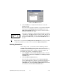
1.
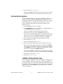
On the front panel menu bar, select Tools»SIT Connection Manager
to launch the SIT Connection Manager dialog box, shown in
Figure 6.
The SIT Connection Manager dialog box establishes connections
between LabVIEW controls and indicators and parameters and sinks
in a Simulink model.
Figure 6. SIT Connection Manager Dialog Box
LabVIEW Simulation Interface Toolkit User Guide
12
ni.com
Notice how the Controls and indicators listbox displays the
LabVIEW controls and indicators you created on the front panel of the
Sine Wave VI. Also notice how the Model parameters and sinks
listbox does not contain any items. You must load a simulation model
before the Simulink parameters and sinks appear in the listbox.
2.
Click the Load Model button to display the Select Host dialog box.
Note You must have MATLAB and the SIT Server running before you can load a
Simulink model.
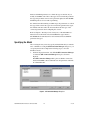
3.
In the Select Host dialog box, shown in Figure 7, make sure the
Machine Name/IP is localhost and the Port is 6011.
By selecting localhost, you indicate to LabVIEW that the computer
on which MATLAB and Simulink reside is the host computer. You
also can enter the IP address of another Windows PC if MATLAB,
Simulink, and the SIT Server are running on that computer.
Figure 7. Select Host Dialog Box
You can change the port number if port 6011 is not available. Refer to
the SIT Server section for information about specifying this port
number.
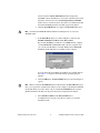
4.
Click the OK button. The Select Model dialog box, shown in Figure 8,
appears.
Note When you click the Load Model button for the first time, the Select Host dialog box
asks you to specify the computer name and port of the computer containing the Simulink
model with which you want to interact. If you click the Load Model button again, the
Simulation Interface Toolkit uses the previously entered computer name and port.
5.
Select SineWave.mdl from the Select model listbox.
You might need to navigate to the directory where you saved the
SineWave model.
© National Instruments Corporation
13
LabVIEW Simulation Interface Toolkit User Guide
Figure 8. Select Model Dialog Box
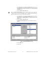
6.
Click the OK button or double-click the filename to select the
SineWave model.
Notice how all the parameters and sinks associated with the SineWave
model appear in the Model parameters and sinks listbox in the
SIT Connection Manager dialog box. You can connect controls to
parameters and indicators to sinks.
Icons next to a parameter or sink name indicate whether the variable is
a parameter or a sink. The parameter icon, shown at left, indicates that
you can connect LabVIEW controls to the parameter. The sink icon,
shown at left, indicates that you can connect LabVIEW indicators to
the sink.
To remove a model from the Model parameters and sinks listbox, select a parameter
or sink in the model that you want to remove and click the Remove Model button.
Tip
Creating Connections
After loading a model, you must indicate which Simulink parameters
and sinks correspond with which LabVIEW controls and indicators.
The SIT Connection Manager dialog box establishes these relationships.
Complete the following steps to create the connections needed to run
the simulation model using a LabVIEW user interface.
1.
Select Amplitude in the Controls and indicators listbox and select
Model SineWave»Sine Wave»Amplitude in the Model parameters
and sinks listbox.
2.
Click the Add to Connections button.
Notice how the connection appears in the Current connections
section, which lists all the connections you made. If you decide you
do not need a connection, select that connection in the Current
connections table and click the Delete Connection button. To remove
all connections, click the Clear Connections button.
LabVIEW Simulation Interface Toolkit User Guide
14
ni.com
3.
Select Frequency in the Controls and indicators listbox and select
Model SineWave»Sine Wave»Frequency in the Model parameters
and sinks listbox.
4.
Click the Add to Connections button.
Note The SIT Connection Manager dialog box indicates when you create an invalid
connection, such as connecting a LabVIEW control to a Simulink sink. The Simulation
Interface Toolkit prevents you from creating invalid connections.
5.
Select Sine Wave in the Controls and indicators listbox and select
Model SineWave»NISink»NISink in the Model parameters and
sinks listbox.
6.
Click the Add to Connections button.
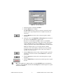
The SIT Connection Manager dialog box should look similar to
Figure 9.
Figure 9. SIT Connection Manager Dialog Box
7.
Click the OK button.
8.
Save this VI.
© National Instruments Corporation
15
LabVIEW Simulation Interface Toolkit User Guide
After you create connections between LabVIEW controls and indicators
and Simulink parameters and sinks, the Simulation Interface Toolkit
generates the block diagram code that governs the interaction between
LabVIEW and Simulink.
The Simulation Interface Toolkit generates this block diagram code from
a template VI. You do not need to edit this block diagram because the
template VI already contains the necessary VIs and functions to interact
with the Simulink model.
Refer to the Understanding the Block Diagram of the Host VI section for
more information about the automatically generated block diagram code.
Modifying Connections
After you load a Simulink model into the SIT Connection Manager dialog
box and configure the connections, the SIT Connection Manager dialog
box retains the model information. Each subsequent time you launch the
SIT Connection Manager dialog box, the Model parameters and sinks
listbox displays the parameters and sinks of that Simulink model.
If you want to modify the existing connections between the host VI and
the Simulink model, relaunch the SIT Connection Manager dialog box,
delete the connections you want to modify, and create new connections.
If you want to create new controls and indicators on the front panel, add the
controls and indicators and relaunch the SIT Connection Manager dialog
box. The SIT Connection Manager dialog box recognizes the new
controls and indicators and allows you to create more connections between
these controls and indicators and the Simulink parameters and sinks.
Interacting with the Simulink Model
After creating connections in the SIT Connection Manager dialog box,
you can run the VI. When you run the VI, the VI communicates with the
model on the host computer and runs the simulation. Complete the
following steps to run the VI.
1.
Display the front panel of the VI.
2.
Click the Run button, shown at left, to run the VI. The Select Host
dialog box, shown in Figure 10, appears.
LabVIEW Simulation Interface Toolkit User Guide
16
ni.com
Figure 10. Select Host Dialog Box
3.
Verify that the host computer is localhost.
4.
Click the OK button to continue.
The Select Host dialog box appears each time you run the VI. You
have the option of specifying a new host computer every time you
run the VI.
5.
Click the Run button, shown at left, on the front panel to run the
simulation.
6.
Adjust the values of the Amplitude and Frequency knobs and observe
the changes on the Sine Wave waveform chart.
Because you connected the LabVIEW controls to the Simulink
parameters, when you adjust the values of the controls, the parameter
values in Simulink change. Using LabVIEW, you can interactively
change the parameters of the model and immediately view the results.
While the simulation runs you can change run-time, editable
parameters, such as the frequency of the sine wave. If you attempt
to change the value of a parameter whose value cannot change at
run time, you receive an error.
7.
Click the Pause button, shown at left, on the front panel to pause the
simulation. To resume execution, click the Run button on the front
panel again.
8.
Click the Stop button, shown at left, on the front panel to stop the
simulation.
9.
Click the STOP VI button, shown at left, on the front panel to stop the
host VI.
Note If the simulation is running when you click the STOP VI button, the simulation
continues to run in Simulink. You must click the Stop button on the front panel to stop the
simulation in Simulink.
© National Instruments Corporation
17
LabVIEW Simulation Interface Toolkit User Guide
Understanding the Block Diagram of the Host VI
The host VI you created provides the user interface to the Simulink model.
The Simulation Interface Toolkit automatically generates the block
diagram code for this VI when you use the SIT Connection Manager
dialog box. The block diagram always has the same structure regardless of
the number of connections established in the SIT Connection Manager
dialog box.
The block diagram initializes the simulation and defines the relationship
between the LabVIEW controls and indicators and the Simulink
parameters and sinks. When you change the values of the controls on the
front panel, the block diagram sends the new values to the Simulink model.
The block diagram then receives updates from the Simulink model and
displays the values in the corresponding LabVIEW indicators.
The block diagram code consists of three main sections—the code to
initialize the simulation, the code to set parameter values, and the code
to receive indicator updates from the simulation model.
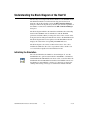
Initializing the Simulation
The code that initializes the simulation, shown in Figure 11, uses the
SIT Initialize VI to perform tasks needed for LabVIEW to communicate
with Simulink. The SIT Initialize VI, shown at left, creates the link to the
Simulink model. The SIT Initialize VI initiates the TCP/IP connection to
the SIT Server and establishes a database of connections to manage the
sending and receiving of messages to and from the simulation model.
LabVIEW Simulation Interface Toolkit User Guide
18
ni.com
Figure 11. Block Diagram Code for Initializing the Simulation
Notice the cluster of control references wired to the SIT Initialize VI. This
cluster allows the initialization code to read the values of the LabVIEW
controls. The SIT Initialize VI also creates several queues that LabVIEW
uses to communicate between sections of the VI that run in parallel.
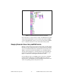
Changing Parameter Values Using LabVIEW Controls
Both the code that changes the parameter values and the code that updates
the indicator values reside in the outer Case structure that runs when there
are no errors with the initialization code. Inside this Case structure are two
While Loops that run in parallel. The While Loop containing the Event
structure, shown in Figure 12, is the block diagram code that handles the
user interaction with the front panel of the host VI. The While Loop in
Figure 13 contains the code that updates the indicator values.
If you modify the value of a LabVIEW control connected to a Simulink
parameter, the block diagram code within this While Loop sends the
changed value to the Simulink model. The Simulink model sets the value
of the corresponding parameter using this new value.
© National Instruments Corporation
19
LabVIEW Simulation Interface Toolkit User Guide
Figure 12. Block Diagram Code for Setting Parameter Values
The Event structure contains several event cases to handle various events.
In particular, the Value Change event is a dynamic event created in the
SIT Initialize Event VI, shown at left, to monitor changes in the values of
the controls on the front panel. This event executes when a control value
associated with a model parameter changes.
For example, when you change the value of the Frequency knob, which is
associated with the model parameter Frequency, the Value Change event
executes. The VI sends the new value of the Frequency knob to the
simulation model and specifies that the new value applies to the Frequency
parameter.
Also notice the SIT Loop Control VI, shown at left, located outside
the Event structure. This VI controls when the two While Loops, in
Figures 12 and 13, terminate. The two While Loops run in parallel until
you click the STOP VI button or the Stop button. When the SIT Loop
Control VI receives a stop command, it terminates the execution of both
While Loops.
Note When the VI stops executing, the VI saves the final values of the controls. The next
time you run the VI, the VI uses these values as the initial values of the controls.
The SIT Loop Control VI also gathers warnings, errors, and fatal errors
returned by Simulink. Warnings do not interrupt the simulation. When
Simulink encounters an error, the Simulation Interface Toolkit displays
a dialog box that gives you the option of stopping the host VI. However,
when Simulink encounters a fatal error, the Simulink application always
terminates, which terminates the host VI.
LabVIEW Simulation Interface Toolkit User Guide
20
ni.com
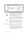
Updating the Indicator Values
The second While Loop, shown in Figure 13, displays the block diagram
code that reads values output by the simulation model and updates the
values on LabVIEW front panel indicators. This While Loop contains
a Case structure, which contains a case for each LabVIEW indicator
connected to a Simulink sink.
When the VI receives an update from the SIT Server, the VI places a
message into a queue for the While Loop to read. The elements in the queue
contain all the information necessary to display the sink value in the
corresponding LabVIEW indicator.
The While Loop also contains a timeout set to 100 ms. If the While Loop
does not receive an indicator update within 100 ms of the last indicator
update, the While Loop checks for a stop command.
Figure 13. Block Diagram Code for Updating Indicators
When you add, delete, or modify a connection in the SIT Connection
Manager dialog box, the Simulation Interface Toolkit regenerates this
section of the block diagram code.
Tutorial: Converting a Simulink Model into a Model DLL
The Simulation Interface Toolkit enables you to create DLLs from
Simulink models through Real-Time Workshop and Microsoft Visual C++.
Real-Time Workshop converts the .mdl file into C code and then
Microsoft Visual C++ compiles the C code into a DLL. The result is a DLL
based on a Simulink model that you can call in LabVIEW using the VIs on
the Simulation Interface palette.
© National Instruments Corporation
21
LabVIEW Simulation Interface Toolkit User Guide
Note If you are using a LabVIEW module, such as the LabVIEW Real-Time Module, the
LabVIEW FPGA Module, or the LabVIEW PDA Module, make sure you target LabVIEW
to the host computer before building a model DLL. Real-Time Workshop cannot build a
model DLL if you have an open connection to a target other than the host computer.
Complete the following steps to convert the Simulink model into a DLL
that you can download to an RT target.
1.
If you closed the SineWave model in Simulink, open the model again.
You created the SineWave model in the Building a New Simulink
Model section.
Notice the input port and output port you placed on the diagram when
you created the SineWave model. The input port and output port blocks
correspond to the inputs and the outputs of the model DLL. For
example, in DAQ applications, LabVIEW uses these blocks to
exchange data with a DAQ device. These blocks send data to and
receive data from the model DLL and DAQ device. Refer to the
Exchanging Data with the Model DLL section for information about
sending and receiving data.
2.
Select Simulation»Simulation Parameters to display the Simulation
Parameters dialog box.
3.
Click the Real-Time Workshop tab.
4.
Click the Browse button to open the System Target File Browser
dialog box.
5.
Select nidll.tlc—LabVIEW DLL Target from the listbox and click
the OK button to continue.
6.
Click the Build button in the Category section to begin building the
model DLL.
The MATLAB command window displays the status of Real-Time
Workshop as it builds the model DLL. The following message in the
MATLAB command window indicates that Real-Time Workshop has
completed building the model DLL.
### Successful completion of Real-Time Workshop build
procedure for model: ModelName.
Note If you do not have a compiler set up to compile the C code, MATLAB gives you an
error when trying to build the model DLL. The MATLAB command window displays a
message indicating you need to run mex -setup before building the model DLL.
After Real-Time Workshop builds a model DLL, the Simulation Interface
Toolkit places the model DLL into a project folder on the computer. The
model DLL contains all aspects of the Simulink model but is independent
of the Simulink .mdl file.
LabVIEW Simulation Interface Toolkit User Guide
22
ni.com
During the build process, the Simulation Interface Toolkit creates model
VIs and driver VIs that you use to interact with the model DLL. These VIs
also are in the project folder.
Refer to The MathWorks documentation for more information about how
Real-Time Workshop generates the C code. Refer to the Understanding
Model VIs, Driver VIs, and a Model DLL section for more information
about the model VIs, driver VIs, and model DLL.
Tutorial: Communicating with the Model DLL
By converting a Simulink model into a model DLL, you create a simulation
model that you can run on an RT target. Remember that this model DLL
contains all aspects of the Simulink model but is no longer a Simulink
model. You use the model VIs and driver VIs to communicate with the
model DLL. Using the host VI, you can download the model VI, driver VI,
and the model DLL to an RT target. You then can modify the parameters
of the model DLL by adjusting the controls in the host VI.
Complete the following steps to download the model DLL to an RT target
and communicate with the model DLL.
1.
Display the front panel of the Sine Wave VI that you created in the
Tutorial: Creating a User Interface for a Simulink Model section.
2.
Run the VI.
3.
While the VI is running, select Simulation»Retarget from the
run-time menu to select a new target on which to run the simulation.
Note If the Simulink model is running when you try to retarget the host VI, the Simulation
Interface Toolkit stops the Simulink model before downloading the model DLL to the
RT target.
4.
The Select Host dialog box appears. To select a new target, enter the
IP address of the RT target in the Machine Name/IP text box.
5.
Place a checkmark in the RT? checkbox to indicate that the target is
an RT target.
Note If you place a checkmark in the RT? checkbox, you must select the path to the
model VI. If you try to retarget the VI and do not specify a path, you cannot retarget the VI
because the VI assumes that the target is not an RT target.
6.
© National Instruments Corporation
In the Path to Model VI path, select SineWave_main.vi located in the
Matlabxx/work/SineWave_nidll_rtw directory, where xx is the
version of MATLAB you are using.
23
LabVIEW Simulation Interface Toolkit User Guide
If LabVIEW can determine the correct path to the model VI,
LabVIEW automatically specifies the Path to Model VI path for you.
LabVIEW searches in the model project folder located in the same
directory as the Simulink model for the model VI.
The SineWave_nidll_rtw folder is the model project folder where
the Simulation Interface Toolkit places all files generated by the
Real-Time Workshop build procedure. The folder also includes the VIs
that the Simulation Interface Toolkit generated during the build
process, including the SineWave_main VI.
The SineWave_main VI, which you call to run the simulation, is a
model VI that the Simulation Interface Toolkit created. Refer to the
Understanding Model VIs, Driver VIs, and a Model DLL section for
more information about the model VI.
7.
In the Path to Model DLL path, select the SineWave.dll located in the
Matlabxx/work/SineWave_nidll_rtw directory.
Again, if LabVIEW can determine the correct path to the model DLL,
LabVIEW automatically specifies the Path to Model DLL path
for you.
The Select Host dialog box should look similar to the dialog box in
Figure 14.
Figure 14. Downloading the Model VI and Model DLL to an RT Target
Again, by default, the Simulation Interface Toolkit starts the SIT
Server on port 6011. To change this port number, you can open
SineWave_main VI and change the constant wired to the SIT Start
Server VI. Then, in the Select Host dialog box, enter the new value
in the Port text box.
8.
Click the OK button.
9.
Run the simulation as you did in the Interacting with the Simulink
Model section.
LabVIEW Simulation Interface Toolkit User Guide
24
ni.com
Understanding Model VIs, Driver VIs, and a Model DLL
To create a model DLL, Real-Time Workshop converts the Simulink
model and any of its submodels into C code. Then Microsoft Visual C++
compiles the C code into a model DLL named ModelName.dll, where
ModelName is the name of the Simulink model. Real-Time Workshop then
places the model DLL into a new model project folder,
ModelName_nidll_rtw.
In addition to the model DLL, the Simulation Interface Toolkit creates
the following model VIs and driver VIs and places them in the
ModelName_nidll_rtw folder. The following model VIs and driver VIs
work with the SIT Server to call the model DLL and execute the simulation.
•
•
•
Model VIs
–
ModelName_main_daq VI
–
ModelName_main VI
Driver VIs
–
ModelName_driver_daq VI
–
ModelName_driver VI
Driver VIs that do not use the SIT Server
–
ModelName_driver_daq_base VI
–
ModelName_driver_base VI
The model VIs start the SIT Server on an RT target, call a driver VI that
calls the model DLL, and then stop the SIT Server when the simulation
stops. You cannot communicate with a model DLL on an RT target until
the SIT Server starts running, so you always must specify a model VI in
the Path to Model VI path in the Select Host dialog box, as shown in
Figure 11.
The block diagram in Figure 15 is the model VI, SineWave_main VI,
created for the Sine Wave example.
Figure 15. SineWave_main VI
© National Instruments Corporation
25
LabVIEW Simulation Interface Toolkit User Guide
The driver VIs interact with the model DLL and exchange parameter
information between the host VI and the model DLL on the RT target.
The ModelName_main_daq VI calls the ModelName_daq_driver VI and
the ModelName_main VI calls the ModelName_driver VI.
The ModelName_daq_driver VI is a DAQ application that reads analog
input values from a multifunction DAQ board, sends the values as inputs to
the SIT Step Model VI, retrieves the outputs from the SIT Step Model VI,
and writes the analog outputs to the same DAQ board.
The ModelName_driver VI is a version of the ModelName_daq_driver VI
with the DAQ calls replaced by controls and indicators. Refer to the
Creating a LabVIEW VI to Call the Model DLL and the Creating a
Real-Time Model-Based Controller sections for more information about
these driver VIs created based on the SineWave model.
The ModelName_daq_driver_base VI and the ModelName_driver_base VI
are driver VIs that you can use if you want to run simulation models directly
on an RT target. These VIs do not require the SIT Server to run, so you do
not need to run a model VI to run the simulation. Refer to the Running
Simulations without the Simulation Interface Toolkit Server section for
more information about using these driver VIs.
Model Interface VIs
The Simulation Interface Toolkit places a set of Model Interface VIs on the
Model Interface palette. These VIs are the building blocks for the driver
VIs and help you call the model DLL from LabVIEW. In particular, the
driver VIs use the Model Interface VIs to call the model DLL from
LabVIEW. You can use the Model Interface VIs to initialize, finalize, and
manipulate the internal parameters of the model DLL. You also can use the
Model Interface VIs to single-step through the simulation model.
Refer to the Simulation Interface Toolkit Help for information about the
Model Interface VIs. Access the Simulation Interface Toolkit Help by
selecting Help»Simulation Interface Toolkit Help in LabVIEW.
Exchanging Data with the Model DLL
After you create a model DLL that LabVIEW can call, you can exchange
data with the model DLL from the host VI. The SIT Server transfers the
data between the model DLL and the host VI. Every call to the SIT Step
Model VI, shown at left, takes one time step in the simulation model. To
continuously exchange data with the model DLL, use the Model Interface
VIs within a loop structure.
LabVIEW Simulation Interface Toolkit User Guide
26
ni.com
Any LabVIEW VI that you create can exchange data with the simulation
model through the inputs and outputs of the SIT Step Model VI. The data
inputs are values you want to send to the model DLL with each time step,
and the data outputs are values you receive from the model DLL after each
time step.
In Simulink, the inputs and outputs correspond to the generic input port
and output port blocks that you added to the model window. In LabVIEW,
the inputs and outputs of the model DLL correspond to arrays of
double-precision values transferred to and from the SIT Step Model VI.
These inputs and outputs of the model DLL accept scalar or array data.
The Simulation Interface Toolkit also creates a
ModelName_modelParamMapping.ctl file for each model during the
build process. This ModelName_modelParamMapping control contains
the information generated by Real-Time Workshop about the parameters
in the model DLL. This control is the same as the mapping control, shown
in Figures 16 and 17, created in the automatically generated driver VIs. To
include mapping information in the driver VIs you create, place this control
on the block diagram and wire it to the SIT Initialize Model VI or the
SIT Map Model Parameters VI.
If you make changes to the Simulink model and rebuild the model DLL,
the Simulation Interface Toolkit also generates a new
ModelName_modelParamMapping control. Make sure you update
the driver VI you created to use this new control.
Note During the Real-Time Workshop build process, the Simulation Interface Toolkit
creates a ModelName_portsReadme.txt file in the model project folder. This file
describes the mapping between the LabVIEW arrays and Simulink input port and output
port blocks.
Creating a LabVIEW VI to Call the Model DLL
When you created the model DLL from the SineWave model,
the Simulation Interface Toolkit automatically generated the
SineWave_driver VI, shown in Figure 16, and placed the driver VI in the
SineWave_nidll_rtw folder. The SineWave_driver VI communicates
with the model DLL. Each inner While Loop iteration in the
SineWave_driver VI corresponds to one time step of the Simulink model.
© National Instruments Corporation
27
LabVIEW Simulation Interface Toolkit User Guide
Figure 16. SineWave_driver VI
The SIT Initialize Model VI, shown at left, prepares the model DLL for
execution, sets the final time for the model DLL, and returns the following
information about the model DLL: the time step, number of input ports, and
number of output ports.
The SIT Step Model VI takes one time step of the simulation model with
each iteration of the inner While Loop, accepting the input array and
returning the output array. The SIT Step Model VI also indicates if this
is the final time step of the loop.
The While Loop terminates when you press the Stop button on the front
panel or after the SIT Step Model VI indicates that the model DLL reached
the specified stop time. The While Loop also terminates if it encounters an
error. The SIT Finalize Model VI, shown at left, executes after the While
Loop exits.
The SineWave_driver VI uses the SIT Set Model Parameters VI, shown
at left, to update parameters deterministically within the model DLL as it
executes. The host VI sends changes in control values to the SIT Server,
and the SIT Set Model Parameters VI reads the control values sent by the
host VI and then sets the parameters for the model DLL. The SIT Set Model
Parameters VI also receives run, pause, and stop commands from host VI
through the SIT Server.
Creating a Real-Time Model-Based Controller
By combining the Model Interface VIs with DAQ I/O, you can implement
real-time control systems or hardware-in-the-loop simulations. By using
the DAQ functions in LabVIEW Real-Time Module applications, the VIs
execute simulation models in real time with real I/O. The driver VI,
SineWave_daq_driver VI, in Figure 17, is an example block diagram
of this type of VI.
LabVIEW Simulation Interface Toolkit User Guide
28
ni.com
Figure 17. SineWave_daq_driver VI
Similar to the SineWave_driver VI, the SineWave_daq_driver VI uses the
SIT Initialize Model VI to prepare the model DLL for execution. The SIT
Step Model VI steps through the simulation model with each iteration of
the inner While Loop, the SIT Set Model Parameters VI updates parameters
dynamically within the model DLL as it executes, and the SIT Finalize
Model VI executes when the simulation model completes execution.
The SineWave_daq_driver VI uses a continuous single-point analog input
operation to control the timing of the VI. The scan clock of the analog input
controls the time interval between scans of the analog output. Notice that
the number of analog input channels must equal the number of input ports
in the simulation model, and the number of analog output channels must
equal the number of output ports.
Note By default, when generating the driver VIs for DAQ, the Simulation Interface
Toolkit configures the device numbers assigned to a DAQ device. Verify that the assigned
device numbers are correct for the DAQ device you are using. If the device numbers are
incorrect, change the default values.
Refer to the DAQ examples located in examples\daq\solution\
control.llb and the LabVIEW Real-Time Module examples located in
examples\rt\RT Control.llb for additional examples of real-time
control using DAQ VIs.
Running Simulations without the Simulation Interface Toolkit Server
To run the SIT Server on an RT target, the RT target must have at least
64 MB of RAM. If the RT target does not meet this memory requirement,
you can switch LabVIEW execution targets and run LabVIEW directly
connected to an RT target. This way you do not have a host VI and do not
need the SIT Server to provide a network connection between the host
computer and RT target.
© National Instruments Corporation
29
LabVIEW Simulation Interface Toolkit User Guide
You also can switch LabVIEW execution target and run LabVIEW on an
RT target when you do not need to use a front panel to communicate with
the simulation model. For example, if you do not need to change the model
parameters or receive visual indicator updates, you do not need the front
panel of the host VI.
When you do not use the host VI to communicate with the model DLL, the
Simulation Interface Toolkit does not download the model DLL and driver
VIs for you. You must use FTP to directly transfer the model DLL to the
c:\ni-rt\system folder on the remote target.
When you convert the Simulink model into a model DLL, the Simulation
Interface Toolkit automatically generates driver VIs that do not require
the SIT Server to run the simulation on the RT target. These driver VIs,
ModelName_daq_driver_base VI and ModelName_driver_base VI,
are similar in functionality to the ModelName_daq_driver VI and
ModelName_driver VI. However, you set the parameter values using the
front panel of the driver VI rather than using a host VI and the SIT Server.
When you retarget LabVIEW to the RT target, you only need to execute a
driver VI to run the simulation model. You do not need to execute a model
VI because the SIT Server is not necessary.
If you decide you need a user interface for the driver VIs, you can use the
RT Communication Wizard to create a user interface for the driver VIs
running on the RT target. Refer to Chapter 4, Building Deterministic
Applications, of the LabVIEW Real-Time Module User Manual for
information about using the RT Communication Wizard.
Simple Model Interface VIs
The LabVIEW Simulation Interface Toolkit places a set of Simple Model
Interface VIs on the Simple Model Interface palette. The Simple Model
Interface VIs are the building blocks for the ModelName_daq_driver_base
VI and ModelName_driver_base VI.
The Simple Model Interface VIs have the same functionality as the Model
Interface VIs; however, these VIs do not require the SIT Server. The
Simulation Interface Toolkit provides these Simple Model Interface VIs so
advanced LabVIEW users can design customized driver VIs for RT targets
on which the SIT Server is not running.
Modifying Parameters in the Model DLL Using a Driver VI
The front panel of the ModelName_driver_base VI and the
ModelName_daq_driver_base VI contains all the necessary controls
and indicators you need to interact with the model DLL. The front
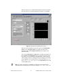
panel in Figure 18 is an example of the front panel for the
LabVIEW Simulation Interface Toolkit User Guide
30
ni.com
SineWave_driver_base VI. The Simulation Interface Toolkit created this
driver VI when you converted the SineWave model into a model DLL.
Figure 18. Front Panel of the SineWave_driver_base VI
The name of the model DLL automatically appears in the Model DLL
name text box. The Inport values correspond to the inputs of the
simulation model, and the Outport values display the outputs of the
simulation model.
You can use the Parameter and Value fields to modify the parameters for
the model DLL. In the Parameter text box, you must specify the path to
the parameter in the model DLL. In the Value field, you must enter the
value to which you want to set that parameter. For example, if you want to
set the amplitude of the generated sine wave in the model DLL to 2, you
enter SineWave/Sine Wave/Amplitude in the Parameter text box and
2 in the Value text box.
Note To specify a parameter in a model DLL, you must use the same path that the
Simulink model uses. Identify the parameter by specifying the model name/[subsystem
© National Instruments Corporation
31
LabVIEW Simulation Interface Toolkit User Guide
name]/block name/parameter name. If the block is in a subsystem of the simulation
model, then you need to specify the [subsystem name] in which the block is located.
After you enter the parameter information, click the SET PARAMETERS
button to set the parameter values in the model DLL. You can set the values
of all the parameters in the model DLL using the Parameter and Value
fields. The data type of the parameter that you specify has to be a
double-precision, floating-point number.
Note If you modify a parameter of an array data type, you can modify only one element
of the array at a time. To change the value of an element in the array, use the index values
to specify the element, then enter the new value.
Designing a Batch Simulation
Using the Simulation Interface Toolkit, you can run a batch simulation,
which is a series of simulations that have varying initial conditions or
parameter values. This section describes an example batch simulation
application created using the User Interface VIs. This application runs the
SineWave model, which you created in the Building a New Simulink Model
section, several times, each time with different initial parameter values for
the amplitude and frequency of the sine wave. This section describes how
to set the initial conditions on the front panel of the Batch Simulation VI
and teaches you more about the block diagram.
Setting the Initial Conditions for the Batch Simulation
Open the Batch Simulation VI located in the examples\Simulation
Interface\Batch Simulation directory to follow along.
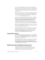
The front panel of the Batch Simulation VI, shown in Figure 19,
contains a Model path path control where you specify the path to the
model you want to run. In the Batch Simulation VI, the Model path text
box specifies the path to the SineWave model located in the examples\
SimulationInterface\SineWave directory.
Note The examples\SimulationInterface\SineWave directory provides solutions
to the exercises in this user guide. The folder contains examples of the Simulink model,
the LabVIEW VIs, and the model DLL you created.
LabVIEW Simulation Interface Toolkit User Guide
32
ni.com
Figure 19. Front Panel of the Batch Simulation VI
To set the initial parameter values, you can modify the values in the Array
of parameter values control. In this VI, the Array of parameter values
control contains three pairs of values for the frequency and amplitude
parameters. The Array of parameter values control indicates that the
Batch Simulation VI will run the SineWave model three times using the
values specified in this control. The Output chart displays the results of
this batch simulation.
Click the Run button to display the results of this batch simulation.
© National Instruments Corporation
33
LabVIEW Simulation Interface Toolkit User Guide
Understanding the Block Diagram of the Batch Simulation VI
Like the block diagram generated for the host VI, the block diagram for the
Batch Simulation VI has three parts—the code to initialize the batch
simulation, the code to set the parameter values, and the code to receive
indicator updates from the simulation model. However, the block diagram
for the Batch Simulation VI differs because instead of waiting for user
events to start the simulation and set parameters, this application performs
these tasks programmatically.
This Batch Simulation VI uses the User Interface VIs as subVIs. Refer to
the Simulation Interface Toolkit Help for information about the User
Interface VIs.
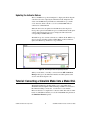
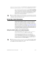
Initializing the Batch Simulation
The initialization code, shown in Figure 20, uses the SIT Initialize
Simulation VI to start the simulation. The SIT Initialize Simulation VI,
shown at left, initiates a connection to the SIT Server, which resides on the
computer specified by the hostname control. The port control indicates
the port number through which the Batch Simulation VI communicates
with the SineWave model. The Model path control specifies the path to
the Simulink model that you want to run.
Setting the Parameter Values
The For Loop contains the other two parts of the block diagram code—the
code that sets the parameter values and the code that updates the Output
indicator. The For Loop uses automatic indexing to determine the number
of times it executes. Specifically, the For Loop executes one time for every
element in the Array of parameter value control.
The code that sets the parameter values, also shown in Figure 20, uses the
SIT Register VI and the SIT Write VI, shown at left, to set the parameter
values in the SineWave model. Given the path to a sink and a reference to
the corresponding indicator, the SIT Register VI notifies the SIT Server
what values to display in the Output chart.
Given a path to a Simulink parameter, the SIT Write VI sets the initial value
of that parameter using the value specified in the Array of parameters
control. After setting the initial values for the simulation, the SIT Run
Simulation VI notifies the SIT Server to start running the simulation.
LabVIEW Simulation Interface Toolkit User Guide
34
ni.com
Figure 20. Block Diagram Code for Initializing the Simulation and
Setting Parameters Values
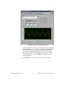
Updating the Output Indicator
The code that updates the indicators, shown in Figure 21, reads the data
from the Simulink parameters. The While Loop contains all the necessary
block diagram code for receiving the data from the Simulink model.
The While Loop contains the SIT Read VI and a Case structure. The
SIT Read VI, shown at left, receives a new value sent from the SIT Server
and determines the indicator in which to display the value. The Case
structure contains one case for each available indicator.
To configure the code for updating the indicators, you can create a Case
structure containing cases named according to the elements in the data
output of the SIT Read VI. The data output is a cluster containing
information such as the name of a LabVIEW indicator and the name of
the corresponding Simulink sink.
You wire an element of the data output to the selector terminal of the Case
structure. Then you name the cases in the Case structure according to the
element you chose to use. For example, when the Simulation Interface
Toolkit generates this code, it uses Simulink sink name, Sim Name, and the
LabVIEW indicator name, Ctl Name, in the data output to create the names
for the cases in the Case structure. So the names of the cases in the Case
© National Instruments Corporation
35
LabVIEW Simulation Interface Toolkit User Guide
structure are formatted as follows: model name/sink name – indicator
name.
Figure 21. Block Diagram Code for Updating Indicators
The SIT Read VI executes until the While Loop receives an indication from
the SIT Server that the simulation is complete. The result, for this example,
is a plot of three sine waves with different amplitudes and frequencies,
as shown in Figure 19.
Where to Go from Here
In addition to this user guide, the Simulation Interface Toolkit provides
example VIs that you can explore to learn more about creating simulation
models in LabVIEW.
Refer to the examples\simulation interface directory for examples
using the Simulation Interface VIs. The following two folders contain VIs
and examples used in this user guide.
•
SineWave folder—Contains solutions to the exercises in the Tutorial:
Creating a User Interface for a Simulink Model, Tutorial: Converting
a Simulink Model into a Model DLL, and Tutorial: Communicating
with the Model DLL sections.
•
Batch Simulation folder—Contains the Batch Simulation VI used
in the Designing a Batch Simulation section.
•
XY Graph folder—Contains an example of using the NIXYGraph
block in Simulink. The Lorenz UI VI uses the XYGraph in LabVIEW
to display the output data of the model.
LabVIEW Simulation Interface Toolkit User Guide
36
ni.com
LabVIEW includes extensive documentation for new and experienced
LabVIEW users. Refer to the LabVIEW Bookshelf for information about
LabVIEW and to access the LabVIEW help resources. Access the
LabVIEW Bookshelf by selecting Start»Programs»National
Instruments»LabVIEW»Search the LabVIEW Bookshelf.
© National Instruments Corporation
37
LabVIEW Simulation Interface Toolkit User Guide