1
Liebert® PDX™ and Liebert PCW™ Thermal Management Systems
User Manual–17-29kW, 5-8 Tons, Upflow and Downflow, 60Hz
TABLE OF CONTENTS
IMPORTANT SAFETY INSTRUCTIONS . . . . . . . . . . . . . . . . . . . . . . . . . . . . . . . . . . . . . . . . . . . . . . . .1
SAVE THESE INSTRUCTIONS . . . . . . . . . . . . . . . . . . . . . . . . . . . . . . . . . . . . . . . . . . . . . . . . .1
1.0
LIEBERT PDX AND LIEBERT PCW COMPONENTS AND NOMENCLATURE . . . . . . . . . . . . . . . .4
2.0
PRE-INSTALLATION GUIDELINES . . . . . . . . . . . . . . . . . . . . . . . . . . . . . . . . . . . . . . . . . . . . .9
2.1
Room Preparation. . . . . . . . . . . . . . . . . . . . . . . . . . . . . . . . . . . . . . . . . . . . . . . . . . . . . . . . . . . . 9
2.2
Air Distribution—Downflow Units . . . . . . . . . . . . . . . . . . . . . . . . . . . . . . . . . . . . . . . . . . . . . . 9
2.3
Air Distribution—Upflow Units . . . . . . . . . . . . . . . . . . . . . . . . . . . . . . . . . . . . . . . . . . . . . . . . 9
2.4
Connections and System Setup . . . . . . . . . . . . . . . . . . . . . . . . . . . . . . . . . . . . . . . . . . . . . . . . . 9
2.5
Operating Conditions . . . . . . . . . . . . . . . . . . . . . . . . . . . . . . . . . . . . . . . . . . . . . . . . . . . . . . . . 10
2.5.1
2.5.2
Cooling, Humidification and Dehumidification . . . . . . . . . . . . . . . . . . . . . . . . . . . . . . . . . . . . 10
Heating . . . . . . . . . . . . . . . . . . . . . . . . . . . . . . . . . . . . . . . . . . . . . . . . . . . . . . . . . . . . . . . . . . . . 10
3.0
LIEBERT PDX AND LIEBERT PCW DIMENSIONS AND WEIGHTS . . . . . . . . . . . . . . . . . . . . . 11
3.1
Floor Stand Dimensions. . . . . . . . . . . . . . . . . . . . . . . . . . . . . . . . . . . . . . . . . . . . . . . . . . . . . . 15
3.2
Plenum Dimensions . . . . . . . . . . . . . . . . . . . . . . . . . . . . . . . . . . . . . . . . . . . . . . . . . . . . . . . . . 17
4.0
EQUIPMENT INSPECTION AND HANDLING . . . . . . . . . . . . . . . . . . . . . . . . . . . . . . . . . . . . . . 18
4.1
Packaging Material . . . . . . . . . . . . . . . . . . . . . . . . . . . . . . . . . . . . . . . . . . . . . . . . . . . . . . . . . 18
SAFETY INFORMATION . . . . . . . . . . . . . . . . . . . . . . . . . . . . . . . . . . . . . . . . . . . . . . . . . . . . . 18
4.2
Unpacking the Unit . . . . . . . . . . . . . . . . . . . . . . . . . . . . . . . . . . . . . . . . . . . . . . . . . . . . . . . . . 19
4.2.1
4.2.2
4.2.3
Removing the Unit from the Skid With a Forklift . . . . . . . . . . . . . . . . . . . . . . . . . . . . . . . . . . 19
Removing the Unit from the Skid Using Rigging . . . . . . . . . . . . . . . . . . . . . . . . . . . . . . . . . . . 20
Moving the Unit With Piano Jacks . . . . . . . . . . . . . . . . . . . . . . . . . . . . . . . . . . . . . . . . . . . . . . 21
4.3
Placing the Unit on a Floor Stand . . . . . . . . . . . . . . . . . . . . . . . . . . . . . . . . . . . . . . . . . . . . . . 22
5.0
ELECTRICAL CONNECTIONS . . . . . . . . . . . . . . . . . . . . . . . . . . . . . . . . . . . . . . . . . . . . . . . 23
5.1
Standard Electrical Connections . . . . . . . . . . . . . . . . . . . . . . . . . . . . . . . . . . . . . . . . . . . . . . . 24
5.2
Supply Temperature Sensor . . . . . . . . . . . . . . . . . . . . . . . . . . . . . . . . . . . . . . . . . . . . . . . . . . 29
6.0
PIPING . . . . . . . . . . . . . . . . . . . . . . . . . . . . . . . . . . . . . . . . . . . . . . . . . . . . . . . . . . . . . . .30
6.1
Fluid Connections—Condensate and Humidifier . . . . . . . . . . . . . . . . . . . . . . . . . . . . . . . . . . 30
6.1.1
6.1.2
6.1.3
6.2
Condensate Piping—Field-Installed . . . . . . . . . . . . . . . . . . . . . . . . . . . . . . . . . . . . . . . . . . . . . 30
Humidifier Supply Water—Optional Infrared . . . . . . . . . . . . . . . . . . . . . . . . . . . . . . . . . . . . . 32
Humidifier Supply Water—Optional Steam Generating . . . . . . . . . . . . . . . . . . . . . . . . . . . . . 32
Refrigeration Piping—Air-Cooled Units . . . . . . . . . . . . . . . . . . . . . . . . . . . . . . . . . . . . . . . . . 32
6.2.1
6.2.2
6.2.3
6.2.4
Piping Guidelines—Air-Cooled Units . . . . . . . . . . . . . . . . . . . . . . . . . . . . . . . . . . . . . . . . . . . .
Scroll and Digital Scroll—Additional Oil Requirements . . . . . . . . . . . . . . . . . . . . . . . . . . . . .
Air-Cooled Condenser Without Liebert Lee-Temp™ System . . . . . . . . . . . . . . . . . . . . . . . . . .
Air Cooled Liebert MC™ Condensers with Liebert Lee-Temp™ “Flooded Condenser”
Head Pressure Control System . . . . . . . . . . . . . . . . . . . . . . . . . . . . . . . . . . . . . . . . . . . . . . . . .
33
34
35
40
6.3
Fluid Connections for Systems Using Water/Glycol and Chilled Water . . . . . . . . . . . . . . . . 42
7.0
PIPING SCHEMATICS . . . . . . . . . . . . . . . . . . . . . . . . . . . . . . . . . . . . . . . . . . . . . . . . . . . . . 43
8.0
CHECKLIST FOR COMPLETED INSTALLATION . . . . . . . . . . . . . . . . . . . . . . . . . . . . . . . . . . . 57
8.1
Moving and Placing Equipment . . . . . . . . . . . . . . . . . . . . . . . . . . . . . . . . . . . . . . . . . . . . . . . 57
i
8.2
Electrical . . . . . . . . . . . . . . . . . . . . . . . . . . . . . . . . . . . . . . . . . . . . . . . . . . . . . . . . . . . . . . . . . . 57
8.3
Piping . . . . . . . . . . . . . . . . . . . . . . . . . . . . . . . . . . . . . . . . . . . . . . . . . . . . . . . . . . . . . . . . . . . . 57
8.4
Other . . . . . . . . . . . . . . . . . . . . . . . . . . . . . . . . . . . . . . . . . . . . . . . . . . . . . . . . . . . . . . . . . . . . . 58
9.0
INITIAL STARTUP CHECKS AND COMMISSIONING PROCEDURE FOR WARRANTY
INSPECTION . . . . . . . . . . . . . . . . . . . . . . . . . . . . . . . . . . . . . . . . . . . . . . . . . . . . . . . . . . .59
9.1
Information for Warranty Inspection—Remove Power From Unit Disconnect . . . . . . . . . . 60
9.2
Startup Checks With Panels Removed and Main Disconnect Off . . . . . . . . . . . . . . . . . . . . . 60
9.3
Startup . . . . . . . . . . . . . . . . . . . . . . . . . . . . . . . . . . . . . . . . . . . . . . . . . . . . . . . . . . . . . . . . . . . 60
9.4
Commissioning Procedure With Panels On . . . . . . . . . . . . . . . . . . . . . . . . . . . . . . . . . . . . . . 62
10.0
MAINTENANCE . . . . . . . . . . . . . . . . . . . . . . . . . . . . . . . . . . . . . . . . . . . . . . . . . . . . . . . . . 63
10.1
Filters . . . . . . . . . . . . . . . . . . . . . . . . . . . . . . . . . . . . . . . . . . . . . . . . . . . . . . . . . . . . . . . . . . . . 64
9.2.1
Inspect and Record . . . . . . . . . . . . . . . . . . . . . . . . . . . . . . . . . . . . . . . . . . . . . . . . . . . . . . . . . . . 60
10.1.1 Filter Replacement Procedure—Downflow Units. . . . . . . . . . . . . . . . . . . . . . . . . . . . . . . . . . . 64
10.1.2 Filter Replacement Procedure—Upflow Units . . . . . . . . . . . . . . . . . . . . . . . . . . . . . . . . . . . . . 64
10.2
Blower Drive System—EC Fans . . . . . . . . . . . . . . . . . . . . . . . . . . . . . . . . . . . . . . . . . . . . . . . 64
10.2.1 Fan Impellers and Bearings. . . . . . . . . . . . . . . . . . . . . . . . . . . . . . . . . . . . . . . . . . . . . . . . . . . . 64
10.2.2 Protective Features . . . . . . . . . . . . . . . . . . . . . . . . . . . . . . . . . . . . . . . . . . . . . . . . . . . . . . . . . . 65
10.3
Removing EC Fans—Downflow Models . . . . . . . . . . . . . . . . . . . . . . . . . . . . . . . . . . . . . . . . . 66
10.4
Humidifier—Infrared . . . . . . . . . . . . . . . . . . . . . . . . . . . . . . . . . . . . . . . . . . . . . . . . . . . . . . . . 69
10.4.1 Cleaning Humidifier Pan and Float Switch . . . . . . . . . . . . . . . . . . . . . . . . . . . . . . . . . . . . . . . 69
10.4.2 Changing Humidifier Lamps . . . . . . . . . . . . . . . . . . . . . . . . . . . . . . . . . . . . . . . . . . . . . . . . . . . 70
10.5
Humidifier—Steam Generating . . . . . . . . . . . . . . . . . . . . . . . . . . . . . . . . . . . . . . . . . . . . . . . 70
10.6
Condensate Drain and Condensate Pump Systems . . . . . . . . . . . . . . . . . . . . . . . . . . . . . . . . 76
10.5.1 Replacing the Steam Generating Humidifier Canister . . . . . . . . . . . . . . . . . . . . . . . . . . . . . . 72
10.6.1 Condensate Drain . . . . . . . . . . . . . . . . . . . . . . . . . . . . . . . . . . . . . . . . . . . . . . . . . . . . . . . . . . . . 76
10.6.2 Condensate Pump . . . . . . . . . . . . . . . . . . . . . . . . . . . . . . . . . . . . . . . . . . . . . . . . . . . . . . . . . . . 76
10.7
Air-Cooled Condenser and Drycoolers. . . . . . . . . . . . . . . . . . . . . . . . . . . . . . . . . . . . . . . . . . . 77
10.8
Reheat—Electric Reheat . . . . . . . . . . . . . . . . . . . . . . . . . . . . . . . . . . . . . . . . . . . . . . . . . . . . . 77
10.9
Thermostatic Expansion Valve . . . . . . . . . . . . . . . . . . . . . . . . . . . . . . . . . . . . . . . . . . . . . . . . 77
10.9.1 Determine Suction Superheat . . . . . . . . . . . . . . . . . . . . . . . . . . . . . . . . . . . . . . . . . . . . . . . . . . 77
10.9.2 Adjust Superheat Setting with the TEV . . . . . . . . . . . . . . . . . . . . . . . . . . . . . . . . . . . . . . . . . . 77
10.10 Electronic Expansion Valve . . . . . . . . . . . . . . . . . . . . . . . . . . . . . . . . . . . . . . . . . . . . . . . . . . . 78
10.11 Compressor . . . . . . . . . . . . . . . . . . . . . . . . . . . . . . . . . . . . . . . . . . . . . . . . . . . . . . . . . . . . . . . . 78
10.11.1 Compressor Oil . . . . . . . . . . . . . . . . . . . . . . . . . . . . . . . . . . . . . . . . . . . . . . . . . . . . . . . . . . . . . .
10.11.2 Scroll and Digital Scroll Compressors . . . . . . . . . . . . . . . . . . . . . . . . . . . . . . . . . . . . . . . . . . . .
10.11.3 Compressor Replacement. . . . . . . . . . . . . . . . . . . . . . . . . . . . . . . . . . . . . . . . . . . . . . . . . . . . . .
10.11.4 Compressor Motor Burnout . . . . . . . . . . . . . . . . . . . . . . . . . . . . . . . . . . . . . . . . . . . . . . . . . . . .
10.11.5 Digital Compressor Unloading Solenoid(s) . . . . . . . . . . . . . . . . . . . . . . . . . . . . . . . . . . . . . . . .
10.11.6 Compressor Replacement Procedure . . . . . . . . . . . . . . . . . . . . . . . . . . . . . . . . . . . . . . . . . . . . .
78
78
78
78
79
79
10.12 Facility Fluid and Piping Maintenance. . . . . . . . . . . . . . . . . . . . . . . . . . . . . . . . . . . . . . . . . . 79
10.13 Glycol Solution Maintenance . . . . . . . . . . . . . . . . . . . . . . . . . . . . . . . . . . . . . . . . . . . . . . . . . . 79
10.14 Motorized Ball Valve . . . . . . . . . . . . . . . . . . . . . . . . . . . . . . . . . . . . . . . . . . . . . . . . . . . . . . . . 80
10.15 Drycooler Settings . . . . . . . . . . . . . . . . . . . . . . . . . . . . . . . . . . . . . . . . . . . . . . . . . . . . . . . . . . 81
11.0
HVAC MAINTENANCE CHECKLIST . . . . . . . . . . . . . . . . . . . . . . . . . . . . . . . . . . . . . . . . . . . 82
ii
FIGURES
Figure 1
Figure 2
Figure 3
Figure 4
Figure 5
Figure 6
Figure 7
Figure 8
Figure 9
Figure 10
Figure 11
Figure 12
Figure 13
Figure 14
Figure 15
Figure 16
Figure 17
Figure 18
Figure 19
Figure 20
Figure 21
Figure 22
Figure 23
Figure 24
Figure 25
Figure 26
Figure 27
Figure 28
Figure 29
Figure 30
Figure 31
Figure 32
Figure 33
Figure 34
Figure 35
Figure 36
Figure 37
Figure 38
Figure 39
Figure 40
Figure 41
Figure 42
Figure 43
Figure 44
Figure 45
Component locations—Downflow, Liebert PDX . . . . . . . . . . . . . . . . . . . . . . . . . . . . . . . . . . . . . . . . 4
Component locations—Downflow, Liebert PCW . . . . . . . . . . . . . . . . . . . . . . . . . . . . . . . . . . . . . . . . 5
Component locations—Upflow, Liebert PDX . . . . . . . . . . . . . . . . . . . . . . . . . . . . . . . . . . . . . . . . . . 6
Component locations—Upflow, Liebert PCW . . . . . . . . . . . . . . . . . . . . . . . . . . . . . . . . . . . . . . . . . . 7
Cabinet and floor planning dimensions—downflow . . . . . . . . . . . . . . . . . . . . . . . . . . . . . . . . . . . . 12
Cabinet and floor planning dimensions—front discharge, downflow . . . . . . . . . . . . . . . . . . . . . . 13
Cabinet and floor planning dimensions—Upflow . . . . . . . . . . . . . . . . . . . . . . . . . . . . . . . . . . . . . 14
Floor stand dimensions—Downflow and upflow, front return floor stands. . . . . . . . . . . . . . . . . . 15
Floor stand dimensions—Upflow, rear return floor stands . . . . . . . . . . . . . . . . . . . . . . . . . . . . . . 16
Plenum dimensions—Upflow . . . . . . . . . . . . . . . . . . . . . . . . . . . . . . . . . . . . . . . . . . . . . . . . . . . . . . 17
Equipment recommended for handling Liebert PDX and Liebert PCW . . . . . . . . . . . . . . . . . . . . 18
Removing packaging . . . . . . . . . . . . . . . . . . . . . . . . . . . . . . . . . . . . . . . . . . . . . . . . . . . . . . . . . . . . . 19
Remove the unit from the skid with a forklift . . . . . . . . . . . . . . . . . . . . . . . . . . . . . . . . . . . . . . . . . 20
Remove the unit from the skid with rigging . . . . . . . . . . . . . . . . . . . . . . . . . . . . . . . . . . . . . . . . . . 21
Moving the unit with piano jacks. . . . . . . . . . . . . . . . . . . . . . . . . . . . . . . . . . . . . . . . . . . . . . . . . . . 22
Electrical field connections—Upflow and downflow models. . . . . . . . . . . . . . . . . . . . . . . . . . . . . . 24
CANbus communication and interlock connections between Liebert PDX and Liebert MC™
(premium . . . . . . . . . . . . . . . . . . . . . . . . . . . . . . . . . . . . . . . . . . . . . . . . . . . . . . . . . . . . . . . . . . . . . . 26
Electrical field connections for Liebert iCOM®—Downflow models . . . . . . . . . . . . . . . . . . . . . . . 27
Electrical field connections for Liebert iCOM®—Upflow models . . . . . . . . . . . . . . . . . . . . . . . . . . 28
Gravity drain . . . . . . . . . . . . . . . . . . . . . . . . . . . . . . . . . . . . . . . . . . . . . . . . . . . . . . . . . . . . . . . . . . . 31
Piping schematic—Air-cooled models . . . . . . . . . . . . . . . . . . . . . . . . . . . . . . . . . . . . . . . . . . . . . . . 43
Piping schematic—Water/glycol models . . . . . . . . . . . . . . . . . . . . . . . . . . . . . . . . . . . . . . . . . . . . . 44
Piping schematic—GLYCOOL models. . . . . . . . . . . . . . . . . . . . . . . . . . . . . . . . . . . . . . . . . . . . . . . 45
Piping schematic, chilled water units . . . . . . . . . . . . . . . . . . . . . . . . . . . . . . . . . . . . . . . . . . . . . . . 46
Optional piping schematic for Econ-O-Coil . . . . . . . . . . . . . . . . . . . . . . . . . . . . . . . . . . . . . . . . . . . 47
Primary connection locations—Liebert PDX downflow, air-cooled models . . . . . . . . . . . . . . . . . . 48
Primary connection locations—Liebert PDX downflow, air-cooled, front discharge models . . . . 49
Primary connection locations, Liebert PDX downflow, water/glycol/GLYCOOL-cooled
models . . . . . . . . . . . . . . . . . . . . . . . . . . . . . . . . . . . . . . . . . . . . . . . . . . . . . . . . . . . . . . . . . . . . . . . . 50
Primary connection locations, Liebert PDX downflow water/glycol/GLYCOOL, front
discharge models . . . . . . . . . . . . . . . . . . . . . . . . . . . . . . . . . . . . . . . . . . . . . . . . . . . . . . . . . . . . . . . . 51
Primary connection locations, Liebert PCW chilled water downflow models . . . . . . . . . . . . . . . . 52
Primary connection locations, Liebert PCW downflow, front discharge . . . . . . . . . . . . . . . . . . . . 53
Primary connection locations, Liebert PDX air-cooled upflow models. . . . . . . . . . . . . . . . . . . . . . 54
Primary connection locations, Liebert PDX upflow, water/glycol/GLYCOOL models . . . . . . . . . 55
Primary connection locations, Liebert PCW chilled water upflow models . . . . . . . . . . . . . . . . . . 56
Remove the humidifier drain line . . . . . . . . . . . . . . . . . . . . . . . . . . . . . . . . . . . . . . . . . . . . . . . . . . 67
Remove humidifier high-limit wires . . . . . . . . . . . . . . . . . . . . . . . . . . . . . . . . . . . . . . . . . . . . . . . . 67
Humidifier electric box location . . . . . . . . . . . . . . . . . . . . . . . . . . . . . . . . . . . . . . . . . . . . . . . . . . . . 68
Bolt and panel removal. . . . . . . . . . . . . . . . . . . . . . . . . . . . . . . . . . . . . . . . . . . . . . . . . . . . . . . . . . . 68
Correct float switch orientation . . . . . . . . . . . . . . . . . . . . . . . . . . . . . . . . . . . . . . . . . . . . . . . . . . . . 70
Infrared humidifier lamps . . . . . . . . . . . . . . . . . . . . . . . . . . . . . . . . . . . . . . . . . . . . . . . . . . . . . . . . 70
Steam generating humidifier canister . . . . . . . . . . . . . . . . . . . . . . . . . . . . . . . . . . . . . . . . . . . . . . . 71
Removing the old canister . . . . . . . . . . . . . . . . . . . . . . . . . . . . . . . . . . . . . . . . . . . . . . . . . . . . . . . . 73
Drain valve assembly . . . . . . . . . . . . . . . . . . . . . . . . . . . . . . . . . . . . . . . . . . . . . . . . . . . . . . . . . . . . 74
Canister plugs . . . . . . . . . . . . . . . . . . . . . . . . . . . . . . . . . . . . . . . . . . . . . . . . . . . . . . . . . . . . . . . . . . 74
Circuit board diagram. . . . . . . . . . . . . . . . . . . . . . . . . . . . . . . . . . . . . . . . . . . . . . . . . . . . . . . . . . . . 76
iii
TABLES
Table 1
Table 2
Table 3
Table 4
Table 5
Table 6
Table 7
Table 8
Table 9
Table 10
Table 11
Table 12
Table 13
Table 14
Table 15
Table 16
Table 17
Table 18
Table 19
Table 20
Table 21
Table 22
Shipping dimensions—Liebert PDX and Liebert PCW, domestic and export . . . . . . . . . . . . . . . .
Shipping weights—approximate . . . . . . . . . . . . . . . . . . . . . . . . . . . . . . . . . . . . . . . . . . . . . . . . . . .
Weights for downflow, Liebert PDX and Liebert PCW, lb. (kg) . . . . . . . . . . . . . . . . . . . . . . . . . . .
Weights for downflow, Liebert PDX and Liebert PCW, lb. (kg) . . . . . . . . . . . . . . . . . . . . . . . . . . .
Approximate weights, upflow models, lb. (kg). . . . . . . . . . . . . . . . . . . . . . . . . . . . . . . . . . . . . . . . .
Floor stand height—Downflow. . . . . . . . . . . . . . . . . . . . . . . . . . . . . . . . . . . . . . . . . . . . . . . . . . . . .
Upflow unit plenum dimensions . . . . . . . . . . . . . . . . . . . . . . . . . . . . . . . . . . . . . . . . . . . . . . . . . . .
Recommended refrigerant line sizes - OD copper (inches)* . . . . . . . . . . . . . . . . . . . . . . . . . . . . . .
Indoor unit approximate refrigerant charge for R-410A . . . . . . . . . . . . . . . . . . . . . . . . . . . . . . . .
Condenser refrigerant charge. . . . . . . . . . . . . . . . . . . . . . . . . . . . . . . . . . . . . . . . . . . . . . . . . . . . . .
Additional oil required per refrigerant charge . . . . . . . . . . . . . . . . . . . . . . . . . . . . . . . . . . . . . . . .
Interconnecting piping refrigerant charge . . . . . . . . . . . . . . . . . . . . . . . . . . . . . . . . . . . . . . . . . . .
Target subcooling for ambient outdoor temperature . . . . . . . . . . . . . . . . . . . . . . . . . . . . . . . . . . .
Difference in subcooling measurements—Indoor minus outdoor. . . . . . . . . . . . . . . . . . . . . . . . . .
Liquid pressure and temperature chart . . . . . . . . . . . . . . . . . . . . . . . . . . . . . . . . . . . . . . . . . . . . .
Filters, number and size . . . . . . . . . . . . . . . . . . . . . . . . . . . . . . . . . . . . . . . . . . . . . . . . . . . . . . . . . .
Humidifier canister part numbers . . . . . . . . . . . . . . . . . . . . . . . . . . . . . . . . . . . . . . . . . . . . . . . . . .
Steam generating humidifier status lamps: causes, corrective action. . . . . . . . . . . . . . . . . . . . . .
Steam generating humidifier troubleshooting guide . . . . . . . . . . . . . . . . . . . . . . . . . . . . . . . . . . .
Compressor oil types . . . . . . . . . . . . . . . . . . . . . . . . . . . . . . . . . . . . . . . . . . . . . . . . . . . . . . . . . . . . .
Water/glycol system conditions requiring optional settings for aquastats . . . . . . . . . . . . . . . . . .
Aquastat settings—two-fan through four-fan drycoolers . . . . . . . . . . . . . . . . . . . . . . . . . . . . . . . .
iv
11
11
12
13
14
15
17
33
33
34
34
34
36
38
38
64
73
75
75
78
81
81
Important Safety Instructions
IMPORTANT SAFETY INSTRUCTIONS
SAVE THESE INSTRUCTIONS
This manual contains important safety instructions that should be followed during the installation
and maintenance of the Liebert PDX and Liebert PCW. Read this manual thoroughly before
attempting to install or operate this unit.
Only qualified personnel should move, install or service this equipment.
Adhere to all warnings, cautions and installation, operating and safety instructions on the unit and in
this manual. Follow all operating and user instructions.
! WARNING
Arc flash and electric shock hazard. Can cause injury and death.
Open all local and remote electric power supply disconnect switches, verify with a voltmeter
that power is Off and wear appropriate personal protective equipment per NFPA 70E before
working within the electric control enclosure.
Open all local and remote electric power disconnect switches and verify with a voltmeter that
power is Off before working within the various component electric connection enclosures.
Before proceeding with installation, read all instructions, verify that all the parts are included
and check the nameplate to be sure the voltage matches available utility power.
The Liebert iCOM® microprocessor does not isolate power from the unit, even in the Unit Off
mode.
Customer must provide earth ground to unit, per NEC, CEC and local codes, as applicable.
Before proceeding with installation, read all instructions, verify that all the parts are included
and check the nameplate to be sure the voltage matches available utility power.
The Liebert iCOM microprocessor does not isolate power from the unit, even in the Unit Off
mode. Some internal components require and receive power even during the Unit Off mode of
Liebert iCOM control.
The factory-supplied optional disconnect switch is inside the unit. The line side of this switch
contains live high-voltage.
The only way to ensure that there is NO voltage inside the unit is to install and open a remote
disconnect switch. Refer to unit electrical schematic.
Follow all local codes.
! WARNING
Risk of explosive discharge from high-pressure refrigerant. Can cause injury or death.
This unit contains fluids and/or gases under high pressure. Relieve pressure before working
with piping.
! WARNING
Risk of refrigerant system rupture or explosion from overpressurization. Can cause
equipment damage, injury or death.
Do not exceed the design pressure rating marked on the unit nameplate. This unit contains
fluids and gases under high pressure. Relieve pressure before working with piping.
Local building or plumbing codes may require installing a fusible plug or other type of
pressure relief device in the system.
1
Liebert® PDX™ and Liebert PCW™
Important Safety Instructions
! WARNING
Risk of contact with high-speed rotating fan blades. Can cause injury or death.
Open all local and remote electric power supply disconnect switches, verify with a voltmeter
that power is Off and verify that all fans have stopped rotating before working within the unit
cabinet.
Do not operate unit with any or all cabinet panels removed. Do not operate upflow units
without installing a plenum, ductwork or guard over the blower opening(s) on the top surface
of the unit cabinet.
Ductwork must be connected to the blower(s), or a plenum must be installed on the blower
deck for protection from rotating blower wheel(s) on upflow units.
! WARNING
Risk of improper handling of top heavy unit. Can cause unit to fall over, resulting in
equipment damage, serious injury or death.
Read all instructions before attempting to move, lift, remove packaging from or preparing
unit for installation.
! CAUTION
Risk of contact with hot surfaces. Can cause injury.
The compressors, refrigerant discharge lines, humidifiers and reheats are extremely hot
during unit operation. Allow sufficient time for them to cool before working within the unit
cabinet. Use extreme caution and wear protective gloves and arm protection when working on
or near hot compressors, discharge lines, humidifiers and reheats.
! CAUTION
Risk of contact with sharp edges, splinters and exposed fasteners. Can cause injury.
Only properly trained and qualified personnel wearing appropriate safety headgear, gloves,
shoes and glasses should attempt to move the unit, lift it, remove packaging from or prepare
the unit for installation.
! CAUTION
Risk of handling heavy and lengthy parts. Can cause personal injury and equipment damage.
Cabinet panels can exceed 5ft. (1.5m) in length and weigh more than 35 lb. (15.9kg). Follow
relevant OSHA lifting recommendations and consider using a two-person lift for safe and
comfortable removal and installation of cabinet panels. Only properly trained and qualified
personnel wearing appropriate safety headgear, gloves and shoes should attempt to remove or
install cabinet panels.
NOTE
The Liebert indoor cooling unit has a factory-installed high-pressure safety switch in the high
side refrigerant circuit. A pressure relief valve is provided with Liebert Lee-Temp™ condensers.
NOTICE
Risk of clogged or leaking drain lines. Can cause equipment and building damage.
This unit requires a water drain connection. Drain lines must be inspected regularly and
maintenance must be performed to ensure that drain water runs freely through the drain
system and that lines are clear and free of obstructions and in good condition with no visible
sign of damage or leaks. This unit may also require an external water supply to operate.
Improper installation, application and service practices can result in water leakage from the
unit. Water leakage can result in severe property damage and loss of critical data center
equipment.
Do not locate unit directly above any equipment that could sustain water damage.
Emerson recommends installing a monitored fluid detection system to immediately discover
and report coolant fluid system and condensate drain line leaks.
Liebert® PDX™ and Liebert PCW™
2
Important Safety Instructions
NOTICE
Risk of a leaking coolant fluid system due to freezing and/or corrosion can cause equipment
and very expensive building damage.
Cooling coils, heat exchangers and piping systems that are connected to open cooling towers
or other open water/glycol systems are at high risk of freezing and premature corrosion.
Fluids in these systems must contain the proper antifreeze and inhibitors to prevent freezing
and premature coil, piping and heat exchanger corrosion. The water or water/glycol solution
must be analyzed by a competent local water treatment specialist before startup to establish
the inhibitor and antifreeze solution requirement and at regularly scheduled intervals
throughout the life of the system to determine the pattern of inhibitor depletion.
The complexity of water/glycol solution condition problems and the variations of required
treatment programs make it extremely important to obtain the advice of a competent and
experienced water treatment specialist and follow a regularly scheduled coolant fluid system
maintenance program.
Read and follow individual unit installation instructions for precautions regarding fluid
system design, material selection and use of field-provided devices. Liebert systems contain
iron and copper alloys that require appropriate corrosion protection. It is important to have
the system running with flow through exchangers maintained at initial system fill for 24 to 48
hours depending on size and system configuration.
Water chemistry varies greatly by location, as do the required additives, called inhibitors,
that reduce the corrosive effect of the fluids on the piping systems and components. The
chemistry of the water used must be considered, because water from some sources may
contain corrosive elements that reduce the effectiveness of the inhibited formulation.
Sediment deposits prevent the formation of a protective oxide layer on the inside of the
coolant system components and piping. The water/coolant fluid must be treated and
circulating through the system continuously to prevent the buildup of sediment deposits and
or growth of sulfate reducing bacteria.
Proper inhibitor maintenance must be performed in order to prevent corrosion of the system.
Consult glycol manufacturer for testing and maintenance of inhibitors.
Commercial ethylene glycol, when pure, is generally less corrosive to the common metals of
construction than water itself. It will, however, assume the corrosivity of the water from
which it is prepared and may become increasingly corrosive with use if not properly inhibited.
NOTICE
Risk of no-flow condition. Can cause equipment damage.
Do not leave the unit in a no-flow condition. Idle fluid allows the collection of sediment that
prevents the formation of a protective oxide layer on the inside of tubes. Keep unit switched
On and system pump operating continuously.
NOTICE
Risk of damage from forklift. Can cause unit damage.
Keep tines of the forklift level and at a height suitable to fit below the skid and/or unit to
prevent exterior and/or underside damage.
NOTICE
Risk of improper storage. Can cause unit damage.
Keep the Liebert PDX and Liebert PCW upright, indoors and protected from dampness,
freezing temperatures and contact damage.
Agency Listed
Standard 60Hz units are CSA certified to the harmonized U.S. and Canadian product safety standard
CSA C22.2 No 236/UL 1995 for Heating and Cooling Equipment and are marked with the CSA c-us
logo.
3
Liebert® PDX™ and Liebert PCW™
Liebert PDX and Liebert PCW Components and Nomenclature
1.0
LIEBERT PDX AND LIEBERT PCW COMPONENTS AND NOMENCLATURE
Figure 1
Component locations—Downflow, Liebert PDX
1
2
3
4
10
9
8
11
7
5
6
Front View
1. Filter
2. Serial Tag
3. Electric Box
4. Liebert iCOM
5. EC Fan
6. Infrared Humidifier, optional
7. Compressor
8. Evaporator Coil
9. Plate Condenser, optional
10. Disconnect
11.Smoke Detector, optional
12. Reheat, optional
13. Econ-O-Coil Valve GLYCOOL/Dual Cooling, optional
Liebert® PDX™ and Liebert PCW™
4
12
13
Rear View
DPN003004
Rev. 0
Liebert PDX and Liebert PCW Components and Nomenclature
Figure 2
Component locations—Downflow, Liebert PCW
1
2
3
4
9
10
8
7
5
6
Front View
1. Filter
2. Serial Tag
3. Electric Box
4. Liebert iCOM
5. Infrared Humidifier, optional
6. EC Fan
7. Chilled Water Valve
8. Disconnect
9. Chilled Water Coil
10. Smoke Detector, optional
11. Reheat, optional
11
DPN003020
Rev. 0
5
Rear View
Liebert® PDX™ and Liebert PCW™
Liebert PDX and Liebert PCW Components and Nomenclature
Figure 3
Component locations—Upflow, Liebert PDX
1
2
3
4
10
9
6
8
5
7
Front View
1. EC Fan
2. Serial Tag
3. Electric Box
4. Liebert iCOM
5. Infrared Humidifier, optional
6. Filter, partial filter shown for clarity
7. Compressor
8. Plate Condenser, optional
9. Disconnect
10. Evaporator Coil
11. Econ-O-Coil Valve GLYCOOL/Dual Cooling, optional
12. Reheat, optional
13. Condensate Pump, optional
14. Smoke Detector, optional
DPN003005
Rev. 0
11
12
14
13
Rear View
Liebert® PDX™ and Liebert PCW™
6
Liebert PDX and Liebert PCW Components and Nomenclature
Figure 4
Component locations—Upflow, Liebert PCW
1
2
3
4
10
9
5
6
7
8
11
FRONT VIEW
1. EC Fan
2. Serial Tag
3. Electric Box
4. Liebert iCOM®
5. Condensate Pump, optional
6. Infrared Humidifier, optional
7. Chilled Water Valve
8. Filter (partial filter shown for clarity)
9. Disconnect
10. Chilled Water Coil
11. Reheat, optional
12. Smoke Detector, optional
12
REAR VIEW
7
DPN003021
Rev. 0
Liebert® PDX™ and Liebert PCW™
Liebert PDX and Liebert PCW Components and Nomenclature
Model Number – Part 1/2
Model Details
Part 2/2
1
2
3
4
5
6
7
8
9
10
11
12
13
14
15
16
17
18
19
20
21
22
23
24
25
P
X
0
2
9
U
A
1
A
D
H
E
2
8
0
1
P
L
5
F
P
A
1
2
3
Digit 1, 2 = Product Family
Digit 14 = Air filter
PX = Liebert PDX (DX)
8 = MERV 8, 2" (with Clogged Filter Sensor)
PW = Liebert PCW (CW)
9 = MERV 11, 2" (with Clogged Filter Sensor)
Digit 3, 4, 5 = Cooling Capacity, kW
Digit 15 Coil, Valve & Pressure Options
Nominal Sensible Capacity, kW
0 = Air-Cooled, no valve
Digit 6 = Air Discharge
1 = Standard Pressure, 2 Way MBV (condenser valve)
U = Upflow with front air return
2 = High Pressure, 2 Way MBV (condenser valve) 1
C = Upflow with bottom air return
7 = Standard Pressure, 3 Way MBV (condenser valve)
D = Downflow - discharge into raised floor
8 = High Pressure, 3 Way MBV (condenser valve) 1
H = Downflow with front air discharge
B = Standard Pressure, Dual Cool (Air-cooled)
1 = Downflow with front and right side discharge
E = High Pressure, Dual Cool (Air-Cooled)
2 = Downflow with front and right and left side discharge
Digit 16 = Enclosure options
3 = Downflow with front and left side discharge
1 = No options
Digit 7 = System Type
C = Double-skin panels
A = Air-Cooled
3 = IBC/OSHPD bracing 2
W = Water/Glycol-Cooled
8 = Double skin panels and IBC/OSHPD 2
G = GLYCOOL
Digit 17 = High-Voltage Options
C = Chilled Water
M = Locking Disconnect (65kA) No condensate pump
D = Dual Cool (Air-Cooled + FC Coil - 3-Way FC Valve)
P = Locking Disconnect (65kA) with condensate pump
H = Dual Cool (Water/Glycol-Cooled + FC Coil - 3-Way FC Valve)
Digit 18 = Low-Voltage Option Packages
2 = Dual Cool (Air-Cooled + FC Coil - 2Way FC Valve)
0 = None
3 = Dual Cool (Water/Glycol-Cooled + FC Coil - 2-Way FC Valve)
L = Terminal Package
Digit 8 = Airflow (fan type)
H = Reheat & Humidifier Lockout
1 = EC plug fans
R = Remote Humidity Contact
Digit 9 = Power Supply
C = Term. Pkg. and R/H lockout
A = 460V / 3ph / 60Hz
D = Term. Pkg. and remote humidifier contact
B = 575V / 3ph / 60Hz
E = Term. Pkg. and R/H lockout and remote humidifier contact
C = 208V / 3ph / 60Hz
F = Remote humidifier contact plus R/H lockout
D = 230V / 3ph / 60Hz
Digit 19 = Monitoring Cards
2 = 380 / 3ph / 60Hz
0 = No Cards
U = One Liebert IntelliSlot™ IS-UNITY-DP Card
Digit 10 = Cooling System
S = Standard Scroll w/TXV ( no sound jacket)
C = One Liebert IntelliSlot IS-485EXI
D = Digital Scroll w/TXV (no sound jacket)
6 = One IS-Unity-DP and IS-485EXI
P = Digital Scroll w/EEV (no sound jacket) 3
7 = Two Liebert IntelliSlot™ IS-UNITY-DP Cards
8 - Digital Scroll with TXV & Sound Jacket
Digit 20 = Sensors
9 - Digital Scroll with EEV & Sound Jacket 3
0 = None
2 = Chilled Water - 2-Way Standard Pressure
S = Smoke Sensor
3 = Chilled Water - 3-Way Standard Pressure
H = High-Temperature Sensor
1 = Chilled Water - 2-Way High Pressure
F = Smoke and High-Temperature Sensors
T = Chilled Water - 3-Way High Pressure
C = Compressor Overload Sensor
Digit 11 = Humidification
A = Smoke and Compressor Overload Sensors
0 = No humidifier
D = High-Temperature Compressor Overload Sensors
H = Infrared Humidifier
K = Smoke, High-Temperature Compressor Sensors
S = Steam Gen Canister Humidifier
Digit 21 = Packaging
Digit 12 = Display
P = Domestic
E = Large Display w/ Supply Air Sensor
C = Wood Crate Export
Digit 13 = Reheat
Digit 22 = Configuration code
0 = No reheat
A = No SFA’s (An Alpha except S)
2 = Electric reheat (2-Stage)
S = SFA
4 = Hot Water Reheat (CW only)
Digit 23-25 = Factory Configuration Number
1.
2.
3.
Note: The 14-digit model number consists of the first 10 digits and last
four digits of the configuration number.
Liebert® PDX™ and Liebert PCW™
8
High-pressure MBV also results in high pressure FC valve.
Consult Factory for IBC/OSPHD option availability.
Consult Factory for EEV option availability
Pre-Installation Guidelines
2.0
PRE-INSTALLATION GUIDELINES
2.1
Room Preparation
• Verify that the floor is level, solid and sufficient to support the unit. See Table 2 for unit weights.
• Confirm that the room is properly insulated and has a sealed vapor barrier.
• For proper humidity control, keep outside or fresh air to an absolute minimum (less than 5% of
total air circulated in the room).
• Do not install a Liebert PDX and Liebert PCW in an alcove or at the end of a long, narrow room.
• Install the units as close as possible to the largest heat load.
• Allow at least the minimum recommended clearances for maintenance and service. See
Figures 5 through 22 for dimensions.
• Emerson recommends installing an under-floor water detection system. Contact your local
Emerson representative for information.
2.2
Air Distribution—Downflow Units
• Verify that the raised floor has been properly sized for the unit’s airflow and the room is free of
airflow restrictions.
• Perforated floor tiles in the raised floor should ensure minimal pressure loss.
• The raised floor must provide 7-1/2" (191mm) of clearance.
• Ensure that there is adequate clearance above the unit for service, such as replacing filters.
2.3
Air Distribution—Upflow Units
For in-room applications with supply and return grilles, several feet of clearance must be maintained
at the intake and discharge of the unit.
2.4
Connections and System Setup
• Plan the routing of wiring, piping and ductwork to the unit. See Figures 16 through 34 for unit
connection locations.
• Water/glycol and GLYCOOL units utilizing a drycooler may require an optional aquastat setting.
See Tables 21 and 22 for aquastat setting guidelines. Applications with the optional stat setting
require field piping to be insulated to prevent condensation.
• The unit requires a drain, which must comply with all applicable codes. This drain line may
contain boiling water. See 6.1.1 - Condensate Piping—Field-Installed for details.
• Three-phase electrical service is required for all models. Electrical service must conform to
national and local electrical codes. See equipment nameplate for details.
• If seismic requirements apply, consult your local Emerson representative for information about a
seismic-rated floor stand.
NOTE
Seal openings around piping and electrical connection to prevent air leakage. Failure to do so
could reduce the unit’s cooling performance.
9
Liebert® PDX™ and Liebert PCW™
Pre-Installation Guidelines
2.5
Operating Conditions
2.5.1
Cooling, Humidification and Dehumidification
The Liebert PDX and Liebert PCW must be operated in a conditioned space within the operating
envelope ASHRAE recommends for data centers: Maximum dew point of 59°F (15°C).
Operating outside this envelope can decrease equipment reliability.
Return air to the Liebert PDX and Liebert PCW must be no cooler than the ASHRAE
recommendation of 68°F (20°C) DB and 40% RH or minimum WB of 54°F (12.2°C) for proper unit
operation. Operating below this can decrease equipment reliability.
Refer to ASHRAE’s publication, “Thermal Guidelines for Data Processing Environments.”
2.5.2
Heating
The Liebert PDX and Liebert PCW are qualified for heating-only operation at temperatures not
exceeding 80°F (27°C).
Liebert® PDX™ and Liebert PCW™
10
Liebert PDX and Liebert PCW Dimensions and Weights
3.0
LIEBERT PDX AND LIEBERT PCW DIMENSIONS AND WEIGHTS
Table 1
Shipping dimensions—Liebert PDX and Liebert PCW, domestic and export
Lx W x H, in. (mm)
Domestic
Export
Model Number
PX018, PX023, PX029,
PW017, PW029
Table 2
45 x 45 x 85
(1143 x1143 x 2159)
45 x 45 x 86
(1143 x1143 x 2184)
Shipping weights—approximate
Model #
Cooling Type
Air
PX018
PX023
PX029
PW017
PW029
Air with Dual Cool
Domestic, lb. (kg)
Export, lb. (kg)
780 (353.8)
884 (400.9)
860 (390)
964 (437.2)
W/G
800 (362.8)
904 (410)
Water/Glycol with Dual Cool & GLYCOOL
880 (399.2)
984 (446.3)
Air
810 (367.4)
914 (414.6)
Air with Dual Cool
900 (408.2)
1004 (455.4)
W/G
830 (376.5)
934 (423.6)
Water/Glycol with Dual Cool & GLYCOOL
920 (417.3)
1024 (464.5)
CW
710 (322.0)
814 (369.2)
11
Liebert® PDX™ and Liebert PCW™
Liebert PDX and Liebert PCW Dimensions and Weights
Figure 5
Cabinet and floor planning dimensions—downflow
34-5/8"
(879mm)
33-1/8"
(842mm)
1 1/2"
(38mm)
TOP VIEW
Liebert
Precision Cooling
34"
(864mm)
77- 9/16"
(1970mm)
Shaded area indicates a
recommended minimum
clearance for component access.
34-1/2"
(876mm)
FRONT VIEW
Table 3
34"
(864mm)
DPN002936
Rev. 2
Weights for downflow, Liebert PDX and Liebert PCW, lb. (kg)
Liebert PDX Model No.
PX018-023
PX029
Air Cooled
670 (304)
700 (317)
Air Cooled w/Dual Cool
750 (340)
790 (358)
Water/Glycol
690 (313)
720 (327)
GLYCOOL or Water/Glycol w/Dual Cool
770 (349)
810 (367)
Liebert PCW Model No.
PW017-029
Chilled Water
600 (272)
Source: DPN002936, Rev. 2
Liebert® PDX™ and Liebert PCW™
12
Liebert PDX and Liebert PCW Dimensions and Weights
Figure 6
Cabinet and floor planning dimensions—front discharge, downflow
33-1/8"
(842mm)
34-5/8"
(879mm)
2
26-1/8"
(663mm)
5-1/2"
(139mm)
TOP
1-1/2"
(38mm)
34"
(864mm)
34"
(864mm)
RIGHT ISO VIEW
1
77-9/16"
(1970mm)
9"
(226mm)
26-1/8"
(663mm)
10 3/4" (273mm)
34"
(864mm)
26-9/16"
(674mm)
34-1/2"
(876mm)
34"
(864mm)
3
FRONT
1
LEFT ISO VIEW
1
Shaded area indicates the recommended minimum clearance for component access.
2
Optional opening for units with right side discharge or right and left side discharge.
3
Optional opening for units with left side discharge or right and left side discharge
Table 4
DPN002944
Rev. 0
Weights for downflow, Liebert PDX and Liebert PCW, lb. (kg)
Liebert PDX Model No.
PX018-023
PX029
Air-Cooled
670 (304)
700 (317)
Air-Cooled w/Dual Cool
750 (340)
790 (358)
Water/Glycol
690 (313)
720 (327)
GLYCOOL or Water/Glycol w/Dual Cool
770 (349)
810 (367)
Liebert PCW Model No.
PW017-029
Chilled Water
600 (272)
Source: DPN002944, Rev. 0
13
Liebert® PDX™ and Liebert PCW™
Liebert PDX and Liebert PCW Dimensions and Weights
Figure 7
Cabinet and floor planning dimensions—Upflow
34-11/16"
(881mm)
32-15/16"
(836mm)
1-3/4"
(45mm)
Top View
34"
(864mm)
OFF
77-5/8"
(1971mm)
Shaded area indicates a
recommended minimum
clearance for component
access.
34-1/2"
(876mm)
Approximate weights, upflow models, lb. (kg)
Liebert PDX Model No.
PX018-023
PX029
Air-Cooled
670 (304)
700 (317)
Air-Cooled w/Dual Cool
750 (340)
790 (358)
Water/Glycol
690 (313)
720 (327)
GLYCOOL or Water/Glycol w/Dual Cool
770 (349)
810 (367)
Liebert PCW Model No.
PW017-029
Chilled Water
600 (272)
Source: DPN002937, Rev. 0
Liebert® PDX™ and Liebert PCW™
NOTE: Unit with front return
shown. Bottom return with
rear return floor stand also
available.
DPN002937
Rev. 0
Front View
Table 5
34"
(864mm)
14
Liebert PDX and Liebert PCW Dimensions and Weights
3.1
Floor Stand Dimensions
Figure 8
Floor stand dimensions—Downflow and upflow, front return floor stands
32-5/8"
(829mm)
30-11/16"
(779mm)
1"
typ
(25mm)
7/8"
(23mm)
3"
(76mm)
A*
DPN002970
Rev. 0
Table 6
Floor stand height—Downflow
A
Height, in. (mm)
6 (152)
9 (229)
12 (305)
15 (381)
18 (457)
21 (533)
24 (610)
* Leveling feet are provided with ± 1-1/2" (38mm) adjustment from nominal height A.
Source: DPN002970, Rev. 0
15
Liebert® PDX™ and Liebert PCW™
Liebert PDX and Liebert PCW Dimensions and Weights
Figure 9
Floor stand dimensions—Upflow, rear return floor stands
1" (25mm)
Ductwork
Flange
31-5/8"
(804mm)
32-5/8" (829mm)
Removable
Panel for Filter
Access
Filter
24-1/8"
(613mm)
28-7/8" (734mm)
Duct Flange Opening
FRONT
3"
(76mm)
7/8"
(23mm)
12-1/2"
(318mm)
Duct Flange
Opening
Leveling feet are provided with ±1-1/2" (38mm)
adjustment from nominal height.
REAR
Liebert® PDX™ and Liebert PCW™
16
DPN002971
Rev. 1
Liebert PDX and Liebert PCW Dimensions and Weights
3.2
Plenum Dimensions
Figure 10
Plenum dimensions—Upflow
Front Views - Check One
Rear Views - Check One
34-1/2"
(876mm)
31-3/4"
(807mm)
With Grille
With Grille
H
1-7/16"
(37mm)
Without Grille
Without Grille
77-5/8"
1971mm)
Left Side Views Check One
Right Side Views Check One
With Grille
With Grille
Side View
Unit With Plenum
Front View
Unit With Plenum
Without Grille
Without Grille
Notes
1. Typical unit orientation shown with grille plenum. Plenum with grille
is available only for 18" height plenum. Nominal grille size is
24" x 14" (609mm x 355mm).
2. All plenums are shipped flat and must be field-assembled.
DPN002981
3. Unit with front return shown. Bottom return with rear return
Rev. 1
floor stand also available.
Table 7
Upflow unit plenum dimensions
H
Height, in. (mm)
18" (457)
24" (609)
30" (762)
36" (914)
42" (1066)
48" (1219)
17
Liebert® PDX™ and Liebert PCW™
Equipment Inspection and Handling
4.0
EQUIPMENT INSPECTION AND HANDLING
Upon arrival of the unit and before unpacking it, verify that the labeled equipment matches the bill of
lading. Carefully inspect all items for damage, either visible or concealed. For initial access use a
7/32" Allen wrench for panel removal. Damage should be immediately reported to the carrier and a
damage claim filed with a copy sent to Emerson Network Power or to your sales representative.
4.1
Packaging Material
All material used to package this unit is recyclable. Please save for future use or
dispose of the material appropriately.
SAFETY INFORMATION
R
! WARNING
Risk of top-heavy unit falling over. Can cause equipment damage, injury or death.
Read all of the following instructions and verify that all lifting and moving equipment is rated
for the weight of the unit before attempting to move, lift, remove packaging from or prepare
the unit for installation. Unit weights are specified in Tables 3, 4 and 5.
! CAUTION
Risk of sharp edges, splinters and exposed fasteners. Can cause personal injury.
Only properly trained personnel wearing appropriate safety headgear, gloves, shoes and
glasses should attempt to move the unit, lift it, remove packaging or prepare the unit for
installation.
NOTICE
Risk of doorway interference. The unit may be too large to fit through a doorway while on the
skid. Measure the skid, unit and doorway and refer to the installation plans to verify
clearances before moving the unit.
NOTICE
Risk of damage from forklift. Can cause unit damage.
Keep tines of the forklift level and at a height suitable to fit below the skid and/or unit to
prevent exterior and/or underside damage.
NOTICE
Risk of improper storage. Keep the Liebert PDX and Liebert PCW upright, indoors and
protected from dampness, freezing temperatures and contact damage.
Figure 11
Equipment recommended for handling Liebert PDX and Liebert PCW
Forklift
Pallet
Jack
Piano
Jacks
Spreader
Bars
Slings
Transport the Liebert PDX and Liebert PCW with a forklift or pallet jacks whenever possible. If that
is not possible, use a crane with belts or cables, slings and spreader bars.
If using a forklift or pallet jack, make sure that the forks (if adjustable) are spread to the widest
allowable distance that will fit under the skid.
Liebert® PDX™ and Liebert PCW™
18
Equipment Inspection and Handling
4.2
Unpacking the Unit
Remove outer packaging when ready to install the unit.
1. Remove the exterior stretch wrap packaging material from around the unit, exposing the
protective corner and side packaging planks.
2. Remove the corner and side packaging planks from the unit, exposing the bag over the unit.
3. Remove the bag from the unit when ready to remove the skid and install the unit.
Figure 12
Removing packaging
Step 1
Step 2
Step 3
318627P1
Pg. 1, Rev. 0
4.2.1
Removing the Unit from the Skid With a Forklift
! WARNING
Risk of improper moving. Can cause equipment damage, injury or death.
Ensure that the tines are level, not angled up or down.
The tines must be at a height that will allow proper clearance under the unit.
Ensure that the tines extend beyond the opposite side of the unit.
The forklift tines must be equally spaced on either side of the center of gravity indicator (see
Figure 14). Improper spacing or placement of the tines may cause the unit to tip and fall.
1. Remove the panels from the unit.
2. Remove the four bolts attaching the unit to the skid; they are inside unit base.
3. Align a forklift so the tines can be inserted under the unit. Use the center of gravity indicators on
the unit panels when determining the entry points for the tines.
4. Insert the tines of the forklift completely under the base of the Liebert PDX or Liebert PCW.
5. Lift the unit off the skid—no more than 6" (152mm)—and remove the skid.
19
Liebert® PDX™ and Liebert PCW™
Equipment Inspection and Handling
Figure 13
Remove the unit from the skid with a forklift
Step 3
A
DETAIL A
Step 2
Step 4
Lift Unit
318627P1
Pg. 2, Rev. 0
Remove
Skid
4.2.2
Removing the Unit from the Skid Using Rigging
1. Remove the fasteners holding the unit to the skid as stated in 4.2.1 - Removing the Unit from
the Skid With a Forklift.
2. Place slings under the unit using spaces between the skid deck boards. Use the center of gravity
indicators on the unit to determine the position of the slings (see Figure 14).
! WARNING
Risk of improper moving. Can cause equipment damage, injury or death.
The slings must be equally spaced on either side of the center of gravity indicator. Improper
spacing or placement of the tines may cause the unit to tip and fall.
3. Use spreader bars or an equivalent device to protect the unit from crushing when it is lifted with
the slings. Ensure that the unit’s panels, if attached, are protected from the slings.
4. If rigging is to be used to move the unit closer to the site for installation, place one or two
horizontal straps around the unit at mid-height (see Figure 14).
5. Lift the unit off the skid.
6. Remove the skid from under the unit.
Liebert® PDX™ and Liebert PCW™
20
Equipment Inspection and Handling
Figure 14
Remove the unit from the skid with rigging
Step 2
Center of Gravity
Indicator
Step 5
Step 3
Strap to
secure unit if
it will be
moved with
rigging
Lift Unit
Space the Slings Equally
on Either Side of Center of Gravity Indicator
318627P1
Pg. 2, Rev. 0
4.2.3
Remove
Skid
318627P1
Pg. 3, Rev. 0
318627P1
Pg. 3, Rev. 0
Moving the Unit With Piano Jacks
1. Raise the unit with a forklift, pallet jack or rigging according to the instructions in either 4.2.1 Removing the Unit from the Skid With a Forklift or 4.2.2 - Removing the Unit from the
Skid Using Rigging
2. Position a piano jack on either side of the elevated unit.
3. Lower the unit to a height suitable for the piano jacks.
4. Place protective padding between the unit and the piano jacks and straps.
5. Secure the unit to the piano jacks with the straps.
6. Lower the forklift tines and move the forklift away.
7. Roll the unit to the installation site. Emerson recommends having at least two properly trained
and qualified personnel move the unit.
8. Lower the unit as far as the piano jacks will allow.
9. Undo all straps holding the unit to the piano jacks.
10. Use a pry bar or similar device to lift one end of the unit enough to remove one piano jack.
11. Repeat Step 10 to remove the remaining piano jack.
12. Remove the padding used to protect the unit from the piano jacks and strapping.
21
Liebert® PDX™ and Liebert PCW™
Equipment Inspection and Handling
Figure 15
Moving the unit with piano jacks
Step 2
Steps 3, 4 and 5
Step 7
Padding and protective
braces under piano jack
straps
FORKLIFT SHOWN
TRANSFER TO PIANO JACKS
WITH RIGGING IS SIMILAR
Second piano
jack on opposite
side of unit
318627P1
Pg. 3, Rev. 0
4.3
Placing the Unit on a Floor Stand
Liebert Floor Stand—Refer to the floor stand installation sheet, 319112, shipped inside the floor
stand package. Lower the unit onto the floor stand.
NOTE
The floor stand for a Liebert PDX and Liebert PCW is not symmetrical. Its orientation to the
Liebert PDX and Liebert PCW is critical for installation of the unit.
Liebert® PDX™ and Liebert PCW™
22
Electrical Connections
5.0
ELECTRICAL CONNECTIONS
Three-phase electrical service is required for all models. Electrical service must conform to national
and local electrical codes. Refer to equipment nameplate regarding wire size and circuit protection
requirements. Refer to electrical schematic when making connections. Refer to Figure 16 for
electrical service entrances into unit.
A manual electrical disconnect switch should be installed in accordance with local codes and
distribution system. Consult local codes for external disconnect requirements.
NOTE
Unit Input Power Requirements
For three-phase units, only three power wires and an earth ground are required. A neutral is
not required at the unit input connections.
! WARNING
Arc flash and electric shock hazard. Open all local and remote electric power disconnect
switches, verify with a voltmeter that power is Off and wear personal protective equipment
per NFPA 70E before working within the electric control enclosure. Failure to comply can
cause serious injury or death.
Before proceeding with installation, read all instructions, verify that all the parts are included
and check the nameplate to be sure the voltage matches available utility power.
Installation and service of this equipment should be done only by qualified personnel who
have been specially trained in the installation of air conditioning equipment.
Follow all local codes.
NOTE
Seal openings around piping and electrical connection to prevent air leakage. Failure to do so
could reduce the unit’s cooling performance.
! WARNING
Risk of improper wire and loose electrical connections. Can cause overheated wire and
electrical connection terminals resulting in smoke, fire, equipment and building damage,
injury or death.
Use correctly sized copper wire only and verify that all electrical connections are tight before
turning power On. Check all electrical connections periodically and tighten as necessary.
NOTICE
Risk of improper electrical connection of three-phase input power. Can cause backward
compressor rotation and unit damage.
Service technicians should use a gauge set on the Liebert PDX and Liebert PCW system
during the initial startup to verify that the three-phase power is connected properly. The EC
fans are not a reliable indicator of proper connection. The blowers will rotate the same
direction, regardless of the three-phase power input.
Three-phase power must be connected to the unit line voltage terminals in the proper
sequence so that scroll compressors rotate in the proper direction.
NOTICE
Risk of improper electrical supply connection. Can cause equipment damage.
See transformer label for primary tap connections. Installer will need to change transformer
primary taps if applied unit voltage is other than pre-wired tap voltage.
23
Liebert® PDX™ and Liebert PCW™
Electrical Connections
Figure 16
Electrical field connections—Upflow and downflow models
5
6
Refer to specification sheet for total
unit full load amps, wire size amps
and max overcurrent protective device size.
5.1
7
DPN002933
Rev. 0
Terminal Block
for Customer
Connection
41 42 43 44 58 59 82 83 88 89 75 76 94 95 96 97 91 92 93 80 81 72 73
1
37 38 24 50 51 55 56 70 71 84 85
12
37C 38C 37B 38B
10
4
SH
10
2
49-1 49-3
11
37 38 24 50 51 55 56 70 71 84 85
11
3
37C 38C 37B 38B
15
SH
13
4
49-1 49-3
16
41 42 43 44 58 59 82 83 88 89 75 76 94 95 96 97 91 92 93 80 81 72 73
17
1
18
19
8
9
12
14
Standard Electrical Connections
Source: DPN002933, Rev. 0
1. Electric conduit knockouts on top and bottom of electric box; knockout size, 1.75in (44.5mm).
2. Three-phase connection—Electric service connection terminals.
3. Factory-installed disconnect switch—Fused disconnect switch provided on units.
4. Three-phase electric service field-supplied.
5. Earth ground connection—Connection terminal for field-supplied earth grounding wire.
6. Earth ground bar (optional)—Connection terminals with factory ground from each
high-voltage component for field-supplied earth grounding wire.
7. Control and monitoring section of electric box.
8. Remote unit shutdown—Replace existing jumper between Terminals 37 + 38 with normally
closed switch having a minimum 75VA, 24VAC rating. Use field-supplied Class 1 wiring. Two
additional contact pairs available as an option (labeled as 37B & 38B, 37C & 38C). Replace
existing jumper for appropriate pair as done for Terminals 37 & 38.
9. Remote Alarm Device (RAD) Connections—Field-supplied 24V Class 1 wiring for special
alarm. Connection made by adding normally open contacts. Special alarm connections may be
factory wired or field wired. See schematic, RADS1-4, for factory-wired special alarms. For
field-wired special alarms, use 24V Class 1 wiring to connect normally open contacts between
Terminals 24 & 50, 24 & 51, 24 & 55, or 24 & 56.
10. Smoke detector alarm connections—Field-supplied 24V Class 1 wiring to remote alarm
circuits. Factory-wired contacts from optional smoke detector are #91-Common, #92-NO, and
#93-NC. Optional smoke detector trouble connections #80 & # 81.
11. Common alarm connection—Field-supplied 24V Class 1 wiring to common alarm terminals 75
+ 76 (and optional 94 + 95, and 96 + 97), which are factory-connected to common alarm relay (R3).
12. Heat rejection connection—Field-supplied 24V Class 1 wiring to interlock heat rejection from
pigtails 70 + 71 which are factory-connected to compressor side switch (self-contained units only)
or to GLYCOOL relay (K11, GLYCOOL units only).
On Dual Cool units only, pigtails 72 + 73 connect auxiliary cooling source to GLYCOOL relay K11.
See indoor and outdoor electric schematic for more information.
Liebert® PDX™ and Liebert PCW™
24
Electrical Connections
13. Reheat and Humidifier Lockout—Optional emergency power lockout of reheat and/or
humidifier: Connections provided for remote 24VAC source. Class 1 wiring to connections #82 &
#83.
14. Main Fan Auxiliary Switch—Optional main fan auxiliary side switch. Terminals located in
field wiring compartment for remote indication that the evaporator fan motor/unit is on. Field to
connect 24V maximum, Class 1 wiring to connections #84 & #85.
15. Optional Condensate Alarm (Dual Float Condensate Pump only)—Relay terminals located in
field wiring compartment for remote indication. Class 1 wiring to connections #88 & #89.
16. Optional Remote Liebert Liqui-tect® Indicator—Optional remote Liebert Liqui-tect
indicator for unit shutdown. Terminals located in field wiring compartment. Field to connect 24V
maximum, Class 1 wiring to connections #58 & #59.
17. Optional Analog Inputs #3 & #4—Customer connection to Terminals 41, 42, 43, 44 for analog
inputs.
18. Spare Terminals for Optional Devices—Customer connection when optional device is
supplied. See unit schematic.
19. Heat Rejection CANBUS Connection (AIR Units only)—Customer connection to terminals
49-1, 49-3 and SH.
NOTE
CANbus wiring is required to access all system and Liebert iCOM® functions when using the
Liebert MC™ Premium Efficiency Control Condenser. See Liebert MC manual, SL-19536, for
additional CANBUS wiring details. The manual ships with the unit and is available at
Liebert’s Web site: www.liebert.com
25
Liebert® PDX™ and Liebert PCW™
Electrical Connections
CANbus communication and interlock connections between Liebert PDX and Liebert MC™
(premium
Figure 17
CAN L
TB50
CAN H
J6 Termination Jumper
J6 must be set to Pins 1 and 2.
D58
L
1
2
3
P15
A
1
OUTPUT
B
H
P80
TB50
J4
TB49
3
L
CANbus
Addressing
Switch
1
1
2
3
3
H
1
TB49
INPUT
ON
3
J6
CAN SW6
CONDENSER
BOOTPSWD SYS APP
1
1
2
3
1
2
3
ON
CAN SW6
DETAIL1
CAN Cable Connection (A)
A
Low-voltage field entrance
on bottom left of
condenser enclosure.
Shield Connection
Factory wiring between
Liebert MC control board
and terminal strip
SH
B
70
71
230
A
B
Heat Rejection Interlock Wire
CANbus Cable Connection
HEAT REJECTION INTERLOCK (B)
INDOOR UNIT
59
SH
83
37-C 38-C 87-B 88-B
88
38
95
24
96
50
97
51
91
55
92
56
56
93
70
70
80
71
71
81
89
75
76
94
95
96
97
91
92
93
80
81
PARTIAL VIEW SHOWN
26
82
49-1 49-3
55
94
51
76
50
75
24
89
38
88
37-C 38-C 87-B 88-B
83
SH
82
49-1 49-3
59
Liebert® PDX™ and Liebert PCW™
58
58
COMPONENT NOTES:
1. Component appearance, orientation and positioning
may vary terminal names and callouts remain constant.
2. All circuits to these connection points are Class 2.
CABLE NOTES (A):
1. Field supplied cable.
• Shielded
• 22-18AWG stranded tinned copper
• Twisted pair (minimum four twists per foot)
• Low capacitance (15pf/ft or less)
• Must be rated to meet local codes and conditions.
• Examples Belden 89207 (plenum rated), or Alpha Wire 6454
Category 5, 5e or higher.
2. Do not run in same conduit, raceway, or chase as high
voltage wiring.
3. Contact Emerson for CANbus network lengths greater
than 350 ft. (107m).
WIRE NOTES (B):
1. Field-supplied wire
• 18AWG or greater
• Rated 600V
2. Run two wires from indoor unit to condenser.
DPN003266
Rev. 0
Electrical Connections
Figure 18 Electrical field connections for Liebert iCOM®—Downflow models
21
20
22
24 25
23
21
20
DPN002934
Rev. 0
20) Opening for field wiring; suggested entry point for high-voltage field wiring to unit.
21) Opening for field wiring; suggested entry point for low-voltage field wiring to unit.
22) Vacant Liebert IntelliSlot™; may contain optional Liebert IntelliSlot cards.
23) Populated Liebert IntelliSlot; optional Liebert IntelliSlot cards may be placed in either of two supplied Liebert
IntelliSlot locations.
24) Wire tie anchors; use to secure field-supplied network cables to Liebert IntelliSlot.
25) Wire tie anchors; use to secure customer Ethernet wiring to control board and display.
27
Liebert® PDX™ and Liebert PCW™
Electrical Connections
Figure 19 Electrical field connections for Liebert iCOM®—Upflow models
21
24 25
22
23
20
20
DPN002935
Rev. 0
20) Opening for field wiring; suggested entry point for high-voltage field wiring to unit.
21) Opening for field wiring; suggested entry point for low-voltage field wiring to unit.
22) Vacant Liebert IntelliSlot™; may contain optional Liebert IntelliSlot cards.
23) Populated Liebert IntelliSlot; optional Liebert IntelliSlot cards may be placed in either of two supplied Liebert
IntelliSlot locations.
24) Wire tie anchors. Use to secure field-supplied network cables to Liebert IntelliSlot.
25) Wire tie anchors. Use to secure customer Ethernet wiring to control board and display.
Liebert® PDX™ and Liebert PCW™
28
Electrical Connections
5.2
Supply Temperature Sensor
The Liebert iCOM® is equipped with a supply (discharge) air temperature sensor. The sensor can be
used to provide a consistent supply air temperature by adjusting the compressor capacity or chilled
water valve position on downflow units or for monitoring only on upflow or downflow units.
The supply sensor must be installed 5-15 ft. (1.5-4.5m) from the unit to provide an accurate reading.
A 50 ft. (15m) extension cable (P/N 186978G5) is available if the sensor must be farther than 15 ft.
(4.5m) from the Liebert iCOM.
See the Liebert iCOM user manual, SL-18835, for more information on supply air temperature
monitoring, control or limit setup. The manual is available at Liebert’s Web site: www.liebert.com
29
Liebert® PDX™ and Liebert PCW™
Piping
6.0
PIPING
All fluid and refrigeration connections to the unit, with the exception of the condensate drain, are
sweat copper. Factory-installed piping brackets must not be removed. Field-installed piping must be
installed in accordance with local codes and must be properly assembled, supported, isolated and
insulated. Avoid piping runs through noise-sensitive areas, such as office walls and conference rooms.
Refer to specific text and detailed diagrams in this manual for other unit-specific piping
requirements.
All piping below the elevated floor must be located so that it offers the least resistance to air flow.
Careful planning of the piping layout under the raised floor is required to prevent the air flow from
being blocked. When installing piping on the subfloor, it is recommended that the pipes be mounted in
a horizontal plane rather than stacked one above the other. Whenever possible, the pipes should be
run parallel to the air flow.
6.1
Fluid Connections—Condensate and Humidifier
NOTICE
Risk of clogged or leaking drain lines. Can cause equipment and building damage.
This unit requires a water drain connection. Drain lines must be inspected regularly and
maintenance must be performed to ensure that drain water runs freely through the drain
system and that lines are clear and free of obstructions and in good condition with no visible
sign of damage or leaks. This unit may also require an external water supply to operate.
Improper installation, application and service practices can result in water leakage from the
unit. Water leakage can result in severe property damage and loss of critical data center
equipment.
Do not locate unit directly above any equipment that could sustain water damage.
Emerson recommends installing a monitored fluid detection system to immediately discover
and report coolant fluid system and condensate drain line leaks.
NOTE
Seal openings around piping and electrical connection to prevent air leakage. Failure to do so
could reduce the unit’s cooling performance.
6.1.1
Condensate Piping—Field-Installed
•
•
•
•
•
Do not reduce drain lines
Do not expose drain line to freezing temperatures
Drain line may contain boiling water. Use copper or other suitable material
Drain line must comply with local building codes
Emerson recommends installing under-floor leak detection equipment
See Figures 26 through 34 for condensate connection locations.
Gravity Drain—Units Without Factory-Installed Condensate Pump
• 3/4" FPT drain connection is provided on units without optional factory-installed condensate
pump
• Pitch drain line toward drain a minimum of 1/8" (3mm) per 1 foot (305mm) of length
• Drain is trapped internally. Do not trap external to equipment
• Drain line must be sized for 2 gpm (7.6 l/m) flow
NOTICE
Risk of double trapping the unit drain line. Can cause drain water to back up and overflow the
unit cabinet resulting in expensive building and equipment damage.
Do not install an external drain line trap. A drain line trap has been factory-installed inside
the unit.
Liebert® PDX™ and Liebert PCW™
30
Piping
Figure 20
Gravity drain
Downflow Units
discharge into raised floor
Upflow Units and
Downflow Units with Front Discharge
Internal
Drain
UNIT
Internal
Drain
External
Drain
UNIT
External
Drain
Continuous Downward Slope
Continuous Downward Slope
CORRECT
CORRECT
UNIT
Internal
Drain
External
Drain
Internal
Drain
UNIT
Do Not Externally
Trap the Unit
External
Drain
Do Not Externally
Trap the Unit
INCORRECT
INCORRECT
Internal
Drain
UNIT
External
Drain
Internal
Drain
UNIT
External
Drain
These are external traps also, although
unintentional. Lines must be rigid enough
not to bow over top of other objects
These are external traps also, although
unintentional. Lines must be rigid enough
not to bow over top of other objects
INCORRECT
INCORRECT
DPN001556
Rev. 0
Condensate Pump
•
•
•
•
1/2" copper connection is provided on units with optional, factory-installed condensate pump
208V condensate pump rated for 5 GPM at 45 ft. (18.9/m at 13.7m) of total head pressure
230V condensate pump rated for 5 GPM at 48 ft. (18.9l/m at 14.6m) of total head pressure
460V condensate pump rated for 5 GPM at 40 ft. (18.9l/m at 12.2m) of total head pressure
Size piping based on available condensate head.
NOTE
Condensate pumps are factory-installed on upflow units; they are shipped separately to be
field- installed on downflow units.
31
Liebert® PDX™ and Liebert PCW™
Piping
6.1.2
Humidifier Supply Water—Optional Infrared
• 1/4" supply line; maximum water pressure is 150 psi (1034kPa)
• Size humidifier supply line for 1 gpm (3.8 l/m), with a minimum water pressure of 20 psi (138kPa)
• Do not supply de-ionized water to the humidifier
6.1.3
Humidifier Supply Water—Optional Steam Generating
•
•
•
•
•
6.2
1/4" supply line; maximum water pressure is 145psi (1000kPa)
Fill valve is sized for pressure range of 30 to 120psi (207-827kPa)
Do not supply steam generating humidifier with softened water
Do not use hot water source
Water conductivity must be in the range of 330-750 micro-siemens
Refrigeration Piping—Air-Cooled Units
! WARNING
Risk of explosive discharge from high-pressure refrigerant. Can cause injury or death.
This unit contains fluids and/or gases under high pressure.
Relieve pressure before working with piping.
! WARNING
Risk of refrigerant system rupture or explosion from over pressurization. Can cause
equipment damage, injury or death.
Use extreme caution when charging the refrigerant system. Do not pressurize the system
higher than the design pressure marked on the unit’s nameplate.
NOTE
The Liebert indoor cooling unit has a factory-installed high-pressure safety switch in the high
side refrigerant circuit. A pressure relief valve is provided with Liebert Lee-Temp™ condensers.
Consult local building codes to determine whether the Liebert MC™ condensers will require
field-provided pressure relief devices.
NOTICE
Risk of oil contamination with water. Can cause equipment damage.
Liebert PDX systems require the use of POE (polyolester) oil. See 10.11.1 - Compressor Oil
for requirements. POE oil absorbs water at a much faster rate when exposed to air than
previously used oils. Because water is the enemy of a reliable refrigeration system, extreme
care must be used when opening systems during installation or service. If water is absorbed
into the POE oil, it will not be easily removed and will not be removed through the normal
evacuation process. If the oil is too wet, it may require an oil change. POE oils also have a
property that makes them act as a solvent in a refrigeration system. Maintaining system
cleanliness is extremely important because the oil will tend to bring any foreign matter back
to the compressor.
NOTICE
Risk of improper refrigerant charging. Can cause equipment damage.
Refrigerant charge must be weighed into scroll and digital scroll compressors before they are
started. Starting scroll and digital scroll compressors without proper refrigerant charging can
cause the compressors to operate at less than 5°F (-15°C) evaporator temperature and at less
than 20psig (138kPa). Operation for extended periods at less than 20psig (138kPa) can cause
premature compressor failure.
Liebert® PDX™ and Liebert PCW™
32
Piping
6.2.1
Piping Guidelines—Air-Cooled Units
• Indoor unit ships with a nitrogen holding charge; do not vent the evaporator until all refrigerant
piping is in place, ready for connection to the unit and condenser
• Use copper piping with a brazing alloy with a minimum temperature of 1350°F (732°C), such as
Sil-Fos. Avoid soft solders, such as 50/50 or 95/5.
Use a flow of dry nitrogen through the piping during brazing to prevent formation of copper oxide
scale inside the piping. When copper is heated in the presence of air, copper oxide forms. POE oils
will dissolve these oxides from inside the copper pipes and deposit them throughout the system,
clogging filter driers and affecting other system components.
• A pure dry nitrogen flow of 1-3ft3/min (0.5-1.5 l/s) inside the pipe during brazing is sufficient to
displace the air. Control the flow using a suitable measuring device.
• Ensure that the tubing surfaces to be brazed are clean and that all burrs have been removed from
• the ends of the tubes.
• Ensure that all loose material has been cleaned from inside the tubing before brazing.
• Protect all refrigerant line components within 18" (460mm) of the brazing site by wrapping them
with a wet cloth or with a suitable heat sink compound.
• Isolate piping from building using vibration-isolating supports
• Refer to Table 8 for piping sizes
• Refer to condenser installation manual for charging information
• Install traps on hot gas (discharge) lines at the base of vertical risers and every 25 feet (7.6m) of
vertical rise.
• Pitch horizontal hot gas piping down at a minimum rate of 1/2" per 10 feet (42mm per 10m) so
that gravity will aid in moving oil in the direction of refrigerant/oil flow.
• Condenser cannot be installed below the evaporator. The maximum height of the condenser above
the evaporator is 60 feet (18.3m).
• Consult factory if piping run exceeds 150 feet (46m) equivalent length
• Keep piping clean and dry, especially on units with R-410A refrigerant
• Avoid piping runs through noise-sensitive areas
• Do not run piping directly in front of airstream
• Refrigerant oil – do not mix oil types (see 10.11.1 - Compressor Oil)
• Refer to ASHRAE Refrigeration Handbook for general, good-practice refrigeration piping. The
Liebert indoor cooling unit has a factory-installed high-pressure safety switch in the high side
refrigerant circuit. Consult building codes to determine whether condensers without receivers
require field-provided pressure relief devices. A fusible plug kit is available for field installation.
Table 8
Recommended refrigerant line sizes - OD copper (inches)*
Standard Scroll and Digital Scroll Models
Model
PX018
PX023
PX029
Equivalent
Length
Hot Gas
Line
Liquid
Line
Hot Gas
Line
Liquid
Line
Hot Gas
Line
Liquid
Line
50 ft. (15m)
5/8
1/2
3/4
5/8
7/8
5/8
100 ft. (30m)
5/8
1/2
3/4
5/8
7/8
5/8
150 ft. (45m)
5/8
1/2
3/4
5/8
7/8
5/8
300 ft. (91m)
7/8
5/8
7/8
5/8
1-1/8
3/4
Source: DPN000788, Rev. 0
Table 9
Indoor unit approximate refrigerant charge for R-410A
System Type
Air-Cooled
Model
R-410A Charge
lb (kg)
PX018
5.0 (2.3)
PX023
5.3 (2.4)
PX029
5.8 (2.6)
33
Liebert® PDX™ and Liebert PCW™
Piping
Table 10
Interconnecting piping refrigerant charge
R-410A, lb/100 ft. (kg/30m)
Line Size,
O.D., in.
Liquid Line
Hot Gas Line
3/8
3.2 (1.4)
—
1/2
5.9 (2.7)
0.7 (0.3)
5/8
9.6 (4.3)
1.1 (0.5)
3/4
14.3 (6.4)
1.6 (0.7)
7/8
19.8 (8.8)
2.3 (1.0)
1-1/8
33.8 (15.1)
3.9 (1.7)
1-3/8
51.5 (23.0)
5.9 (2.6)
Source: DPN003099, Rev. 0
Table 11
Condenser refrigerant charge
Approximate R-410A Refrigerant Needed
Standard
Condenser
Models
Condensers
Without Liebert Lee-Temp™
Condensers
With Liebert Lee-Temp
MCS028
2.5 (1.2)
18.3 (8.4)
MCM040
3.5 (1.6)
19.3 (8.8)
MCL055
5.0 (2.3)
24.2 (11.0)
MCM080
8.5 (3.8)
39.6 (18.1)
MCL110
10.7 (4.9)
49.0 (22.2)
MCL165
18.4 (8.4)
79.9 (36.2)
Source: DPN002411, Rev. 6
6.2.2
Scroll and Digital Scroll—Additional Oil Requirements
System charges over 40 lb (18.1kg) per circuit may require additional oil charge to be added. See
Table 12 for the amount required for various system charge levels.
After the system has been fully charged with refrigerant, use a hand pump to add the additional oil at
the suction side of the system while the system is running.
The amount of oil added by field service must be recorded on the tag marked “Oil Added Field Service
Record,” attached to each compressor. The date of oil addition must be included as well.
Table 12
Additional oil required per refrigerant charge
System Charge Per Circuit, lb. (kg) *
40 lb.
(18.1kg)
60 lb.
(27.2kg)
8
12
Model
PX018
80 lb.
(36.3kg)
100 lb.
(45.4kg)
120 lb.
(54.4kg)
140 lb.
(63.5kg)
160 lb.
(72.6kg)
180 lb.
(81.6kg)
200 lb.
(90.7kg)
36
40
Additional Oil Required Per Circuit, Ounces (Grams)
16
20
24
28
32
PX023
8
12
16
20
24
28
32
36
40
PX029
12
18
24
30
36
42
48
54
60
*
For system charges over 200 lb. (90.7kg), consult your Emerson representative.
NOTICE
Risk of improper compressor lubrication. Can cause compressor and refrigerant system
damage.
Failure to use oil types, viscosities and quantities recommended by the compressor
manufacturer may reduce compressor life and void the compressor warranty. See Table 20
for compressor oil types.
• Do not mix polyolester (POE) and mineral-based oils.
• Do not mix oils of different viscosities.
• Consult your Emerson® representative at 1-800-LIEBERT or the compressor manufacturer
if questions arise.
Liebert® PDX™ and Liebert PCW™
34
Piping
6.2.3
Air-Cooled Condenser Without Liebert Lee-Temp™ System
Evacuation Air-Cooled Models
Proper leak check and evacuation can be accomplished only with all system valves open and check
valves accounted for.
NOTE
The system includes a factory-installed check valve and an additional downstream Schrader
valve with core in the compressor discharge line. Proper evacuation of the condenser side of the
compressor can be accomplished only using the downstream Schrader valve. See piping
schematic.
1. If unit power is available, open the unit liquid line solenoid valves using the evacuation function
for System #1 in the diagnostic section of the Liebert iCOM® control. If unit power is not
available, a field-supplied 24VAC / 75VA power source must be directly connected to the unit
solenoid valve.
2. Connect refrigerant gauges to the suction rotalock valves and discharge line Schrader valves.
3. Open the service valves and place a 150 PSIG (1034 kPa) of dry nitrogen with a tracer of
refrigerant. Check system for leaks with a suitable leak detector.
4. After completion of leak testing, release the test pressure (per local code) and pull an initial deep
vacuum of 500 microns on the system with a suitable pump.
5. After four hours, check the pressure readings and, if they have not changed, break vacuum with
dry nitrogen. Pull a second and third vacuum to 500 microns or less. Recheck the pressure after
two hours. After completing this step, proceed to the next section.
Calculating Charging Values for Liebert MC™ Condenser Systems, Units without Liebert
Lee-Temp™ Systems
The system must be fully piped and evacuated before it can be charged. See Evacuation Air-Cooled
Models on page 35.
Liebert MC condensers are charge-sensitive and require accurate calculation of the system charge to
avoid overcharging. To avoid overcharge, additional guidelines are recommended to ensure trouble
free operation.
• When charging system in an outdoor ambient below 50°F (10°C), recheck the subcooling against
Table 13 when the ambient is above 60°F (15.6°C)
• The indoor space should be maintained at 70 to 80°F (21 to 26.7°C) return air before final charge
adjustments are made.
• Charging unit at greater than 80°F (26.7°C) return air may result in the unit being overcharged.
• Charge by subcooling measurement at the indoor unit. See Table 13 for target subcooling
temperatures.
• Pressure and temperature measuring instruments should be capable of measuring to ±10 psig
(103.4kPa) and ± 2°F (1.1°C) for best subcooling measurement.
1. Check indoor nameplate for refrigerant type to be used. Unit control configurations differ
depending on refrigerant type.
2. Refrigerant charging requires unit operation. Refer to the indoor unit’s user manual for details
regarding indoor unit operation and to the Liebert MC user manual, SL-19536, available at the
Liebert Web site (www.liebert.com), for the Liebert MC condenser operation.
3. Calculate the amount of charge for the system. Refer to the indoor unit user manual and to the
condenser and refrigerant line charge data in the Liebert MC user manual, SL-19536, available at
the Liebert Web site.
4. Accurately weigh in as much of the system charge as possible before starting the unit. Do not
exceed the calculated charge by more than 0.5 lb (.23kg).
35
Liebert® PDX™ and Liebert PCW™
Piping
NOTICE
Risk of improper refrigerant charging. Can cause equipment damage.
Refrigerant R-410A is a blended refrigerant and must be introduced and charged from the
cylinder only as a liquid.
When adding liquid refrigerant to an operating system, it may be necessary to add the
refrigerant through the compressor suction service valve. Care must be exercised to avoid
damage to the compressor. Emerson recommends connecting a sight glass between the
charging hose and the compressor suction service valve. This will permit adjustment of the
cylinder hand valve so that liquid can leave the cylinder while allowing vapor to enter the
compressor.
NOTICE
Risk of refrigerant overcharge. Can cause equipment damage.
Do not use the sight glass as an indicator when charging Liebert MC condenser systems.
5. Turn On the Liebert MC disconnect switch.
6. Turn on the indoor unit disconnect switch. Operate the unit for 30 minutes using the charging
function of the indoor unit control for each circuit of the system. The charging function is in the
diagnostic section of the Liebert iCOM® control (see Liebert iCOM user manual, SL-18835). The
charging function operates the compressor at full capacity and energizes the liquid line solenoid
valve. The reheat and humidifier are disabled. Manual operation of the indoor fan from the
diagnostic menu of the Liebert iCOM is required. A minimum 20psig (138kPa) must be
established and maintained for the compressor to operate. The charging function can be reset as
many times as required to complete unit charging.
7. Attach pressure and temperature instruments to the liquid line of the indoor unit. Measure the
initial subcooling and continue to add charge until recommended subcooling for the current
outdoor ambient temperature is reached. See Table 13. The outdoor ambient can be read from
the Liebert MC condenser control menu ID F02.
NOTE
To determine subcooling measurement, a liquid line pressure reading (at the factory-installed
Schrader tap) needs to be measured along with obtaining a temperature reading on the liquid
line. Convert the liquid line pressure reading into a temperature by utilizing a PressureTemperature Guide or Table 15. The difference between this converted temperature and the
actual temperature will determine the system’s subcooling.
Table 13
Target subcooling for ambient outdoor temperature
Ambient Temp
°F (C°)
Subcooling
°F (C°)
0 (-17.8)
22 (12.0)
10 (-12.2)
22 (12.0)
20 (-6.7)
22 (12.0)
30 (-1.1)
22 (12.0)
40 (4.4)
22 (12.0)
50 (10.0)
21 (11.7)
60 (15.6)
19 (10.8)
70 (21.1)
17 (9.3)
80 (26.7)
13 (7.2)
90 (32.2)
9 (5.0)
95 (35.0)
7 (3.9)
100 (37.8)
5 (2.9)
105 (40.6)
3 (1.8)
110 (43.3)
1 (0.7)
125 (51.7)
0
DPN002411, Rev. 3
Liebert® PDX™ and Liebert PCW™
36
Piping
8. Verify the subcooling calculated from measured values at the evaporator against the subcooling
reading of the Liebert MC™ control [menu ID F50]. If the subcooling calculated with gauges
differs from the Liebert MC subcooling by more than 3°F (1.7°C), then adjust the charge amount
to achieve the target subcooling per Table 13 based the Liebert MC control subcooling. Failure to
check measured subcooling with refrigerant gauges vs. Liebert MC subcooling may result in an
overcharged system. See Note below and Table 14 for corrections to Liebert MC subcooling that
may be required based on condenser elevation above the indoor evaporator.
NOTE
The evaporator subcooling will be greater than the condenser subcooling when the Liebert MC
is mounted higher than the indoor evaporator. Subcooling adjustment is needed when the
Liebert MC is more than 40 ft. (12m) above evaporator.
NOTE
Subcooling should be viewed at the Liebert MC condenser for a minimum of 1 minute and the
subcooling should be approximately ±2°F before recording subcooling to be compared against
subcooling from the field refrigerant gauges and thermometers.
Sample Calculations
The Liebert MC is 40 ft. (12.2m) above the evaporator of an R-410A system. The outdoor ambient
from the Liebert MC condenser control menu ID F02, is 94.8°F (34.9°C). The liquid pressure is
421 psig (2903kPA) and the liquid temperature is 113°F (45.1°C). The subcooling from the
Liebert MC control is 7°F (3.9°C). Determine the subcooling and verify the calculated subcooling
against the reading of the Liebert MC control (menu ID F50).
Evaporator Subcooling Calculation
Refrigerant Type
R-410A
1.
Ambient Temperature
94.8°F (34.9°C)
2.
Condenser Elevation
40ft. (12.2m)
3.
Condenser Elevation Temperature Correction
2°F (1.1°C)
4.
Liquid Line Pressure
421psig (2902kPa)
5.
Liquid Pressure Converted to Saturated Liquid
Temperature
120.3°F (49.0°C)
6.
Measured Liquid Line Temperature
113.2°F (45.1°C)
7.
MC Condenser Subcooling Reading (Menu ID F50)
7°F (3.9°C)
Subtract Line 6 (Measured Line Temperature) from Line 5 (Liquid Pressure converted to
Temperature) to obtain Calculated Subcooling.
Line 5
120.3°F
(49.0°C)
Line 6
-113.2°F
(45.1°C)
7.1°F or 7°F
(3.9°C or (4°C)
8.
Calculated Subcooling
Elevation Correction
Subtract Line 3 (Condenser Elevation Temperature Correction) from Line 8 (Calculated
Subcooling) to obtain Corrected Subcooling.
Line 8
7°F
(3.9°C)
Line 3
-2°F
- (2.2°C)
5°F
(1.7°C)
9.
Corrected Subcooling
37
Liebert® PDX™ and Liebert PCW™
Piping
Verification Against MC Condenser
Subtract Line 7 (MC Condenser Subcooling Reading) from Line 9 (Corrected Subcooling) to obtain
Difference.
Line 9
5°F
(1.7°C)
Line 7
-7°F
-(2.8°C)
10. Difference
-2°F
(-1.1°C)
• If Line 10 (Difference value) is less than ± 3°F (±1.7°C), NO charge adjustment is needed.
• If Line 10 (Difference value) is less than -3°F (-1.7°C), add additional charge.
If Line 10 (Difference value) is greater than +3°F (+1.7°C), the system is overcharged and
some of the charge must be removed.
Table 14
Difference in subcooling measurements—Indoor minus outdoor
Liebert MC™ Elevation Above
Evaporator, ft (m)
Refrigerant
*
R-410A
Elevation Subcooling Correction - °F(°C)
80 (24)
60 (18)
40 (12)
20 (6)
6 (3.3)
4 (2.2)
2 (1.1)
0 (0.0)
Assumes liquid line is sized for no more than 2°F (1.1°C)pressure drop.
9. As head pressure builds, the variable fan speed controlled condenser fan begins rotating. The fan
will run at full speed when sufficient head pressure is developed.
Table 15
Liquid pressure and temperature chart
Pressure
R-410A *
PSIG
170
Bar
11.7
°F
59.8
°C
15.4
180
12.4
63.1
17.3
190
13.1
66.3
19.1
200
13.8
69.5
20.8
210
14.5
72.5
22.5
220
15.2
75.4
24.1
230
15.9
78.2
25.7
240
16.6
80.9
27.2
250
17.2
83.6
28.7
260
17.9
86.2
30.1
270
18.6
88.7
31.5
280
19.3
91.1
32.8
290
20.0
93.5
34.2
300
20.7
95.8
35.5
310
21.4
98.1
36.7
320
22.1
100.3
38.0
330
22.8
102.5
39.2
340
23.4
104.6
40.3
350
24.1
106.7
41.5
360
24.8
108.7
42.6
370
25.5
110.7
43.7
380
26.2
112.7
44.8
390
26.9
114.5
45.9
400
27.6
116.4
46.9
500
34.5
133.5
56.4
600
41.4
148.1
64.5
* Values are for saturated liquid
Source: DPN002411, Rev. 6
Liebert® PDX™ and Liebert PCW™
38
Piping
Evaporator Subcooling Calculation Worksheet
Circuit 1
Refrigerant Type
1.
Ambient Temperature
2.
Condenser Elevation
3.
Condenser Elevation Temperature Correction
4.
Liquid Line Pressure
5.
Liquid Pressure converted to Temperature
6.
Measured Liquid Line Temperature
7.
MC Condenser Subcooling Reading
(Menu ID F50)
Subtract Line 6 (Measured Line Temperature) from Line 5 (Liquid Pressure converted to
Temperature) to obtain Calculated Subcooling.
Circuit 1
Line 5
Line 6
8.
Calculated Subcooling
Elevation Correction
Subtract Line 3 (Correction for Condenser Elevation above Evaporator) from Line 8 (Calculated
Subcooling) to obtain Corrected Subcooling.
Circuit 1
Line 8
Line 3
9.
Corrected Subcooling
Verification Against MC Condenser
Subtract Line 7 (MC Condenser Subcooling Reading) from Line 9 (Corrected Subcooling) to obtain
Difference.
Circuit 1
Line 9
Line 7
10. Difference
• If Line 10 (Difference value) is less than ± 3°F, NO charge adjustment is needed.
• If Line 10 (Difference value) is greater than -3°F, add additional charge.
• If Line 10 (Difference value) is greater than +3°F, remove charge.
39
Liebert® PDX™ and Liebert PCW™
Piping
6.2.4
Air Cooled Liebert MC™ Condensers with Liebert Lee-Temp™ “Flooded Condenser” Head
Pressure Control System
The Liebert Lee-Temp system consists of a modulating type head pressure control valve and insulated
receiver with heater pad to ensure operation at ambient temperatures as low as -30°F (-34.4°C). The
Liebert Lee-Temp system can be used with any Liebert PDX compressor choice.
Liebert Lee-Temp Piping
A discharge line and liquid line must be field-installed between the indoor unit and the outdoor
condenser. See Figures 21 through 25 for details.
Liebert Lee-Temp™-Controlled Materials Supplied
•
•
•
•
•
•
•
•
Built-in, pre-wired condenser control box
Air-Cooled condenser
Piping access cover
Bolts—four per leg (3/8" x 5/8")
Terminal block for two-wire, 24V interlock connection between unit and condenser
Condenser legs—four with one-fan units and six on two-fan units
Bolts—six per receiver (3/8" x 1")
Liebert Lee-Temp system:
• Insulated storage receiver—one
• Head pressure control valve with integral check valve—one
• Service valve—one
• Pressure relief valve—one
• Liquid level sight glass—two
• Check valve—one
NOTE
Lee-Temp heater pad requires a separate, continuous electrical source. See nameplate on unit
for proper voltage.
Lee-Temp Leak Check and Evacuation Procedure
Proper leak check and evacuation can be accomplished only with all system valves open and check
valves accounted for.
NOTE
Systems include a factory-installed check valve and an additional downstream Schrader valve
with core in the compressor discharge line. Proper evacuation of the condenser side of the
compressor can be accomplished only using the downstream Schrader valve. See piping
schematics, Figures 21 through 25.
1. If unit power is available, open the unit liquid line solenoid valve using the evacuation function in
the diagnostic section of the Liebert iCOM® control. If unit power is not available, a field-supplied
24VAC / 75VA power source must be directly connected to each of the unit solenoid valves.
2. Attach a jumper hose from the service valve fitting on the outlet of the receiver and the Schrader
fitting on the discharge header of the condenser. Seat the service valve approximately two (2)
turns from the fully back-seated position.
3. Connect refrigerant gauges to the suction rotalock valves and discharge line Schrader valve (see
Note above) on the compressor.
4. Open the service valves and place a 150 psig (1034kPa) of dry nitrogen with a tracer of
refrigerant. Check system for leaks with a suitable leak detector.
5. After completion of leak testing, release the test pressure (per local code) and pull an initial deep
vacuum on the system with a suitable pump.
6. After four hours, check the pressure readings and, if they have not changed, break vacuum with
dry nitrogen. Pull a second and third vacuum to 500 microns or less. Recheck the pressure after
two hours.
7. Remove the jumper hose installed previously from between the service valve fitting and the
condenser. After completing this step, proceed to Liebert Lee-Temp™ Charging.
Liebert® PDX™ and Liebert PCW™
40
Piping
Liebert Lee-Temp™ Charging
1. Check unit nameplate for refrigerant type to be used. Unit control configurations differ depending
on refrigerant type.
2. Refrigerant charging requires unit operation. Refer to 8.0 - Checklist for Completed
Installation.
3. Calculate the amount of charge for the system. Refer to the unit, condenser and refrigerant line
charge data in Tables 9, 10 and 11.
4. Weigh in as much of the system charge as possible before starting the unit.
NOTICE
Risk of improper refrigerant charging. Can cause equipment damage.
Refrigerant R410A is a blended refrigerant and must be introduced and charged from the
cylinder only as a liquid.
When adding liquid refrigerant to an operating system, it may be necessary to add the
refrigerant through the compressor suction service valve. Care must be exercised to avoid
damage to the compressor. Emerson recommends connecting a sight glass between the
charging hose and the compressor suction service valve. This will permit adjustment of the
cylinder hand valve so that liquid can leave the cylinder while allowing vapor to enter the
compressor.
5. Turn on unit disconnect switch. Operate the unit for 30 minutes using the charging function in
the diagnostic section of the Liebert iCOM®. The charging function operates the compressor at full
capacity and energizes the blower motor and liquid line solenoid valve. The reheat and humidifier
are disabled. A minimum 20psig (138kPa) must established and maintained for the compressor to
operate. The charging function can be reset as many times as required to complete unit charging.
6. Charge the unit until the liquid line sight glass becomes clear. Then add one additional pound
(0.45 kg) of refrigerant.
NOTE
A digital scroll compressor will have a clear sight glass only when operating at 100% capacity.
When operating below 100%, the sight glass may show bubbles with each 15-second unloading
cycle.
Liebert Lee-Temp Receiver Refrigerant Level
On the receiver at the condenser are two refrigerant-level sight glasses. Refrigerant level will vary
with outside temperature. Check refrigerant level after the unit has been on for at least 15 minutes.
Sight Glass Levels
40°F (4.5°C) and lower—bottom sight glass is 3/4 full
40 to 60°F (4.5 to 15.5°C)—bottom sight glass is full
60°F (15.5°C) and higher—top sight glass is 3/4 full
41
Liebert® PDX™ and Liebert PCW™
Piping
6.3
Fluid Connections for Systems Using Water/Glycol and Chilled Water
These guidelines apply to field leak checking and fluid requirements for field piping systems, including
Liebert chilled water, hot water, condenser (water or glycol), GLYCOOL and drycooler circuits.
General Guidelines
• Equipment damage and personal injury can result from improper piping installation, leak
checking, fluid chemistry and fluid maintenance.
• Follow local piping codes, safety codes.
• Qualified personnel must install and inspect system piping.
• Contact a local water consultant regarding water quality, corrosion protection and freeze
protection requirements.
• Install manual shutoff valves at the supply and return line to each indoor unit and drycooler to
permit routine service and emergency isolation of the unit.
• Install a 16-20 mesh strainer on the water/glycol supply to the Liebert PDX water/glycol or
GLYCOOL units. The strainer is needed to prevent particles in the water from entering the unit’s
heat exchanger.
NOTICE
Risk of frozen fluids. Can cause equipment damage and building damage.
Freezing system fluids can rupture piping. Complete system drain-down cannot be ensured.
When the field piping or unit may be exposed to freezing temperatures, charge the system
with the proper percentage of glycol and water for the coldest design ambient.
Automotive antifreeze is unacceptable and must NOT be used in any glycol fluid system.
NOTICE
Risk of corrosion. Can cause equipment damage.
Read and follow individual unit installation instructions for precautions regarding fluid
system design, material selection and use of field-provided devices. Liebert systems contain
iron and copper alloys that require appropriate corrosion protection.
Contact a water consultant about water quality, corrosion and freeze protection requirements.
Water chemistry varies greatly by location, as do the required additives, called inhibitors, that
reduce the corrosive effect of the fluids on the piping systems and components. The chemistry
of the water used must be considered, because water from some sources may contain corrosive
elements that reduce the effectiveness of the inhibited formulation. Preferably, surface waters
that are classified as soft and are low in chloride and sulfate ion content should be employed.
Proper inhibitor maintenance must be performed to prevent corrosion of system components.
Consult glycol manufacturer for testing and maintenance of inhibitors.
Commercial ethylene glycol, when pure, is generally less corrosive to the common metals of
construction than water itself. It will, however, assume the corrosivity of the water from which it
is prepared and may become increasingly corrosive with use if not properly inhibited.
NOTICE
Risk of no-flow condition. Can cause fluid leaks from tubing and piping corrosion resulting in
expensive equipment and building damage.
Idle fluid allows the collection of sediment that prevents the formation of a protective oxide
layer on the inside of tubes. Keep unit switched ON and system pump operating.
Leak Checking of Unit and Field Piping
Liebert unit fluid systems are factory-checked for leaks and may be shipped with a nitrogen holding
charge. Liebert unit fluid circuits should be checked for leaks at installation as described below.
NOTE
Emerson recommends isolating the unit be isolated with field-installed shutoff valves during leak
checking of field-installed piping. When the Liebert units are included in a leak test, use of fluid
for pressure testing is recommended. When pressurized gas is used for leak testing the Liebert
unit, the maximum recommended pressure is 30 psig (207kPa) and tightness of the unit should be
verified by pressure decay over time, (<2 psig/hour [13.8kPa/hour]) or sensing a tracer gas with
suitable instrumentation. Dry seals in fluid valves and pumps may not hold a high gas pressure.
Liebert® PDX™ and Liebert PCW™
42
Piping Schematics
7.0
PIPING SCHEMATICS
Figure 21
Piping schematic—Air-cooled models
LIEBERT MC CONDENSER
WITH LIEBERT LEE-TEMP RECEIVER
LIEBERT MC CONDENSER
Check
Valve
Relief Valve
Service
Valve
Liquid Return
Optional Field
Installed
Fusible Plug
Head Pressure
Control Valve
LIEBERT LEE-TEMP RECEIVER
Liquid
CONDENSER
COIL
CONDENSER
COIL
Hot Gas
Discharge
Liquid
Hot Gas Discharge
LIEBERT PDX AND ASSOCIATED PIPING
Liquid
EVAPORATOR
COIL
Sensing
Bulb
Digital Solenoid Valve
Suction
For rises over 25ft. (7.6m),
trap every 20ft. (6m) or
evenly divided*
Service
Valve
Check
Valve
Compressor
Service
Valve
External
Equalizer
Trap at base of risers
over 5ft. (1.5m)*
*Isolation
Valve
Hot Gas Discharge
Expansion
Valve
Solenoid Sight
Glass
Valve
Liquid Return
Filter Drier
*Isolation
Valve
* Components are not supplied by
Emerson but are required for
proper circuit operation and
maintenance
Refrigerant Piping
Field Piping
Service / Schrader (Access) Connection No Valve Core
Service / Schrader (Access) Connection With Valve Core
Schematic representation shown. Do not use for specific connection locations.
43
DPN002929
Rev. 2
Liebert® PDX™ and Liebert PCW™
Piping Schematics
Figure 22
Piping schematic—Water/glycol models
For systems with drycoolers,
refer to 10.15 - Drycooler Settings.
LIEBERT
HEAT REJECTION
CUSTOMER
HEAT REJECTION
Expansion
Tank**
Drycooler
(Glycol)
Cooling Tower
and Pump
System
by Others
Optional Dual Pump System Shown
Glycol
Pumps
Check
Valves*
(on Dual Pump
Systems only)
Pressure
Port*
Aquastat
Sensing
Bulbs
Hose
Bib* Shutoff Valve*
Gate Valves*
Air Vents
(typical)***
Pressure Port*
Flow Switch
Supplied with Dual
Pump Systems
Flow-regulating
Valve*
Shutoff Valve*
Return Supply
Return
LIEBERT PDX UNIT
(and associated piping)
Return
Optional 3-Way
Motorized Ball Shutoff Valve*
Valve
Liquid
Digital Solenoid Valve
Sensing Bulb
Evaporator
Coil
Supply
Supply
Hose
Bib*
Shutoff Valve*
Hose
Bib*
Suction
Service
Valve
Service
Valve
Check
Valve Compressor
2-Way
Motorized
Ball Valve
External
Equalizer
Discharge
From
Liebert
iCOM
Control
Heat
Exchanger
Expansion
Valve
Sight Filter Drier
Glass
To
Liebert
iCOM
Control
Pressure
Transducer
*
Factory Piping
Field Piping
Optional Factory Piping
Service / Schrader (Access) Connection No Valve Core
Service / Schrader (Access) Connection with Valve Core
Components are not supplied by
Emerson but are requird for proper
circuit operation and maintenance
** Field installed at highest point in
system on return line to pumps
*** Locate at tops of all risers and
any intermediate system high points
DPN002931
Rev. 1
NOTE: Schematic representation shown.This schematic does not imply or define elevations and component location, unless
specifically noted.
Liebert® PDX™ and Liebert PCW™
44
Piping Schematics
Figure 23
Piping schematic—GLYCOOL models
For systems with drycoolers,
refer to 10.15 - Drycooler Settings.
Expansion
Tank**
LIEBERT
HEAT REJECTION
Drycooler
(Glycol)
Optional Dual Pump System shown
Glycol
Pumps
Check Valves*
(on Dual Pump
Systems only)
Pressure Port*
Aquastat
Sensing
Bulbs
Gate Valves*
Hose
Bib* Shut-Off Valve*
Air Vents
(typical)***
Pressure Port*
Flow Switch
Supplied with Dual
Pump Systems
Flow-Regulating
Valve*
Shutoff Valve*
Return
LIEBERT PDX UNIT
(and associated piping)
Liquid
Digital Solenoid Valve
Sensing Bulb
Evaporator
Coil
Suction
Service
Valve
Service
Valve
Check Compressor
Valve
Return
Econ-O-Coil
3-way
Chilled
Glycol Thermistor
Valve
3-Way
Motorized
Ball Valve
External
Equalizer
Discharge
Heat
Exchanger
Expansion
Valve
Sight Filter Drier
Glass
Shutoff Valve*
Hose
Bib*
Supply
Supply
Shutoff Valve*
Hose
Bib*
From
Liebert
iCOM
Control
To Liebert
iCOM
Control
Pressure
Transducer
Factory Piping
DPN002932
Components are not supplied by
Rev. 1
Emerson but are required for
proper circuit operation and
maintenance
** Field-installed at highest point in
system on return line to pumps
*** Locate at tops of all risers and
any intermediate system high points
*
Field Piping
Service / Schrader (access) connection no valve core
Service / Schrader (access) connection with valve core
NOTE: Schematic representation shown. This schematic
does not imply or define elevations and component location,
unless specifically noted.
45
Liebert® PDX™ and Liebert PCW™
Piping Schematics
Figure 24
Piping schematic, chilled water units
CUSTOMER
HEAT REJECTION
Chilled Water
Supply
Return Supply
LIEBERT PCW
(and associated piping)
Return
Optional 3-Way
Chilled Water
Valve
Bleed
Valve
Chilled Water
Coil
2-Way
Chilled Water
Valve
Shutoff Valve*
Hose
Bib*
Supply
Shutoff Valve*
Hose
Bib*
From
Liebert
iCom
Control
* Components are not supplied by
NOTE: Schematic representation shown.
Factory Piping
Emerson, but are required for
This schematic does not imply or
Field Piping
proper circuit operation and
define elevations and component
Optional Factory Piping
maintenance.
location, unless specifically noted.
DPN002930
Rev. 3
Liebert® PDX™ and Liebert PCW™
46
Piping Schematics
Figure 25
Optional piping schematic for Econ-O-Coil
Return Supply
Return Supply
Thermistor*
Thermistor*
Actuator
Return
Return
Supply
Actuator
Supply
Liebert Econ-O-Coil
Liebert Econ-O-Coil
Optional Liebert Econ-O-Coil (3-way valve)
Optional Liebert Econ-O-Coil (2-way valve)
* Supplied with 10 ft. (3m) extra thermistor wire for installation on field supply line.
1) Place thermistor in location where flow is always present.
2) Thermistor must be located out of the supply air stream.
47
Factory Piping
Field Piping
DPN002972
Rev. 0
Liebert® PDX™ and Liebert PCW™
Piping Schematics
Figure 26
Primary connection locations—Liebert PDX downflow, air-cooled models
NOTE: Drawing not to scale.
Tolerance on all piping dimensions
is ± 1/2" (13mm).
All dimensions from
rear corner of unit
including panels
All dimensions from
rear corner of unit
O including panels
X
X
O
Y
ECS
Y
CD
33"
(837mm)
ECR
L1
CE
E2
E1
HUM
LV3
E3
E4
LV2
Front of Unit
TOP VIEW
Front of Unit
G1
LV1
34-1/2" (876mm)
SECTION A-A
28-1/2"
(725mm)
A
A
B
B
30-1/2"
(775mm)
FRONT VIEW
*
**
Supply Air
Discharge
Opening
SECTION B-B
Field pitch Condensate Drain line a minimum of 1/8" (3.2 mm) per foot (305 mm). All units contain
a factory installed condensate trap. Do not trap external to the unit. Drain line may contain boiling water.
Select appropriate drain system materials. The drain line must comply with all local codes.
Supplied on dual cooling systems only (4 pipe system).
Front
of Unit
DPN002938
Rev. 2
Connection Size/Opening, in.
Point
Description
X, in. (mm)
Y, in. (mm)
PX018, PX023
PX029
L1
Liquid Line System
2-7/8 (73)
24-3/4 (630)
1/2"
5/8"
G1
Hot Gas Discharge
2-7/8 (73)
27-3/8 (694)
5/8"
7/8"
CD
Condensate Drain*
CE
Condensate Electrical
HUM
ECS
ECR
32 (811)
12-1/8 (309)
3/4
31-1/4 (796)
23-3/4 (606)
1-1/2
Humidifier Supply Line
32 (815)
30-1/8 (766)
1/4
Econ-O-Coil Supply**
2-7/8 (73)
7-5/8 (195)
1-1/8
Econ-O-Coil Return**
2-7/8 (73)
11-3/4 (298)
1-1/8
E1
Electrical Connection (High-Voltage) Bottom
31-1/2 (801)
28-3/8 (722)
7/8, 1-3/8, 1-3/4
E2
Electrical Connection (High-Voltage) Bottom
31-1/2 (801)
26-1/8 (665)
7/8, 1-3/8, 1-3/4
E3
Electrical Connection (High-Voltage) Top
31 (788)
27-3/4 (704)
7/8, 1-3/8, 1-3/4
E4
Electrical Connection (High-Voltage) Top
31 (788)
30 (760)
7/8, 1-3/8, 1-3/4
LV1
Electrical Connection (Low-Voltage) Bottom
2-3/4 (70)
30-1/4 (768)
1-1/8
LV2
Electrical Connection (Low-Voltage) Bottom
3-7/8 (98)
29-1/8 (740)
1-1/2
LV3
Electrical Connection (Low-Voltage) Top
31-5/8 (802)
24-7/8 (631)
1
Source: DPN002938, Rev. 2
Liebert® PDX™ and Liebert PCW™
48
Piping Schematics
Figure 27
Primary connection locations—Liebert PDX downflow, air-cooled, front discharge models
X
NOTE: Drawing not to scale.
Tolerance on
all piping dimensions
is ± 1/2" (13mm).
All dimensions from All dimensions from
rear corner of unit
rear corner of unit
including panels
including panels
X
O
Y
ECS
Y
Electrical Top
Connections
O
33"
(837mm)
ECR
L1
LV1
E1
E2
G1
Front of Unit
TOP VIEW
Front of Unit
34-1/2" (875.9mm)
SECTION C-C
HUM
ECR
ECS
L1
Without Left Side Discharge
G1
Z
CE
C
C
CD
Y
Without Right Side Discharge
HUM
FRONT VIEW
ECR
ECS
L1
With Left Side Discharge
G1
Z
CE
Notes
1. Pipes at various heights to allow tube cutter to be used. Will
require stub tubes and elbows for connection at these locations.
2. Humidifier must be routed through this opening to the
connection at the left hand side of the unit
CD
Y
With Right Side Discharge
*
Field-pitch condensate drain line a minimum of 1/8" (3.2mm) per foot (305mm). All units contain
a factory-installed condensate trap. Do not trap external to the unit. Drain line may contain boiling
water. Select appropriate drain system materials.The drain line must comply with all local codes.
** Supplied on dual cooling systems only (4 pipe system).
DPN002945
Rev. 0
Connection Size/Opening, in.
Point Description
X, in. (mm)
Y, in. (mm)
Z, in. (mm)
PDX018, PX023
PDX029
L1
Liquid Line System
2-7/8 (73)
24-3/4 (630)
3 (76)
1/2"
5/8"
G1
Hot Gas Discharge
2-7/8 (73)
27-3/8 (694)
3 (76)
5/8"
7/8"
CD
Condensate Drain*
—
12-1/8 (309)
3 (76)
3/4
CE
Condensate Electrical
—
23-3/4 (606)
2-3/4 (70)
1-3/8"
HUM Humidifier Supply Line
—
30-1/8 (766)
2-1/2 (64)
1/4
ECS Econ-O-Coil Supply **
2-7/8 (73)
7-5/8 (195)
3 (76)
1-1/8
ECR Econ-O-Coil Return **
2-7/8 (73)
11-3/4 (298)
3 (76)
1-1/8
E1
Electrical Connection (High-Voltage) Top
31 (788)
27-3/4 (704)
—
7/8, 1-3/8, 1-3/4
E2
Electrical Connection (High-Voltage) Top
31 (788)
30 (760)
—
7/8, 1-3/8, 1-3/4”
LV1
Electrical Connection (Low-Voltage) Top
31-5/8 (802)
24-7/8 (699)
—
1
Source: DPN002945, Rev. 0
49
Liebert® PDX™ and Liebert PCW™
Piping Schematics
Figure 28
Primary connection locations, Liebert PDX downflow, water/glycol/GLYCOOL-cooled models
Note: Drawing not to scale.
Tolerance on
all piping dimensions
is ± 1/2" (13mm).
All dimensions from
rear corner of unit
including panels
All dimensions from
rear corner of unit
including panels
X
X
Y
O
WSG
ECS
ECR
CD
Y
Electrical Top
Connections
33"
(837mm)
WS
LV3
E3
CE
E2
E1
HUM
E4
Front of Unit
O
LV2
WR
LV1
Front of Unit
34-1/2" (876mm)
TOP VIEW
SECTION A-A
28-1/2"
(725mm)
A
B
Supply Air
Discharge Opening
A
FRONT VIEW
30-1/2"
(775mm)
B
SECTION B-B
* Field-pitch condensate drain line a minimum of 1/8" (3.2mm) per foot (305mm). All units contain
a factory-installed condensate trap. Do not trap external to the unit. Drain line may contain boiling
water. Select appropriate drain system materials. The drain line must comply with all local codes.
** Supplied on dual cooling systems only (four-pipe system)
Point
Description
X in. (mm)
DPN002942
Rev. 1
Y in. (mm)
Connection Size / Opening, in.
WS
Water/Glycol Supply
2-7/8 (73)
16-1/4 (413)
1-1/8
WR
Water/Glycol/GLYCOOL Return
2-7/8 (73)
27-3/8 (694)
1-1/8
WSG
GLYCOOL Supply
2-7/8 (73)
7-5/8 (195)
1-1/8
CD
Condensate Drain*
32 (811)
12-1/8 (309)
3/4
CE
Condensate Electrical
31-1/4 (796)
23-3/4 (606)
1-1/2
HUM
Humidifier Supply Line
32 (815)
30-1/8 (766)
1/4
ECS
Econ-O-Coil Supply **
2-7/8 (73)
7-5/8 (195)
1-1/8
ECR
Econ-O-Coil Return **
2-7/8 (73)
11-3/4 (298)
1-1/8
E1
Electrical Connection (High-Voltage) Bottom
31-1/2 (801)
28-3/8 (722)
7/8, 1-3/8, 1-3/4
E2
Electrical Connection (High-Voltage) Bottom
31-1/2 (801)
26-1/8 (665)
7/8, 1-3/8, 1-3/4
E3
Electrical Connection (High-Voltage) Top
31 (788)
27-3/4 (704)
7/8, 1-3/8, 1-3/4
E4
Electrical Connection (High-Voltage) Top
31 (788)
30 (760)
7/8, 1-3/8, 1-3/4
LV1
Electrical Connection (Low-Voltage) Bottom
2-3/4 (70)
30-1/4 (768)
1-1/8
LV2
Electrical Connection (Low-Voltage) Bottom
3-7/8 (98)
29-1/8 (740)
1-1/2
LV3
Electrical Connection (Low-Voltage) Top
31-5/8 (802)
24-7/8 (631)
1
Source: DPN002942, Rev. 1
Liebert® PDX™ and Liebert PCW™
50
Piping Schematics
Figure 29
Primary connection locations, Liebert PDX downflow water/glycol/GLYCOOL, front discharge
models
All dimensions from
rear corner of unit
including panels
NOTE: Drawing not to scale.
Tolerance on
all piping dimensions
is ± 1/2" (13mm).
X
All dimensions from
rear corner of unit
including panels X
O
O
Y
Y
Electrical Top
Connections
33"
(837mm)
WSG
ECS
ECR
WS
LV1
E1
WR
E2
Front of Unit
Front of Unit
34-1/2" (875.9mm)
TOP VIEW
SECTION C-C
HUM
WS
ECR
WR
Without Left Side Discharge
Z
CE
C
C
CD
Y
Without Right Side Discharge
HUM
WS
ECR
ECS
FRONT VIEW
WR
With Left Side Discharge
Z
CE
Notes
1. Pipes at various heights to allow tube cutter to be used. Will
require stub tubes and elbows for connection at these locations.
2. Humidifier must be routed through this opening to the
connection at the left hand side of the unit.
CD
With Right Side Discharge
*
Field-pitch condensate drain line a minimum of 1/8" (3.2mm) per foot (305mm). All units contain
a factory-installed condensate trap. Do not trap external to the unit. Drain line may contain boiling
water. Select appropriate drain system materials.The drain line must comply with all local codes.
** Supplied on dual cooling systems only (four-pipe system)
Point Description
X, in. (mm)
Y, in. (mm)
DPN002947
Rev. 1
Z, in. (mm) Connection Size / Opening, in.
WS
Water/Glycol Supply
2-7/8 (74)
16-1/4 (413)
3 (76)
1-1/8
WR
Water/Glycol/GLYCOOL Return
2-7/8 (73)
27-3/8 (694)
3 (76)
1-1/8
Glycool Supply
WSG
2-7/8 (73)
7-5/8 (195)
3 (76)
1-1/8
Condensate Drain*
—
21-1/8 (537)
3 (76)
3/4
CE
Condensate Electrical
—
22-3/4 (578)
2-3/4 (70)
1-3/8
HUM
Humidifier Supply Line
—
20 (508)
2-1/2 (64)
1/4
CD
ECS
Econ-O-Coil Supply **
2-7/8 (73)
7-5/8 (195)
3 (76)
1-1/8
ECR
Econ-O-Coil Return **
2-7/8 (73)
11-3/4 (298)
3 (76)
1-1/8
E1
Electrical Conn. (High-Voltage) Top
31 (787)
27-3/4 (705)
—
7/8, 1-3/8, 1-3/4
E2
Electrical Conn. (High-Voltage) Top
31 (787)
30 (762)
—
7/8, 1-3/8, 1-3/4
LV1
Electrical Conn. (Low-Voltage) Top
—
1-1/8
31-5/8 (805) 24-7/8 (632)
Source: DPN002947, Rev. 1
51
Liebert® PDX™ and Liebert PCW™
Piping Schematics
Figure 30
Primary connection locations, Liebert PCW chilled water downflow models
NOTE: Drawing not to scale.
Tolerance on
all piping dimensions
is ± 1/2" (13mm).
All dimensions from
rear corner of unit
including panels
All dimensions from
rear corner of unit
O including panels
X
X
O
Y
HWR
Y
CD
Electrical Top
Connections
33"
(836.5mm)
HWS
WS
CE
E2
E1
HUM
LV3
E3
E4
WR
LV2
Front of Unit
TOP VIEW
Front of Unit
LV1
34-1/2" (875.9mm)
SECTION A-A
28-1/2"
(725mm)
Supply Air
Discharge Opening
A
A
30-1/2" (775.1mm)
B
*
FRONT VIEW
B
SECTION B-B
Field-pitch condensate drain line a minimum of 1/8" (3.2mm) per foot (305mm). All units contain
a factory-installed condensate trap. Do not trap external to the unit. Drain line may contain boiling
water. Select appropriate drain system materials. The drain line must comply with all local codes.
DPN002940
Rev. 1
Point
Description
X, in. (mm)
Y
Connection Size / Opening
HWR
Hot Water Reheat Return (Optional)
2-7/8 (73)
7-5/8 (195)
5/8
HWS
Hot Water Reheat Supply (Optional)
2-7/8 (73)
11-3/4 (298)
5/8
Water Supply
2-7/8 (73)
7-5/8 (195)
1-1/8
WR
Water Return
2-7/8 (73)
11-3/4 (298)
1-1/8
CD
Condensate Drain*
32 (815)
12-1/8 (309)
3/4
CE
Condensate Electrical
31-1/4 (796)
23-3/4 (606)
1-1/2
HUM
Humidifier Supply Line
32 (815)
30-1/8 (766)
1/4
WS
E1
Electrical Connection (High-Voltage) Bottom
31-1/2 (801)
28-3/8 (722)
7/8, 1-3/8, 1-3/4
E2
Electrical Connection (High-Voltage) Bottom
31-1/2 (801)
26-1/8 (665)
7/8, 1-3/8, 1-3/4
E3
Electrical Connection (High-Voltage) Top
31 (788)
27-3/4 (704)
7/8, 1-3/8, 1-3/4
E4
Electrical Connection (High-Voltage) Top
31 (788)
30 (760)
7/8, 1-3/8, 1-3/4
LV1
Electrical Connection (Low-Voltage) Bottom
2-3/4 (70)
30-1/4 (768)
1-1/8
LV2
Electrical Connection (Low-Voltage) Bottom
3-7/8 (98)
29-1/8 (740)
1-1/2
LV3
Electrical Connection (Low-Voltage) Top
31-5/8 (802)
24-7/8 (631)
1
Source: DPN002940, Rev. 1
Liebert® PDX™ and Liebert PCW™
52
Piping Schematics
Figure 31
Primary connection locations, Liebert PCW downflow, front discharge
X
NOTE: Drawing not to scale.
Tolerance on
all piping dimensions
is ± 1/2" (13mm).
All dimensions from
rear corner of unit
including panels
O
All dimensions from
rear corner of unit
including panels
X
Y
HWR
Y
Electrical Top
Connections
O
33"
(836.5mm)
HWS
WS
LV1
WR
E1
E2
Front of Unit
Front of Unit
TOP VIEW
34-1/2" (875.9mm)
SECTION C-C
HUM
HWS
HWR
WS
Without Left Side Discharge
WR
Z
CE
C
C
CD
Y
Without Right Side Discharge
HWS
HUM
FRONT VIEW
HWR
WS
With Left Side Discharge
WR
Z
CE
Notes
1. Pipes at various heights to allow tube cutter to be used.
Stub tubes and elbows required for connection at these locations.
2. Humidifier must be routed through this opening to the
connection at the left hand side of the unit
*
CD
With Right Side Discharge
Field-pitch condensate drain line a minimum of 1/8" (3.2mm) per foot (305mm). All units contain
a factory-installed condensate trap. Do not trap external to the unit. Drain line may contain boiling
water. Select appropriate drain system materials.The drain line must comply with all local codes.
Point
Description
HWR
HWS
Y
DPN002946
Rev. 0
X, in. (mm)
Y, in. (mm)
Z, in. (mm)
Connection Size / Opening, in.
Hot Water Reheat Return (Optional)
2-7/8 (73)
7-5/8 (195)
3 (76)
5/8
Hot Water Reheat Supply (Optional)
2-7/8 (73)
11-3/4 (298)
3 (76)
5/8
WS
Water Supply
2-7/8 (73)
24-3/4 (629)
3 (76)
1-1/8
WR
Water Return
2-7/8 (73)
27-3/8 (695)
3 (76)
1-1/8
CD
Condensate Drain*
—
21-1/8 (537)
3 (76)
3/4
CE
Condensate Electrical
—
22-3/4 (606)
2-3/4 (70)
1-1/2
HUM
Humidifier Supply Line
—
20 (508)
2-1/2 (64)
1/4
E1
Electrical Conn. (High-Voltage) Top
31 (788)
27-3/4 (704)
—
7/8, 1-3/8, 1-3/4
E2
Electrical Conn. (High-Voltage) Top
31 (788)
30 (760)
—
7/8, 1-3/8, 1-3/4
LV1
Electrical Conn. (Low-Voltage) Top
31-5/8 (802)
24-7/8 (631)
—
1
Source: DPN00294, Rev. 0
53
Liebert® PDX™ and Liebert PCW™
Piping Schematics
Figure 32
Primary connection locations, Liebert PDX air-cooled upflow models
NOTE: Drawing not to scale.
Tolerance on all piping
dimensions is ± 1/2" (13mm).
34-1/2"
(876mm)
All dimensions from
rear corner of unit
O including panels
X
Y
ECS
CDP
ECR
32-1/2"
(828mm)
L1
G1
HUM
E2
E1
LV2
LV1
TOP VIEW
Front of Unit
30-1/2"
(775mm)
FRONT VIEW
28-1/2"
(725mm)
Supply Air
Discharge Opening
Dimensions from
rear bottom corner of
unit including panels
CD
Y
X
O
TOP VIEW
RIGHT SIDE VIEW
Front of Unit
*
Field pitch condensate drain line a minimum of 1/8" (3.2mm) per foot (305mm). All units
contain a factory installed condensate trap. Do not trap external to the unit. Drain line
may contain boiling water. Select appropriate drain system materials. The drain line must
comply with all local codes.
** Supplied on dual-cooling systems only.
DPN002939
*** Unit with front return shown. Bottom return with rear return floor stand also available.
Rev. 1
Connection Size/Opening, in.
Point
L1
Description
X, in. (mm)
Y, in. (mm)
PX018, PX023
PX029
Liquid Line System
1 5-1/8 (131)
25-5/8 (652)
1/2"
5/8"
5/8"
G1
Hot Gas Discharge
1 2-7/8 (73)
25-5/8 (652)
CD
Condensate Drain*
16-5/8 (422)
3-1/4 (80)
3/4 FPT
7/8"
3-1/4 (83)
5-7/8 (149)
1/2"
1/4
CDP
Condensate Drain with Pump
HUM
Humidifier Supply Line
29-1/2 (750)
26 (663)
ECS
Econ-O-Coil Supply **
4-1/4 (111)
3-1/4 (81)
1-1/8
ECR
Econ-O-Coil Return **
2-5/8 (67)
10 (256)
1-1/8
E1
Electrical Connection (High-Voltage)
31-1/4 (794)
30 (761)
7/8, 1-3/8, 1-3/4
E2
Electrical Connection (High-Voltage)
31-1/4 (794)
27-3/4 (702)
7/8, 1-3/8, 1-3/4”
LV1
Electrical Connection (Low-Voltage)
1-1/2 (38)
27-1/2 (699)
1
LV2
Electrical Connection (Low-Voltage)
1-1/2(38)
26-1/2 (673)
1
Source: DPN002939, Rev. 1
Liebert® PDX™ and Liebert PCW™
54
Piping Schematics
Figure 33
Primary connection locations, Liebert PDX upflow, water/glycol/GLYCOOL models
NOTE: Drawing not to scale.
Tolerance on all
piping dimensions
is ± 1/2" (13mm).
34-1/2"
(876mm)
X
All dimensions from
rear corner of unit
including panels
O
Y
ECS
CDP
ECR
32-1/2"
(828mm)
WS
HUM
E2
E1
WR
LV2
LV1
TOP VIEW
Front of Unit
FRONT VIEW
30-1/2"
(775mm)
Dimensions from
rear bottom corner of
unit including panels
CD
28-1/2"
(725mm)
Supply Air
Discharge Opening
Y
O
X
RIGHT SIDE VIEW
TOP VIEW
Front of Unit
*
Field-pitch condensate drain line a minimum of 1/8" (3.2mm) per foot (305mm). All units
contain a factory-installed condensate trap. Do not trap external to the unit. Drain line may
contain boiling water. Select appropriate drain system materials.The drain line must comply
with all local codes.
DPN002943
** Supplied on dual cooling systems only (4 pipe system)
Rev 0
*** Unit with front return shown. Bottom return with rear return floor stand also available.
Point
Description
X in. (mm)
Y in. (mm)
Connection Size / Opening, in.
WS
Water/Glycol/GLYCOOL
5-1/8 (74)
25-5/8 (297)
1-1/8
WR
Water/Glycol/GLYCOOL Return
2-7/8 (73)
25-5/8 (652)
1-1/8
16-5/8 (422)
3-1/4 (80)
3/4 FPT
3-1/4 (83)
5-7/8 (149)
1/2
CD
Condensate Drain*
CDP
Condensate Drain With Pump
HUM
Humidifier Supply Line
29-1/2 (750)
26 (663)
1/4
ECS
Econ-O-Coil Supply **
4-1/4' (111)
3-1/4 (81)
1-1/8
ECR
2-5/8 (67)
10 (256)
1-1/8
E1
Electrical Connection (High-Voltage)
Econ-O-Coil Return **
31-1/4 (794)
30 (761)
7/8, 1-3/8, 1-3/4
E2
Electrical Connection (High-Voltage)
31-1/4 (794)
27-3/4 (702)
7/8, 1-3/8, 1-3/4
LV1
Electrical Connection (Low-Voltage)
1-1/2 (38)
27-1/2 (699)
1
LV2
Electrical Connection (Low-Voltage)
1-1/2 (38)
26-1/2 (673)
1
Source: DPN002943, Rev. 0
55
Liebert® PDX™ and Liebert PCW™
Piping Schematics
Figure 34
Primary connection locations, Liebert PCW chilled water upflow models
NOTE: Drawing not to scale.
Tolerance on all piping
dimensions is ± 1/2" (13mm).
All dimensions from
rear corner of unit
including panels
34-1/2"
(875.8mm)
X
O
Y
CDP
32-1/2"
(828.0mm)
WS
HUM
E2
E1
WR
LV2
LV1
TOP VIEW
Front of Unit
30-1/2"
(775.0mm)
FRONT VIEW
28-1/2"
(725.0mm)
Dimensions from
rear bottom corner of
unit including panels
CD
Supply Air
Discharge Opening
Y
X
O
RIGHT SIDE VIEW
TOP VIEW
Front of Unit
*
Field-pitch condensate drain line a minimum of 1/8" (3.2mm) per foot (305mm). All units contain
a factory-installed condensate trap. Do not trap external to the unit. Drain line may contain boiling water.
Select appropriate drain system materials. The drain line must comply with all local codes.
** Unit with front return shown. Bottom return with rear return floor stand also available.
DPN002941
Rev. 0
Point
Description
X
in. (mm)
Y
in. (mm)
Connection Size / Opening, in.
WS
Water Supply
5-1/8 (131)
25-5/8 (652)
1-1/8
WR
Water Return
2-7/8 (73)
25-5/8 (652)
1-1/8
CD
Condensate Drain*
16-5/8 (422)
3-1/4 (80)
3/4 FPT
CDP
Condensate Drain With Pump
3-1/4 (83)
5-7/8 (149)
1/2
HUM
Humidifier Supply Line
29-1/2 (750)
26 (663)
1/4
E1
Electrical Connection (HighVoltage)
31-1/4 (794)
30 (761)
7/8, 1-3/8, 1-3/4
E2
Electrical Connection (HighVoltage)
31-1/4 (794)
27-3/4 (702)
7/8, 1-3/8, 1-3/4
LV1
Electrical Connection (LowVoltage)
1-1/2 (38)
27-1/2 (699)
1
LV2
Electrical Connection (LowVoltage)
1-1/2 (38)
26-1/2 (673)
1
Source: DPN002941, Rev. 0
Liebert® PDX™ and Liebert PCW™
56
Checklist for Completed Installation
8.0
CHECKLIST FOR COMPLETED INSTALLATION
8.1
Moving and Placing Equipment
___ 1. Unpack and check received material.
___ 2. Proper clearance for service access has been maintained around the equipment.
___ 3. Equipment is level and mounting fasteners are tight.
8.2
Electrical
___ 1. Supply voltage and phase matches equipment nameplate.
___ 2. Wiring connections completed between disconnect switch, evaporator unit and heat rejection
equipment.
___ 3. Power line circuit breakers or fuses have proper ratings for equipment installed.
___ 4. Control wiring connections completed between indoor evaporator and heat rejection
equipment.
___ 5. All internal and external high- and low-voltage wiring connections are tight.
___ 6. Confirm that unit is properly grounded to an earth ground.
___ 7. Control transformer setting matches incoming power.
___ 8. Electrical service conforms to national and local codes.
___ 9. Check blowers and compressors for proper rotation.
___ 10. Check for loose electrical connections on steam generating humidifier. Confirm that electrode
plugs are pressed firmly onto the electrode pins.
8.3
Piping
___ 1. Piping completed to refrigerant or coolant loop (if required).
___ 2. Piping has been leak-checked, evacuated and charged (if required).
___ 3. Additional oil has been added for system charges over 40 pounds (18.1kg) per circuit (see
6.2.2 - Scroll and Digital Scroll—Additional Oil Requirements.
___ 4. Piping is properly sized, sloped and trapped as shown in the piping schematics.
___ 5. Check piping inside and outside of equipment for proper support and adequate spacing to
prevent rub-through.
___ 6. Ensure TXV equalizer lines and sensing bulb lines have sufficient clearance and do not rub
against other refrigerant lines.
___ 7. Ensure that factory clamps have been reinstalled.
___ 8. Drain line connected and pitched per local code.
___ 9. Water supply line connected to humidifier.
___ 10. Water/coolant fluid supply and condensate/humidifier drain line piping has no leaks or visible
damage.
57
Liebert® PDX™ and Liebert PCW™
Checklist for Completed Installation
8.4
Other
___ 1. Ducting complete (if required), maintain access to filters.
___ 2. Filters installed.
___ 3. Check fasteners that secure compressors, reheats, humidifier and motors—some may have
become loose during shipment.
___ 4. Verify water detection is properly installed around all units (recommended).
___ 5. Control panel DIP switches are set based on user requirements.
___ 6. Blower system rotates freely.
___ 7. Remove rubber band from float in optional infrared humidifier.
___ 8. Seal openings around piping and electrical connections.
___ 9. Installation materials and tools have been removed from equipment (literature, shipping
materials, construction materials, tools, etc.).
___ 10. Locate blank startup sheet, ready for completion by installer or startup technician.
Liebert® PDX™ and Liebert PCW™
58
Initial Startup Checks and Commissioning Procedure for Warranty Inspection
9.0
INITIAL STARTUP CHECKS AND COMMISSIONING PROCEDURE FOR WARRANTY
INSPECTION
! WARNING
Arc flash and electric shock hazard. Open all local and remote electric power disconnect
switches, verify with a voltmeter that power is Off and wear personal protective equipment
per NFPA 70E before working within the electric control enclosure. Failure to comply can
cause serious injury or death.
Before proceeding with installation, read all included installation, operating and safety
instructions, verify that all the parts are included and check the nameplate to be sure the
voltage matches available utility power.
Follow all local codes.
! WARNING
Risk of improper wiring, piping, moving, lifting and/or handling. Can cause equipment
damage, injury or death.
Only qualified service personnel should move, install or service this equipment.
Read all installation, operating and safety instructions before proceeding.
Read and follow all warnings in this manual.
! CAUTION
Risk of smoke generation. Can cause fire suppression and alarm system activation, resulting
in injury during building evacuation and mobilization of emergency fire and rescue services.
Startup operation of optional electric reheat elements can create smoke or fumes that can
activate the facility alarm and fire suppression system. Prepare and take appropriate steps to
manage this possibility. Activating reheat during initial startup may burn off particulates
from electric reheat elements.
Check the steam generating humidifier electrode plugs to ensure that they are pressed firmly
onto the pins. Loose connections will cause the cylinder and plugs to overheat.
Before beginning initial startup checks, make certain that unit was installed according to the
instructions in this manual. All exterior panels must be in place.
NOTICE
Risk of improper electrical connection of three-phase input power. Can cause backward
compressor operation and unit damage.
Service technicians should use a gauge set on the Liebert PDX and Liebert PCW system
during the initial startup to verify that the three-phase power is connected properly. The EC
fans are not a reliable indicator of proper connection. The blowers will rotate the same
direction, regardless of the three-phase power input.
• Confirm that all items on 8.0 - Checklist for Completed Installation have been done.
• Locate “Liebert PDX and Liebert PCW Warranty Inspection Check Sheet” in the unit’s electric
panel. (PSWI-8542-425-CO).
• Complete “Liebert PDX and Liebert PCW Warranty Inspection Check Sheet” during startup.
(PSWI-8542-425-CO).
• Forward the completed “Liebert PDX and Liebert PCW Warranty Inspection Check Sheet” to your
local Emerson sales office. This information must be completed and forwarded to
Emerson to validate warranty.
• Contact your local Emerson sales representative or Liebert Air Product Support if you have any
questions or problems during unit startup and commissioning.
• Local Emerson Sales offices and Liebert Air Product Support contacts can be found at
www.liebert.com or by calling 1-800-LIEBERT.
Liebert PDX and Liebert PCW warranty startup procedures includes the following steps. These steps
must be completed to validate warranty.
59
Liebert® PDX™ and Liebert PCW™
Initial Startup Checks and Commissioning Procedure for Warranty Inspection
9.1
Information for Warranty Inspection—Remove Power From Unit Disconnect
Complete the following items on the warranty inspection form:
•
•
•
•
•
•
•
•
•
•
•
9.2
Installer name and address
Owner name and address
Site contact name and phone number
Installation date
Indoor unit model number and serial number
Outdoor unit (condenser or drycooler) model number and serial number
Condition of unit when received
Is there a freight damage claim in process? If so, have all relevant parties been notified?
Have manuals been kept with unit?
Is the Liebert Precision Cooling unit connected to site monitoring or switchover controls?
Provide model and serial of connected controls for switchover controls.
Startup Checks With Panels Removed and Main Disconnect Off
___ 1. Check all internal piping clamps and tighten or secure if needed.
___ 2. Check field piping for proper support and proper connection.
___ 3. Check unit electrical connections, including and Mate N’ Loc connections to the control
boards, and tighten or secure if needed.
___ 4. Remove all debris, tools and documents from unit area.
9.2.1
Inspect and Record
Voltage: _________________________
EC Plug Fan: Assemblies Tight and Secured
Filter Size: _________________________
Quantity: _________________________
Piping Size (Air Cooled Only)
Discharge: _________________________
Liquid: _________________________
___ Piping trapped according to installation manual (air cooled)
Total Equivalent Length for Discharge and Liquid Piping: _________________________
Compressor Model #: _________________________
Compressor Serial #: _________________________
9.3
Startup
1. Turn On the Main Disconnect.
2. Check voltage at disconnect and record.
L1-L2 _________________ L2-L3 _________________ L1-L3 _________________
3. Check control voltage transformers for proper output. Secondary voltage(s) should not exceed
27VAC under load. Change tap if necessary.
T1 __________ Volts.
4. Check the compressor for proper rotation. Change wiring at input source to unit if necessary.
Service technicians should use a gauge set on the Liebert PDX/Liebert PCW system during the
initial startup to verify that the three-phase power is connected properly. The rotation direction of
EC blowers is not a reliable indicator of proper connection. The blowers will rotate the same
direction, regardless of the three-phase power input.
5. Check main fan amps and record.
L1 _____________ L2 _____________ L3 _____________ Fuse _____________
Liebert® PDX™ and Liebert PCW™
60
Initial Startup Checks and Commissioning Procedure for Warranty Inspection
6. Increase temperature setpoint to energize reheats. Check and record amperage.
#1 _____________ #2 _____________ #3 _____________ Fuse _____________
7. Increase humidity setpoint to energize humidifier. Check and record amperage
L1-L2 _________________ L2-L3 _________________ L1-L3 _________________
8. Infrared: Check water level and adjust high limit float for proper operation.
9. If condensate pump has been supplied, check for proper operation.
10. Chilled water and Econ-O-Coil (GLYCOOL) only:
a. Decrease temperature setpoint to energize valve motor. Check for full valve travel in cooling
mode.
b. Adjust controls out of cooling mode. Check for valve closure.
11. Decrease humidity setpoint to call for dehumidification. Check for valve travel in
dehumidification mode.
12. Decrease temperature setpoint to energize compressor(s). Check and record compressor amps.
L1 _____________ L2 _____________ L3 _____________ Fuse _____________
13. Check compressor operating pressure and record. (Check digital compressors fully loaded
position.)
Suction pressure ___________________
Discharge pressure ___________________
14. Sight glass clear? ___________________
15. Sight glass dry? ___________________
16. Check superheat; values should be approximately 10°-25°F (-12 to -3.8°C).
Circuit _____________
17. Check low pressure settings.
Low pressure cutout _____________
Low pressure cut in _____________
Winter control system (air-cooled only)
Liebert Lee-Temp liquid level correct ___________________
Record voltage to heater pads _______________Volts
18. If the head pressures recorded above equal 105°F (40°C) condensing temperature, no adjustment
of the glycol/water regulating valves is required If the system has balancing valves in it, these
valves also should be adjusted. After the condensing temperature has been set up properly, the
system should be allowed to run for 10 to 15 minutes to obtain stable conditions.
Entering condenser water/glycol temperature ____________________
Leaving condenser water/glycol temperature _____________________
61
Liebert® PDX™ and Liebert PCW™
Initial Startup Checks and Commissioning Procedure for Warranty Inspection
9.4
Commissioning Procedure With Panels On
1. Disconnect all power to the environmental control unit and check.
2. Remove all line voltage fuses except the main fan fuses and the control voltage fuses in the
electric panel. (Use Liebert iCOM® to activate loads.)
3. Turn On power to the unit and check line voltage on main unit disconnect switch. Line voltage
must be within 10% of nameplate voltage.
4. Turn On the main unit disconnect switch and check secondary voltage at transformer T1. Voltage
at T1 must be 24VAC ±2.5VAC (check at TB1-1 and TB1-5). T1 voltage must not exceed 28VAC.
Change primary tap if necessary.
5. Push the On button. Blower will start and the On lamp will light.
6. Check fan rotation if not correct make necessary changes to the line side of the unit disconnect
with power Off. (The unit is phased at the factory.)
7. Unit will operate at the factory-set configuration for all component operations. The operator may
set the values for temperature and humidity setpoints, the proportional band and the deadband.
The user menu may be used to set alarms and other control functions. Refer to the Liebert iCOM
user manual, SL-18835, for large or small display operation and settings.
NOTICE
Risk of improper Liebert iCOM operation. Can cause damage to equipment.
Do not change Advanced Menu parameter settings in the Liebert iCOM without first getting
permission from Emerson Network Power® Liebert Services.
Lowering this parameter to less than 100% will cause the coil to freeze on DX units, will
overheat the reheat components on any unit and cause condensation problems on any unit
equipped with a humidifier.
8.
9.
10.
11.
12.
13.
14.
Turn Off the unit with the On/Off button.
Remove power from main unit disconnect and main breaker and check with a meter.
Replace all fuses removed in Step 2.
Restore power to the unit.
Turn On the main unit disconnect switch.
Press the On button.
Check and record the current draw on all line voltage components and match with serial tag.
NOTE
Electric Reheat. See Caution on page 59. Activate for a minimum of five (5) minutes.
15. Check for unusual noises and vibration. Note observations on the warranty inspection form’s
comments section.
16. Check all refrigerant and water lines for leaks. Note observations on warranty inspection form.
17. Record all of the following on the warranty inspection form:
• All component voltages and current draws
• All air / water temperatures indoor and outdoor
• All refrigerant and water / glycol pressures,
• All levels of refrigerant and oil in sight glasses
• Record refrigerant pressure switch settings and operating pressures
• Record superheat and subcooling.
NOTE
Unit superheat should be in the range of 10 to 20°F (-12 to -6°C).
18. Test all control sequences and functions of your unit for proper operation. Use Liebert iCOM user
manual as a guide to system control operations.
19. Complete the warranty inspection form with sign-off data.
Return Completed Startup Form to Your Local Emerson Sales Office
Local Emerson sales offices and air product support contacts can be found on the Liebert Web site:
www.liebert.com or call 1-800-LIEBERT for Thermal Management product support.
Liebert® PDX™ and Liebert PCW™
62
Maintenance
10.0 MAINTENANCE
For assistance, contact Emerson Network Power® Liebert Services at 1-800-LIEBERT.
! WARNING
Arc flash and electric shock hazard. Open all local and remote electric power disconnect
switches, verify with a voltmeter that power is Off and wear personal protective equipment
per NFPA 70E before working within the electric control enclosure. Failure to comply can
cause serious injury or death.
Before proceeding with installation, read all included installation, operating and safety
instructions, verify that all the parts are included and check the nameplate to be sure the
voltage matches available utility power.
Follow all local codes.
! WARNING
Risk of electric shock. Can cause injury or death.
Open all local and remote electric power supply disconnect switches and verify with a
voltmeter that power is Off before working within the various component electric connection
enclosures.
! WARNING
Risk of improper wiring, piping, moving, lifting and handling. Can cause equipment damage,
injury or death.
Only qualified service personnel should work on this equipment.
Read all installation, operating and safety instructions before proceeding.
Read and follow all warnings in this manual
NOTICE
Risk of improper Liebert iCOM® operation. Can cause damage to equipment.
Do not change Advanced Menu parameter settings in the Liebert iCOM without first getting
permission from Emerson Network Power Liebert Service.
Lowering this parameter to less than 100% will cause the coil to freeze on DX units, will
overheat the reheat components on any unit and cause condensation problems on any unit
equipped with a humidifier.
The Liebert PDX and Liebert PCW are single components in the facility heat removal system. The
system includes air distribution (raised floors, duct systems), outdoor heat rejection (condensers,
pumps, drycoolers, cooling towers, piping, heat rejection fluid, ambient temperature, etc.) and indoor
cooling and humidity loads (equipment load, location, outside air infiltration). Proper application and
maintenance of the entire system is critical to the life and reliability of the Liebert PDX and Liebert
PCW.
• Good maintenance practices are essential to minimizing operation costs and maximizing product
life.
• Read and follow monthly and semi-annual maintenance schedules included in this manual. These
MINIMUM maintenance intervals may need to be more frequent based on site-specific conditions.
• See the Liebert iCOM® user manual, SL-18835, for instructions on how to utilize the unit
controller to predict some service maintenance intervals.
• Emerson recommends the use of trained and authorized service personnel, extended service
contracts and factory-specified replacement parts. Contact your local Emerson representative.
63
Liebert® PDX™ and Liebert PCW™
Maintenance
10.1
Filters
NOTICE
Risk of improper filter installation. Can cause filter collapse and airflow reduction.
Pleat direction is non-standard. Use only short-pleat filters. Long-pleat filters are subject to
collapse at high airflows.
To maximize the performance and reliability of Liebert PDX and Liebert PCW equipment, use only
Liebert filters. Contact your local Emerson representative to order replacement filters.
Table 16
Filters, number and size
017, 018, 023, 029
Downflow Models
Quantity
Nominal Size, inches
1
29.5 x 28.5 x 2
Upflow Models
Quantity
Nominal Size, inches
1
34 x 28 x 2
Disposable Type - Nominal sizes and number required, Standard MERV 8 or Optional MERV 11
10.1.1 Filter Replacement Procedure—Downflow Units
1.
2.
3.
4.
Disconnect power from the Liebert PDX/Liebert PCW.
Using a stepladder, remove filters from the top of the unit.
Replace with new filter—install the filter in the proper direction of the airflow.
Test the operation of the filter clog switch.
The unit panels must be in place and closed to find this point.
5. Start the blower and turn the switch counterclockwise until the alarm is energized.
6. Turn the adjusting knob one turn clockwise or to the desired filter change point.
10.1.2 Filter Replacement Procedure—Upflow Units
1.
2.
3.
4.
Disconnect power from the Liebert PDX/Liebert PCW.
Open the front access panel and remove the filter.
Replace with new filter—install the filters in the proper direction of the airflow.
Test the operation of the filter clog switch.
The unit panels must be in place and closed to find this point.
5. Start the blower and turn the switch counterclockwise until the alarm is energized.
6. Turn the adjusting knob one turn clockwise or to the desired filter change point.
10.2
Blower Drive System—EC Fans
10.2.1 Fan Impellers and Bearings
Fan impellers should be periodically inspected and any debris removed. Check to ensure that the
impellers can rotate freely and that the fan guards are still properly mounted for sufficient protection
against accidentally contacting the impeller. Bearings used on the units are maintenance-free.
Consult the factory for more information.
Liebert® PDX™ and Liebert PCW™
64
Maintenance
10.2.2 Protective Features
Monitoring functions protect the motor against overtemperature of electronics, overtemperature of
motor and incorrect rotor position detection. With any of these failures, an alarm will display through
the Liebert iCOM® and the motor stops electronically. There is no automatic restart. The power must
be switched off for a minimum of 20 seconds once the motor is at a standstill.
The motor also provides locked rotor protection, undervoltage/phase failure detection and motor
current limitation. These conditions will display an alarm through the Liebert iCOM.
! WARNING
Risk of electric shock. Can cause serious injury or death.
Open all local and remote electric power disconnect switches and verify with a voltmeter that
power is Off before working within the EC fan electric connection.
The motor connection enclosure may contain a stored electrical charge after power is
disconnected. Wait 10 minutes before opening the fan motor electrical connection enclosure
and working within.
! CAUTION
Risk of contact with extremely hot surfaces. Can cause injury.
The electronics housing can get hot and can cause severe burns.
Wear thermally insulated gloves and use proper skin protection when touching the electronics
housing or allow time for the housing to cool before replacing parts.
! CAUTION
Risk of improper moving, lifting and handling. Can cause equipment damage or injury.
Only properly trained and qualified personnel should work on this equipment. The fan
module weighs approximately 100 lb. (45.4kg). Use OSHA-recommended lifting techniques
and take precautions to avoid back injury and dropping during removal.
NOTICE
Risk of improper installation. Can cause equipment damage.
Only a properly trained and qualified technician should install or open this motor.
Use 60/75°C Class 1 copper wire only.
65
Liebert® PDX™ and Liebert PCW™
Maintenance
10.3
Removing EC Fans—Downflow Models
Liebert PDX and Liebert PCW downflow models are equipped with EC fans. The modules are
removable for easier maintenance and replacement.
! WARNING
Arc flash and electric shock hazard. Can cause injury and death.
Open all local and remote electric power supplies, verify with a voltmeter that power is Off
and wear appropriate personal protective equipment per NFPA 70E before working within
the electric control enclosure.
Open all local and remote electric power supply disconnect switches and verify with a
voltmeter that power is Off before working within the EC fan electric connection enclosure.
Before proceeding with EC fan removal and/or replacement, read all instructions, verify that
all the parts are included and check the EC fan nameplate to be sure the voltage matches the
unit nameplate electrical rating.
The Liebert iCOM® microprocessor does not isolate power from the unit, even in the Unit Off
mode.
This kit should be installed only by properly trained and qualified personnel.
! WARNING
Risk of contact with high speed rotating blower wheel fan blades. Can cause injury or death.
Open all local and remote electric power supply disconnect switches, verify with a voltmeter
that power is Off and verify that the blower wheel has stopped rotating before working within
the unit.
! WARNING
Risk of very heavy fan module dropping downward suddenly. Can cause injury or death.
Only properly trained and qualified personnel should work on this equipment.
The fan module weighs approximately 100 lb. (45.4kg).
! CAUTION
Risk of contact with hot surfaces. Can cause burn injury.
The EC fans and electronics housing are extremely hot during operation. Allow sufficient time
for them to cool before handling. Use extreme caution and wear OSHA-approved safety
glasses and thermally insulated gloves and arm protection when replacing or performing
maintenance on the EC fans.
1. Turn off the Liebert PDX/PCW with the I/O button on the Liebert iCOM.
2. Allow the unit shut down. Once shutdown is complete, turn the disconnect switch to the Off
position.
3. Open the front of the unit.
4. Remove the humidifier drain line by removing it from the T-connection on the left side of the unit
and disconnecting it from the humidifier pan. Then pull it up through the humidifier air-blocking
panel it passes through. See Figure 36.
Liebert® PDX™ and Liebert PCW™
66
Maintenance
Figure 35
Remove the humidifier drain line
Humidifier Drain
T-Connection
5. Remove the humidifier high-limit wires connected to the humidifier high-limit located on the
bottom of the humidifier pan. See Figure 36.
Figure 36
Remove humidifier high-limit wires
Humidifier
High-Limit
Wires
Humidifier
Pan
Air-Blocking
Panel
Actuator
6. Disconnect the actuator from the pipe beneath the right side of the humidifier (if present). See
Figure 36.
7. Remove the humidifier air block-off panel. See Figure 36.
8. Locate the humidifier assembly and remove the cover to the electrical compartment. Disconnect
the wires entering the humidifier electric box from the left side. See Figure 37.
67
Liebert® PDX™ and Liebert PCW™
Maintenance
Figure 37
Humidifier electric box location
Humidifier
Electric
Compartment
Cover
Humidifier
Wiring
Harness
9. Remove the four bolts securing the humidifier assembly to the unit; remove the humidifier from
the unit.
10. Remove the panel located behind the humidifier’s previous location. This will reveal the panel and
make it accessible. See Figure 38.
Figure 38
Bolt and panel removal
Remove the four hex
bolts like this one
Remove this panel
Liebert® PDX™ and Liebert PCW™
68
Maintenance
11. Remove the smoke detector tubing from the right side; remove the air sail tubing from the left
side.
12. Remove the high and low voltage wiring supplying the fan.
13. Remove the four hex bolts securing the mounting panel to the unit. Remove only the bolts
indicated in Figure 38.
14. Slide the EC fan assembly forward and out of the unit.
15. Place the new EC fan assembly in the unit on the mounting rails that supported the old assembly.
16. Connect all high-voltage and low-voltage wiring.
17. Secure the new assembly using the same hardware removed in Step 13.
18. Reattach smoke detector and air-sail tubing removed in Step 11.
19. Reinstall the panel removed in Step 10.
20. Reinstall the humidifier air-blocking panel removed in Step 7.
21. Reinstall the humidifier assembly and reconnect the wire harness removed in Step 9.
22. Run the drain humidifier drain that was removed in Step 4 through the humidifier air-blocking
panel. Connect to the T-connection on the left side of the unit; reconnect the humidifier’s
high-limit wires to the bottom of the humidifier pan that were removed in Step 5.
23. Reconnect the actuator (if present) that was removed in Step 6.
24. Replace the front panel of the unit. Turn main disconnect to On. Turn unit On at display and
verify the new fan starts.
10.4
Humidifier—Infrared
During normal humidifier operation, deposits of mineral solids will collect in humidifier pan and on
the float switch. These must be cleaned periodically to ensure proper operation. Frequency of cleaning
must be locally established since it is dependant on humidifier usage and local water quality. A spare
pan is recommended to reduce maintenance time at unit. The Liebert autoflush system can greatly
increase the time between cleanings, but does not eliminate the need for periodic checks and
maintenance (see Liebert iCOM® user manual SL-18835 for autoflush setup). To help reduce
excessive scaling in locations with difficult water quality, the use of Vapure™ is recommended (contact
your local Emerson representative).
10.4.1 Cleaning Humidifier Pan and Float Switch
Before turning the unit Off:
1.
2.
3.
4.
5.
6.
7.
8.
9.
10.
11.
12.
13.
14.
15.
With unit operating, remove call for humidification at the Liebert iCOM control.
Let the blower operate 5 minutes to allow the humidifier and water to cool.
If unit has a condensate pump, turn unit OFF at Liebert iCOM control.
Pull out the humidifier standpipe in pan.
Inspect the O-ring (replace if necessary).
Let the pan drain and condensate pump operate (if applicable).
Disconnect power from the unit.
Disconnect the drain coupling from the bottom of the pan.
Remove the thermostat from the bottom of the pan and the retaining screws from the sides of the
pan.
Slide the pan out.
Loosen scale on side and bottom of pan with a stiff nylon brush or plastic scraper.
Flush with water.
Carefully clean scale off float switch (make sure to reinstall correctly (see Figure 39).
Reinstall the pan, thermostat, standpipe, drain coupling and screws into the humidifier.
Operate the humidifier and check for leaks.
69
Liebert® PDX™ and Liebert PCW™
Maintenance
Figure 39
Correct float switch orientation
Correct Switch Orientation
Incorrect Switch Orientation
DPN000996
Rev. 0
10.4.2 Changing Humidifier Lamps
NOTE
Touching quartz lamps with bare hands will severely shorten bulb life. Skin oils create hot
spots on lamp surface. Wear clean cotton gloves when handling lamps.
1. Remove humidifier pan (see 10.4.1 - Cleaning Humidifier Pan and Float Switch, Steps 1
through 10).
2. Disconnect power from unit.
3. At humidifier, remove screws and cover from high-voltage compartment.
4. Disconnect one end of purple jumper wires.
5. Using a continuity meter, locate burned out lamp.
6. Remove lamp brackets under lamps.
7. Loosen two screws securing lamp lead wires to junction block.
8. Pull bulb straight down and discard.
9. Wrap lead wires once around new lamp’s metal ends. This will support lamp and allow for
thermal expansion. Insert lead wires into junction block and torque screws to 30 in-lb.
10. Reassemble by reversing Steps 1 through 9.
Figure 40
Infrared humidifier lamps
Infrared Bulbs
10.5
Humidifier—Steam Generating
The humidifier drains and refills to maintain a current setpoint and alert the operator when the
humidifier canister needs to be replaced.
Liebert® PDX™ and Liebert PCW™
70
Maintenance
Figure 41
Steam generating humidifier canister
71
Liebert® PDX™ and Liebert PCW™
Maintenance
10.5.1 Replacing the Steam Generating Humidifier Canister
! WARNING
Arc flash and electric shock hazard. Can cause injury and death.
Open all local and remote electric power supplies, verify with a voltmeter that power is Off
and wear appropriate personal protective equipment per NFPA 70E before working within
the electric control enclosure.
Open all local and remote electric power supply disconnect switches and verify with a
voltmeter that power is Off before working within the humidifier enclosure or disconnecting
the canister power wires.
Before proceeding with canister replacement:
• Read all installation, operating and safety instructions
• Verify that all the parts are included and
• Verify that the new caniste’s voltage matches the voltage of the canister that was removed.
The Liebert iCOM® does not isolate power from the humidifier, even in the Unit Off mode.
This kit should be installed only by properly trained and qualified personnel.
! WARNING
Risk of improper wiring, piping, moving, lifting and handling. Can cause equipment damage,
injury or death.
Only properly trained and qualified service personnel should work on this equipment.
Read all installation, operating and safety instructions before proceeding.
Read and follow all warnings in this manual.
! WARNING
Risk of smoke and fire. Can cause activation of fire suppression systems, building evacuation,
dispatching of fire/rescue equipment and personnel and catastrophic canister failure resulting
in water leaks, equipment damage, injury or death.
Using a humidifier canister that has reached the end of it’s service life can be extremely
hazardous. If the canister cannot be replaced immediately at the end of life condition, turn Off
the power and water supply to the humidifier and remove the canister until a replacement
canister can be installed.
Do not ignore humidifier problem alarms. Resetting humidifier without addressing cause may
result in fire or damage due to leaking water. See Table 18, for alarm corrective actions.
! CAUTION
Risk of contact with hot surfaces. Can cause burn injury.
The humidifier canister and steam discharge lines are extremely hot during operation. Allow
sufficient time for them to cool before handling. Use extreme caution and wear
OSHA-approved safety glasses and thermally insulated gloves and arm protection when
performing maintenance on the humidifier.
After an extended period of operation, in accordance with life expectancy information, the cylinder is
completely used as indicated by the amber high water sensor light illuminated on the cabinet. When
this condition is reached, a new replacement cylinder is to be installed.
NOTE
The amber high water sensor light may come on during initial startup but this instance does
not indicate that the cylinder should be replaced.
Liebert® PDX™ and Liebert PCW™
72
Maintenance
The steam cylinder is disposable and must be replaced at the end of the cylinder’s life. Cylinder life
will vary according to water supply conditions and humidifier usage.
Table 17
Humidifier canister part numbers
Unit Model
PX018, 023, 029
PW017, 029
200V, 208V, 230V
380/415V, 460V
317911p1
317911p2
Humidifier Model
MES 2
MES 2
Removing the Old Canister
To replace a used-up humidifier cylinder, refer to Figure 42 and perform these steps:
1. Turn Off the water supply to unit.
2. The old cylinder must be drained completely before removing. This is done by pushing the auto
On/Off/drain switch to the Drain position.
3. When completely drained, push the auto On/Off/Drain switch to the Off position.
4. Open the main electrical disconnect during the entire cylinder change operation.
5. The power wires to the cylinder are attached by cylinder plugs to the electrode pins on top of the
cylinder. Pull up to remove the plugs from the pins.
6. Use slotted screwdriver to loosen the steam hose clamp(s)
7. Disconnect the steam hose by pulling it straight up.
8. Loosen the reversible cylinder zip tie.
The cylinder is now ready to be lifted out of the unit.
Figure 42
Removing the old canister
Mandatory Cleaning of the Drain Valve
Always clean the drain valve before installing a new cylinder. Figure 43 shows an exploded view of
the drain valve for reference to clean it.
1. Remove old cylinder as previously described.
2. Note that the ring terminal for the drain valve green ground wire is sandwiched between the
drain valve and the drain pan.
3. Remove the two screws securing the drain valve body to the drain pan.
4. Remove the hose clip and hose connection from the drain valve body.
5. Drain valve assembly is now free to be taken to a sink for disassembly and cleaning.
6. Remove the snap fit red cap from the coil assembly and slide the coil off the actuator.
7. Loosen actuator using a wrench and unscrew from the plastic body.
8. Clean the exposed core, spring and plastic drain valve pot
9. Reinstall in the reverse order.
NOTE
Be cautious when putting the spring back into the plunger, the taper end of the spring must be
installed toward the solenoid.
73
Liebert® PDX™ and Liebert PCW™
Maintenance
10. Hand tighten the actuator back into place, then secure it by using a wrench to turn it a quarter of
a turn.
11. Clean out the end of the hose, then reconnect it to the drain valve body with the clamp.
12. Fit mounting screws back through the drain valve body, one through ring terminal on the green
wire.
Figure 43
Drain valve assembly
Actuator
Plunger
Spring
Sleeve
Male Slip-On
Connection Tabs
Holding Coil
Installing the New Canister
1. The reverse procedure should be followed to install a new cylinder. The main electrical disconnect
is to be left open until the cylinder is completely installed and reconnected.
2. The blue sensor plug on all units is for the high water sensor pin, which always goes on the single
pin with collar offset from the others. See Figure 44.
3. Ensure that cylinder plugs are snug on the pins. Replace any loose fitting plugs as these may
result in hazardous operation.
Figure 44
Canister plugs
High Water
Sensor Pin
Cylinder
Pin
3O
Cylinder
Pin
Cylinder
Pin
! WARNING
Risk of humidifier canister meltdown, smoke and fire. Can cause fire suppression system
activation, fire and smoke alarm activation, building evacuation, dispatching of fire and
rescue equipment and personnel and water leaks resulting in expensive equipment or
building damage, injury or death.
Check steam generating humidifier electrode plugs to ensure that they are pressed firmly
onto pins. Loose connections will cause overheating of cylinder and plugs.
Liebert® PDX™ and Liebert PCW™
74
Maintenance
Table 18
Steam generating humidifier status lamps: causes, corrective action
Unit Status Lamp
Yellow
On
Off
One flash
sequence
Two
flashes in
sequence
Three
flashes in
sequence
Four
flashes in
sequence
Table 19
Green
Symptom
Corrective Actions
Maximum water level
inside cylinder.
This usually happens on initial startup after replacing the cylinder
(normal).
Water is concentrated with minerals inside the cylinder.
Let unit run, yellow light will disappear when the unit is at full output.
This may take a day or two.
Off
No power to the board.
Check for main power supply fault.
Turn power switch to DRAIN position. If drain valve is activated
(sound of solenoid), check connection to the board or board itself.
When no sound present, check fuse (replace with 3A, if needed),
transformer (voltage should be present between fuse holder and
ground screw).
Off
Excess current. Operating
amperage exceeded 130%
of rated amps. Water is
drained from the cylinder
(drain valve on for 10
min.).
Check drain valve operation, drain time, possible drain restrictions.
Check if fill valve leaks (not holding supply water).
Back-pressure may also cause very conductive water conditions.
Check for short cycling.
Water conductivity too high.
No current detection for 30
minutes with continuous
call for humidity.
Check water level in the cylinder - should be more than one-quarter
full. If it is not, check the fill rate, 24VAC voltage on fill valve terminals
(unit must be on with call for humidity - green light steady on). Verify
fresh water supply to the humidifier. Leaking drain valve can be at
fault (minerals blocking the plunger).
If cylinder is more than ¼ full, check primary power, connections to
the cylinder, continuity of wires to cylinder.
Are power wires connected to proper terminals on the cylinder?
(Color coding)
Low water conductivity.
Off
No current detected with
high water sensor
activated.
Check L1 to ensure that power is properly connected.
Check that L1 wire runs through CT of main PCB.
Cylinder may be defective, check for conductivity between powered
pins and H.W.S. (should be an opened circuit). Ensure all legs are
drawing similar current.
Low water conductivity.
Are power wires connected to proper terminals on the cylinder?
(Color coding).
Foaming.
Off
End of cylinder life; change
cylinder.
Check water level in the cylinder; it should be about three-fourths full.
Check for foaming if water level lower or cylinder life shorter than
expected.
Change cylinder, clean drain valve.
On
Off
Steam generating humidifier troubleshooting guide
Symptom
Possible Cause
Check or Remedy
Unit in call for humidification,
humidifier will not operate
Humidifier not receiving
power
Verify ON/OFF/DRAIN switch is in ON position.
Humidifier Contactor pulled in,
but no water enters canister
No water available to unit
Check external water shut-off valves.
Clogged fill line strainer
Clean or replaced fill line strainer
Drain valve clogged or
defective
Verify that drain valve operates freely when activated. Clean
valve and replace if defective. Flush canister several times
and replace if arcing persists.
Improper water supply
If water is commercially softened, reconnect humidifier to raw
water supply, drain canister and restart. If connected to hot
water supply, reconnect to cold water.
Insufficient drain rate
Verify that drain valve operates freely when activated. Clean
valve and replace if defective. Flush canister several times
and replace if arcing persists.
Excessive mineral
content in water
Analyze mineral content of water. If mineral content is
excessive contact Liebert Services.
Excessive arcing in canister
Check fuses or CB's and replace or reset if necessary.
75
Liebert® PDX™ and Liebert PCW™
Maintenance
Figure 45
Circuit board diagram
PCB is configured for: MES-L
To configure the PCB to the proper voltage,
the jumpers should be set as follows:
(* = Factory setting; do not adjust)
200V/208V:
230V:
380V/415V:
460V:
575V:
J8
J19
J20
J21
J22
J9
Current
Transformer
Capacity adjust
(Default at 100%)
HW Sensor Jumpers
J9: Low Voltage 200-240V
J8: High Voltage 380-600V
P11
P12
Sealed-Do Not Adjust
J24
1
J18
J17
J16
J15
J14
J13
J12
J11
J1
J2
J3
J4
J5
J6
J7
J6, J9, J15*, J17*, J19*, J10*, J23*, P11 pin (2-3)*
J5, J9, J15*, J17*, J19*, J10*, J23*, P11 pin (2-3)*
J3, J8, J15*, J17*, J19*, J10*, J23*, P11 pin (2-3)*
J2, J8, J15*, J17*, J19*, J10*, J23*, P11 pin (2-3)*
J1, J8, J15*, J17*, J19*, J10*, J23*, P11 pin (2-3)*
1
CURRENT TRANSFORMER
For MES-L 10, loop the current-sensing
wire twice through the current-sensing coil.
J25
J26
Mains Voltage
Select Jumpers
J6: 200-208
J5: 230V
J3: 380-415
J2: 460V
J1: 575V
Green
LED
For MES-L 20, loop the current-sensing
Yellow wire once through the current-sensing coil.
LED
J10
J23
10.6
Condensate Drain and Condensate Pump Systems
10.6.1 Condensate Drain
Check and clear obstructions in tubing during routine maintenance.
10.6.2 Condensate Pump
• Disconnect power to unit using disconnect switch.
! WARNING
Risk of electric shock. Can cause injury or death.
Open all local and remote electric power disconnect switches and verify that power is Off with
a voltmeter before working within the condensate pump electrical connection enclosure.
The Liebert iCOM® does not isolate power from the unit, even in the “Unit Off” mode. Some
internal components require and receive power even during the “Unit Off” mode of the
Liebert iCOM.
•
•
•
•
Check and clear obstructions in gravity lines leading to condensate pump.
Remove sump and clean with a stiff nylon brush and flush with water.
Inspect and clear clogs in discharge check valve and float mechanism.
Reassemble and check for leaks.
Liebert® PDX™ and Liebert PCW™
76
Maintenance
10.7
Air-Cooled Condenser and Drycoolers
•
•
•
•
•
•
•
10.8
Clear coil surface of all debris that will inhibit airflow.
Check for bent or damaged coil fins and correct.
Do not permit snow to accumulate around or under outdoor unit.
Periodically consider commercial cleaning of coil surface
Inspect fans, motors and controls for proper operation.
Check all piping and capillaries for proper support.
Inspect for leaks.
Reheat—Electric Reheat
• Inspect and clean reheat elements.
• Inspect and tighten support hardware.
10.9
Thermostatic Expansion Valve
The Thermostatic Expansion Valve (TEV) performs one function: It keeps the evaporator supplied
with enough refrigerant to satisfy load conditions. It does not effect compressor operation.
Proper valve operation can be determined by measuring superheat. The correct superheat setting is
between 10 and 20°F (-12 and -6°C). If too little refrigerant is being fed to the evaporator, the
superheat will be high; if too much refrigerant is being supplied, the superheat will be low.
10.9.1 Determine Suction Superheat
To determine superheat:
1.
2.
3.
4.
5.
Measure the temperature of the suction line at the point the TEV bulb is clamped.
Obtain the gauge pressure at the compressor suction valve.
Add the estimated pressure drop between the bulb’s location and the suction valve.
Convert the sum of the two pressures to the equivalent temperature.
Subtract this temperature from the actual suction line temperature. The difference is superheat.
10.9.2 Adjust Superheat Setting with the TEV
To adjust the superheat setting:
1. Remove the valve cap at the bottom of the valve.
2. Turn the adjusting stem counterclockwise to lower the superheat.
3. Turn the adjusting stem clockwise to increase the superheat.
NOTE
Make no more than one turn of the stem at a time. As long as thirty minutes may be required
for the new balance to take place.
77
Liebert® PDX™ and Liebert PCW™
Maintenance
10.10 Electronic Expansion Valve
An optional Electronic Expansion Valve (EEV) is available in place of the standard thermal expansion
valve (TXV). The EEV controls superheat through the Liebert iCOM® controls by actively measuring
suction pressure via a transducer attached to the suction line rotalock and suction temperature via a
thermistor strapped to the suction line. The EEV actively adjusts the orifice size and resulting mass
flow of refrigerant to maintain the superheat setpoint (set in Liebert iCOM).
NOTE
Intermittent loss of subcooling may result in EEV/superheat instability. If superheat
instability is observed, check for proper refrigerant level in receiver (see 8.2.1 - Piping
Guidelines—Air-Cooled Units for the proper charge level). If proper charge is observed in
receiver, and superheat remains unstable, then increase superheat setting in the Liebert iCOM
to 15°F (8.49°C).
10.11 Compressor
10.11.1 Compressor Oil
NOTICE
Risk of improper compressor lubrication. Can cause compressor and refrigerant system
damage.
Failure to use oil types, viscosities and quantities recommended by the compressor
manufacturer may reduce compressor life and void the compressor warranty. See oil types
specified in Table 20.
• Do NOT mix polyolester (POE) and mineral-based oils.
• Do NOT mix oils of different viscosities.
Consult Emerson or the compressor manufacturer if you have questions.
Table 20
Compressor oil types
Refrigerant Type
Compressor Type
Copeland Scroll
and Digital Scroll
R-407c
POE Oil - ISO 32 Viscosity 1
1. Use Copeland POE Oil ULTRA 32-3MAF or other Copeland-approved oils.
10.11.2 Scroll and Digital Scroll Compressors
Hermetic scroll and digital scroll compressors do not have an oil sight glass.
NOTE
Refer to 6.2.2 - Scroll and Digital Scroll—Additional Oil Requirements for approved oil
types and additional oil required based on the system’s refrigerant charge.
10.11.3 Compressor Replacement
Replacement compressors are available through your local Emerson office. Compressors are shipped
in reusable packaging. If unit is under warranty, complete and include Liebert Service Credit
Application (LSCA) with the compressor that is being returned. The original compressor should be
returned in the same packaging.
10.11.4 Compressor Motor Burnout
If a burnout has occurred, a full system clean-out is required; if not, compressor and system problems
will continue.
For clean-out warnings and procedures, see Copeland Application Engineering Bulletin 24-1105
“Principles of Cleaning Refrigeration Systems.”
Liebert® PDX™ and Liebert PCW™
78
Maintenance
10.11.5 Digital Compressor Unloading Solenoid(s)
When replacing a digital scroll compressor, digital solenoid valve and coil must be replaced.
Compressor and valve kit are shipped separately. Valve kit must be field-brazed to top of compressor
in proper orientation and supported with original factory bracket.
10.11.6 Compressor Replacement Procedure
1.
2.
3.
4.
5.
6.
7.
8.
9.
Disconnect power and follow all warnings at front of this manual.
Attach suction and discharge gauges to access fittings.
Front-seat service valves to isolate the compressor. Reclaim charge from compressor.
Remove marked pressure transducer and discharge pressure switch. Disconnect all electrical
connections.
Detach service valves from compressor.
Remove failed compressor.
If required, follow compressor manufacturer’s suggested clean-out procedures.
Install replacement compressor and make all connections. Replace gaskets or seals on service
valves. Replace unloading solenoid.
Evacuate, charge and operate per 6.2.3 - Air-Cooled Condenser Without Liebert Lee-Temp™
System or 6.2.4 - Air Cooled Liebert MC™ Condensers with Liebert Lee-Temp™ “Flooded
Condenser” Head Pressure Control System.
NOTICE
Risk of improper component reinstallation. Can cause equipment damage.
Identify and mark location of suction pressure transducer and discharge pressure switch.
These devices look similar and they must be reinstalled in their original location.
10.12 Facility Fluid and Piping Maintenance
Maintaining facility water and glycol quality is required throughout the life of the coolant fluid piping
system. Fluid and piping system maintenance schedules must be established and performed. A
coolant fluid maintenance program must be established that will evaluate fluid chemistry and apply
necessary treatment. The complexity of water/glycol solution condition problems and the variations of
required treatment programs make it extremely important to obtain the advice of a competent and
experienced water treatment specialist and follow a regularly scheduled coolant fluid system
maintenance program.
Perform periodic inspections of the facility and the unit coil and/or heat exchanger and coolant fluid
piping system for leaks and visible damage. Refer to 6.3 - Fluid Connections for Systems Using
Water/Glycol and Chilled Water.
10.13 Glycol Solution Maintenance
It is difficult to establish a specific schedule of inhibitor maintenance since the rate of inhibitor
depletion depends upon local water conditions. Analysis of water samples at time of installation and
through a maintenance program should help to establish a pattern of depletion. A visual inspection of
the solution and filter residue is often helpful in judging whether corrosion is occurring.
The complexity of water/glycol solution condition problems and the variations of required treatment
programs make it extremely important to obtain the advice of a competent and experienced water
treatment specialist and follow a regularly scheduled coolant fluid system maintenance program.
Improper use of water treatment chemicals can cause problems more serious than using none. Proper
inhibitor maintenance must be performed to prevent corrosion of the glycol system. Consult glycol
manufacturer for testing and maintenance of inhibitors. Do not mix products from different
manufacturers.
79
Liebert® PDX™ and Liebert PCW™
Maintenance
10.14 Motorized Ball Valve
Discharge pressure is controlled by a motorized ball valve. During unloaded operation, the pressure
changes during each digital cycle could result in excessive repositions with a pressure operated water
regulating valve. The control algorithm for the motorized ball valve uses an intelligent sampling rate
and adjustable pressure thresholds to reduce valve repositions. The valve assembly consists of the
brass valve, linkage and actuator.
Control
The valve actuator operates on 24VAC power and is controlled by a 2-10VDC proportional control
signal. The valve full open to full close time is 60 seconds. At 2VDC the valve is closed; at 10VDC the
valve is fully open. There is a 20-second delay to position the motorized ball valve before starting the
compressor.
Control Method
The control utilizes an upper and lower pressure threshold with a 35 psi (241 kPa) deadband to
reduce valve movement. If the liquid pressure is between the upper and lower threshold the valve
remains at the current position. If the liquid pressure exceeds the upper threshold the valve opens,
and if the pressure falls below the lower threshold the valve closes. There are multiple adjustment
bands to ease discharge pressure back into control range.
Adjustment
Both pressure thresholds can be shifted simultaneously over a 50psi (345kPa) range (the 35 psi [241
kPa] differential remains constant). The ball valve setpoint offset parameter in the Service menu can
be adjusted from 0 to 50 psi (345 kPa) to raise or lower the control band similar to the pressure
adjustment on a water regulating valve. Changing the setpoint offset will adjust the pressure
thresholds for both circuits. Units are factory set at a 30 psi (207 kPa) setpoint offset (30 psi [207 kPa]
above minimum). This results in a 220 psiA (1517 kPa) lower threshold and a 255 psiA (1758 kPa)
upper threshold pressure.
Startup
The setpoint offset is adjusted to the minimum value during startup, then transitions to the set value
once the compressor reaches normal operating pressures. Due to the control dead band it is possible
for each circuit to stabilize at different pressures within the dead band. Additionally changes in fluid
temperature could cause pressure changes that do not result in valve movement within the dead
band. Fan cycling stats should be set to prevent continuous fluid temperature swings greater than
10oF (5.6oC) (see 10.15 - Drycooler Settings).
Location
The motorized ball valves are located in the condenser fluid return line. Three-way valves are piped
in a mixing arrangement with the common port at the valve outlet.
Manual Control
The valve can be manually set by disconnecting AC power, depressing the manual override button on
the valve actuator, and adjusting the valve position with the handle. Motorized ball valves may be
controlled through the Service menu using manual mode to override the normal control.
Liebert® PDX™ and Liebert PCW™
80
Maintenance
10.15 Drycooler Settings
Applications with the Optional Stat Setting require field piping to be insulated to prevent
condensation. Table 21 shows acceptable applications where stats must be adjusted to Optional
Setting. Aquastats must be field-adjusted to Optional Setting for:
• GLYCOOL/Dual Cool applications
• Single Drycooler loops with motor ball valve flow controls.
Table 21
Water/glycol system conditions requiring optional settings for aquastats
Cooling Type
GLYCOOL
Glycol
Flow Control
MBV
MBV
Drycoolers in Loop
Stat Setting*
Insulate Field Piping
1
Multiple
1
Multiple
Optional
Optional
Optional
Factory
Yes
Yes
Yes
No
* See Table 22
MBV = motor ball valve; WRV = water regulating valve
Table 22
Aquastat settings—two-fan through four-fan drycoolers
Dial Setting (Stat Open Temp) Set for Mid Differential 8°F (4.4°C) Rise to Close
Aquastat #
Fans
Factory Setting
(Glycol) (see Notes 1 and 2)
Optional Setting
(GLYCOOL) (see Note 3)
AQ1
F1
65°F (18.3°C)
35°F (1.7°C)
AQ2
F2 & F3
75°F (23.9°C)
45°F (7.2°C)
AQ3
F4
70°F (21.1°C)
40°F (4.4°C)
NOTE
1. All drycoolers are shipped at Factory Setting.
2. Factory Setting is used for all glycol applications, except single drycooler loops with motor
ball valve controls.
3. Stats must be field-adjusted to Optional Setting for GLYCOOL/Dual Cool applications
and all single drycooler loops using motor ball valve flow controls.
81
Liebert® PDX™ and Liebert PCW™
HVAC Maintenance Checklist
11.0 HVAC MAINTENANCE CHECKLIST
Source: DPN002952, Rev. 0
Inspection Date
Job Name
Indoor Unit Model #
Indoor Unit Serial Number #
Condenser/Drycooler Model #
Condenser/Drycooler Serial #
Room Temperature/Humidity
°
% Ambient Temperature
°
Not all units will have all components. To determine your unit’s configuration, compare the Indoor
Unit Model # above and the information in 1.0 - Liebert PDX and Liebert PCW Components
and Nomenclature.
Filters
___ 1. Check/replace filters
___ 2. Grille area unrestricted
___ 3. Wipe section clean
___ 4. Coil clean
Blower Section
___ 1. Blower wheels free of debris
___ 2. Check motor mount
___ 3. Motor amp draw
L1__________________ L2 __________________ L3______________
____ Compare to nameplate amps
Reheat
___ 1. Inspect elements
___ 2. Check wire connections (inside reheat box)
___ 3. Reheat amp draw
___ a. #1
___ a. #2
___ a. #3
Steam Generating Humidifier
___ 1. Check drain valve/drain lines/trap for clogs
___ 2. Check water make-up valve and all hoses for leaks
___ 3. Clean the fill strainer
___ 4. Replace humidifier bottle if necessary
___ 5. Check operation of humidifier
___ 6. Humidifier amp draw
L1 ______________ L2 _______________L3__________________
Infrared Humidifier
___ 1. Check drain lines and trap for clogs
___ 2. Check/clean pan for mineral deposits
___ 3. Clean reflector
___ 4. Check water make-up valve for leaks
___ 5. Check humidifier lamps (replace if burnt out)
___ 6. Check wire connections (inside humidifier box)
___ 7. Humidifier amp draw
Liebert® PDX™ and Liebert PCW™
L1 ______________ L2 _______________L3__________________
82
HVAC Maintenance Checklist
Condensate Pump
___ 1. Check for debris in sump
___ 2. Check operation of float(s) (free movement)
Refrigeration Piping
___ 1. Check refrigerant lines (clamps secure/no rubbing/no leaks)
___ 2. Check for moisture (sight glass)
Water-Cooled Condensers
___ 1. Check water regulating valve operation
___ 2. Cap tubes (not rubbing)
___ 3. Check for water/glycol leaks
___ 4. Entering water temperature ______________ °
___ 5. Leaving water
Drain Piping
___ 1. Check for free running drain system
___ 2. Clear out obstructions and material buildup on tubing walls
___ 3. Check for leaks, corrosion and damaged piping
___ 4. Check for tubing kinks or damage
Compressor Section
___ 1. Check oil level
___ 2. Check for oil leaks
___ 3. Check compressor mounts (springs/bushings)
___ 4. Cap tubes (not rubbing)
___ 5. Check wire connections (inside compressor box)
___ 6. Compressor operation (vibration/noise)
___ 7. Suction Pressure
___ 8. Discharge Pressure
___ 9. Superheat
___ 10. Low pressure switch cut out
___ 11. Low pressure cut in
___ 12. High pressure cut out
___ 13. Amp draw
Electrical Panel
___ 1. Check fuses
___ 2. Check contactors for pitting
___ 3. Check wire connections
Controls
___ 1. Check/Verify Control Operation (Sequence)
___ 2. Check humidifier high water alarm operation
___ 3. Check operation of the air safety switch
___ 4. Check setting/operation of the filter clog switch
___ 5. Check/test changeover device(s)
___ 6. Check/test water detection device(s)
83
Liebert® PDX™ and Liebert PCW™
HVAC Maintenance Checklist
Air-Cooled Condenser / Drycooler
___ 1. Coil surfaces and fans free of debris (clean, wash and straighten fins as needed)
___ 2. Fan motors securely mounted
___ 3. Check all piping and capillaries for vibration isolation; support and secure as necessary
___ 4. Check fuses
___ 5. Check contactors for pitting
___ 6. Check wire connections
___ 7. Fan speed control operation
___ 8. Check operational sequence/thermostat setpoints
___ 9. Check refrigerant/glycol lines for signs of leaks/repair leaks as found
___ 10. Check refrigerant level in each Liebert Lee-Temp™ receiver
___ 11. Glycol level
___ 12. Glycol solution___________________________ %
___ 13. Motor amp draw
#1
L1
L2
L3
(L1 and L2 on Fan Speed Control Motor)
#2
L1
L2
L3
#3
L1
L2
L3
#4
L1
L2
L3
#5
L1
L2
L3
#6
L1
L2
L3
#7
L1
L2
L3
#8
L1
L2
L3
Glycol Pump
___ 1. Check pump rotation
___ 2. Check for glycol leaks
___ 3. Pump pressures
#1
Suction
Discharge
#2
Suction
Discharge
___ 4. Amp Draw
#1
L1
L2
L3
#2
L1
L2
L3
___ 5. Pump changeover (if multiple pumps)
Liebert® PDX™ and Liebert PCW™
84
HVAC Maintenance Checklist
Maintenance Notes
____________________________________________________________________________________________
____________________________________________________________________________________________
____________________________________________________________________________________________
____________________________________________________________________________________________
____________________________________________________________________________________________
____________________________________________________________________________________________
____________________________________________________________________________________________
____________________________________________________________________________________________
____________________________________________________________________________________________
____________________________________________________________________________________________
____________________________________________________________________________________________
____________________________________________________________________________________________
____________________________________________________________________________________________
____________________________________________________________________________________________
____________________________________________________________________________________________
____________________________________________________________________________________________
____________________________________________________________________________________________
____________________________________________________________________________________________
____________________________________________________________________________________________
____________________________________________________________________________________________
____________________________________________________________________________________________
____________________________________________________________________________________________
____________________________________________________________________________________________
____________________________________________________________________________________________
____________________________________________________________________________________________
____________________________________________________________________________________________
____________________________________________________________________________________________
____________________________________________________________________________________________
____________________________________________________________________________________________
____________________________________________________________________________________________
____________________________________________________________________________________________
____________________________________________________________________________________________
____________________________________________________________________________________________
Signature ___________________________________________________________________________________
Company ____________________________________________________________________________________
Make photocopies for your records. Compare readings / information to previous maintenance
worksheet. To locate your local Emerson® representative for Liebert-engineered parts, check the
Liebert Web site: www.liebert.com or call 1-800-LIEBERT.
85
Liebert® PDX™ and Liebert PCW™
Technical Support / Service
Web Site
www.liebert.com
Monitoring
[email protected]
800-222-5877
Outside North America: +00800 1155 4499
Single-Phase UPS & Server Cabinets
[email protected]
800-222-5877
Outside North America: +00800 1155 4499
Three-Phase UPS & Power Systems
800-543-2378
Outside North America: 614-841-6598
Environmental Systems
800-543-2778
Outside the United States: 614-888-0246
Locations
While every precaution has been taken to ensure the accuracy
and completeness of this literature, Liebert Corporation assumes no
responsibility and disclaims all liability for damages resulting from use of
this information or for any errors or omissions.
© 2014 Liebert Corporation
All rights reserved throughout the world. Specifications subject to change
without notice.
® Liebert is a registered trademark of Liebert Corporation.
All names referred to are trademarks
or registered trademarks of their respective owners.
SL-19800_REV0_03-15
Emerson Network Power
Liebert
www.emerson.com
United States
1050 Dearborn Drive
P.O. Box 29186
Columbus, OH 43229
Europe
Via Leonardo Da Vinci 8
Zona Industriale Tognana
35028 Piove Di Sacco (PD) Italy
+39 049 9719 111
Fax: +39 049 5841 257
Asia
29/F, The Orient Square Building
F. Ortigas Jr. Road, Ortigas Center
Pasig City 1605
Philippines
+63 2 687 6615
Fax: +63 2 730 9572

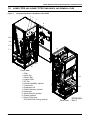
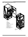
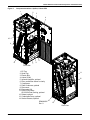
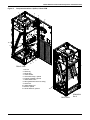
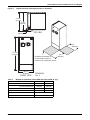
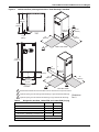
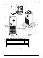
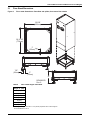
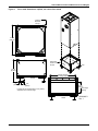
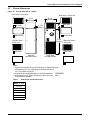
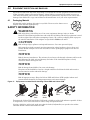
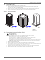
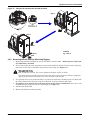
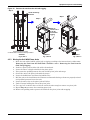
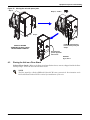
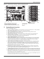
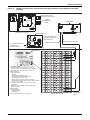
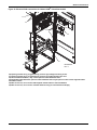
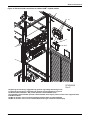
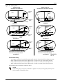

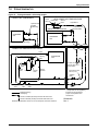
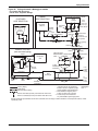
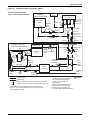
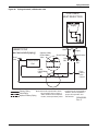
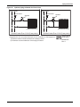
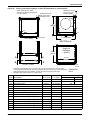

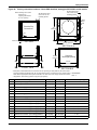
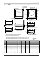
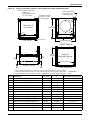
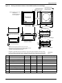
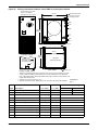
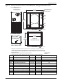
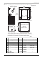
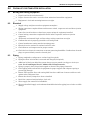
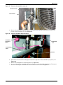
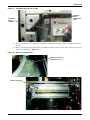
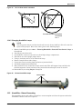
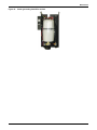
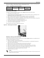
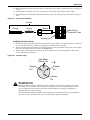
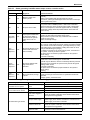
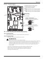


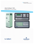
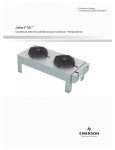
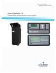
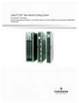


![ORIGEM : [Clique aqui e digite a origem]](http://vs1.manualzilla.com/store/data/006088704_1-fdfc612ddaac7c562571bd6440a29c4b-150x150.png)