1
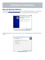
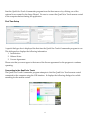
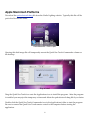
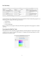
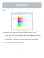
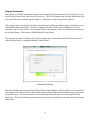
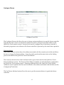
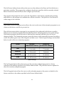
QualColor™ Touch
Commander
Installation and User Manual
Introduction
The QualColor Touch Commander program is designed to provide additional capabilities with the
Model RC-001 QualColor Touch remote control.
The primary use of the QualColor Touch Commander is to configure advanced attributes of the
RC-001 including the following.
1. Radio Channel and/or Network Id.
2. Fade Time and presets associated with the M1 and M2 buttons.
3. Program associated with the Auto button.
4. Linked Fixture and Fixture Address.
It provides some additional capabilities including the following.
1. Computer control of one or more fixtures including thematic-based automatic programs.
2. The ability to set a specific Fixture Address and power-on program.
Important Information
Please read through the remaining instructions before installing and using this software.
This software has been designed and tested to operate on the following platforms. Its operation on
other platform configurations cannot be assured.
1. Microsoft Windows Platforms: Windows XP with SP2, Windows Vista, Window 7
• 25 MB spare disk space
• Spare USB Port
2. Apple Macintosh Platforms: Mac OS X 10.5 or later running on an Intel Processor
• 25 MB spare disk space
• Spare USB Port
This manual assumes you have read the User Manual for the QualColor Touch remote control (Model
RC-001) and the Giulio Lighting controller linked to it. Do not connect the QualColor Touch remote
control to the computer before installing the application. Connecting the RC-001 to the computer
before the software has been installed may cause the operating system to prompt for an installation
disk. Click the Cancel button if this happens. All necessary software will be installed along with the
program.
1
Revision Information
Version 1.1
• Added support for multiple fixtures to the Color Dimmer and Effects tabs. The feature is
enabled through a new properties (Microsoft Windows) or preferences (Mac OS X) menu
item. These tabs can now control up to 10 individually addressed fixtures.
• Added the capability in the Configure QCTouch tab to enable fixture power-fail recovery in
the RC001. This feature is only enabled with a specific key sequence. Contact Giulio
Lighting if use of this feature is necessary.
• Added the capability in the Configure Fixture tab to configure to default power-on
program in a light fixture controller.
• Revamped the help system.
Version 1.0
• Initial release.
2
Software Installation
Microsoft Windows Platforms
Download the QualColorTouchSetup.exe.zip file from the Giulio Lighting website. You may choose
to store it somewhere or open it upon download. Unzip the file and start the Setup Wizard.
QualColor Touch Commander Setup Wizard
The Setup Wizard allows you to create a shortcut icon on the desktop and/or a Quick Launch icon if
desired.
Selecting additional icons
3
Start the QualColor Touch Commander program from the Start menu or by clicking one of the
optional icons created by the Setup Wizard. Be sure to connect the QualColor Touch remote control
to the computer before starting the application.
First Time Setup
A special dialogue box is displayed the first time the QualColor Touch Commander program is run.
This dialogue box displays the following information.
1. Introduction
2. Release Notes
3. License Agreement
Please note that you must agree to the terms of the license agreement for the program to continue
operating.
Connecting to the QualColor Touch
The QualColor Touch Commander program attempts to find the QualColor Touch remote control
connected to the computer using the USB interface. It displays the following dialogue box while
searching for the remote control.
4
Apple Macintosh Platforms
Download the qualcolortouch.dmg file from the Giulio Lighting website. Typically this file will be
put in the Downloads folder.
Downloaded file. Click to open.
Opening this disk image file will temporarily mount the QualColor Touch Commander volume on
the desktop.
Drag to install.
Drag the QualColor Touch icon onto the Applications icon to install the program. After the program
is installed you may eject the temporary volume and delete the qualcolortouch.dmg file if you desire.
Double-click the QualColor Touch Commander icon in the Applications folder to start the program.
Be sure to connect the QualColor Touch remote control to the computer before starting the
application.
5
First Time Setup
A special dialogue box is displayed the first time the QualColor Touch Commander program is run.
This dialogue box displays the following information.
1. Introduction
2. Release Notes
3. License Agreement
Please note that you must agree to the terms of the license agreement for the program to continue
operating.
Connecting to the QualColor Touch
The QualColor Touch Commander program attempts to find the QualColor Touch remote control
connected to the computer using the USB interface. It displays the following dialogue box while
searching for the remote control.
6
Operation
A simple control panel is displayed once the program has started and successfully found a remote
control.
QualColor Touch Commander
The control panel displays individual tabs for the four functions the program provides.
1. Color Dimmer : Manually control the selected fixture(s) from the computer screen.
2. Dynamic Effects : Let the computer dynamically change the selected fixture(s) according to a
user-selected theme.
3. Configure QCTouch : Configure various attributes in the QualColor Touch remote control.
4. Configure Fixture : Set the address or power-on program in a specific fixture controller.
Click on a tab to move between the four main functions.
7
Program Preferences
The QualColor Touch Commander program sets the default Fixture address (Zone and Unit) in each
tab to the the current link value when it is first run. The Color Dimmer and Dynamic Effects tabs will
only control fixtures with that specific address. This mode is called Single Fixture Mode.
The program may be configured for the Color Dimmer and Dynamic Effects tabs to operate up to ten
sequentially addressed fixtures. The Color Dimmer tab may be used to set a different color and
intensity value for each fixture. The Dynamic Effects tab generates colors for all fixtures according to
the selected theme. This mode is called Multiple Fixture Mode.
The Preferences menu item (Mac OS X) and Properties menu item (Microsoft Windows) are used to
select the mode and to configure Multiple Fixture Mode.
Preferences/Properties
The Zone Address and Starting Unit Address fields set the address of the first fixture to be controlled.
The Number of Fixtures field sets the number of sequentially addressed fixtures starting with the first
addressed fixture. All fixtures must be set with the same Zone address and with sequential Unit
addresses. The Zone and Starting Unit addresses are shown on both the Color Dimmer and Dynamic
Effects tabs.
8
Color Dimmer
Color Dimmer Tab in Single Fixture Mode
Color Dimmer Tab in Multiple Fixture Mode
The Color Dimmer tab allows the user to interactively change the color and/or intensity of selected
light fixture(s). The QualColor Touch must be within range of the light fixture.
9
Fixture Address
The Zone and Unit fields set the fixture address of the light fixture controller. The way the Fixture
Address is set and used depends on the current mode. Single Fixture Mode is used when the
QualColor Touch remote control is linked to a single fixture controller (or multiple fixture controllers
sharing the same address). Multiple Fixture Mode allows the QualColor Touch remote control to
operate up to ten fixture controllers, each with a unique address.
Single Fixture Mode
The Zone and Unit fields may be changed to address any fixture. These fields are set initially to
match the currently active link in the QualColor Touch. Either type a new value in the field or use the
up/down arrow keys to change the value.
Multiple Fixture Mode
The Zone and Unit fields indicate the base fixture address (unit address of the first fixture). The
Selected Fixture buttons allows the user to select the specific fixture unit address to control (or all
fixtures simultaneously). The zone address, base unit address and number of fixtures are set using
the preferences (properties) menu item.
Color Selector
The Color selector graphic allows the user to set the hue and saturation of the fixture. Click the
mouse over the desired hue and saturation to select a new value or drag the mouse in the graphic to
change the value dynamically. The arrow keys may also be used for precise changes.
Intensity Slider
The Intensity slider allows the user to set the brightness of the fixture. Click the mouse along the
slider to set a new intensity level or use the mouse to grab the control and then drag the mouse up
and down to dynamically change the brightness.
The QualColor Touch Commander program attempts to get and display the current color dimmer
settings from the fixture when the program first starts running and anytime the Selected Fixture is
changed in Multiple Fixture mode.
10
Dynamic Effects
Dynamic Effects Tab
The Dynamic Effects tab allows the user to run an automatic program on the computer that will
dynamically change the color of a light fixture according to the selected theme. The QualColor Touch
must be within range of the light fixture.
Fixture Address
The Zone and Unit fields set the fixture address of the light fixture controller. The way the Fixture
Address is set and used depends on the current mode. Single Fixture Mode is used when the
QualColor Touch remote control is linked to a single fixture controller (or multiple fixture controllers
sharing the same address). Multiple Fixture Mode allows the QualColor Touch remote control to
operate up to ten fixture controllers, each with a unique address.
Single Fixture Mode
The Zone and Unit fields may be changed to address any fixture. These fields are set initially to
match the currently active link in the QualColor Touch. Either type a new value in the field or use the
up/down arrow keys to change the value.
11
Multiple Fixture Mode
The Zone and Unit fields indicate the base fixture address (unit address of the first fixture). These
fields are set using the preferences (properties) menu item. The QualColor Touch Commander
program will control all units configured using the preferences (properties) menu item.
Effect
The Effect buttons allows the user to select the desired theme. Click the button next to the theme
name to start an automatic effect program. Click the "Off" button to turn off the program. Effects will
also be turned off when a different tab is selected. All light fixtures configured using the preferences
(properties) menu will be controlled according to the selected theme.
Speed
The Speed slider allows the user to set the rate at which the colors transition from one value to the
next. Click the mouse along the slider to set a new rate or use the mouse to grab the control and then
drag the mouse up and down to dynamically change the rate. Note that the computer waits for the
current color transition to complete before picking a new one. This may result in a long delay when
changing speed.
12
Configure QCTouch
Configure QCTouch Tab
The Configure QCTouch tab allows the user to change various operating attributes of the QualColor
Touch remote control. The tab is organized into three areas.
1. Radio Interface
2. Function Buttons
3. Fixture Addresses
When the program is first run the current values in the QualColor Touch remote control are displayed
in these three areas. A red check mark is displayed next to any item that has been changed. The
check mark is an indicator that the value does not match the value in the remote control.
The Set QCTouch button loads any values that have been changed into the remote control. The
Default button sets all values to the factory default values.
13
Radio Interface
The Radio Interface section allows the user to select a different radio channel or Network Id to avoid
interference with other devices or systems.
The four radio channels are spread across the frequency spectrum that the LEDlink radio protocol
operates in. Channel 1 is at the low-end of the spectrum. Channel 4 is at the high-end of the
spectrum. Channels 2 and 3 are approximately one-third and two-thirds of the way through the
spectrum but adjusted slightly to avoid the most common computer WiFi frequencies.
The factory default is channel 1. It is recommended to try channel 4 next and then channels 2 and 3 if
radio interference is suspected. Click the radio button next to the desired radio channel and then
click the Set QCTouch button to update the value in the remote control.
The Network Id is a linking attribute that can be used to separate different LEDlink networks even if
they overlap physically. The typical use is to avoid interference with a system residing outside of the
user’s control, for example in another apartment or home. If fixtures in both locations change
whenever either remote control is used then it is appropriate to change the Network Id in one
location.
The factory default Network Id is 0. The Network Id may have any value 0 - 255. Two LEDlink
networks with different Network Ids will not interfere with each other even if they are operating on
the same radio channel and have fixtures with the same addresses.
To eliminate interference between different LEDlink networks change the Network Id value and then
click the Set QCTouch button to update the value in the remote control.
Note that for any changes in the radio channel or Network Id the QualColor Touch will need to be
re-linked with the fixture controllers it is operating so that these controllers may be updated to use
the new link information. The linking process is described in the QualColor Touch User Manual.
14
Function Buttons
The Function Buttons section allows the user to change the values assigned to the M1, M2 and Auto
buttons.
The square next to the M1 and M2 labels indicates the current memory preset value associated with
each button. Clicking on the square brings up a color selector that allows the user to change the hue,
saturation and intensity associated with each button.
The Fade Time field allows the user to change how long the transition to a color selected by the M1 or
M2 buttons take. The factory default value for this setting is one second. The user may change this
value to any value from 0 - 25 seconds.
The Auto pull-down menu allows the user to change the automatic program assigned to the Auto
button. There are two automatic programs, Random and Sequential. Each program has four speed
settings. The Random program causes the fixture to fade between randomly selected colors for an
ever changing display. The Sequential program causes the fixture to fade repeatedly between the
rainbow colors: red, yellow, green, cyan, blue, magenta and back to red. The four speed settings are
described below for each of the two automatic programs.
Speed
Random
Sequential
(fade between colors) (for full color change)
Fast
1 - 6 seconds
15 seconds
Med/Fast
5 - 30 seconds
3 minutes
Med/Slow
10 - 60 seconds
10 minutes
Slow
30 - 180 seconds
30 minutes
Speed Settings
Clicking the Set QCTouch button will load new Function Button values into the remote control. It is
not necessary to re-link the remote control with any fixture controllers for changes to the Function
Buttons to take effect.
15
Fixture Addresses
As described in the QualColor Touch User Manual, each RC-001 remote control contains a built-in
mechanism for quickly changing the link to support up to 3 separately addressed fixtures.
The Fixture Addresses area shows the current active link and the fixture address associated with the
link. Typically this area is used for advanced modifications including linking a fourth or higher
remote control and fixture or changing the fixture address associated with a particular link.
The Active link used by the QualColor Touch remote control may be changed by selecting one of the
three Active radio buttons.
The address that the QualColor Touch remote control will use for each link may also be changed in
the Zone and Unit fields above the link identifier. Zone addresses range from 1 - 65535 (Zone
addresses 65531-65535 are reserved and should not be used). Unit address may range from 1 - 65535.
Click on the Set QCTouch button to load new Fixture Address information into the QualColor Touch
remote control.
Note that the fixture controller must also be configured with the same address as the active link in
the QualColor Touch remote control. This may be done in one of two ways. The first method
utilizes the built-in linking capability of the remote control and is described in the User Manual. It is
useful if the controller is already installed and is far from the computer running the QualColor Touch
Commander program. The second method utilizes the fourth tab, Configure Fixture, described in
the next section.
16
Configure Fixture
Configure Fixture Tab
The Configure Fixture tab allows the user to change various attributes in a specific fixture controller.
Typically this tab is used to set the fixture address to match a changed active link address in the
QualColor Touch remote control. It may also be used to configure one of the fixture controller’s
automatic programs to run whenever the fixture controller is powered up for stand-alone operation.
Fixture Address
The Fixture Address section shows the address associated with the currently active link and allows
the user to change the fixture address. It may be used to perform the same action as the linking
process described in the QualColor Touch User Manual.
The currently selected active link is indicated with a green check mark in the QualColor Touch
Fixture Addresses section. The Zone and Unit fields are initially set with the address configured in
the QualColor Touch remote control. Selecting a different link in the QualColor Touch Fixture
Addresses section updates the Zone and Unit fields to the address associated with that link (see the
Configure QCTouch tab).
The Get Fixture Address button allows the user to get the current address of a particular fixture
controller.
17
The Set Fixture Address button allows the user to set the address in the Zone and Unit fields into a
particular controller. The program also configures the fixture controller with the currently selected
Radio Channel and Network Id (see the Configure QCTouch tab).
The program will prompt the user to press the Prog Button on the fixture controller after pressing
either button so the program can communicate with the controller. The QualColor Touch must be
within range of the controller.
Fixture Power-On Program
The Fixture Power-On Program section allows the user to select one of the automatic programs to run
whenever the fixture controller is powered on.
The pull-down menu selects a program (or no program) to be configured in the fixture controller.
There are two automatic programs, Random and Sequential. Each program has four speed settings.
The Random program causes the fixture to fade between randomly selected colors for an ever
changing display. The Sequential program causes the fixture to fade repeatedly between the rainbow
colors: red, yellow, green, cyan, blue, magenta and back to red. The four speed settings are described
below for each of the two automatic programs.
Speed
Random
Sequential
(fade between colors) (for full color change)
Fast
1 - 6 seconds
15 seconds
Med/Fast
5 - 30 seconds
3 minutes
Med/Slow
10 - 60 seconds
10 minutes
Slow
30 - 180 seconds
30 minutes
Speed Settings
The Get Program button allows the user to get the currently configured program in a fixture
controller at the address specified in the Fixture Address fields. The pull-down menu is updated to
show the currently configured program.
The Set Program button allows the user to set the selected program as the power-on default in the
fixture controller at the address specified in the Fixture Address fields.
18
The program will prompt the user to press the Prog Button on the fixture controller after pressing
either button so the program can communicate with the controller. The QualColor Touch must be
within range of the controller.
Note that the fixture controller will respond to commands from the QualColor Touch remote
control if a Power-On program is running. The command from the remote control will take
precedence over the running program.
19
Examples
Changing Radio Interface values
Assume that there is radio interference from a Microwave oven that prevents proper operation of the
QualColor Touch remote control and fixture it controls. The QualColor Touch remote control is in the
factory default condition operating on Radio Interface Channel 1 with active link 1.
Microwave ovens generally do not emit radio interference across the entire frequency spectrum that
the LEDlink interface can utilize. Changing to Radio Interface Channel 4 should alleviate the
interference.
The following procedure may be followed to change the Radio Interface Channel in the QualColor
Touch remote control and the fixture it controls.
1. Connect the QualColor Touch remote to the computer and start the QualColor Touch
Commander program.
2. Select the Configure QCTouch tab. Select Radio Channel 4 and load this into the remote
control by pressing the Set QCTouch button.
3. Exit the QualColor Touch Commander program and disconnect the remote control from the
computer (always disconnect the remote control after quitting the program).
4. Take the QualColor Touch remote control to the fixture. Put the fixture controller into
provisioning mode by pressing the Prog button and observing that the Prog indicator is
illuminated.
5. Put the QualColor Touch remote control into linking mode by pressing the Link Mode button
with the unrolled end of a paperclip. The red indicator will blink slowly. Press the “M1”
button briefly to re-link the remote control to the fixture controller. Observe the Prog indicator
on the fixture controller is turned off indicating a successful link.
6. Press the Link Mode button again on the remote control or wait until the red indicator stops
blinking (approximately 30 seconds) and test operation of the system operating at the new
radio channel.
See the QualColor Touch remote control User Manual for more information on the linking process.
If this is the second or third pair of remote controls and controllers use the “M2” or “AUTO” button
as necessary during the linking step (step 5 above).
20
Advanced Linking Example
Assume there are already three separately operating pairs of QualColor Touch remote controls and
fixture controllers and it is desired to add a fourth. The first three pairs use the default fixture
address values.
1. Pair 1 : Zone = 1, Unit = 1, Active Link = 1
2. Pair 2 : Zone = 1, Unit = 2, Active Link = 2
3. Pair 3 : Zone = 1, Unit = 3, Active Link = 3
The fourth pair will be configured to use a fixture address Zone = 1 and Unit = 4 with the following
procedure.
1. Connect the QualColor Touch remote to the computer and start the QualColor Touch
Commander program.
2. Select the Configure QCTouch tab. Set the Fixture Address for Active Link 1 is set to Zone = 1
and Unit = 4 (make sure the Active radio button by “1” is selected). Load this into the
QualColor Touch remote control by pressing the Set QCTouch button.
3. Exit the QualColor Touch Commander program and disconnect the remote control from the
computer (always disconnect the remote control after quitting the program).
4. Take the QualColor Touch remote control to the fixture. Put the fixture controller into
provisioning mode by pressing the Prog button and observing that the Prog indicator is
illuminated.
5. Put the QualColor Touch remote control into linking mode by pressing the Link Mode button
with the unrolled end of a paperclip. The red indicator will blink slowly. Press the “M1”
button briefly to re-link the remote control to the fixture controller. Observe the Prog indicator
on the fixture controller is turned off indicating a successful link.
6. Press the Link Mode button again on the remote control or wait until the red indicator stops
blinking (approximately 30 seconds) and test operation of the system operating at the new
Fixture Address pair.
See the QualColor Touch remote control User Manual for more information on the linking process.
21
Troubleshooting
QualColor Touch Commander Error Messages
Error Message
No interface device detected!
Found a device but could not
connect to it.
Could not communicate with
the remote device.
Possible Cause
Action
The QualColor Touch remote
control is not connected to the
computer.
Make sure the remote control is
connected to a spare USB port
on the computer and that the
power indicator on the remote
control is lit.
Software is not properly
installed.
Re-install the software package.
Software is not properly
installed.
Re-install the software package.
A USB Hub between the
computer and the interface
device is not compatible with
the QualColor Touch remote
control.
Connect the remote control
directly to a USB port on the
computer running QualColor
Touch Commander.
The Giulio Lighting controller
is too far away from the
QualColor Touch remote
control for reliable radio
communication.
Move the controller closer to
the remote control, ideally
within 5 feet / 2 m.
There was interference during
the LEDlink radio
communication between the
QualColor Touch and fixture
controller.
Attempt the operation again. If
it continues to fail you may
want to change the radio
channel.
22
Error Message
The fixture address was not
successfully provisioned.
Could not verify the fixture
address was successfully
provisioned.
Possible Cause
Action
The QualColor Touch remote
control and fixture controller
are not properly linked
together.
Use the linking procedure
described in the remote
control’s User Manual to link it
with the controller.
The Giulio Lighting controller
was not in provisioning mode.
Attempt to provision the
controller again. Make sure the
controller is in provisioning
mode by pressing the Prog
button and verifying the Prog
indicator is lit.
The controller is too far away
from the QualColor Touch
remote control for reliable
radio communication.
Move the controller closer to
the remote control, ideally
within 5 feet / 2 m.
There was interference during
the LEDlink radio
communication between the
QualColor Touch remote
control and controller.
Attempt to provision the
controller again. If it continues
to fail you may want to change
the radio channel.
The Giulio Lighting controller
is too far away from the
QualColor Touch remote
control for reliable radio
communication.
Move the controller closer to
the remote control, ideally
within 5 feet / 2 m.
There was interference during
the LEDlink radio
communication between the
QualColor Touch and
controller.
Attempt to provision the
controller again. If it continues
to fail you may want to change
the radio channel.
23
Error Message
Could not get the fixture
address.
Possible Cause
Action
The Giulio Lighting controller
was not in provisioning mode.
Try again but make sure the
controller is in provisioning
mode by pressing the Prog
button and verifying the Prog
indicator is lit.
The controller is too far away
from the QualColor Touch
remote control for reliable
radio communication.
Move the controller closer to
the remote control, ideally
within 5 feet / 2 m.
24
Copyright © 2010 Giulio Lighting
All rights reserved
QualColor is a trademark of Giulio Lighting.
Windows is a registered trademark of
Microsoft in the United States and other
countries. Macintosh is a trademark of Apple
Inc. All other brand or product names are
trademarks or registered trademarks of their
respective owners.
Contact
www.giuliolighting.com
[email protected]
This document and the functionality of the
product may be subject to change without
notice.
Publication 24-00026-01