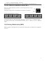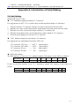
1
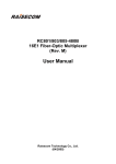
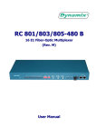
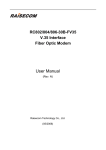
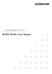
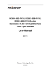
RC802-30B, RC802-30B-BL RC804-30B, RC804-30B-BL RC806-30B, RC806-30B-BL Single E1 link Modular Optical Multiplexer User Manual (Rev. M) Beijing Raisecom Science & Technology Co., Ltd. CONTENT CHAPTER 1. INTRODUCTION ..................................................................................1 1.1 MAIN FEATURES .........................................................................................................................1 1.2 PRODUCT ARTICLE DESCRIPTION ................................................................................................1 CHAPTER 2. PRODUCT SPECIFICATIONS ....................................................3 2.1 E1 INTERFACE SPECIFICATION ....................................................................................................3 2.2 OPTICAL FIBER INTERFACE SPECIFICATION ................................................................................3 2.3 POWER SUPPLY ...........................................................................................................................3 2.4 AMBIENCE ...................................................................................................................................3 CHAPTER 3. DEFINITION OF INDICATORS ................................................4 3.1 DESCRIPTION OF THE FRONT PANEL ............................................................................................4 3.1.1 Power Supply Indicator ......................................................................................................4 3.1.2 Alarm Indicators .................................................................................................................4 3.1.3 E1 Interface.........................................................................................................................5 3.1.4 Optical Interface .................................................................................................................5 3.2 DIP-SWITCH SETUP ......................................................................................................................5 3.2.1 Dip-switch SW2 Setup.........................................................................................................5 3.2.2 E1 Interface Impedance Setup (SW1) .................................................................................7 3.2.3 Manufactory setup (SW3)....................................................................................................7 CHAPTER 4. INSTALLATION AND TEST ........................................................8 4.1 INSPECTING THE PRODUCT ..........................................................................................................8 4.2 PREPARATION BEFORE INSTALLATION ........................................................................................8 4.3 INSTALLATION.............................................................................................................................8 4.3.1 Connecting Data Interfaces ................................................................................................8 4.3.2 Applying Power Supply.......................................................................................................8 4.3.3 Configuration with Buttons and Dip-switches ....................................................................9 CHAPTER 5. TROUBLESHOOTING ....................................................................10 APPENDIX A. INTRODUCTION OF CABLE MAKING.........................11 Raisecom RC802/804/806-30B(-BL) User Manual Beijing Raisecom Science & Technology Co.,Ltd Tel:86-10-82884499 http://www.raisecom.com Chapter 1. Introduction RC800-30B series optical modular multiplexers are ideal equipments to transmit single-channel E1 signals over optical fiber. It can be inserted into Raisecom’s chassis which can also accommodate other Raisecom series products to enable uniform network management. RC800-30B series are compact in size and highly integrated with versatile capabilities. RC800-30B also can be inserted into Raisecom’s single slot chassis to be flexibly deployed at the remote site. The RC800-30B series optical multiplexers are ideal for point-to-point, medium-sized and small capacity networks, such as wireless communication base stations, dedicated communication networks and switching networks. The transmission capacity of RC800-30B series is single channel E1 (equivalent to 30 voice channels). 1.1 Main Features z z z z RC800-30B series optical multiplexers adopt extra large-scale ASIC chips with low power consumption. Four-level PCB circuit board ensures high reliability. RC800-30B provides complete alarm indications. The local and remote alarms can be displayed simultaneously. RC800-30B supports loop-back function for E1 channel. It is convenient for deployment, operation and maintenance. RC800-30B is also featured by modularization design with high security, stability, reliability, and easy to use. Power supply is provided from the chassis backplane. 1.2 Product Article Description Article RC802-30B-S1 RC802-30B-BL-S1 RC802-30B-S2 RC802-30B-BL-S2 RC802-30B-S3 RC802-30B-BL-S3 RC804-30B-S1 RC804-30B-BL-S1 Description Module at central office/customer premise, two CC3 interfaces (75Ω, unbalanced), one optical port, dual-fiber single mode (DSC), 0-25Km Module at central office/customer premise, one RJ45 interface (120Ω, balanced), one optical port, dual-fiber single mode(DSC), 0-25Km Module at central office/customer premise, two CC3 interfaces (75Ω, unbalanced), one optical port, dual-fiber single mode(DSC), 10-60Km Module at central office/customer premise, one RJ45 interface (120Ω, balanced), one optical port, dual-fiber single mode(DSC), 10-60Km Module at central office/customer premise, two CC3 interfaces (75Ω, unbalanced), one optical port, dual-fiber single mode(DSC), 15-120Km Module at central office/customer premise, one RJ45 interface (120Ω, balanced), one optical port, dual-fiber single mode(DSC), 15-120Km Central office module, two CC3 interfaces (75Ω, unbalanced), one optical port, single fiber single mode 1310 (SC-PC), dual-wavelength, 0-25Km Central office module, one RJ45 interface (120Ω, balanced), one optical port, single fiber single mode 1310(SC-PC), dual-wavelength, 0-25Km -1- Raisecom RC802/804/806-30B(-BL) User Manual Beijing Raisecom Science & Technology Co.,Ltd Tel:86-10-82884499 http://www.raisecom.com Central office module, two CC3 interface(75Ω, unbalanced), one optical port, single fiber single mode 1310(SC-APC), dual-wavelength, 10-60Km Central office module, one RJ45 interface (120Ω, balanced), one optical port, single RC804-30B-BL-S2 fiber single mode 1310 (SC-APC), dual-wavelength, 10-60Km RC806-30B-S1 Customer premises module, two CC3 interfaces (75Ω, unbalanced), one optical port, single fiber single mode 1550 (SC-PC), dual-wavelength, 0-25Km RC806-30B-BL-S1 Customer premises module, one RJ45 interface (120Ω, balanced), one optical port, single fiber single mode 1550 (SC-PC), dual-wavelength, 0-25Km RC806-30B-S2 Customer premises module, two CC3 interfaces (75Ω, unbalanced), one optical port, single fiber single mode 1550 (SC-APC), dual-wavelength, 10-60Km RC806-30B-BL-S2 Customer premises module, one RJ45 interface (120Ω, balanced), one optical port, single fiber single mode 1550 (SC-APC), dual-wavelength, 10-60Km RC804-30B-S2 The following products can work in pairs: Central office module RC802-30B(-BL)-S1 RC802-30B(-BL)-S2 RC802-30B(-BL)-S3 RC804-30B(-BL)-S1 RC804-30B(-BL)-S2 Customer premises module RC802-30B(-BL)-S1 RC801-30B-FV35-S1 RC802-30B(-BL)-S2 RC801-30B-FV35-S2 RC802-30B(-BL)-S3 RC801-30B-FV35-S3 RC806-30B(-BL)-S1 RC805-30B-FV35-S1 RC806-30B(-BL)-S2 RC805-30B-FV35-S2 -2- Raisecom RC802/804/806-30B(-BL) User Manual Beijing Raisecom Science & Technology Co.,Ltd Tel:86-10-82884499 http://www.raisecom.com Chapter 2. Product Specifications 2.1 E1 Interface Specification Bit rate: Line code: Impedance of interface: Electrical characteristics: Transfer characteristics: Input jitter tolerance: 2048Kbps±50ppm HDB3 75Ω (unbalanced) or 120Ω (balanced) complies with ITU-T G.703 complies with ITU-T G.823, G.724 complies with ITU-T G.823, G.724 2.2 Optical Fiber Interface Specification Bit rate: 100Mbps Line code: 4B5B Fiber connecter: SC (FC available for some types) Optical Transmission of single strand fiber: Transmit power: ≥-15 dBm Receiving sensitivity: ≤-31 dBm Transmit Wavelength: 1310/1550nm Distance: >25km Optical Transmission of dual-strand fiber: Transmit power: ≥-5 dBm Receiving sensitivity: ≤-35 dBm Transmit Wavelength: 1310nm Distance: >40km 2.3 Power Supply Power supply: Power consumption: DC –48 AC 220V tolerance range –36V ~ -72V tolerance range 165V~265V ≤5W 2.4 Ambience Working temperature: 0 ~ 45℃ Humidity: ≤90% (25℃ non-condensing) -3- Raisecom RC802/804/806-30B(-BL) User Manual Beijing Raisecom Science & Technology Co.,Ltd Tel:86-10-82884499 http://www.raisecom.com Chapter 3. Definition of Indicators 3.1 Description of the Front Panel Optical Link Optical Link Bit E1 Loss Alarm Loss Alarm Error Alarm Power Fiber Port E1 Port Indicator L/R LOS TX RX PWR LERR RERR LLOS OUT IN RLOS Figure 1. The front panel of RC802/804/806-30B module Optical Link Optical Link E1 Loss Alarm Bit Error Alarm Loss Alarm Power Fiber Port E1 Port Indicator L/R LOS TX PWR RX LERR RERR LLOS E1 RLOS Figure 2. The front panel of RC802/804/806-30B-BL module 3.1.1 Power Supply Indicator PWR power supply indicator (green): Steady on, built-in power works in good condition. 3.1.2 Alarm Indicators z z Loss of signal in E1 channel: LLOS local signal loss alarm in E1 channel (red): ON when the receiving signal loss occurs at the local site. RLOS remote signal loss alarm in E1 channel (red): ON when the receiving signal loss occurs at the remote site. Alarm of optical port: L/R LOS receiving signal loss alarm in optical link (red): ON when the receiving signal loss occurs at the local site; Flashing, when the receiving signal loss occurs at the remote site. -4- Raisecom RC802/804/806-30B(-BL) User Manual Beijing Raisecom Science & Technology Co.,Ltd Tel:86-10-82884499 http://www.raisecom.com LERR receiving signal error alarm in optical link (yellow): ON when LOF (loss of frame alignment) occurs or the receiving BER exceeds 10-3 level at local site. RERR receiving signal error alarm in optical link (yellow): ON when LOF (loss of frame alignment) occurs or the receiving BER exceeds 10-3 level at remote site. 3.1.3 E1 Interface RC802/804/806-30B series modules provide two CC3 connectors for single E1 channel interface; RC802/804/806-30B-BL series modules provide one RJ45 interface. Please refer to Appendix A for connection details. z z The factory default setup for CC3 connector is 75Ω unbalanced signal transmission. OUT is signal output; IN is signal input. The factory default setup for RJ45 interface is 120Ω balanced signal transmission. Pin 1, 2 are signal output; Pin 5, 6 are signal input. 3.1.4 Optical Interface z z For dual-strand fiber, the optical connector is DSC/PC. TX means transmitting, RX means receiving. For single strand fiber, the optical connector is SC/PC. 3.2 Dip-switch Setup 3.2.1 Dip-switch SW2 Setup Please use small flat-blade screwdriver or other sharp end tools to set up the dip-switch. z 1st bit: E1 link loop-back setup 1st Loop-back setup OFF No loop-back ON Bi-directional loop-back The factory default setup is ‘OFF’. z ON OFF 1234 2nd: E1 link loop-back location setup 2nd Loop-back setup OFF Remote loop-back ON Local loop-back The factory default setup is ‘OFF’. Note that the 2nd bit is only effective when the 1st bit is switched to ON. -5- Raisecom RC802/804/806-30B(-BL) User Manual Beijing Raisecom Science & Technology Co.,Ltd Tel:86-10-82884499 BER Tester E1 Local Optical Multiplexer Fiber http://www.raisecom.com BER Tester Remote Optical Multiplexer If “local loop-back” is set up on local optical multiplexer, the local optical multiplexer will generate internal-loop and external-loop simultaneously. BER Tester E1 Local Optical Multiplexer Fiber Remote Optical E1 BER Tester Multiplexer If “remote loop-back” is set up on local optical multiplexer, the remote optical multiplexer will generate internal-loop and external-loop simultaneously. z 3rd bit: Fault-Pass-Through (FPT) function setup When FPT is disabled, it is identical to the AIS function of traditional optical multiplexers. When the receiving signals of the E1 interface at the remote site are lost, the CORRESPONDING local E1 interface will output all “1” signals; when the receiving signals of the local optical interface are lost, ALL local E1 interfaces will output all “1” signals. FPT is designed for users who have special requirements. When FPT is enabled, if there is alarm of LOS on any direction of optical interface,E1 interfaces on both sides will not output HDB3 code. In this case, there will be LOS alarm, rather than AIS alarm, on downstream E1 terminal devices (e.g. Switches, converters or SDH devices). 3rd bit OFF ON z FPT switch Disable (identical to the AIS function of traditional optical multiplexers) Enable The factory default setup is OFF 4th bit: Setup for forced monitor and management by the remote optical multiplexer When optical multiplexers are working in pairs, if the module is plugged into RC001-1 single slot chassis deployed at customer premise, the module will be automatically set up to be managed by the host-site multiplexer; if it is plugged into RC002-16 16-slot chassis, to be managed by the remote multiplexer, the module need to be manually set up to that working mode. 4th bit OFF ON Remote management setup Auto-sensing management setup Forced management by the remote-site multiplexer -6- Raisecom RC802/804/806-30B(-BL) User Manual Beijing Raisecom Science & Technology Co.,Ltd Tel:86-10-82884499 http://www.raisecom.com 3.2.2 E1 Interface Impedance Setup (SW1) Please use a small flat-blade screwdriver or other sharp end tools to set up the dip-switch. Each group of dip-switch is corresponding to its respective E1 interface. ON OFF The dip-switch definition is as follows: 1st 2nd 3rd 4th ON ON ON OFF Effective for 75Ω unbalanced signals or 1234 1st 2nd 3rd 4th OFF OFF OFF ON Effective for 120Ω balanced signal The factory default setup of RC802/804/806-30B series is “Effective for 75Ω unbalanced signal”. The factory default setup of RC802/804/806-30B-BL series is “Effective for 120Ω balanced signal”. 3.2.3 Factory Default setup (SW3) SW3 is a group of 2-bit dip-switch. It is set up by the factory and is not allowed to be changed by end-users. -7- Raisecom RC802/804/806-30B(-BL) User Manual Beijing Raisecom Science & Technology Co.,Ltd Tel:86-10-82884499 http://www.raisecom.com Chapter 4. Installation and Test 4.1 Inspecting the Product Before installation, please first check the models and quantities of optical multiplexers and accessories with the packing list. Also, please check whether the equipment is in perfect condition. Occasionally, drying process may be needed if the equipment is affected with damp environment. 4.2 Preparation Before Installation The following steps are required before installing the optical multiplexers: Please read the user manual carefully. Prepare all the wires and cables that are needed. Make sure there is no reverse connection, disconnection or short circuit connection. Refer to Appendix A for details of cable making. Make sure that the voltage of the power supply is within the tolerance range and the chassis is grounded with the earth. Prepare the bit-error-rate tester and optical power test-meter for the test of link quality. If using 120Ω balanced signal interface, please change the dip-switch setup on the bottom of the optical multiplexer. Fix the optical multiplexer into RC001-16 (19-inch 3U chassis). Pay attention to the ambience requirement. 4.3 Installation 4.3.1 Connecting Data Interfaces z E1 interface It is suggested to use SYV 75-2-2 coaxial cable for CC3 connector, and use twisted pairs for RJ45 connector. z Optical interface Insert the SC fiber tail into the optical interface (push hard until to the end). If you are not sure about transmission direction, it’s advised to connect the fiber cable after applying the power supply. 4.3.2 Applying Power Supply Insert the module into the chassis and fix it with the screw at the bottom of the module. If the power supply is DC –48V, please ground the PGND with the earth first, then “-48V” pin with the lower voltage cable, “0V” pin with higher voltage cable before applying the power supply. Make sure it is firmly fixed, and there’s no reverse connection and no short circuit before applying -8- Raisecom RC802/804/806-30B(-BL) User Manual Beijing Raisecom Science & Technology Co.,Ltd Tel:86-10-82884499 http://www.raisecom.com the power supply. If the power supply is AC 220V, please use the power cable in the accessories provided by the factory. After applying the power supply, the PWR indicator shall be steadily ON. 4.3.3 Configuration with Buttons and Dip-switches After applying the power supply of the optical multiplexers, first ensure there’s no alarm at optical ports. If optical ports are connected properly, there shall be no LOS, LOF or ERR alarm. The ERR (yellow) may be ON within a short period after the power supply is just applied. This is because applying the power supply will cause jitters, and result in a few bit errors. After 10 seconds, ERR will be off and this indicator refreshes test every 10 seconds. z Testing bit error rate The bit error rate can be tested by 2M bit-error-rate tester, and the testing can be implemented by setting up loop-back control switch (the 1st and 2nd bits of dip-switch SW2) on the front panel. BER Tester E1 Local Optical Multiplexer Fiber Remote Optical E1 BER Tester Multiplexer Figure 4: Set up "remote loop-back" on local optical multiplexer z Fault-Pass-Through function (optional) This function can be set up with the dip-switch on the front panel, please refer to Chapter 3 for details. When Fault-Pass-Through function is enabled, as long as signal loss occurs at the optical port, all E1 signal output at the local and remote site will be terminated; when Fault-Pass-Through function is disabled, if the optical signal at the local site loses, the E1 interface of the local equipment will output AIS signals. It is suggested that this function only be applied for users who have special requirements. -9- Raisecom RC802/804/806-30B(-BL) User Manual Beijing Raisecom Science & Technology Co.,Ltd Tel:86-10-82884499 http://www.raisecom.com Chapter 5. Troubleshooting If there is any problem during installation and operation, please try the following solutions. If the problems still cannot be solved, please contact distributors for technical support. The following explanations and solutions for optical port alarms and E1 LOS alarms are used to handle local alarm problems. For remote-end alarms, please handle them at the remote site. z Green PWR indicator is not on Answer: Power supply fails. Check whether the power supply is working properly, and make sure the power cable for –48V DC is not reversely connected. z Red LOS indicator of optical port is on Answer: Loss of receive signals occurs at the optical port. Please check whether the input fiber (RX) is connected properly and ensure it is not reversely connected. And check the receiving optical power with optical power test-meter, which shall be bigger than the index of receiving sensitivity. z Yellow ERR indicator of optical port is on Answer: The loss of frame alignment occurs, or the bit error rate of optical RX signal is greater than 10-6 or 10-3. Usually ERR alarm occurs right after applying the power supply, but after 10 seconds the ERR indicator shall be off. However, if ERR alarm occurs during operation, please check whether optical RX port connects properly, and test the RX optical power. z Red LOS indicator of E1 sub-channel is on Answer: If loss of RX signal alarm in E1 sub-channel occurs, no HDB3 code signal will be received. Please check whether all E1 ports are connected properly, and whether 75Ω cable is reversely connected, or whether the wire sequence of 120Ω cable is in right order. If LOS alarm occurs in the unused E1 sub-channel, press “mask” button to “on” to mask the alarm after finishing the configuration of device. - 10 - Raisecom RC802/804/806-30B(-BL) User Manual Beijing Raisecom Science & Technology Co.,Ltd Tel:86-10-82884499 http://www.raisecom.com Appendix A. Introduction of Cable Making E1 Cable Making RC800-30B series E1 cable 75Ω unbalanced signal port adopts CC3 connector: It is suggested to use SYV 75-2-2 coaxial cable, and the maximum distance is 200 meters. 1. 2. 3. 4. 5. First pick out the CC3 connector from the accessories, and unscrew the tail jacket. Split the core of the coaxial cable from the metal shield, and put the jacket on to the cable. Weld the core of the coaxial cable firmly with the CC3 connector pin. Weld the metal shield of the coaxial cable firmly with the shield of CC3 connector. Screw the jacket tightly on to the tail of CC3 connector. 120Ω balanced signal port also adopts CC3 connector: It is suggested to use unshielded twisted pair (UTP) wire. CC3 connector: OUT core CC3 connector: OUT shell CC3 connector: IN core CC3 connector: IN shell —— —— —— —— OUT+ signal output+ OUT- signal output- IN+ signal input+ IN- signal input- RJ45 cable making: The RJ45 interface is set to use 120Ω balanced signals. The sequence of the cable is as follows: Pin number 1 2 3 4 5 6 7 8 Definition Output+ OutputInput+ InputIf users set the RJ45 interface to use 75Ω unbalanced signals. The sequence of the cable is as follows: Pin number 1 2 3 4 5 6 7 8 Definition Output Ground Input Ground - 11 -