1
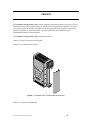
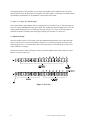
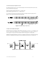
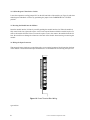
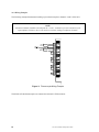
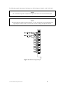
CTI 2451 EIGHT CHANNEL
THERMOCOUPLE INPUT MODULE
INSTALLATION AND OPERATION GUIDE
Version 1.2
CTI Part #062-00111
2451IOG 051403
$25
Copyright © 2003 Control Technology Inc.
All rights reserved.
This manual is published by Control Technology Inc., 5734 Middlebrook Pike, Knoxville, TN 37921.
This manual contains references to brand and product names which are tradenames, trademarks, and/or
registered trademarks of Control Technology Inc. Siemens® and SIMATIC® are registered trademarks
of Siemens AG. Other references to brand and product names are tradenames, trademarks, and/or
registered trademarks of their respective holders.
DOCUMENT DISCLAIMER STATEMENT
Every effort has been made to ensure the accuracy of this document; however, errors do occasionally
occur. CTI provides this document on an "as is" basis and assumes no responsibility for direct or
consequential damages resulting from the use of this document. This document is provided without
express or implied warranty of any kind, including but not limited to the warranties of merchantiblility or
fitness for a particular purpose. This document and the products it references are subject to change
without notice. If you have a comment or discover an error, please call us toll-free at 1-800-537-8398.
ii
CTI 2451 Installation and Operation Guide
PREFACE
This Installation and Operation Guide provides installation and operation instructions for the CTI 2451
Eight Channel Thermocouple Input Module for SIMATIC® 405 programmable controllers. We assume
you are familiar with the operation of SIMATIC® 405 Series programmable controllers. Refer to the
appropriate SIMATIC® user documentation for specific information on the SIMATIC® 405
programmable controllers and I/O modules.
This Installation and Operation Guide is organized as follows:
Chapter 1 provides a description of the module.
Chapter 2 covers installation and wiring.
Figure 1 The Model 2451 Thermocouple Input Module
Chapter 3 is a guide to troubleshooting.
CTI 2451 Installation and Operation Guide
iii
iv
CTI 2451 Installation and Operation Guide
USAGE CONVENTIONS
NOTE:
Notes alert the user to special features or procedures.
CAUTION:
Cautions alert the user to procedures which could damage equipment.
WARNING:
Warnings alert the user to procedures which could damage equipment and endanger the user.
CTI 2451 Installation and Operation Guide
v
vi
CTI 2451 Installation and Operation Guide
TABLE OF CONTENTS
PREFACE . . . . . . . . . . . . . . . . . . . . . . . . . . . . . . . . . . . . . . . . . . . . . . . . . . . . . . . . . . . . . . . . . . . . . . . . . . iii
USAGE CONVENTIONS . . . . . . . . . . . . . . . . . . . . . . . . . . . . . . . . . . . . . . . . . . . . . . . . . . . . . . . . . . . .
v
TABLE OF FIGURES . . . . . . . . . . . . . . . . . . . . . . . . . . . . . . . . . . . . . . . . . . . . . . . . . . . . . . . . . . . . . . . . ix
CHAPTER 1. DESCRIPTION . . . . . . . . . . . . . . . . . . . . . . . . . . . . . . . . . . . . . . . . . . . . . . . . . . . . . . . . .
1.1 Asynchronous Operation . . . . . . . . . . . . . . . . . . . . . . . . . . . . . . . . . . . . . . . . . . . . . . . . . . . .
1.1.1 Active Channels . . . . . . . . . . . . . . . . . . . . . . . . . . . . . . . . . . . . . . . . . . . . . . . . . .
1.2 Type "J" or Type "K" Thermocouple . . . . . . . . . . . . . . . . . . . . . . . . . . . . . . . . . . . . . . . . . .
1.3 Digital Word Map . . . . . . . . . . . . . . . . . . . . . . . . . . . . . . . . . . . . . . . . . . . . . . . . . . . . . . . . .
1.4 Thermocouple Input to Digital Conversion . . . . . . . . . . . . . . . . . . . . . . . . . . . . . . . . . . . . . .
1.5 Effect of Out-of Range Input Signals . . . . . . . . . . . . . . . . . . . . . . . . . . . . . . . . . . . . . . . . . .
1.6 Resolution . . . . . . . . . . . . . . . . . . . . . . . . . . . . . . . . . . . . . . . . . . . . . . . . . . . . . . . . . . . . . . .
1
1
1
2
2
3
3
4
CHAPTER 2. INSTALLATION . . . . . . . . . . . . . . . . . . . . . . . . . . . . . . . . . . . . . . . . . . . . . . . . . . . . . . .
2.1 Planning the Installation . . . . . . . . . . . . . . . . . . . . . . . . . . . . . . . . . . . . . . . . . . . . . . . . . . . .
2.2 Calculating the I/O Base Power Budget . . . . . . . . . . . . . . . . . . . . . . . . . . . . . . . . . . . . . . . .
2.3 Unpacking the Module . . . . . . . . . . . . . . . . . . . . . . . . . . . . . . . . . . . . . . . . . . . . . . . . . . . . .
2.4 Configuring the Module . . . . . . . . . . . . . . . . . . . . . . . . . . . . . . . . . . . . . . . . . . . . . . . . . . . . .
2.4.1 Select Millivolt or Temperature Input . . . . . . . . . . . . . . . . . . . . . . . . . . . . . . . . . .
2.4.2 Selecting Type "J" or Type "K" Thermocouple Inputs . . . . . . . . . . . . . . . . . . . . .
2.4.3 Selecting Digital Filtering . . . . . . . . . . . . . . . . . . . . . . . . . . . . . . . . . . . . . . . . . . .
2.4.4 Select Degrees Fahrenheit or Celsius . . . . . . . . . . . . . . . . . . . . . . . . . . . . . . . . . .
2.5 Inserting the Module into the I/O Base . . . . . . . . . . . . . . . . . . . . . . . . . . . . . . . . . . . . . . . . .
2.6 Wiring the Input Connectors . . . . . . . . . . . . . . . . . . . . . . . . . . . . . . . . . . . . . . . . . . . . . . . . .
2.6.1 Wiring Guidelines . . . . . . . . . . . . . . . . . . . . . . . . . . . . . . . . . . . . . . . . . . . . . . . . .
2.6.2 Wiring Examples . . . . . . . . . . . . . . . . . . . . . . . . . . . . . . . . . . . . . . . . . . . . . . . . . .
2.7 I/O Configuration and Input Format . . . . . . . . . . . . . . . . . . . . . . . . . . . . . . . . . . . . . . . . . . .
2.7.1 Octal Numbering . . . . . . . . . . . . . . . . . . . . . . . . . . . . . . . . . . . . . . . . . . . . . . . . . .
2.7.2 Input Format . . . . . . . . . . . . . . . . . . . . . . . . . . . . . . . . . . . . . . . . . . . . . . . . . . . . .
2.7.3 Operating the Module . . . . . . . . . . . . . . . . . . . . . . . . . . . . . . . . . . . . . . . . . . . . . .
2.8 Decoding Channels . . . . . . . . . . . . . . . . . . . . . . . . . . . . . . . . . . . . . . . . . . . . . . . . . . . . . . . .
2.9 Checking Module Operation . . . . . . . . . . . . . . . . . . . . . . . . . . . . . . . . . . . . . . . . . . . . . . . . .
5
5
5
5
6
7
7
7
8
8
8
9
10
12
12
12
13
14
15
CHAPTER 3. TROUBLESHOOTING . . . . . . . . . . . . . . . . . . . . . . . . . . . . . . . . . . . . . . . . . . . . . . . . . . 17
SPECIFICATIONS . . . . . . . . . . . . . . . . . . . . . . . . . . . . . . . . . . . . . . . . . . . . . . . . . . . . . . . . . . . . . . . . . . 19
LIMITED PRODUCT WARRANTY . . . . . . . . . . . . . . . . . . . . . . . . . . . . . . . . . . . . . . . . . . . . . . . . . . . 23
REPAIR POLICY . . . . . . . . . . . . . . . . . . . . . . . . . . . . . . . . . . . . . . . . . . . . . . . . . . . . . . . . . . . . . . . . . . . 25
CTI 2451 Installation and Operation Guide
vii
viii
CTI 2451 Installation and Operation Guide
TABLE OF FIGURES
Figure 1 The Model 2451 Thermocouple Input Module . . . . . . . . . . . . . . . . . . . . . . . . . . . . . . . . . . . . . . iii
Figure 2 Active Channels . . . . . . . . . . . . . . . . . . . . . . . . . . . . . . . . . . . . . . . . . . . . . . . . . . . . . . . . . . . . . 1
Figure 3 Word Map . . . . . . . . . . . . . . . . . . . . . . . . . . . . . . . . . . . . . . . . . . . . . . . . . . . . . . . . . . . . . . . . . 2
Figure 4 Example Change in Input Level . . . . . . . . . . . . . . . . . . . . . . . . . . . . . . . . . . . . . . . . . . . . . . . . 3
Figure 5 Effect of Temperature Input on Module Performance . . . . . . . . . . . . . . . . . . . . . . . . . . . . . . . 3
Figure 6 Effect of Voltage Input on Module Performance . . . . . . . . . . . . . . . . . . . . . . . . . . . . . . . . . . . 4
Figure 7 Input Resolution . . . . . . . . . . . . . . . . . . . . . . . . . . . . . . . . . . . . . . . . . . . . . . . . . . . . . . . . . . . . 4
Figure 8 Jumper Locations . . . . . . . . . . . . . . . . . . . . . . . . . . . . . . . . . . . . . . . . . . . . . . . . . . . . . . . . . . . 6
Figure 9 Factory Configuration Jumper Settings . . . . . . . . . . . . . . . . . . . . . . . . . . . . . . . . . . . . . . . . . . 7
Figure 10 Screw Terminal Block Wiring . . . . . . . . . . . . . . . . . . . . . . . . . . . . . . . . . . . . . . . . . . . . . . . . . 8
Figure 11 Thermocouple Wiring Example . . . . . . . . . . . . . . . . . . . . . . . . . . . . . . . . . . . . . . . . . . . . . . . . 10
Figure 12 Millivolt Wiring Example . . . . . . . . . . . . . . . . . . . . . . . . . . . . . . . . . . . . . . . . . . . . . . . . . . . . 11
Figure 13 Unused Bits . . . . . . . . . . . . . . . . . . . . . . . . . . . . . . . . . . . . . . . . . . . . . . . . . . . . . . . . . . . . . . . 12
Figure 14 Active Channel Bits . . . . . . . . . . . . . . . . . . . . . . . . . . . . . . . . . . . . . . . . . . . . . . . . . . . . . . . . . 12
Figure 15 Data Word . . . . . . . . . . . . . . . . . . . . . . . . . . . . . . . . . . . . . . . . . . . . . . . . . . . . . . . . . . . . . . . . 13
Figure 16 Example Measurement . . . . . . . . . . . . . . . . . . . . . . . . . . . . . . . . . . . . . . . . . . . . . . . . . . . . . . 13
Figure 17 Ladder Diagram Example . . . . . . . . . . . . . . . . . . . . . . . . . . . . . . . . . . . . . . . . . . . . . . . . . . . . 14
CTI 2451 Installation and Operation Guide
ix
x
CTI 2451 Installation and Operation Guide
CHAPTER 1. DESCRIPTION
The Model 2451 Eight Channel Thermocouple Input Module is a member of Control Technology's family
of I/O modules compatible with the SIMATIC® 405 Series programmable controllers. The Model 2451
is designed to translate Type "J" thermocouples, Type "K" thermocouples and millivolt input signals into
equivalent digital words which are then sent to the programmable controller (PLC).
The Model 2451 Thermocouple Input Module features built-in cold junction compensation for each
thermocouple input. Support for other thermocouple types is available through special request from the
factory. Call CTI at 1-800-537-8398 to determine if support is available for your special thermocouple
type.
1.1 Asynchronous Operation
The module operates asynchronously with the CPU. That is, the update times of the CPU and module do
not occur simultaneously. The module converts all selected thermocouple inputs in one module update
(which is less than 3.0 milliseconds per selected channel), and stores the digital information in a buffer.
1.1.1 Active Channels
One of the channels is considered to be active during each CPU scan. On any given CPU scan, both an
indicator describing which channel is active and the information for the active channel is transferred
from the module to the CPU. Following the transfer, the channel is deactivated and the next selected
channel automatically becomes active. The next CPU scan triggers the active channel indicator and data
for this channel and sends it to the CPU; this process repeats. Eight CPU scans are required to obtain
data from all eight channels. Thus, although the module itself performs conversion asynchronously with
the CPU, the transmission of data from the module to the CPU is asynchronous with the CPU scan. This
process is illustrated in the following figure.
Figure 2 Active Channels
CTI 2451 Installation and Operation Guide
1
The module appears to the controller as 32 X inputs. The module can be installed in any slot of any
Series 405 base. Since the Series 405 CPU supports 320 total X inputs, a maximum of 10 thermocouple
input modules (80 channels) can be installed in a single Series 405 system.
1.2 Type "J" or Type "K" Thermocouple
Each of the module's eight channels may be configured to receive either a Type "J" Thermocouple or a
Type "K" non-grounded thermocouple input signal. The module may also be configured to receive DC
voltage signals ranging from 0 to 55 millivolts. Selection of Type "J" or Type "K" thermocouples or
millivolts are made via internal switch and jumper settings (see Sections 2.4.1 and 2.4.3).
1.3 Digital Word Map
Since the module requires a 32-bit input word, the temperature/millivolt data value is placed into the
lower 16-bits (bits 0-17 octal) for transmittal to the PLC (as a V-memory location). As shown in the
following figure, bit 17 is not used for the data value and is always 0. The LSB (bit 0) is used to note
values which are "overrange".
The first 8 bits (20-27 octal) of the upper 16 bits are used for channel status and are read as X values.
Bits 30-37 (octal) are not used.
Figure 3 Word Map
2
CTI 2451 Installation and Operation Guide
1.4 Thermocouple Input to Digital Conversion
The following equations may be used to calculate the digital word in decimal format which will result
from a particular thermocouple input:
Thermocouple Mode, Digital Word (bits 0-17) = Degrees X10
Millivolt Mode, Digital Word (bits 0-17) = Millivolts X100
As an example, the following figure illustrates the effects of a change in input level going from 3.2
degrees to 102.4 degrees in the Thermocouple Input Mode.
Figure 4 Example Change in Input Level
1.5 Effect of Out-of Range Input Signals
Thermocouple inputs exceeding the ANSI standard of 760 degrees C for Type "J" or 1372 degrees C for
Type "K" will cause the overrange bit to be set. A maximum temperature of 761 degrees C for Type "J"
or 1373 degrees C for Type "K" will be returned to the PLC for any positive overrange input.
Similarily an input below 0 degrees C for Type "J" or 0 degrees C for Type "K" will cause the overrange
bit to be set. A temperature of 0.1 degree C will be returned to the PLC for Type "J" and Type "K".
Figure 5 Effect of Temperature Input on Module Performance
CTI 2451 Installation and Operation Guide
3
Millivolt inputs exceeding 55.00 millivolts will cause the overrange bit to be set. A reading of 55.01
millivolts will be returned to the PLC for any positive overrange input.
Similarly a millivolt input below 0 millivolts will cause the overrange bit to be set. A reading of 0.01
millivolt will be returned to the PLC for any negative input.
Figure 6 Effect of Voltage Input on Module Performance
1.6 Resolution
The module has a resolution of approximately 0.2 degrees C, 0.4 degrees F or exactly 0.02 millivolts.
The chart below shows the corresponding input resolution for each of the input configuration modes:
Figure 7 Input Resolution
4
CTI 2451 Installation and Operation Guide
CHAPTER 2. INSTALLATION
The installation of the Eight Channel Thermocouple Input Module involves the following steps:
1. Planning the installation
2. Configuring the module
3. Inserting the module into the I/O base
4. Wiring the module input connector
5. Checking module operation
The steps listed above are explained in detail in the following pages.
2.1 Planning the Installation
Planning is the first step in the installation of the module. This involves calculating the I/O base power
budget and routing the input signal wiring to minimize noise. The following sections discuss these
important considerations.
2.2 Calculating the I/O Base Power Budget
The Model 2451 requires 2.8 watts of +5V power from the I/O base. Use this figure to verify that the
base power supply capacity is not exceeded.
2.3 Unpacking the Module
Open the shipping carton and remove the special anti-static bag which contains the module.
After discharging any static build-up, remove the module from the anti-static bag. Do not discard the
anti-static bag. You will need it for the following configuration procedure.
CTI 2451 Installation and Operation Guide
5
2.4 Configuring the Module
The Model 2451 must be configured for Type "J" or Type "K" non-grounded thermocouples or millivolt
range and digital filtering/no filtering mode before wiring the input connectors and inserting the module
into the I/O base. As shipped, all input channels are configured Type "J", thermocouples, degrees Celsius
and digital filtering enabled (see Figure 8).
Changing the module input channel configuration involves the following steps:
1. Select millivolt or temperature input
2. Selecting Type "J" or Type "K" thermocouple input mode for each channel
3. Selecting digital filtering or no filtering for the module
4. Logging the configuration jumper settings for future reference
Each of these steps is described in the following sections.
CAUTION:
DO NOT attempt to calibrate.
Figure 8 Jumper Locations
6
CTI 2451 Installation and Operation Guide
2.4.1 Select Millivolt or Temperature Input
Locate jumper JP36 (MILLIVOLT/TEMP jumper in Figure 8) on the 2451 card. Select either Millivolts
or Temperature for the module by positioning the jumper in MILLIVOLT or TEMP position. In the
millivolt mode, jumpers JP1-16, JP35 and DIP switch SW1 are ignored by the 2451.
2.4.2 Selecting Type "J" or Type "K" Thermocouple Inputs
Select the cold junction compensation for each channel by selecting the correct jumper (JP1-16) for each
channel.
Select the correct linearization table by locating by DIP switch 1 (SW1 in Figure 8) on the 2451 circuit
card and select either Type "J" or Type "K" thermocouple for each of the eight inputs by moving each
switch to the proper position. The "ON" position corresponds to Type "J" thermocouple input.
2.4.3 Selecting Digital Filtering
Locate the Digital Filtering Jumper JP34 (see Figure 8). To enable digital filtering, set the jumper in the
ENABLED position. Since many analog input signals contain noise, CTI recommends using digital
filtering unless maximum response time is required.
Figure 9 Factory Configuration Jumper Settings
CTI 2451 Installation and Operation Guide
7
2.4.4 Select Degrees Fahrenheit or Celsius
Locate the temperature scaling jumper JP35 on the left hand side of the module (see Figure 8) and select
either degrees Fahrenheit or Celsius by positioning the jumper in the FAHRENHEIT or CELSIUS
position.
2.5 Inserting the Module into the I/O Base
Insert the module into the I/O base by carefully pushing the module into the slot. When the module is
fully seated in the slot, tighten the captive screws at the top and bottom to hold the module in place. To
remove the module from the I/O base, loosen the captive screws, then remove the module from the I/O
base. Be careful not to damage the connector at the back of the module when inserting or removing the
module.
2.6 Wiring the Input Connectors
Thermocouple input signals are accepted through a screw terminal connector block located on the front
of the module. Consult the thermocouple manufacturer's recommendations for selecting the input wire
Figure 10 Screw Terminal Block Wiring
type and size.
8
CTI 2451 Installation and Operation Guide
All GND terminals on the 2451 terminal block (see Figure 10) are common to each other. They are
provided as a convenient termination point for cable shields. All input terminals are isolated from the PLC
up to 1500VDC.
CAUTION:
Only non-grounded thermocouples are to be used.
2.6.1 Wiring Guidelines
To avoid noise problems, follow these guidelines when installing the module.
!
Use the shortest possible wires.
!
Avoid placing signal wires parallel to high-energy wires. If the two must meet, cross them
at right angles.
!
Avoid bending the wire into sharp angles.
!
Use wireways for wire routing.
!
When using shielded wires, ground them only at the module end for better noise
immunity.
!
Place wires so that they do not interfere with existing wire.
CTI 2451 Installation and Operation Guide
9
2.6.2 Wiring Examples
The following example demonstrates hooking up two thermocouples to channels 1 and 2 of the 2451.
NOTE:
All unused channels should be shorted from the + to the - terminals to prevent saturation of the
input amplifier. Failure to do so will result in erroneous readings on adjacent channels.
Figure 11 Thermocouple Wiring Example
The shields of both thermocouples are connected to terminal 3 GND connector.
10
CTI 2451 Installation and Operation Guide
The following example demonstrates hooking up two millivolt inputs to channels 1 and 2 of the 2451.
NOTE:
The - terminal incorporates cold junction compensation and is not used on millivolt inputs.
NOTE:
All unused channels should be shorted from the + to the - terminals to prevent saturation of the
input amplifier. Failure to do so will result in erroneous readings on adjacent channels.
Figure 12 Millivolt Wiring Example
CTI 2451 Installation and Operation Guide
11
2.7 I/O Configuration and Input Format
2.7.1 Octal Numbering
Series 405 I/O references are numbered in octal (also known as base 8). In octal, the digits 8 and 9 are
not used. I/O points are counted as usual from 0 up to 7. Since 8 and 9 are not used, the next point after
7 is 10. When the count reaches 17, the next point is 20. The point following 77 is 100.
2.7.2 Input Format
The module appears to the controller as 32 X inputs.
To allow the automatic I/O configuration to reserve points X0 through X37 for the module (for a total of
32 points), install the module in the first slot of the first base.
The module reserves points Xn through Xn + 37 (octal), where n is the starting point number. These 32
X inputs or bits are defined as shown in Figure 13, which also shows the most significant bit (MSB) and
the least significant bit (LSB).
As shown in Figure 13, the eight highest X locations (Xn + 30 through Xn + 37) are not used by this
Figure 13 Unused Bits
module.
The next highest eight bits (Xn + 20 through Xn + 27) are used by the module to indicate the active
channel (as shown in Figure 14). The data bits from one channel and only one channel are transferred to
Figure 14 Active Channel Bits
the CPU with each CPU scan. The active channel indicators indentify which channel corresponds to
those data bits.
12
CTI 2451 Installation and Operation Guide
CTI 2451 Installation and Operation Guide
13
Data bits Xn + 1 through Xn + 16 contain the temperature data of the active channel. Data bit Xn +0 is
the overrange bit. Data bit Xn + 17 is not used (see Figure 13).
Figure 15 Data Word
2.7.3 Operating the Module
For example, the 32 bits given in Figure 15 might be read by the CPU during a scan. Since Xn + 23
contains a 1, channel 4 is active. Thus, the data given in bits Xn + 0 through Xn + 16 belong to channel
4. Data bits 7, 4, and 3 contain a 1, so the data value would be (128 + 16 + 8) 152 and the temperature
would be 15.2 degrees (or millivolts range would be 1.52 millivolts).
The active channel is automatically incremented to the next selected channel with each CPU scan. The
conversion of the analog signals to digital data is asynchronous with the CPU. However, the transfer of
data from the module to the CPU is synchronous with the CPU scan. That is, the selected channels are
presented to the CPU one at a time (one per CPU scan) in a cyclic fashion.
Figure 16 Example Measurement
14
CTI 2451 Installation and Operation Guide
2.8 Decoding Channels
Since data from all channels are multiplexed into a single word, you might wish to write a program to
decode the information for each channel, as shown in the following figure. This program decodes
information from the eight channels and stores it in V-memory. Channel 1 is stored in V2000, channel 2
in V2001, etc. This program assumes the module is configured as X0-X37.
X0-X17 can be read as V-memory location 40400. Refer to the memory map in the Series 405 User
Manual for details.
NOTE:
Only one channel is accessed per CPU scan. The active channel is incremented to the next selected
channel following each CPU scan.
Figure 17 Ladder Diagram Example
CTI 2451 Installation and Operation Guide
15
2.9 Checking Module Operation
First turn on the base supply power. If the module diagnostics detect no problems, the status indicator
on the front of the module will light. If the status indicator does not light (or goes out during operation),
the module has detected a failure. For information on viewing failed module status, refer to your
SIMATIC® TISOFT user manual. To diagnose and correct a module failure, refer to troubleshooting.
You must also check that the module is configured in the memory of the PLC. This is important because
the module will appear to be functioning regardless of whether it is communicating with the PLC. To
view the PLC memory configuration chart listing all slots on the base and the inputs or outputs
associated with each slot, refer to your SIMATIC® TISOFT Programming Manual. An example chart is
shown in the following figure.
In this example, the 2451 module is inserted in slot 0 in I/O base 0. Data for all channels appears in Vmemory location V40400. See Section 2.8 for a sample program to decode the data for individual
channels. If 32 point input module appears on this line, then the module is registered in the PLC memory
and the module is ready for operation.
I/O MODULE DEFINITION FOR BASE . . . . . 0
SLOT
ADDRESS
IN
OUT
0 . . . . . . . 0000A
(435) : 32 PT INPUT MOD
1 . . . . . . . 0000A
(435) : EMPTY I/O SLOT
2 . . . . . . . 0000A
(435) : EMPTY I/O SLOT
3 . . . . . . . 0000A
(435) : EMPTY I/O SLOT
4 . . . . . . . 0000A
(435) : EMPTY I/O SLOT
5 . . . . . . . 0000A
(435) : EMPTY I/O SLOT
6 . . . . . . . 0000A
(435) : EMPTY I/O SLOT
7 . . . . . . . 0000A
(435) : EMPTY I/O SLOT
IN
OUT
POINTS
ID
MODULE
NAME
. . 0000A . . . . 32 . . . 00 . . . . . . . . 3F . . . . . . . . .
. . 0000A . . . . 00 . . . 00 . . . . . . . . FF . . . . . . . . .
. . 0000A . . . . 00 . . . 00 . . . . . . . . FF . . . . . . . . .
. . 0000A . . . . 00 . . . 00 . . . . . . . . FF . . . . . . . . .
. . 0000A . . . . 00 . . . 00 . . . . . . . . FF . . . . . . . . .
. . 0000A . . . . 00 . . . 00 . . . . . . . . FF . . . . . . . . .
. . 0000A . . . . 00 . . . 00 . . . . . . . . FF . . . . . . . . .
. . 0000A . . . . 00 . . . 00 . . . . . . . . FF . . . . . . . . .
BASE . . . . . . . . . . . . . . . . . . . . . . . . . . . . . . . . . . . . . . . . . . . 03 . . . . . . . . .
(435) : I/O BASE
CPU . . . . . . . . . . . . . . . . . . . . . . . . . . . . . . . . . . . . . . . . . . . 01 . . . . . . . . .
(435) : CPU AND P/S
PS . . . . . . . . . . . . . . . . . . . . . . . . . . . . . . . . . . . . . . . . . . . . 01 . . . . . . . . .
(435) : CPU AND P/S
FROM P/C
435
RUN
EXIT-F1
READDK-F3 WRITDK-F4 READPC-F5 WRITPC-F6 AU/MAN-F7 CLRBS-
F8
16
CTI 2451 Installation and Operation Guide
Example I/O Configuration Chart
If the line is listed as an empty slot or shows erroneous data, re-check the module to ensure that it is
firmly seated in the slots. Generate the PLC memory configuration chart again. If the line is still
incorrect, contact your local distributor or CTI at 1-800-537-8398 for futher assistance.
CTI 2451 Installation and Operation Guide
17
18
CTI 2451 Installation and Operation Guide
CHAPTER 3. TROUBLESHOOTING
SYMPTOM
Indicator is not lit
PROBABLE CAUSE
Base or PC power is off
Incorrect inputs
CORRECTIVE ACTION
Turn base or PC on
Defective module
Return the module to
CTI for service
Wrong addresses for word input
Check program for correct
word input addresses
Wrong connections
Trace wiring to check connections
Not logged-in
Read I/O configuration
Incorrectly calibrated
Return the module to CTI
for recalibration
Blown fuse
Return the module to CTI
for service
Troubleshooting Matrix
CAUTION:
The module fuse is not user serviceable. If this fuse is blown, the module has a serious component
failure and should be returned to CTI for repair.
When it is inconvenient to visually check the status indicator, use the SIMATIC® TISOFT "Display
Failed I/O" or "Show PLC Diagnostics" support functions.
If after consulting the chart above and you are unable to diagnose or solve the problem, contact your
local distributor or CTI at 1-800-537-8398 for further assistance.
CTI 2451 Installation and Operation Guide
19
20
CTI 2451 Installation and Operation Guide
SPECIFICATIONS
Channels Per Module:
Eight
Size:
Single wide 405 module
Standard Thermocouple Types:
Type "J"
0° to 760°C
32° to 1400°F
Type "K"
0° to 1372°C
32° to 2501°F
Special Order Types:
Consult Control Technolgy Inc. 1-800-537-8398
Absolute Temp Accuracy:
±1°C
±2°F
Temperature Resolution:
Approx. 0.2°C
Approx. 0.6°F
Millivolt Range:
0 to 55 Millivolts
Millivolt Input Impedance:
Greater than 10 KS @ 60 Hz
Greater than 1000 Megohm @ DC
Absolute Millivolt Accuracy:
±0.1 percent full scale or ±55µV
Millivolt Resolution:
0.02 mV
Repeatability:
.05% Full scale (temp or mV)
Common Mode Rejection:
Greater than 110 dB @ 60 Hz (digital filtering disabled)
Greater than 160 dB @ 60 Hz (digital filtering enabled)
Normal Mode Rejection:
Greater than 45 dB @ 60 Hz (digital filtering enabled)
CTI 2451 Installation and Operation Guide
21
Input Protection:
4000 Volts ESD
±20 VDC from any input to channel common
±20 VDC from any input to any other input on same channel
Input Bandwidth:
5.5 Hz (digital filtering disabled)
0.16 Hz (digital filtering enabled)
Filtering Time Constant:
(50 mV input step)
18 mSec (digital filtering disabled)
1.0 Sec (digital filtering enabled)
Update Time:
24 milliseconds for all eight channels
Open Thermocouple Reporting:
To PLC as bit number one set
Module Power from Base:
2.8 watts @ +5VDC
Isolation:
1500 VDC channel-to-PLC
Field Wiring Connector:
Accepts 14-26 AWG
Mechanical:
Size single-wide 405 module
Operating Temperature:
0° to 60°C
32° to 140°F
Relative Humidity:
5% to 95% non-condensing
Shipping Weight:
0.5 lbs.
Specifications subject to change without notice.
22
CTI 2451 Installation and Operation Guide
USER NOTES
CTI 2451 Installation and Operation Guide
23
24
CTI 2451 Installation and Operation Guide
LIMITED PRODUCT WARRANTY
CTI warrants that this CTI Industrial Product shall be free from defects in material and workmanship for
a period of one (1) year after purchase from CTI or from an authorized CTI Industrial Distributor. This
CTI Industrial Product will be newly manufactured from new and/or serviceable used parts which are
equal to new in the Product.
Should this CTI Industrial Product fail to be free from defects in material and workmanship at any time
during this one (1) year warranty period, CTI will repair or replace (at its option) parts or Products
found to be defective and shipped prepaid by the customer to a designated CTI service location along
with proof of purchase date and associated serial number. Repair parts and replacement Product
furnished under this warranty will be on an exchange basis and will be either reconditioned or new. All
exchanged parts or Products become the property of CTI. Should any Product or part returned to CTI
hereunder be found by CTI to be without defect, CTI will return such Product or part to the customer.
This warranty does not include repair of damage to a part or the Product resulting from: failure to
provide a suitable environment as specified in applicable Product specifications, or damage caused by an
accident, disaster, acts of God, neglect, abuse, misuse, transportation, alterations, attachments,
accessories, supplies, non-CTI parts, non-CTI repairs or activities, or to any damage whose proximate
cause was utilities or utility like services, or faulty installation or maintenance done by someone other
than CTI.
Control Technology Inc. reserves the right to make changes to the Product in order to improve reliability,
function, or design in the pursuit of providing the best possible Product. CTI assumes no responsibility
for indirect or consequential damages resulting from the use or application of this equipment.
THE WARRANTY SET FORTH ABOVE IN THIS ARTICLE IS THE ONLY WARRANTY CTI
GRANTS AND IT IS IN LIEU OF ANY OTHER IMPLIED OR EXPRESSED GUARANTY OR
WARRANTY ON CTI PRODUCTS, INCLUDING WITHOUT LIMITATION, ANY WARRANTY
OF MERCHANTABILITY OR OF FITNESS FOR A PARTICULAR PURPOSE AND IS IN LIEU
OF ALL OBLIGATIONS OR LIABILITY OF CTI FOR DAMAGES IN CONNECTION WITH
LOSS, DELIVERY, USE OR PERFORMANCE OF CTI PRODUCTS OR INTERRUPTION OF
BUSINESS, LOSS OF USE, REVENUE OR PROFIT. IN NO EVENT WILL CTI BE LIABLE FOR
SPECIAL, INCIDENTAL, OR CONSEQUENTIAL DAMAGES.
SOME STATES DO NOT ALLOW THE EXCLUSION OR LIMITATION OF INCIDENTAL OR
CONSEQUENTIAL DAMAGES FOR CONSUMER PRODUCTS, SO THE ABOVE LIMITATIONS OR
EXCLUSIONS MAY NOT APPLY TO YOU.
THIS WARRANTY GIVES YOU SPECIFIC LEGAL RIGHTS, AND YOU MAY ALSO HAVE OTHER
RIGHTS WHICH MAY VARY FROM STATE TO STATE.
CTI 2451 Installation and Operation Guide
25
26
CTI 2451 Installation and Operation Guide
REPAIR POLICY
In the event that the Product should fail during or after the warranty period, a Return Material
Authorization (RMA) number can be requested verbally or in writing from CTI main offices. Whether
this equipment is in or out of warranty, a Purchase Order number provided to CTI when requesting the
RMA number will aid in expediting the repair process. The RMA number that is issued and your
Purchase Order number should be referenced on the returning equipment's shipping documentation.
Additionally, if under warranty, proof of purchase date and serial number must accompany the returned
equipment. The current repair and/or exchange rates can be obtained by contacting CTI's main office at
1-800-537-8398.
When returning any module to CTI, follow proper static control precautions. Keep the module away
from polyethylene products, polystyrene products and all other static producing materials. Packing the
module in its original conductive bag is the preferred way to control static problems during shipment.
Failure to observe static control precautions may void the warranty. For additional information on
static control precautions, contact CTI's main office at 1-800-537-8398.
CTI 2451 Installation and Operation Guide
27