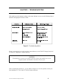
1
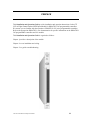
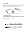
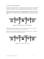
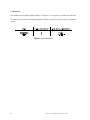
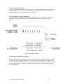
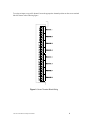
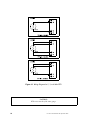
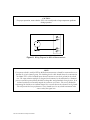
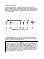
CTI 2552-A
8-CHANNEL ISOLATED RTD INPUT MODULE
INSTALLATION AND OPERATION GUIDE
Ver. 1.2
CTI Part # 062-00306-012
062-00303-011
2552-AIOG
020106
$25
Copyright © 2006 Control Technology Inc.
All rights reserved.
This manual is published by Control Technology Inc., 5734 Middlebrook Pike, Knoxville, TN 37921.
This manual contains references to brand and product names which are tradenames, trademarks,
and/or registered trademarks of Control Technology Inc. Siemens® and SIMATIC® are registered
trademarks of Siemens AG. Other references to brand and product names are tradenames,
trademarks, and/or registered trademarks of their respective holders.
DOCUMENT DISCLAIMER STATEMENT
Every effort has been made to ensure the accuracy of this document; however, errors do occasionally
occur. CTI provides this document on an "as is" basis and assumes no responsibility for direct or
consequential damages resulting from the use of this document. This document is provided without
express or implied warranty of any kind, including but not limited to the warranties of
merchantability or fitness for a particular purpose. This document and the products it references are
subject to change without notice. If you have a comment or discover an error, please call us toll-free
at 1-800-537-8398.
ii
CTI 2552-A Installation and Operation Guide
PREFACE
This Installation and Operation Guide provides installation and operation instructions for the CTI
2552-A Eight Channel Isolated RTD Input Module for SIMATIC® 505 programmable controllers.
We assume you are familiar with the operation of SIMATIC® 505 series programmable controllers.
Refer to the appropriate SIMATIC® user documentation for specific information on the SIMATIC®
505 programmable controllers and I/O modules.
This Installation and Operation Guide is organized as follows:
Chapter 1 provides a description of the module.
Chapter 2 covers installation and wiring.
Chapter 3 is a guide to troubleshooting.
CTI 2552-A Installation and Operation Guide
iii
iv
CTI 2552-A Installation and Operation Guide
TABLE OF CONTENTS
PREFACE . . . . . . . . . . . . . . . . . . . . . . . . . . . . . . . . . . . . . . . . . . . . . . . . . . . . . . . . . . . . . . . . . . . . . . iii
TABLE OF FIGURES . . . . . . . . . . . . . . . . . . . . . . . . . . . . . . . . . . . . . . . . . . . . . . . . . . . . . . . . . . . vii
USAGE CONVENTIONS . . . . . . . . . . . . . . . . . . . . . . . . . . . . . . . . . . . . . . . . . . . . . . . . . . . . . . . . ix
CHAPTER 1. DESCRIPTION . . . . . . . . . . . . . . . . . . . . . . . . . . . . . . . . . . . . . . . . . . . . . . . . . . . . .
1.1 Asynchronous Operation . . . . . . . . . . . . . . . . . . . . . . . . . . . . . . . . . . . . . . . . . . . . . . . .
1.1.1 Compatibility with Immediate I/O . . . . . . . . . . . . . . . . . . . . . . . . . . . . . . . .
1.2 100 Ohm or 120 Ohm RTDs . . . . . . . . . . . . . . . . . . . . . . . . . . . . . . . . . . . . . . . . . . . . .
1.3 Digital Word Map . . . . . . . . . . . . . . . . . . . . . . . . . . . . . . . . . . . . . . . . . . . . . . . . . . . . .
1.4 RTD Input to Digital Conversion . . . . . . . . . . . . . . . . . . . . . . . . . . . . . . . . . . . . . . . . . .
1.5 Effect of Out-of-Range Input Signals . . . . . . . . . . . . . . . . . . . . . . . . . . . . . . . . . . . . . . .
1.6 Resolution . . . . . . . . . . . . . . . . . . . . . . . . . . . . . . . . . . . . . . . . . . . . . . . . . . . . . . . . . . . .
1
1
1
1
2
2
3
4
CHAPTER 2. INSTALLATION . . . . . . . . . . . . . . . . . . . . . . . . . . . . . . . . . . . . . . . . . . . . . . . . . . . 5
2.1 Planning the Installation . . . . . . . . . . . . . . . . . . . . . . . . . . . . . . . . . . . . . . . . . . . . . . . . . 5
2.2 Calculating the I/O Base Power Budget . . . . . . . . . . . . . . . . . . . . . . . . . . . . . . . . . . . . . 5
2.3 Unpacking the Module . . . . . . . . . . . . . . . . . . . . . . . . . . . . . . . . . . . . . . . . . . . . . . . . . . 5
2.4 Configuring the Module . . . . . . . . . . . . . . . . . . . . . . . . . . . . . . . . . . . . . . . . . . . . . . . . . 6
2.4.1 Select Temperature or Millivolt Input . . . . . . . . . . . . . . . . . . . . . . . . . . . . . . 6
2.4.2 Selecting 3 Wire or 4 Wire Operation . . . . . . . . . . . . . . . . . . . . . . . . . . . . . . 6
2.4.3 Selecting 100 Ohm or 120 Ohm RTD Inputs . . . . . . . . . . . . . . . . . . . . . . . . 6
2.4.4 Selecting Digital Filtering . . . . . . . . . . . . . . . . . . . . . . . . . . . . . . . . . . . . . . . 7
2.4.5 Select Degrees Celsius or Fahrenheit . . . . . . . . . . . . . . . . . . . . . . . . . . . . . . 7
2.5 Inserting the Module Into the I/O Base . . . . . . . . . . . . . . . . . . . . . . . . . . . . . . . . . . . . . 8
2.6 Wiring the Input Connectors . . . . . . . . . . . . . . . . . . . . . . . . . . . . . . . . . . . . . . . . . . . . . 9
2.7 Checking Module Operation . . . . . . . . . . . . . . . . . . . . . . . . . . . . . . . . . . . . . . . . . . . . . 13
CHAPTER 3. TROUBLESHOOTING . . . . . . . . . . . . . . . . . . . . . . . . . . . . . . . . . . . . . . . . . . . . . . 15
SPECIFICATIONS . . . . . . . . . . . . . . . . . . . . . . . . . . . . . . . . . . . . . . . . . . . . . . . . . . . . . . . . . . . . . .
JUMPER SETTINGS LOG SHEET . . . . . . . . . . . . . . . . . . . . . . . . . . . . . . . . . . . . . . . . . . . . . . . . .
LIMITED PRODUCT WARRANTY . . . . . . . . . . . . . . . . . . . . . . . . . . . . . . . . . . . . . . . . . . . . . . .
REPAIR POLICY . . . . . . . . . . . . . . . . . . . . . . . . . . . . . . . . . . . . . . . . . . . . . . . . . . . . . . . . . . . . . . .
CTI 2552-A Installation and Operation Guide
v
17
19
21
23
vi
CTI 2552-A Installation and Operation Guide
TABLE OF FIGURES
Figure 1 The 2552-A 8-Channel RTD Input Module . . . . . . . . . . . . . . . . . . . . . . . . . . . . . . . . . . . . . iii
Figure 2 Word Input to the PLC from the Module . . . . . . . . . . . . . . . . . . . . . . . . . . . . . . . . . . . . . . 2
Figure 3 Example Change Input Level . . . . . . . . . . . . . . . . . . . . . . . . . . . . . . . . . . . . . . . . . . . . . . . 2
Figure 4 Effect of Voltage Input - 100 Ohm Platinum . . . . . . . . . . . . . . . . . . . . . . . . . . . . . . . . . . . 3
Figure 5 Effect of Voltage Input - Millivolts . . . . . . . . . . . . . . . . . . . . . . . . . . . . . . . . . . . . . . . . . . . 3
Figure 6 Input Resolution . . . . . . . . . . . . . . . . . . . . . . . . . . . . . . . . . . . . . . . . . . . . . . . . . . . . . . . . . 4
Figure 7 Factory Configuration Jumper Settings . . . . . . . . . . . . . . . . . . . . . . . . . . . . . . . . . . . . . . . 7
Figure 8 Configuration Jumper Locations . . . . . . . . . . . . . . . . . . . . . . . . . . . . . . . . . . . . . . . . . . . . 8
Figure 9 Copper Wire Table at 25 Degrees Celsius . . . . . . . . . . . . . . . . . . . . . . . . . . . . . . . . . . . . . 9
Figure 10 Screw Terminal Block Wiring . . . . . . . . . . . . . . . . . . . . . . . . . . . . . . . . . . . . . . . . . . . . . 10
Figure 11 Wiring Diagram for 2, 3, or 4 Wire RTD . . . . . . . . . . . . . . . . . . . . . . . . . . . . . . . . . . . . . 11
Figure 12 Wiring Diagram for Millivolt Measurements . . . . . . . . . . . . . . . . . . . . . . . . . . . . . . . . . . 12
Figure 13 Example I/O Configuration Chart . . . . . . . . . . . . . . . . . . . . . . . . . . . . . . . . . . . . . . . . . . 13
Figure 14 Troubleshooting Matrix . . . . . . . . . . . . . . . . . . . . . . . . . . . . . . . . . . . . . . . . . . . . . . . . . . 15
Figure 15 Factory Configuration Jumper Settings . . . . . . . . . . . . . . . . . . . . . . . . . . . . . . . . . . . . . . 19
CTI 2552-A Installation and Operation Guide
vii
viii
CTI 2552-A Installation and Operation Guide
USAGE CONVENTIONS
NOTE:
Notes alert the user to special features or procedures.
CAUTION:
Cautions alert the user to procedures which could damage equipment.
WARNING:
Warnings alert the user to procedures which could damage equipment and endanger the user.
CTI 2552-A Installation and Operation Guide
ix
x
CTI 2552-A Installation and Operation Guide
CHAPTER 1. DESCRIPTION
The 2552-A Eight Channel RTD Input Module is a member of Control Technology's family of I/O
modules compatible with the SIMATIC® 505 series programmable controllers. The Model 2552-A
is designed to translate 100 Ohm platinum RTDs, 120 Ohm nickel RTDs or millivolt input signals
into equivalent digital words which are then sent to the programmable controller (PLC).
The 2552-A RTD Input Module features built-in independent two, three, or four lead compensation
for each RTD input. Support for other RTD types is available through special request from the
factory. Call CTI at 1-800-537-8398 to determine if support is available for your special RTD type.
1.1 Asynchronous Operation
The module operates asynchronously with respect to the PLC; a scan of the PLC and input sampling
of the module do not occur at the same time. Instead, the module will translate all inputs in one
module update (15 milliseconds maximum) and store the translated words in a buffer memory. The
PLC retrieves the stored words from the module buffer memory at the start of the I/O scan.
1.1.1 Compatibility with Immediate I/O
The Model 2552-A has been tested and is compatible with the Immediate read function of the
SIMATIC® 545 and 555 PLC.
1.2 100 Ohm or 120 Ohm RTDs
Each of the module's eight channels may be configured to receive either a 100 Ohm platinum RTD or
a 120 Ohm nickel RTD input signal (two, three or four wire) or a DC voltage signal ranging from 0 to
100 millivolts. Selection of 100 Ohm or 120 Ohm RTDs or millivolts are made via internal switch
and jumper settings (see sections 2.4.1 and 2.4.5).
CTI 2552-A Installation and Operation Guide
1
1.3 Digital Word Map
RTD and/or millivolt signals are translated into a 14-bit digital word. Since the PLC requires a 16-bit
input word, the 14-bit value from the converter is placed into a 16-bit word for transmittal to the PLC.
As shown in the following figure, of the two bits not used for the digital word, one is used to show
the sign of the word, while the other is used to note values which are "overrange."
Figure 2 Word Input to the PLC from the Module
1.4 RTD Input to Digital Conversion
The following equations may be used to calculate the digital word in decimal format which will result
from a particular RTD input:
RTD Mode, Digital Word (WX) =
Millivolt Mode, Digital Word (WX) =
Degrees X 10
Millivolts X 100
As an example, the following figure illustrates the effects of a change in input level going from 0
degrees to 102.4 degrees in the RTD Input Mode.
Figure 3 Example Change Input Level
2
CTI 2552-A Installation and Operation Guide
1.5 Effect of Out-of-Range Input Signals
RTD inputs exceeding 849.8 degrees C for 100 Ohm platinum or 260.0 degrees C for 120 Ohm nickel
will cause the overrange bit to be set. A maximum temperature of 849.9 degrees C for 100 Ohm
platinum or 260.1 degrees C for 120 Ohm nickel will be returned for any positive overrange input.
Similarly an input below -199.8 degrees C for 100 Ohm platinum or -79.8 degrees C for 120 Ohm
nickel will cause the overrange bit to be set. A minimum temperature of -199.9 degrees C for 100
Ohm platinum or -79.9 degrees C for 120 Ohm nickel will be returned for any negative underrange
input.
Figure 4 Effect of Voltage Input - 100 Ohm Platinum
Millivolt inputs exceeding 103.04 millivolts will cause the overrange bit to be set. A reading of
103.05 millivolts will be returned for any positive overrange input.
Similarly a millivolt input below 0 millivolts will cause the overrange bit to be set. A reading of 1
millivolt will be returned for any negative underrange input.
Figure 5 Effect of Voltage Input - Millivolts
CTI 2552-A Installation and Operation Guide
3
1.6 Resolution
The module has a resolution of approximately 0.2 degrees C, 0.4 degrees F or exactly 0.02 millivolts.
The chart below shows the corresponding input resolution per step for each of the input configuration
modes:
Figure 6 Input Resolution
4
CTI 2552-A Installation and Operation Guide
CHAPTER 2. INSTALLATION
The installation of the 2552-A Eight Channel RTD Input Module involves the following steps:
1.
2.
3.
4.
5.
Planning the installation
Configuring the module
Inserting the module into the I/O base
Wiring the module input connector
Checking module operation
The steps listed above are explained in detail in the following pages.
2.1 Planning the Installation
Planning is the first step in the installation of the module. This involves calculating the I/O base
power budget and routing the input signal wiring to minimize noise. The following sections discuss
these important considerations.
2.2 Calculating the I/O Base Power Budget
The Model 2552-A requires 2.8 watts of +5 V power from the I/O base. Use this figure to verify that
the base power supply capacity is not exceeded.
2.3 Unpacking the Module
Open the shipping carton and remove the special anti-static bag which contains the module.
CAUTION:
HANDLING STATIC SENSITIVE DEVICES
The components on the 2552-A module printed circuit card can be damaged by static electricity
discharge. To prevent this damage, the module is shipped in a special anti-static bag. Take the
following precautions before removing the module from the bag, when opening the module, and
when handling the printed circuit card during configuration.
Discharge any static potential by holding the module in its anti-static bag and touch the metal
chassis of the PLC. During the configuration step, hold the printed circuit card only by its
edges. Do not touch the circuit card pin connectors, or solder connections.
After discharging any static build-up, remove the module from the static bag. Do not discard the
CTI 2552-A Installation and Operation Guide
5
static bag. You will need it for the following configuration procedure.
2.4 Configuring the Module
The Model 2552-A must be configured for 100 Ohm platinum or 120 Ohm nickel RTDs (2, 3 or 4
wire) or millivolt range and digital filtering/no filtering mode before wiring the input connectors and
inserting the module into the I/O base.
Changing the module input channel configuration involves the following steps:
NOTE: FACTORY SHIPPING CONFIGURATION
As shipped, all input channels are configured 100 Ohm platinum, 3 wire RTDs, degrees Celsius
and digital filtering enabled for temperature measurements.
1. Selecting temperature or millivolt measurement
2. Selecting 3 or 4 wire compensation
3. Selecting 100 Ohm platinum or 120 Ohm nickel RTD input mode for each channel
4. Selecting digital filtering or no filtering for the module
5. Logging the configuration jumper settings for future reference
Each of these steps is described in the following sections.
2.4.1 Select Temperature or Millivolt Input
Locate DIP switch SW2 (Temperature/Millivolt Switches in Figure 8) on the 2552-A card and for
each input 1-8 select either Temperature or Millivolt by turning each switch open or closed. The
"CLOSED" position corresponds to Temperature.
2.4.2 Selecting 3 Wire or 4 Wire Operation
Locate the 8 "3 wire/4 wire" jumpers corresponding to input channels 1 through 8. These jumpers are
located adjacent to the input terminal strip (see Figure 8). For each input channel, select 3 wire mode
by placing the jumper in the "3 wire" position or 4 wire mode by placing the jumper in the "4 wire"
position. If 2 wire operation is desired, use the "4 wire" position.
2.4.3 Selecting 100 Ohm or 120 Ohm RTD Inputs
Locate DIP switch SW1 (RTD Type Switches in Figure 8) on the 2552-A circuit card and select
either 100 or 120 type RTD for each of the eight inputs by turning each switch open or closed. The
"CLOSED" position corresponds to 100 Ohm platinum RTD input.
6
CTI 2552-A Installation and Operation Guide
2.4.4 Selecting Digital Filtering
Locate the Digital Filtering Jumper JP3 (see Figures 8). To enable digital filtering, set the jumper in
the ENABLED position. Since many analog input signals contain noise, CTI recommends using
digital filtering unless maximum response time is required.
2.4.5 Select Degrees Celsius or Fahrenheit
Locate the temperature scaling jumper JP4 on the right hand side of the module (see Figure 8) and
select either degrees Fahrenheit or Celsius by positioning the jumper in the DEG F or DEG C
position.
WARNING:
Remove power from the I/O base before inserting or removing a module.
Figure 8 Jumper Locations
2.5 Inserting the Module Into the I/O Base
Insert the module into the I/O base by carefully pushing the module into the slot. When the module is
fully seated in the slot, tighten the captive screws at the top and bottom to hold the module in place.
To remove the module from the I/O base, loosen the captive screws, then remove the module from the
I/O base. Be careful not to damage the connector card at the back of the module when inserting or
removing the module.
CTI 2552-A Installation and Operation Guide
7
2.6 Wiring the Input Connectors
RTD input signals are accepted through a screw terminal connector block located on the front of the
module. Consult the RTD manufacturer's recommendations for selecting the input wire type and size.
The Model 2552-A uses a fixed connector to terminate field wiring. This is used because the
chemistry of a removable connector may have an adverse effect on the accuracy of the measurement.
CTI has carefully selected a connector that minimizes this effect.
Refer to Figure 10 for correct wiring for 2, 3, or 4 wire RTDs to the Model 2552-A. Each channel
group consists of four screw terminals. See Figure 10.
The Model 2552-A may compensate for up to 20 Ohm of lead resistance per wire. Use the table
below in planning the maximum distance the RTD may be located from the module.
Copper Wire Table at 25 Degrees Celsius
8
CTI 2552-A Installation and Operation Guide
To assign an input to a specific channel, locate the appropriate channel position on the screw terminal
block as shown in the following figure:
Figure 9 Screw Terminal Block Wiring
CTI 2552-A Installation and Operation Guide
9
Figure 10 Wiring Diagram for 2, 3, or 4 Wire RTD
CAUTION:
RTD wires must be of the same gauge.
10
CTI 2552-A Installation and Operation Guide
CAUTION:
For proper operation, ensure that the 2552-A is not subjected to large temperature gradients
during operation.
Figure 11 Wiring Diagram for Millivolt Measurements
NOTE:
If a separate shield is used for RTD or Millivolt measurements it should be terminated at screw
position #2 of each channel group. The shielding for the cable should always be terminated at
the Model 2552-A. Each isolated input channel contains its own local ground for the shield
wire. The input isolation amplifier is designed in this manner by the manufacturer. Standard
practices usually require that all shields be tied together and grounded at a single point. In an
isolated system this will actually impede the system to reject noise. The correct method for
terminating the shields on an isolated channel is to connect them to the channel's local ground.
This will provide the best performance. There should never be any shield termination at the
source end of the signal wire.
CTI 2552-A Installation and Operation Guide
11
2.7 Checking Module Operation
First turn on the base supply power. If the module diagnostics detect no problems, the status
indicator on the front of the module will light. If the status indicator does not light (or goes out during
operation), the module has detected a failure. For information on viewing failed module status, refer
to your SIMATIC® TISOFT user manual. To diagnose and correct a module failure, refer to the next
section on troubleshooting.
You must also check that the module is configured in the memory of the PLC. This is important
because the module will appear to be functioning regardless of whether it is communicating with the
PLC. To view the PLC memory configuration chart listing all slots on the base and the inputs or
outputs associated with each slot, refer to your SIMATIC® or TISOFT Programming Manual. An
example chart is shown in the following figure.
Figure 12 Example I/O Configuration Chart
In this example, the 2552-A Module is inserted in slot 1 in I/O base 0. Data for channel 1 appears in
word location WX1, data for channel 2 appears in word location WX2, etc. For your particular
module, look in the chart for the number corresponding to the slot occupied by the module. If word
memory locations appear on this line, then the module is registered in the PLC memory and the
module is ready for operation.
If the line is blank or erroneous, re-check the module to ensure that it is firmly seated in the slots.
Generate the PLC memory configuration chart again. If the line is still incorrect, contact your local
distributor or CTI at 1-800-537-8398 for further assistance.
NOTE:
In the event a CTI analog detects an onboard module failure, the module will assert the module fail
line and report the module failure in the I/O Status Word, which is reported to the PLC CPU. CTI
strongly recommends the user application monitor the I/O Module Status Words which are Status
Words 11-26 and apply to SIMATIC® Controllers 545, 555, 560 & 565 and the 575. The I/O
Module Status Word can be used to report a module failure for an I/O Module in any of the 505
I/O slots. Please refer to Siemens® SIMATIC® 505 Programming Reference Manual for more
information. If a module failure is reported by the status word, the module should be replaced with
a working unit and the failed module sent infor repair.
12
CTI 2552-A Installation and Operation Guide
CHAPTER 3. TROUBLESHOOTING
If the module provides improper readings or the status indicator is not on, use the following chart to
determine the appropriate corrective action.
Figure 13 Troubleshooting Matrix
When it is inconvenient to visually check the status indicator, use the TISOFT "Display Failed I/O"
or "Show PLC Diagnostics" support functions.
CAUTION:
The module fuse is not user serviceable. If this fuse is blown, the module has a serious
component failure and should be returned to CTI for repair.
If after consulting the chart above, you are unable to diagnose or solve the problem, contact your
local distributor or CTI at 1-800-537-8398 for further assistance.
CTI 2552-A Installation and Operation Guide
13
14
CTI 2552-A Installation and Operation Guide
SPECIFICATIONS
Channels per Module:
8 (eight)
Size:
Single Wide 505 Module
Standard RTD Types:
100 Ohm platinum
120 Ohm nickel
TCR = 0.003850, Ohm/Ohm/deg C,
(European DIN 43760)
-198 to 849.8 degrees Celsius
-327.6 to 1561.6 degrees Fahrenheit
TCR = 0.00672, Ohm/Ohm/deg C,
-79.8 to 260.0 degrees Celsius
-111.6 to 500.0 degrees Fahrenheit
Absolute Temp Accuracy:
+/- 0.4 degrees Celsius at calibrated temperature 25 C
+/- 0.8 degrees Fahrenheit over operating range
0 to 60 C (worst case)
Millivolt Range:
0 to 103.04 Millivolts
Millivolt Input impedance:
Greater than 10 KOhm @60Hz
Greater than 1000 MegOhm @DC
Absolute Millivolt Accuracy:
+/- 0.5 percent full scale or +/- 500 uV
Repeatability:
.05% Full Scale (temp or mV)
Resolution:
.025% Full Scale (temp or mV)
Common Mode Rejection:
Greater than 110 dB @ 60Hz
(digital filtering disabled)
Greater than 160 dB @ 60Hz
(digital filtering enabled)
Normal Mode Rejection:
Greater than 45 dB @ 60Hz
(digital filtering enabled)
CTI 2552-A Installation and Operation Guide
15
Input Protection:
20,000 Volts ESD
+/- 20 VDC from any input to channel common
+/- 20 VDC from any input to any other input
on same channel
(channels are isolated from each other by 1500 VDC)
Input Bandwidth:
5.5 Hz (digital filtering disabled)
0.16 Hz (digital filtering enabled)
Filtering Time Constant:
(100 mV input step)
18 mS (digital filtering disabled)
1.0 Sec (digital filtering enabled)
Update Time:
15 milliseconds for all eight channels
Open RTD Reporting:
To PLC as bit number one set
Bias Current to RTD Probe:
250 microamp nominal
Wire Resistance Compensation:
Up to 20 Ohms per lead wire.
Module Power from Base:
2.8 watts @ +5VDC
Isolation:
1500 VDC channel to channel and channel to PLC
Field Wiring Connector:
Accepts 18 -26 AWG
Mechanical:
Size single-wide 505 Module
Operating Temperature:
0 to 60 degrees Celsius
(32 to 140 degrees Fahrenheit)
Storage Temperature:
-40 to 85 degrees Celsius
(-40 to 185 degrees Fahrenheit)
Humidity:
0% to 95%, noncondensing
Agency Approvals:
UL, UL Canada
FM (Class I, Div 2), CE
Specifications subject to change without notice.
16
CTI 2552-A Installation and Operation Guide
JUMPER SETTINGS LOG SHEET
Record the configuration jumper settings on this log for future reference. Make additional copies if
necessary.
CTI 2552-A Installation and Operation Guide
17
USER NOTES
18
CTI 2552-A Installation and Operation Guide
LIMITED PRODUCT WARRANTY
CTI warrants that this CTI Industrial Product shall be free from defects in material and workmanship
for a period of one (1) year after purchase from CTI or from an authorized CTI Industrial Distributor.
This CTI Industrial Product will be newly manufactured from new and/or serviceable used parts
which are equal to new in the Product.
Should this CTI Industrial Product fail to be free from defects in material and workmanship at any
time during this one (1) year warranty period, CTI will repair or replace (at its option) parts or
Products found to be defective and shipped prepaid by the customer to a designated CTI service
location along with proof of purchase date and associated serial number. Repair parts and
replacement Product furnished under this warranty will be on an exchange basis and will be either
reconditioned or new. All exchanged parts or Products become the property of CTI. Should any
Product or part returned to CTI hereunder be found by CTI to be without defect, CTI will return such
Product or part to the customer.
This warranty does not include repair of damage to a part or the Product resulting from: failure to
provide a suitable environment as specified in applicable Product specifications, or damage caused by
an accident, disaster, acts of God, neglect, abuse, misuse, transportation, alterations, attachments,
accessories, supplies, non-CTI parts, non-CTI repairs or activities, or to any damage whose proximate
cause was utilities or utility like services, or faulty installation or maintenance done by someone other
than CTI.
Control Technology Inc. reserves the right to make changes to the Product in order to improve
reliability, function, or design in the pursuit of providing the best possible Product. CTI assumes no
responsibility for indirect or consequential damages resulting from the use or application of this
equipment.
THE WARRANTY SET FORTH ABOVE IN THIS ARTICLE IS THE ONLY WARRANTY
CTI GRANTS AND IT IS IN LIEU OF ANY OTHER IMPLIED OR EXPRESSED
GUARANTY OR WARRANTY ON CTI PRODUCTS, INCLUDING WITHOUT
LIMITATION, ANY WARRANTY OF MERCHANTABILITY OR OF FITNESS FOR A
PARTICULAR PURPOSE AND IS IN LIEU OF ALL OBLIGATIONS OR LIABILITY OF
CTI FOR DAMAGES IN CONNECTION WITH LOSS, DELIVERY, USE OR
PERFORMANCE OF CTI PRODUCTS OR INTERRUPTION OF BUSINESS, LOSS OF USE,
REVENUE OR PROFIT. IN NO EVENT WILL CTI BE LIABLE FOR SPECIAL,
INCIDENTAL, OR CONSEQUENTIAL DAMAGES.
SOME STATES DO NOT ALLOW THE EXCLUSION OR LIMITATION OF INCIDENTAL OR
CONSEQUENTIAL DAMAGES FOR CONSUMER PRODUCTS, SO THE ABOVE
LIMITATIONS OR EXCLUSIONS MAY NOT APPLY TO YOU.
THIS WARRANTY GIVES YOU SPECIFIC LEGAL RIGHTS, AND YOU MAY ALSO HAVE
OTHER RIGHTS WHICH MAY VARY FROM STATE TO STATE.
CTI 2552-A Installation and Operation Guide
19
20
CTI 2552-A Installation and Operation Guide
REPAIR POLICY
In the event that the Product should fail during or after the warranty period, a Return Material
Authorization number (RMA) can be requested verbally or in writing from CTI main offices.
Whether this equipment is in or out of warranty, a Purchase Order number provided to CTI when
requesting the RMA number will aid in expediting the repair process. The RMA number that is issued
and your Purchase Order number should be referenced on the returning equipment's shipping
documentation. Additionally, if under warranty, proof of purchase date and serial number must
accompany the returned equipment. The current repair and/or exchange rates can be obtained by
contacting CTI's main office at 1-800-537-8398.
When returning any module to CTI, follow proper static control precautions. Keep the module away
from polyethylene products, polystyrene products and all other static producing materials. Packing
the module in its original conductive bag is the preferred way to control static problems during
shipment. Failure to observe static control precautions may void the warranty. For additional
information on static control precautions, contact CTI's main office at 1-800-537-8398.
CTI 2552-A Installation and Operation Guide
21