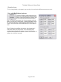
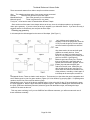
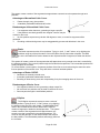
1
Technical Reference & Users Guide
Users Guide
Section 1 through Section 12
Technical Reference
Chapter 1 through Chapter 12
Copyright 2007 D. Broderick Software;
Auburn Michigan
Page 1 of 90
Technical Reference & Users Guide
Notice:
The software and documentation are protected by the copyright and patent laws of the United States of
America and other nations. It is a federal crime to make unauthorized copies or to alter the software in
any way.
License Agreement
This text is printed in various locations throughout the software program (hereafter called SHOPCAM or “the Software”) itself including the
Installation Program and About Box (found under the Help Menu).
IMPORTANT: Read this license agreement before removing the Software from its protective cover. Removing the Software will constitute
agreement to the conditions of this license. If you are not willing to be bound by the terms of this license agreement, promptly return all
materials to D. Broderick Software LLC (hereafter called DBS).
PROGRAM LICENSE AGREEMENT: SHOPCAM is provided under license from DBS. You assume responsibility for the selection of the
Software to achieve your intended results, and for its installation and subsequent use.
DBS grants to the buyer a nonexclusive license to use the Software and documentation that accompanies it in accordance with this
agreement. You may use the Software on one single workstation at a time (or as many workstations for which you have purchased
licenses). You may produce one (1) copy of the Software for backup purposes. You may transfer only the entire Software and license to
another party if the other party agrees to accept the terms and conditions of this Agreement and only after receiving written consent from
DBS. If you transfer the Software, you must at the same time either transfer all copies of the Software to the same party or destroy any
copies not transferred.You may not: copy, rent, distribute, sell, license or sublicense, or otherwise transfer the Software or this license, or
any program which is based on the Software or which incorporates the Software or a portion of the Software, to another party without written
consent from DBS.
This license is effective until terminated. You may terminate it at any time by returning the Software together with all copies and
documentation in any form to DBS. It will also terminate automatically and without notice from DBS if you fail to comply with any term or
condition of this agreement. You agree upon such termination to erase the software from any PCs on which it is installed and to destroy any
copy made by you for backup purposes.
Limited Warranty: THE SOFTWARE IS PROVIDED “AS IS”, WITHOUT WARRANTY OF ANY KIND, EITHER EXPRESSED OR IMPLIED,
INCLUDING BUT NOT LIMITED TO THE IMPLIED WARRANTIES OF MERCHANTABILITY AND FITNESS FOR A PARTICULAR
PURPOSE. The entire risk as to the quality and performance of the Software is with you, should the Software prove defective. You (and not
DBS or any authorized dealer) assume the entire cost of all necessary servicing and repair. Some states do not allow the exclusion of
implied warranties, so the above exclusion may not apply to you. The warranty gives you specific legal rights and you may also have other
rights, which vary from jurisdiction to jurisdiction. However, DBS ONLY warrants the media on which the software is furnished, to be free
from the defects in materials and workmanship under normal use for a period of (90) days from the date of delivery as evidenced by a copy
of your receipt.
Disclaimer:
D. Broderick Software LLC., your reseller, distributor, and/or dealer cannot be held responsible for the
use or misuse of this software. Computers, programmers, and users DO make mistakes. Thoroughly test
your tapes and analyze the output before running them. Furthermore, post-processors may not behave
the same way in all situations. When using new cycles or different methods than usual, check the tapes
even more carefully.
Duplication of this booklet, or any part thereof, is strictly prohibited. No part of this publication may be reproduced in any form without prior
written consent from D. Broderick Software LLC.
Information in this manual may be updated at any time without notice. D. Broderick Software LLC makes no warranties with respect to this
documentation. It is provided as a means of assistance only and D. Broderick Software LLC shall not be liable for any errors in its contents
or examples.
Copyright © 2003
SHOPCAM is a registered trademark of
D. Broderick Software LLC.
All Rights Reserved Worldwide
Revision date 02/28/2007
D. Broderick Software LLC
Auburn, MI 48611
Tel: 989-662-2623
Fax: 989-662-2640
www.shopcam.com
Page 2 of 90
Technical Reference & Users Guide
Section 1 Getting started................................................................................ 8
File Types ..................................................................................................................................8
Folders Or Directories ...............................................................................................................8
Learning To Use The System....................................................................................................8
The Screen Area .......................................................................................................................8
Layers........................................................................................................................................9
Coordinates ...............................................................................................................................9
Zero Degrees ......................................................................................................................................... 9
Five Steps of Part-Programming .............................................................................................10
Section 2 Operation Dialog .......................................................................... 11
How to perform an Operation ..................................................................................................11
Standard Operation Dialog ......................................................................................................12
Operation Dialog......................................................................................................................12
Standard parameter summary.................................................................................................12
Standard Lathe parameter summary.......................................................................................14
Determining The Tool Side .................................................................................................................. 15
Section 3 - Setup File, Tool & Material libraries ............................................. 15
The Setup File .........................................................................................................................15
Section 4 Making the Machine Code file...................................................... 17
Post Processors ......................................................................................................................17
Section 5 Picking geometry.......................................................................... 18
Pick Modes ..............................................................................................................................18
Picking with a Window ......................................................................................................................... 18
Picking By Selecting............................................................................................................................. 18
Picking via Chain.................................................................................................................................. 18
Pick lasso ............................................................................................................................................. 19
Pick last layer ....................................................................................................................................... 19
Select layer .......................................................................................................................................... 19
Query Geom information...................................................................................................................... 19
Section 6 Geometry Creation....................................................................... 20
CAD Files ................................................................................................................................20
Shopcam Geometry.................................................................................................................20
Quick Keys Chart ................................................................................................................................. 20
Page 3 of 90
Technical Reference & Users Guide
Patterns ...................................................................................................................................21
Lettering ..................................................................................................................................21
Section 7
Geometry Editing .........................................................................22
Trimming and Breaking ...........................................................................................................22
Trim Modal............................................................................................................................................ 22
Breaking ..................................................................................................................................23
Copying and Rotating ..............................................................................................................23
Section 8 Making Groups .............................................................................24
Cleaning up geometry .............................................................................................................25
Section 9 Approach methods.........................................................................26
NONE ................................................................................................................................................... 26
OFFSET................................................................................................................................................ 26
LEAD-IN................................................................................................................................................ 26
PREDRILL ............................................................................................................................................ 26
RAMP ................................................................................................................................................... 26
START POSITION................................................................................................................................ 27
Miscellaneous Commands..............................................................................27
GRAPHIC CURSOR TYPES...................................................................................................27
Section 10 The N/C Editor ..............................................................................28
Section 11 The Operation Manager................................................................29
Operation Manager Layout................................................................................................................... 29
Saving an Operation............................................................................................................................. 30
Section 12 Tool Library...................................................................................31
Saving and Deleting a Tool .....................................................................................................31
TECHNICAL REFERENCE Section ...............................................................32
Chapter 1 – The File menu .............................................................................33
The FILE Menu........................................................................................................................33
Chapter 2 – The Edit menu.............................................................................34
Undo the [U] key ................................................................................................................................ 34
Redo ..................................................................................................................................................... 34
Copy/Rotate.......................................................................................................................................... 34
Page 4 of 90
Technical Reference & Users Guide
Paste .................................................................................................................................................... 34
Delete the [Del]ete .............................................................................................................................. 34
Select ................................................................................................................................................... 34
Unselect All (Esc Key)......................................................................................................................... 34
Filter Selections.................................................................................................................................... 35
Move..................................................................................................................................................... 35
Mirror .................................................................................................................................................... 35
Rotate................................................................................................................................................... 35
Project Onto ......................................................................................................................................... 36
Trim and Break..................................................................................................................................... 36
Stretch .................................................................................................................................................. 37
Scale .................................................................................................................................................... 37
Chapter 3 – The VIEW menu ......................................................................... 38
The View Menu........................................................................................................................38
Window (W Key) ................................................................................................................................. 38
Center................................................................................................................................................... 38
Pan (S Key)......................................................................................................................................... 38
Grid Options ......................................................................................................................................... 38
View All (V Key) .................................................................................................................................. 38
Previous (J Key).................................................................................................................................. 38
Redraw (R Key)................................................................................................................................... 38
Zoom In / Enlarge area ........................................................................................................................ 38
Zoom Out / Shrink Area ....................................................................................................................... 38
Tool Bar................................................................................................................................................ 39
Layers................................................................................................................................................... 39
Labels (space bar) ............................................................................................................................... 39
Viewports ............................................................................................................................................. 39
Chapter 4 – The GEOM Menu ....................................................................... 40
The GEOM Menu ....................................................................................................................40
Point (P Key) ....................................................................................................................................... 40
Line (L Key)......................................................................................................................................... 41
Arc (A Key).......................................................................................................................................... 43
Circle (C Key)...................................................................................................................................... 43
Curve.................................................................................................................................................... 44
Pattern.................................................................................................................................................. 47
Series ................................................................................................................................................... 51
Page 5 of 90
Technical Reference & Users Guide
Lettering................................................................................................................................................ 52
Chapter 5 – The INFO menu ..........................................................................54
The INFO Menu.......................................................................................................................54
Setup File.............................................................................................................................................. 54
Material Library ..................................................................................................................................... 54
Tool Library........................................................................................................................................... 55
Current Files ......................................................................................................................................... 55
Default Directories ................................................................................................................................ 55
Default Editor command ....................................................................................................................... 56
Query Geom (Q Key)............................................................................................................................ 56
Edit Geom Attributes ............................................................................................................................ 56
Chapter 6 – The GROUP menu......................................................................58
The GROUP Menu ..................................................................................................................58
Outline .................................................................................................................................................. 58
Pocket................................................................................................................................................... 58
Face...................................................................................................................................................... 58
Holes..................................................................................................................................................... 59
Stock..................................................................................................................................................... 59
Boundary .............................................................................................................................................. 59
Chapter 7 – The OPERATION menu..............................................................60
The Operation Menu ...............................................................................................................60
Contour/2-Axis Mode Operations ......................................................................................................... 60
MILL mode operations.......................................................................................................................... 62
LATHE mode operations ...................................................................................................................... 66
WIRE-EDM mode operations ............................................................................................................... 68
PUNCH-PRESS mode operations........................................................................................................ 70
3D OPERS mode operations................................................................................................................ 72
Chapter 8 – The PROCESS menu .................................................................76
The PROCESS Menu..............................................................................................................76
Post-Process ........................................................................................................................................ 76
Resequence (See Operation Manager) ............................................................................................... 77
Edit/ DNC.............................................................................................................................................. 77
NC Control ............................................................................................................................................ 77
Chapter 9 – The Dimension menu..................................................................80
Page 6 of 90
Technical Reference & Users Guide
Dimensions menu...................................................................................................................80
Chapter 10 – The UTILITIES menu ............................................................... 84
The Utilities Menu....................................................................................................................84
Calculator ............................................................................................................................................. 84
Time Study ........................................................................................................................................... 84
LICENSING.......................................................................................................................................... 85
The Help Menu..................................................................................................................................... 85
Chapter 11 – Filter Mask & Tool side............................................................. 86
Chapter 12 – Tables and Charts .................................................................... 87
Tables and Charts ...................................................................................................................87
Hot Keys............................................................................................................................................... 87
Controlling Cutter Direction .................................................................................................................. 87
Main Operations and corresponding Material library opers. ................................................................ 88
Common surface speeds (In FPM) for various materials .................................................................... 88
Common feeds per flute/tooth (In FPM) for various tools. ................................................................... 90
Page 7 of 90
Technical Reference & Users Guide
Section 1 Getting started
You should have the system installed and licensed prior to starting. This manual will try to demonstrate most of
the features in the system. Shopcam is very flexible with several different ways to complete the same task. This
Users Guide is provided as an example of ways to use the system. Commands and Menus are covered in detail
in the Tech Ref Chapters of this Manual. If you are new to CAD and CAM, read Section 6 (Geometry Creation)
& Section 7 (Geometry Editing) before proceeding.
File Types
The following file types are used in Shopcam:
PRT
Shopcam part-program that contains a drawing or tool path
TAP
The ‘G-code’ text file for the machine control
MCH
The post-processor “Post”. Creates a tap (G-code) file from the part file
SET
Setup file; contains the post, tool & material libraries & default settings
TLB
Tool library. For storing tool information
MTL
Material library. For information about the material being machined
Most controls use their own extension for the G-code file. You may need to rename the .tap file for the control to
recognize it.
Folders Or Directories
The programs and files are organized in folders on the computer. Folders are also referred to ‘Directories &
subdirectories”. The system will be stored in a directory named "SHOPCAM". The files listed above, can be
accessed as:
C:\PROGRAM
C:\PROGRAM
C:\PROGRAM
C:\PROGRAM
C:\PROGRAM
C:\PROGRAM
FILES\DBS\SHOPCAM\PARTS\
FILES\DBS\SHOPCAM\TAPES\
FILES\DBS\SHOPCAM\POSTS\
FILES\DBS\SHOPCAM\MTRL\
FILES\DBS\SHOPCAM\TOOLS\
FILES\DBS\SHOPCAM\FONTS\
.PRT
.TAP
.MCH
.MTL
.TLB
.PRT
Learning To Use The System
The best way to learn is to try different things and experiment. The on-line
HELP is always available in the system by pointing at the command in question and hitting the [F1] key or
clicking the [?] icon and then the command in question.
The Screen Area
Command Menus – The command menus are the heart of the SHOPCAM system. All functions are performed
by selecting one of these items.
Command Icons – The command icons are Shortcuts located on the toolbar. The command icons perform
identical functions found in the Command Menus.
Page 8 of 90
Technical Reference & Users Guide
Operational Icons – When a command icon is selected, this area displays the icons that show the individual
choices within that command. For instance, the line icon will display all the commands for making lines.
Command Prompts – SHOPCAM displays messages on the Status Bar during each command. You should look
at this area. If you are unsure what to do, refer to this prompt. If the display is empty, this is an indication that no
function or command is active.
Pointer Location – The pointer
location is the current X, Y, and Z
position of your mouse.
Layers
If you are familiar with using CAD,
you should feel comfortable
working with layers. Layers are a
way to associate common
geometry. For instance, when you
group some geoms to create an
Outline, that Outline geometry
automatically goes on the next
available layer. It will be labeled
as Outline-X (where X is the next
open layer number). The same
rule holds true with Toolpaths. It
doesn’t change the base geoms
into a group, it creates new
geometry. When you want to
delete a group, the system needs
to know what layer that group is on. If you want to delete only a group or toolpath you should use ‘Select Layer’
or ‘Last Layer’ for your pick selection. If you use ‘Window’ to pick, you will also delete the base geometry
underneath it.
NOTE: use the space bar to toggle between displaying the labels or hiding them.
Coordinates
Cartesian Notation
The Cartesian coordinate system is a method of identifying any point in
space. It uses three axis, called X, Y, and Z, to map a grid of cubes. The
system identifies the three axis on the screen in the following manner:
X axis; The X axis is the horizontal axis Positive X is to the right,
negative to the left.
Y axis; The Y axis is the vertical axis. Positive Y is upward, negative is
downward.
Z The Z axis is perpendicular to the screen. A positive Z is toward you,
negative is away.
Zero Degrees
The 3 o'clock position is always considered to be a zero degree angle. All angles are reference from 3:00 or 0
degrees. This means that a horizontal line is a zero degree or a 180-degree line, depending upon its direction.
Two Dimensional Angles
A positive angle means a counter-clockwise rotation. For instance, a line going straight up on the screen is
ninety degrees, but one going toward the lower right is a negative angle. All angles are normalized by the system
Page 9 of 90
Technical Reference & Users Guide
(meaning a 270-degree angle is the same as a -90 degree angle. Angles are entered in decimal degrees. Enter
the value as you would any other number to enter decimal degrees (to specify a 22.5-degree angle, enter: 22.5
Units of measurement
Units of measurements refer to the intervals used to measure distances. Normally, coordinates are either in
inches or millimeters, however centimeters are also supported. The part-program is not in any particular unit
system. It consists of values that may represent inches or millimeters. In order for the system to generate a
tapefile for the NC/CNC machine, it must know what units are to be used. The info table contains a selection for
units. It is important that this is properly selected so that a tape can be generated correctly.
EXPRESSIONS AND VARIABLES
Expressions are permitted in any numeric response. These expressions are evaluated immediately and the
result is used in the answer. For complex problems, use the CALCULATOR.
Basic Operations
In expressions, the following operations are permitted:
[+]
[-]
[*]
[/]
[^]
Addition
Subtraction
Multiplication
Division
Power
(e.g.: 2+2 is 4)
(e.g.: 5-3 is 2)
(e.g.: 3*2 is 6)
(e.g.: 6/2 is 3)
(e.g.: 2^3 is 8)
Notice that the asterisk is used for multiplication. The letter [X] is never used for multiplication on computers
because that would cause confusion about a variable [X] and multiplication itself.
The slash [/] indicates division. Be careful not to use the backslash [\] by mistake.
Five Steps of Part-Programming
Although it is not required to name your part until you save the file, it is good practice to name your file as soon
as possible. You can give your part program any name but, it must follow the Windows standard for file naming
(refer to Windows documentation for more information). Your file will be saved with the extension .PRT.
Making a part-program to run your machine is done in five steps:
Setup
Load a setup file.
Geometry
Either import a DXF or create geometry.
Groups
Group geometry to perform operations on.
Operations
Use the operations to make toolpaths
Processing
Translates the partfile into a tapefile G-code
These steps are listed below, with more detailed descriptions.
No matter how many part programs you create with ShopCAM, you’ll find that these five basic steps are
repeated with each. As you gain experience with the system, you will find that these steps may be automated or
revisited multiple times during a programming session.
Note: Some toolpaths generation does not require groups. Engraving, Threading, Facemill to name a few.
These are covered in the Technical Reference Manual.
Setup
The SETUP file presets the parameters for a given machine i.e. post processor, tool library, and various defaults.
A part can be built without a SETUP file, but having a setup file loaded can make each session run faster. Most
users will have a setup file saved for each unique machine. The system will load the last used setup file for each
new part.
Geometry (aka Geoms)
Geometry is the collection of lines and arcs that compose the part. Geometry can be created from within the
system or imported from cad drawings via DXF files. See Section 6 (Creating and editing Geometry). This
Page 10 of 90
Technical Reference & Users Guide
manual may call geometries “Geoms”. There are basic geoms (the lines, points and arcs you create), group
geoms and toolpath geoms.
Groups
Groups are a collection of geometries that define pockets, contours, drill patterns, and any other machine-able
features. Once the base geometry has been built, you must group together geometries to be machined. When
you define a group, it is labeled and placed on the next open layer. The system then displays that layer number
in the label. For instance, a group labeled [Outline-15] is a group that will have the toolpath placed on the
outside of the shape and the group is on layer 15. See Section ?? (Grouping tips)
Operations
The operation is the heart of the CAM system. Machining operations act on Groups that have been built in the
previous step. After selecting an operation type the system will allow setting the machining parameters. These
parameters include selecting a tool, setting the step, depth, feed & speeds, CDC, coolant etc. When the
operation is created, it is labeled and placed on the next open layer. The system then displays that layer number
in the label. For instance, a finish path labeled [Toolpath-16] is a toolpath placed on layer 16. Some Shopcam
operations do not need a group. If the system needs a group, the dialog shown above will appear. See Section
?? (How to perform an Operation)
Processing
When the part-program has been completed and is correct on the screen, a tape can be made to run the CNC
machine. This is called "post processing or posting" the part. Post-processing translates the operations into the
numeric code that gets loaded into the CNC machine to make the part. Each machine has its own unique code;
there are thousands of different kinds of NC/CNC machines! The resultant tape is saved in a file that has the
same name as the part-program drawing. There are a couple ways to get the tap file to the machine. You can
use a DNC program (like Dostek DNC) to send the file to the control. You may save the file to a floppy disk.
Section 2 Operation Dialog
How to perform an Operation
Since most people want to make a part right
away, we put the operation section in the
beginning. You will want to read the following
Sections prior to making a part from scratch.
Shopcam will either need groups or can
generate a toolpath based on your
parameters.
Once an operation is generated, you may
choose to save all the information in the ‘Oper
Library’ for use on another part. We will cover
that in Section 11 ‘Operation Library’. For
now, we will cover operations the regular way.
Regardless of the operation, you will have an
‘Operation Parameters’ dialog box to use.
This dialog is presented when the [Set
Operation] button is hit.
NOTE: Foam Cutting and some 2-axis users
may not need to open the [Set Operation]
dialog. If the parameters are the same for each shape, just define them in the setup file (First operation Default)
button.
Page 11 of 90
Technical Reference & Users Guide
Standard Operation Dialog
Here is the standard operation dialog used for mill and 2-axis.
Operation Dialog
There are two ‘Operation Parameters’ dialog boxes, one for lathes and the standard one for all other modes.
Only the information that effects the operation you are working on can be modified.
Standard parameter summary
Here is a summary of the key parameters. Each parameter is described in the operation section of the
Technical Manual.
Step
Used for the XY step in roughing cycles
Default
or
From Group
Determines how the Z-axis values are applied. Default will use the ‘R-Plane Z’ and
‘Full Depth Z’ from Z0.0.
From Group will be the incremental distance from the group Z
R-Plane
The plane the Z axis rapids too. Usually .100 or .050
Tool Side
Which side to keep the cutter on.
CDC
Cutter diameter compensation; Usually causes a G41/G42 in the tape file
CDC Reg
CDC Register; Most posts use the tool number if set to 0.
Cap Radii
How the system treats sharp corners. Usually set to ‘Roll’.
Drill Cycle #
For canned drilling cycles; cycle 1 is system generated
Path Angle
To change the path angle on Zig Zag rough.
%Step Dev.
Allow the step to deviate to equalize passes
Max Cusp
Adjusts the resolution of the steps of 3D operations
Calculated
If a material library is loaded, will figure RPM & feeds
From Tools
Loads the feeds and RPM from the tool library
From User
Allows you to set your own RPM & Feeds
Approach Methods
Approach is how the tool gets on and off the part. A summary of
the currently approach setting is displayed to the right of the
button. All the approach methods are defined in the ‘Approach
methods’ Section.
Tool Button
The tool button will bring up the tool
dialog. From there you can load a tool
from the library, use a tool that you
already used in the current part or define a
new tool. A summary of the current tool is
displayed. The tool dialog is defined in detail in Section ??
Oper Comment
You may add a description of the operation. This will show up in the “Operation Manager” dialog summary and
in the report.
Page 12 of 90
Technical Reference & Users Guide
Operation Image
This is a image based on the operation you are using. It shows how the different parameters are used.
Post mods (Modifications) and more
The post mod dialog contains parameters that
may or may not be used by the post processor.
If there are special instructions for a post, it will
be in a txt file, with the same filename as the
post. For instance, as a general rule, if a post supports a 4th axis
table, it will use Cycl(?) as the radius. Offset/1 and Offset/2 could
be used on an old lathe or maybe something totally different. The
‘Power’ field is often used on Wire EDM and as a Fixture offset on
mills.
The ‘At Posting time modifiers’ do just that, they change the GCode output when you post process. These ‘At Posting time
modifiers’ should be used with caution. It’s not obvious on the
screen that the toolpath will be shifted or scaled. You are better off
shifting with the ‘Move’ command.
Page 13 of 90
Technical Reference & Users Guide
Standard Lathe parameter summary
Here is a pic of the
standard lathe
parameter box. The
graphic is not of the
part you are
programming, but
shows how the values
are used.
Below is a summary
of the key turning
parameters. Each
parameter is
described in the
operation section of
the Technical Manual.
Each operation will
gray out the boxes it
does not need. A
generic picture will
show how the most
important parameters
will be used.
Step
Used for the XZ step in profile cycles
Extra Stock
Additional stock to leave on straight OD cuts
R-Plane
Where the Z axis positions for a pass; Absolute value.
Tool Side
Side to keep the cutter on. Usually right for OD left for ID
CDC
Not usually used on a lathe
Path Angle
The ‘rough Turn’ path angle usually=0 or 90 for facing.
%Step Dev.
Allow the step to deviate to equalize passes
Calculated
If a material library is loaded, will figure RPM & feed
From Tools
Loads the feed and RPM from the tool library
From User
Allows you to set your own RPM & Feed
Page 14 of 90
Technical Reference & Users Guide
Determining The Tool Side
Determining the tool side is very easy. Imagine walking along
the geometry you wish to cut. Is the tool to the right or left of
that geometry? In the previous FINISH example, the Tool
Side (Left of Geom) performed a Climb Cut. Though the
OUTLINE was defined in the opposite direction, the computer
knew on which side and in which direction to cut from the
Group Type and the Tool Side.
Cutter Compensation is also a factor. It can be performed
either by computer or machine tool. In determining the
preferred method, consider the following:
Allow the computer to compensate for all roughing cycles.
Specify the tool side, tool width (and corner radius if any) and
set CDC to OFF, which disables the machine compensation.
Allow the computer to compensate for most finishing cycles (Mill and Wire). Enable CDC on the machine and
set the machine compensation to correct for variations due to wear and cutting conditions. You do not want to
double compensate by having Shopcam offset the cutter and the machine do the same.
Section 3 - Setup File, Tool & Material libraries
The Setup File
A Setup file allows you to set and
save preferences. Normally you
would have a setup file defined for
each unique machine tool. Since the
machine (Post-processor) is the most
important part, You may want to ‘save
as’ a filename that incorporates the
machine and control. Change it from
default.set so it doesn’t get stepped
on incase you ever reinstall.
Page 15 of 90
Technical Reference & Users Guide
Use
the
[Bro
wse]
butto
ns to
chan
ge
the
file
or
the
[Clea
r]
butto
n if
you
don’t
want
a
librar
y file.
Setup File
The setup file being used.
Post Processor:
The post-processor to be used.
Material Library:
The material library to be loaded (optional)
Tool Library:
The tool library to be loaded (optional)
Inch or Metric:
This is for the post processor output. Most, but not all, posts support metric output.
If you are in metric mode and the output is about 25 times to small, metric isn’t
supported. Contact your dealer to have metric output added. If you normally work
in inch and receive a metric CAD file, use the [Scale] command to make your
geometry inches.
Radius value or
Diameter value
In Lathe mode, it determines whether the X axis values you enter are diameters or
radial.
Decimal Display
How many places to the right of the decimal do you want to display on the screen.
Most people set this to four. A WEDM user may prefer 5 while a router user may
only need 2, This has no effect on accuracy.
Forgivance
Normally this is set to the minimum move of your machine or .001 for a mill or lathe.
It will also help with chaining. This has no effect on accuracy
Toolchange X
Toolchange Y
and
Auto 1st Toolchange
This serves two purposes. It is used to ensure compatibility with older posts and it
makes sure the 1st move squares properly on a 3 axis machine. These values
should be set to coordinates off the table. Check the ‘Auto 1st Toolchange’ and
program a simple part. If the coordinates on the first couple moves are correct,
leave it checked. If these coordinates are output at every Toolchange, uncheck it.
Prior
to
savin
ga
setup file, set the machine mode on the ‘Command Menu’ at the top of the screen. The mode is located
between the ‘Group’ and ‘Operation’ menus.
Contour mode is the same as 2-axis mode. If you use a Foam cutter, Waterjet, Plasma, Cutting torch or any
two axis, select Contour
Setup File parameter summary
How you set the system defaults will depend on what you are writing programs for. Below is a list of the key
parameters and suggested settings.
First Operation Default
With each setup file you can and should set the default operation parameters. This is especially important if
you don’t use a tool library. 2-Axis users (foam cutters, water jet, and burning tables) should set the these
parameters as you do on all shapes. That is usually tool ID number and changer set to ‘1’ and the tool width set
to ‘0’. Also, set the tool to round and set a federate to something other than ‘0’.
.
Page 16 of 90
Technical Reference & Users Guide
Section 4 Making the Machine Code file
After the toolpaths are defined, you are ready
to translate the part program into a file your
machine can use. This is called ‘post
processing’ or ‘posting’. There are two ways
to post process, with the menus or the icons.
With post processing you may chose a
couple different ways to visualize the posting.
NC Codes only:
Just makes the machine code file.
Draw 2D Animation: Fills the screen with different color then blackens where the tool visits.
Draw Tool Chain: Snakes an outline trail, of the tool, as it travels around the part.
3D Simulation: Runs the optional 3D modeling program. Mill & Turning only
Post Processors
Every machine requires its own unique codes to cut a part. There is a standard ‘RS-274D’, but for some reason,
many Control Manufactures rely on their own modified version. Plus some Machinist just prefer to see the
machine code a certain way.
The program that writes the machine code file is called a ‘post’ or ‘post processor’ and has a .mch extension.
The machine code file it creates is called a tapefile with a .tap extension. The system will save the part prior to
posting. If an error message or warning appears during posting, it is usually generated by the post program.
Refer to the post processor’s instructions for an explanation of the message. The instructions will have the same
name as the post with a .txt extension.
Page 17 of 90
Technical Reference & Users Guide
Section 5 Picking geometry
Pick Modes
The pick methods are used to select single
or multiple geometry items for any
command that needs geometry. Almost
everything you do, will need to pick
something first.
You need to pick geometry to copy, delete,
group, edit, trim, rotate, stretch and create
geoms based on other geoms.
Picking with a Window
To use a window to pick items, only the items that are ENTIRELY INSIDE of the window
will be selected. This means both ends of a line must be enclosed for the line to be
picked.
To use a window to select items, first indicate one corner. Any of the four corners of the
window can be selected. When asked to indicate the other corner, it must be the diagonally opposed corner.
Here, the cursor changes to a WINDOW to indicate the area enclosed.
Exception: When using a window to STRETCH items (via the EDIT MENU) Lines lying entirely inside of the
window will be moved.
Picking By Selecting
When picking items with the SELECT method, continue picking single
geometry items. When you have picked all you need, click on the
[done] button in the dialog box.
Picking via Chain
Picking with a chain is used when there is contiguous (connected end to end) geometry. When selecting items
via CHAIN, the system will ask you for the first item. After picking, the system may ask for a "direction". If the
system can chain in more than one direction, the system will ask for a desired direction. This will place a bulls
eye at the position where it could last determine. The programmer cannot indicate a direction by digitizing a
location in the desired direction. The programmer must pick an item that has an endpoint at the center of the
bulls eye.
The system can ask for a direction in any of the following:
There is a fork in the geometry, where three or more items meet
at a common point.
A chosen a start point from where the chain could proceed in
either of two or more directions.
There is a Z-only line hidden in the current view.
There are two or more identical geometry items that are "on
top" of one another.
The chain will be complete under these two conditions:
The chain has returned to the start point.
No more common endpoints can be found.
Page 18 of 90
Technical Reference & Users Guide
Select chain is the preferred method for creating a group. The reason to always use the chain to create a group
is that it guarantees the group is mathematically correct prior to generating an operation with it. After entering
one chain, the system will ask for another chain. If selected, the new chain will be appended to the first. This can
be repeated any number of times.
Pick lasso
The lasso is similar to window except you will create an irregular pick area by digitizing points around the
selected items. Use this when you have to ‘snake’ around geometry you don’t want to include in the picked
items. The start and end points must overlap to close the lasso. Once the lasso is complete, select the icon
again to execute the pick. All other Pick Windows terms apply.
Pick last layer
Pick last layer will select the last layer used that contains information. By clicking on the icon
again, it will select the next to the last layer and so on. This makes it easy to delete completed
layers.
Select layer
Select layer icon will ask for the layer number to select.
Query Geom information
The Query command is used to gather information about
geometry. The Query command can be selected from the
info menu or with the [Q] key. After selecting a geometry
item, the Query dialog box will appear showing the geometry
data.
Two temporary filter buttons are located on the Query dialog
box.
1. The [Selection Filter] for masking certain types of
geometry
2. The [Layer Mask] for selecting specific layer.
The coordinates for the selected geometry will appear in the
dialog box. If a line is selected, the angle will be displayed
with the start and end coordinates. With an arc or circle, the
radius, start and end are displayed.
To view attributes of the selected geom, click on the [View
Attribute] button. The ‘Attributes for display only’ dialog box
will appear. Refer Section 11 of the Technical Reference
manual for Attribute Table information.
In lathe mode a check box for displaying the X axis as a
radius or a diameter.
Page 19 of 90
Technical Reference & Users Guide
Section 6 Geometry Creation
There are two ways to get geometry into the system. You can import/merge a CAD file from another package,
or create geometry in Shopcam
CAD Files
To merge a cad file, go to the [Files] menu then [Import]. The system recognizes two different CAD formats,
DXF and IGES. We use the AutoCAD standard DXF format as a baseline. A couple notes about CAD files:
Avoid CAD files that consist of surfacing or a wire frame. Use basic geometry.
If the DXF won’t read, use the [Explode] feature of your CAD software.
Shopcam Geometry
There are three ways to create geometry in the system.
Basic [Geometry] commands to create a point, line, arc or circle.
[Edit} commands (copying or mirroring) to create more geoms.
[Patterns] commands to create rectangles, ellipsis, gear, hole grids etc.
There are three ways to access the basic geometry commands.
With the command icons
Using the [Geometry] menu on the main menu.
With the shortcut keys listed below.
Quick Keys Chart
key
Description
key
A
Arc though 3 positions
S
Pan or Slide the display
B
Break two geoms at the
intersection
U
Undo Last Command
C
Create a Circle
V
View All the geoms
F
Fillet on two geoms
W
View Window
I
Invert or reverse an Arc
X
Trim Both
J
View previous (jump back)Z
Set Z Depth
L
Create a Line
F1
Help
O
Set a temporary Origin
F2
Select an End Point
P
Create a Point
F3
Select a Mid or Center Point
Q
Query a geom for
information
F4
Select an Intersect Point
R
Redraw or Refresh the
screen
F7
Rotates Sprite CCW 5°
ESC
Abort/Cancel
F8
Rotates Sprite CW 5°
↑
Speeds Posting Graphic ←
↓
Slows Posting Graphic
→
Description
Rotates Sprite CCW 1°
Rotates Sprite CW 1°
With the four basic geometry types (Point, Line, Arc and Circle), the ‘Operation Icons’ will appear on the left of
the screen allowing you to select the command you need.
For a complete list of the basic geometry commands, see the ‘Technical Reference Manual’
Page 20 of 90
Technical Reference & Users Guide
Patterns
Shopcam has several patterns available. A pattern may be as simple as a square or rectangle or a complex
pattern like a gear or circular cam. When a pattern is created, it will be a series of individual geometries.
For a complete list of pattern commands, see the ‘Technical Reference Manual’
Lettering
This command creates the simple
geometry that representing the
alphabet. Do not confuse this with
engraving, which will actually
generate a tool path. Use lettering
for raised or recessed shapes.
Page 21 of 90
Technical Reference & Users Guide
You need to group the shapes then perform a operation on the groups. Only select a font file that starts with
‘Font_Outline’. Fill out all fields indicated and click on the OK button to execute the command. All fields will be
filled with system defaults except for the TEXT. Hit the [Make Tool path] button to create the geometry.
Some fonts may not include all of the upper and lower case letters of symbols found on a standard keyboard. If
the item is not available in the font then it will not appear when the command is executed. The part files contain
various fonts
Section 7
Geometry Editing
Geometry editing may be used to create more geometry via copy or mirror. You may also edit geom by trimming
it or breaking it.
Trimming and Breaking
After creating geometry, you may have to trim it to
a different geom to form a sharp corner. You may
have to break it to select a start point for a group.
The most common trim command is [Trim Both].
The quick key for ‘trim both’ is the ‘X’ key
When trimming, the system will look at where you
digitize to determine what you want to keep and
what gets trimmed off. You will select the geometry
to keep.
When breaking two geometries, it is not that critical
where you pick because the all the geometry will
remain. When you break two geometries, nothing
appears to happen, but you will have four
geometries instead of two.
This circle example is often
confusing. The circle doesn’t
appear to trim on the first trim.
Notice in the two examples on
the left. Notice which part of the
geometry gets trimmed off and
what geometry remains.
Trim Modal
This instruction is used to trim off geometry items where they
intersect another item. The system will ask for the trimming item
first, then the items to be trimmed off. Unlike the TRIM BOTH
instruction, this one requires that you pick the geometry items along the portion to be trimmed
portion to be retained.
Page 22 of 90
off, not the
Technical Reference & Users Guide
In this example, the vertical lines must be trimmed at the horizontal line as shown. Using the TRIM MODAL
command, the horizontal line is selected as the trimming item. The vertical lines are selected as the items to be
trimmed. They must be picked along their portion that lies below the horizontal line, as that is the portion to be
discarded.
Breaking
The most common use for breaking a geom is to specify a starting point for a group. Take a simple rectangle
for instance. If you group a rectangle without breaking one of the four lines, the group will start on one of the
corners. This may or may not be what you want. If you want to sweep onto the shape with a arc, the start and
end geometries must form a 180 degree included angle. The easiest way to accomplish this is by breaking a line
or circle. Another common use for breaking a geom is to specify a glue stop for a Wire EDM.
Copying and Rotating
With the copy command, you must select the items to copy then
specify the start point and the end point. You may think of the start
point as the ‘Reference Point or Anchor point’ and the end point as
the ‘Destination Point’. If the start and end points are the same, the
system assumes you want to rotate and will display a dialog box to
enter degrees.
In this example, we have to rotate the engraved toolpath 15 degs
counterclockwise.
After invoking the copy command, we are present with the pick mode
dialog. Since we know Toolpath-1 is the last layer, we can select
‘Last Layer’. The Toolpath will turn blue and we can then hit the [OK]
button. At this point, a dialog box will appear with the start and end
fields. In this example we simply want to rotate the toolpath around
the center of the shape. Rather than entering the center point, we can snap to the center of the arc. After the
[OK] is hit, the dialog
for ‘degrees’ will
appear.
If [Digitize] is
selected, the picked
geometry will turn into
a sprite that can be
moved with the
mouse. The F7 and
F8 keys will rotate the
sprite five degrees,
CW and CCW
respectively. The
right and left arrow
will rotate it one
degree.
Page 23 of 90
Technical Reference & Users Guide
Section 8 Making Groups
We have touched on groups earlier in this manual. Since groups are critical to generating operations and a bad
group will cause an error message when trying to generate an operation, we will spend some time on them.
The type of group is important when the system performs an operation on a group. If a group is a closed contour
that defines the outside of a part, it should be called an OUTLINE. If a closed contour defines an internal form, it
should be called a POCKET. If it is an open shape, it should be a BOUNDARY or FACE. Collections of circles
and/or points that are to be drilled are called HOLES.
The group type determines on which side of the geometry the tool will cut. To profile rough the outside of a part,
group it as an OUTLINE. To rough out the inside of a part, group it as a POCKET. With a BOUNDARY, the tool
can cut on either side of the contour depending upon the value in the tool SIDE. With Pockets and Outlines, the
group must start and end at the same place. It needs to be a closed shape.
Some operations can only be performed with certain groups:
MODE
OPERATION
GROUP
MILL
ZIG ZAG HOG
POCKET
MILL
PLUNGE ROUGH
POCKET
MILL
DRILL CYCLES
HOLES
LATHE
ROUGH TURN
BOUNDARY
LATHE
PROFILE
BOUNDARY
LATHE
GROOVE
BOUNDARY
LATHE
FINISH
BOUNDARY
WIRE EDM
MULTIPLE PASS
POCKET or OUTLINE
3D OPERS
MULT Z RUFF
POCKET
3D OPER
SWARF
BOUNDARY
In the examples below, we want to machine a raised letter ‘B’. The 1st group we created is Pocket-1 around the
box. Then we do the top inside of the ‘B’ (Pocket-2) and the bottom inside (Pocket-3). The outside of ‘B’ is
grouped as an outline and is automatically placed on layer 4 (Outline-4).
When selecting one of the group types, the pick icons will appear on the left. Any of the pick modes may be
used; it is good practice to always use chain to create a group. If you use chain to create a group, it guarantees
the group to mathematically correct prior to generating an operation with it. A group has to be correct for the
path processor algorithms to calculate the passes and offsets. If a chain stops for no apparent reason, you
shouldn’t just click to get the chain going again.
When a chain stops, and displays a bull’s-eye, there is always a reason. There is something in the geometry
causing it. This is especially true if you receive CAD files from outside sources.
Page 24 of 90
Technical Reference & Users Guide
There are several reasons for a chain to stop for no obvious reason:
Gap; The endpoint and start point of two geoms are not connected
Overlap;
There are two geoms on top of each other
Mismatched layer;
Part of the geometry is on a different layer
Miniscule geom;
There is a geom that is very small
Z only line; A line has the same XY start/end but different Z depth
Since each one of the cases is not always obvious to the eye, there is a simple procedure to go through to
clean up the geometry. If you are curious as to why it stopped, try to chain after each fix. If you don’t care why it
stopped, assume it could be any one and just do all the steps.
Cleaning up geometry
In this example the chain stopped on the corner of this shape. (See Figure 1)
Let’s eliminate each reason for the
stoppage. First hit the [OK] button, then the
‘U’ key to undo the group. Over the years,
we have found this procedure to work the
best.
Gap; these tend to be rare and with good
graphics are usually obvious. Since
trimming is so easy, let’s eliminate it first.
Hit the ‘X’ key (quick key for trim both) and
pick line 1 and arc 2 (see figure 2)
Miniscule geom and Z only line; The best
thing to do with this is just delete with a
window around the area it stopped. Hit the
[Delete] key and select the [Box] pick
method on the left icons. Make sure you
don’t include all of the arc (see figure 3).
Since these two reasons cause about 70%
of the problems, I would try a chain again. If
it still stops at the same point, continue to
C.
Overlapped Geoms; These are hard to catch and rare. The best way is to just delete the geom it stopped at and
see if another geom or part of a geom remains. (Figure 4) If a line remains, try grouping again. If a partial geoms
remains, trim the line to the next line and then group.
Mismatched Layers; If none of the above methods worked, it has to be this. Hit the ‘Q’ key and select the geom
the chain stopped at. Note the layer and select the adjacent geom. When the oddball geom is determined, use
the [Info] [Edit Geom Attributes] command, select the geom with the different layer, and change the layer
number to the same as the rest.
This may seem confusing, but if you use CAD files from different customers, you will encounter each one of
these conditions eventually.
Page 25 of 90
Technical Reference & Users Guide
Section 9 Approach methods
The approach is how you get on and off the part. If starting on an arc, you can not apply CDC without a line
move. It is a good idea to use an approach on finish operations where you would use a CDC offset. The
approach and pull-off is not used by lathe, drill cycle, or 3D operations.
NONE
None approach indicates that the tool should move directly into tangency with the finish work piece before
beginning its machining path.
OFFSET
Offset approach method to cause the tool to move to a position that is the CLEARANCE distance away from the
finish work piece, and then feed perpendicular to the 1st move. Upon completion, the tool will move away from
the finish work piece until it is the CLEARANCE distance away before retracting. On an open group (boundary)
the offset will extend the 1st move by the clearance amount.
LEAD-IN
The Lead-In method causes one of three methods to be used, depending upon the location of the start point on
the group to be machined:
If the start point is along a tangent move, then a ninety-degree arc will be constructed tangent to the start point,
and used to "wipe onto" the work piece. Another ninety-degree arc will be added to the end of the tool path to
"wipe off". These arcs will have a radius of the ‘Arc Rad’.
If the start point is at an inside corner, then the same approach is used as OFFSET. If methods two or three are
expected but generate gouging (tool interference) then this method will be invoked instead.
If the start point is at an outside corner and CAP RADII are enabled then the tool path will begin off the part by
extending the start point of the first geometry item back by the TAIL LENGTH. The tool path will also be
extended past its end point by lengthening the last geometry item by the TAIL LENGTH. This allows the tool to
"wipe on" and "wipe off" the work piece.
PREDRILL
A group of circles will be constructed on the next open layer, and labeled "HOLES". A hole/circle will be
generated at each plunge point where the approach is started. This is useful for selecting with a subsequent
DRILL operation to pre-drill the plunge points. If this is done, the DRILL operation needs to be resequenced
to precede the machining operation.
RAMP
Ramp is commonly used for pocket roughing, when using PROFILE ROUGH, ZIGZAG HOG, or MULT-Z
ROUGH. The system will attempt to create a three-axis ramp cut into the work from the R-PLANE Z. The ‘XY
length’ of this plunge is specified as RAMP LENGTH. The system may need to shorten the RAMP LENGTH in
order to fit into the removable material boundary.
Page 26 of 90
Technical Reference & Users Guide
START POSITION
Start Position is used when a start hole is already drilled. The system prompts for the start positions. Digitize or
enter the coordinates of all of the permissible locations. The Z values will be ignored. Whenever the system
needs to plunge the tool into the work, it will select the nearest start point as the plunge position. However, the
system does NOT validate the move from that plunge point to the pickup position on the contour. Thus, if not
entered a start position that can be clear of the work near the start of a contour, the system may need to make a
long cut from the plunge point to get to the contour. This move may interfere with the finish contour, so be sure to
visually check for such conditions before post-processing.
The parameters listed below are used with the approach commands.
Clearance
Clearance is used as a safe startup distance from the finish work piece. When approaching the work or retracting
the tool, the system will attempt to move the tool to a position that is this distance away from the contour. This
has to be entered with an OFFSET approach. This is usually at least half the tool width.
Arc Radius
If LEAD-IN is chosen, this is used to specify the radius of the arcs.
Ramp Length
When the RAMP approach method is used, the system will make the three-axis moves a length (in the XY plane)
of RAMP LENGTH. If this cannot be accomplished, the system will make the moves as long as it can without
gouging the work piece.
Miscellaneous Commands
GRAPHIC CURSOR TYPES
The plus shape indicates an XY or Z must be entered or digitized on the screen.
Crosshair Cursors
The X shape indicates that a “pick” of the geometry can be chosen.
Round Cursor [F2]
The round cursor indicates an ENDPOINT pick mode is enabled.
Box Cursor [F3]
The box cursor indicates a CENTER-POINT pick mode is enabled.
Intersection CURSOR [F4]
1
The
The intersection cursor indicates sequential selections of two geoms whose intersection will be
digitized. After the 1st geometry is selected, the cursor changes to a ‘2’.
+s shape indicates that the filter mask is active
Page 27 of 90
Technical Reference & Users Guide
Sprite Cursor
The sprite cursor is the actual shape of all the geometry that is digitize when using the move, copy, rotate,
mirror, merge or scale commands
Section 10 The N/C Editor
A 3rd party editor is provided with Shopcam. It is the same editor supplied with the Dostek DNC package we
recommend. For help on this editor, select the help menu from the editor.
Almost any editor may be used. If you have a text editor you would prefer, you can change it. Select [Info] then
[DNC Command]. Use the [Browse] and select your editor and hit [OK].
Page 28 of 90
Technical Reference & Users Guide
Section 11 The Operation Manager
The Operation Manager is a dialog box with a list of all the operations in
the current part and a list of operations from a library. This feature will allow
you to save and recall all the information required to generate or regenerate
a Toolpath.
There are two operation libraries. “Lathe.opers” and “Mill.opers”. These are
located in the default install directory (C:\Program Files\DBS\Shopcam).
Lathe.opers is used for Turning/Lathe and Mill.opers is used for everything
else.
The first time you save an operation, this file is created.
This dialog is used for three purposes. Saving, retrieving or editing an
operation.
The Operation Manager selection is located at the bottom of the Operation
menu
Operation Manager Layout
The operation manager
dialog consist of three
main areas:
Operation Library:
This is a list of the
operations stored in the
operation library file.
Control buttons are
located at the bottom of
this list. This is the list
on the left
Current operation list:
This is a list of the
operations in the
current part. This is on
the right.
Operation Summary:
This is summary of the
most important
parameters of the
selected operation. This
is at the bottom.
Page 29 of 90
Technical Reference & Users Guide
Saving an Operation
With the operation
dialog open, one
operation is always
active. The operation
summary area will tell
you which operation is
currently active. You may click on an operation
from the library list or from the current part file
list and make it active. Once active, you may
edit it and save it to the library.
Use the up arrow [Save] key to move the active
operation into the library file.
If the active operation was selected from the
current part list, it will be appended to the end
of the library list and the file saved. If the active
operation was selected from the library list, you
will be asked to replace or add to the end of the
library list. The file is saved automatically.
Building your own custom library consist of
either editing an exist operation from the library
and adding to the end of the list or selecting a
operation from a part and adding to the library.
Using an operation from the library
To generate a operation in Shopcam, you can do it the traditional way by selecting a operation from the menu or
from the operation manager. Select ‘Operation Manager’ from the bottom of the operation menu. When the
operation dialog opens, select a operation from either the operation library list or from the current part file list.
Once selected click on the ‘use oper’ button. If the operation requires a group the ‘Operation Inputs’ dialog will
appear and allow you to select some groups and hit ‘Make Toolpath’ to create the toolpath. Operation that don’t
require groups (Engraving, facemill, threading etc), will go directly into their dialog box.
Editing an operation
Editing a operation is pretty straight forward. After opening the operation manager, select an operation from
either list, make the changes and save it. Part programs generated with the new version of Shopcam will contain
all the information needed to regenerate a toolpath or save to the library.
If you are editing a operation from the current part list, and want the toolpath to reflect the changes, you will need
to hit the [Make Toolpath] button. If the operation requires a group the ‘Operation Inputs’ dialog will appear and
allow you to select some groups and hit ‘Make Toolpath’ to create the toolpath. The
layers that originally generated the toolpath will be checked. Operation that don’t require groups (Engraving,
facemill, threading etc), will go directly into their dialog box. You can see that it is important not to delete group
layers if you might want to make changes to an existing toolpath. If you are editing a operation to save in the
library, make sure to use the ‘up arrow’ to save your changes to the library.
Page 30 of 90
Technical Reference & Users Guide
Section 12 Tool Library
Using the new tool library
dialog is much like using the
operation dialog. There are
two list, the current library and
the tools used in the part
program. The new tool library
dialog has been expanded to
included a picture, default
speeds and feeds, and a spot
for tool comments.
Saving and Deleting a
Tool
Use the up arrow to save the
active tool into the library. You
may select a tool from the
current tool list. This is a list of
the tools in the opened part
You may also select an
existing tool from the tool
library list. You may edit these
values prior to saving them.
Use the [Save as] button to
save the existing tool library
under a different name.
To delete a tool from the
library, highlight the tool and
hit the delete button.
The ID number or ‘Tool ID’ is
simply a numbered list of the
tools in the library. Older
revision called this the ‘Tool No’. Since the ‘Tool Changer No’ is the actual number sent to the postprocessor and
output as a T-word, it was confusing.
If a Tool ID number exist, you will be asked to replace or add. .
Tool library list: This is a list of the tools in t he currently loaded tool library
Partfile Tool list: This is a list of the tools in the current part program
Tooling parameters: This is where you enter information regarding the tool.
Tool Picture: This is a generic picture to help with tool types and parameters.
Speeds & Feeds: Theses are the default speeds and feeds for the tool.
Page 31 of 90
Technical Reference & Users Guide
TECHNICAL REFERENCE Section
This section of the manual will step through each menu and command.
Page 32 of 90
Technical Reference & Users Guide
Chapter 1 – The File menu
The FILE Menu
The File menu will be familiar to most people who have used Windows programs.
New
Use the NEW menu selection to start a new part-program. Load or create a Setup file any time new part
is started. Setup Files can make programming a part much easier.
Open
Use the OPEN menu selection to open an existing part file. The Part File menu will appear. Open a file
by clicking on the desired part file, and then click the open button. When an existing part file is loaded,
the setup file, tool library, material library and post-processor will also be loaded.
Save
When SAVE is selected from the FILE menu, the file will be updated to the current state of the partprogram.
Save as
When SAVE AS is selected from the FILE menu, the system will for a filename. A identical file will be created.
Import
The IMPORT menu selection will merge an existing file or part of an existing file with the current part-program.
When merging CAD files is sure the file contains only individual geometry (points, lines, arc, or circles). If your
geometry is grouped as a single entity (polyline or spline), the geometry must be ‘exploded’ or ungroup
from within the cad program before merging into Shopcam.
The following types of files can be imported: CAD files (*.dxf), CAD files (*.igs).
DXF FILE
The DXF file format is an accepted standard used by many CAD and CAM systems. All points, lines, arcs and
circles will be read from the DXF file.
IGES FILE
All points, lines, arcs and circles from the IGES file will be read. Use caution when picking, chaining, and editing
the geometry from an IGES file. IGES files often contain multiple occurrences of geometry.
Export
The EXPORT menu will ask for a file name. Shopcam support the DXF format, which is standard used by many
CAD and CAM system
Print
To send a file to your printer selects print. The print dialogue box will appear with information showing
your default printer. Click on the OK button to send the information to the printer.
Exit
Use this to exit the system. . If any changes have been made to the part since it was loaded, the system will ask
if wish to save the part and the Setup is changed, you system will ask to save it.
Page 33 of 90
Technical Reference & Users Guide
Chapter 2 – The Edit menu
The EDIT menu changes the geometry directly. The edit menu should not be
used to change a displayed view, the VIEW menu has selections for that
function.
Undo the [U] key
The UNDO key restores the part-program to the way it was before the
last instruction was modified. If the last instruction created a group, this
deletes the group. The UNDO instruction may be repeated multiple times –
continually deleting instructions previously performed. This function may be
repeated up to 9 times.
Redo
The UNDO instruction can be undone by using the REDO instruction.
This instruction is performed when an UNDO command was executed by
mistake. It “undoes” the UNDO command. The REDO command can be
repeated up to 9 times.
Copy/Rotate
The copy/rotate instruction copies and or rotates selected items while retaining the original items in the
part drawing. (See Move) The COPY instruction is used to duplicate selected geometry items to one or more
new locations. See the ‘Shopcam Users Guide’ for a detailed explanation.
Paste
The PASTE function retrieves geometry stored in the clipboard and allows placement at a specific location within
the part drawing.
Delete the [Del]ete
The delete selections allow removal of selected geometry items from the part-program. Group and toolpath
layers may be deleted
Select
Choosing SELECT from the EDIT menu will allow picking items. When a command is selected, it will be
performed on these selected items, (i.e. DELETE, COPY, GROUP, MOVE, etc.). If the DELETE key is hit, all
picked geoms will be deleted.
Unselect All (Esc Key)
Choosing UNSELECT ALL from the Edit menu will undo the picked items.
Page 34 of 90
Technical Reference & Users Guide
Filter Selections
FILTER SELECTIONS identifies entities that ‘are
allowed to be selected’. It determines what type
of geometry can be selected. These entities
include Points, Lines, Arcs, Circles, Dimensions, and
Text. The search can be narrowed to only groups, tool
paths or geometry on a single Z level. Keep in mind, a
geometry can have two different attributes associated
with it. It could be a circle and a group.
When the filter is active, the cursor will have a ‘S’ next to
it.
Note: If unable to select an item, check the selection filter. Make sure you turn
it off. The Cursor will have a ‘S’ next to it. Hit the [E] to enable all items to be
selected.
Move
The MOVE instruction is used to move selected geometry items from their present location to a new location. .
See the ‘Shopcam Users Guide’ for a detailed explanation of this command.
Mirror
This instruction is used to make a mirror image of selected
geometry entities. If a tool path is mirrored, then any CDC
(cutter compensation) will also be mirrored. This means that a
CDC LEFT will be mirrored to become CDC RIGHT and vice
versa. The system will ask to mirror the geometry on the XAxis (mirror horizontal), on the Y-Axis (mirror vertical), or
around specified line. If either of the first two are chosen, the
mirroring occurs around the origin. If you select to mirror over
a line, the system will ask to select the line. The entities may
also be duplicated, meaning the originally selected entities
can be kept in place and a duplicate ”mirrored”..
Rotate
The ROTATE command allows you to rotate select
geometry from the XY plane. When finished selecting, click
the DONE button, and a Rotation Axis dialogue box will
appear. You have a choice of rotation on the X-Axis, the YAxis, the Z-Axis, or an axis defined by the user. Click on the
OK button and the Enter Angle dialogue box will appear.
Enter the counterclockwise degrees of rotation and click the
APPLY button. If digitized the sprite can be rotated around
the start point using the F7 & F8 for 5-degree increments,
or the left and right arrows for 1-degree increments. If the
end point is typed in (without digitizing it), then the system
will ask you for the angle of rotation. This is measured
counter clockwise degrees.
Do Not use Rotate for a simple moves, such as a 2-D or
top view geometry. Use the ‘Edit Move’ command.
Page 35 of 90
Technical Reference & Users Guide
Project Onto
The PROJECT ONTO instruction is used for editing the Z level of a tool path, where the tool path must follow an
irregular surface.
Before using the PROJECT ONTO instruction,
the tool path must be generated at a full depth
Z level that is below any point on the final
surface. This is done by setting the FULL Z to a
large negative value such as -10 before
performing the machining operation.
The cross-section that describes the surface
may be drawn below, above, left, or right of the
tool path that is to be projected. The orientation
of the cross-section follows standard drawing
conventions. If the cross-section is below the
tool path (-Y direction) then it will be handled as
a front view. If it is to the right of the tool path
(+X), it will be handled as a right side view. No
tool offset is performed.
The cross-section will be selected as a single chain. It must be built of
geometry items that have endpoints common with start points of
preceding items. The start of the chain will be used as a Z=0
reference.
Note: Save your current work before performing a PROJECT ONTO in case of poor results.
This will make it easy to restore the part program.
Trim and Break
Geometry items often need to be pruned back or extended to another geometry item. This is called trimming.
Sometimes items need a break for various reasons. This is called breaking. This menu has selections for
various forms of these functions. See the ‘Shopcam Users Guide’ for a detailed explanation of this command.
Trim Both (X Key)
This instruction is used to modify two geometry items so both ends are exactly at their intersection. Selection
must be along the portion to be retained when selection items to trim. If trimming two lines that crossed,
pick each line on the portion to keep. The other portion (separated from this portion at the intersection) will be
discarded.
Trim Modal
This instruction is used to trim off geometry items where they intersect another item. The system will ask for the
trimming item first, then the items to be trimmed off. Unlike the TRIM BOTH instruction, this one requires that
you pick the geometry items along the portion to be trimmed off, not the portion to be retained. See the
‘Shopcam Users Guide’ for a detailed explanation of this command
Break Modal (B Key)
This instruction permits breaking several geometry items, each at their intersections with a breaking item. The
system asks you for the breaking item.
Break Window
This instruction breaks all of the geometry items that are completely within the selected window. Each is
broken at its intersection with any other geometry item that was within the rectangle.
Page 36 of 90
Technical Reference & Users Guide
Stretch
This instruction is used to move parts of a shape or extend geometries.
The system asks for two opposite corners of a rectangular window.
This window must encompass the geometry items that are to be
moved/stretched. This instruction acts somewhat like the MOVE
instruction except that any lines that cross the edges of the window will
be stretched. The geometry endpoints outside of the window, will
remain anchored where they are. (Arcs and circles are not
stretched.)
After selecting the geometry to stretch, a reference dialog box will
appear. You can do two different stretches. A incremental stretch or
digitized stretch.
a. Incremental Stretch: Enter a incremental shift amount. No reference point is used, as the values
are a displacement, not a new location.
b. Digitized Stretch: Use the snap-to ([F2] endpoint, [F3] mid-point or [F4] intersection) commands to
pick the reference point, then pick where you want it to go
Scale
This instruction allows scaling or skewing selected geometry. Geometry
can be scaled from INCH TO METRIC, METRIC TO INCH, or by
specifying a scale factor for X, Y, and Z. By entering different values in
each coordinate, the geometry will be skewed.
If the X & Y scale factors are different, only lines are skewed. Arcs and
circles will not be affected. To skew a circle or arc, break it into line
segments first. An easy way to break a arc into line segments, is to rotate
them, then rotate it back and perform the scale.
Page 37 of 90
Technical Reference
Chapter 3 – The VIEW menu
The View Menu
This menu provides instructions allowing the view to change. This does not affect machining orientation or the
location or scale of the geometry.
None of the VIEW menu selections affect the part-program in any way! They only affect the way it is shown on the screen.
Window (W Key)
The Window instruction allows changing the view to encompass any portion of the part to see. Two opposite
corners of a rectangle must either be typed in or digitized. The area enclosed in this window will be resized to fill
the graphics area of the screen.
Center
The Center function allows digitizing a position on the current screen that will be moved to the center of the
drawing area. The geometry’s coordinates are not altered; merely the perspective on the part has changed.
Pan (S Key)
This Pan graphically shifts the displayed view to a new position. Digitize a position on the screen, slide the part in
a direction to view, click the mouse again and the part will be redisplayed without changing the scale.
Grid Options
This Grid Option command opens the grid option. Enter the
information and click on the OK button to show the selected GRID
OPTION on the screen.
This is useful when digitizing locations on the screen.
View All (V Key)
The View all command allows sizing all existing geometry within a
part file to fit into the drawing.
Previous (J Key)
This Previous instruction changes the displayed view to the previously displayed view (to Jump back to the
previous view).
Redraw (R Key)
The Redraw instruction clears the screen and redraws the same view. This is useful after geometry deletions or
modifications made that left a cluttered view on the screen.
Zoom In / Enlarge area
By digitizing a position in the drawing area, the system will enlarge the view and center at the selected location.
Select the ESC key to cancel this command
Zoom Out / Shrink Area
By digitizing a position in the drawing area, the system shrinks the view and center at the selected
location. Select the ESC key to cancel this command.
Page 38 of 90
Technical Reference
Tool Bar
This Tool Bar allows turning on and off the tool bar directly below the menus.
Layers
The Layer function allows masking or revealing geometry layers.
Activate all, none, or pick which layers to view. Layers that are not
visible cannot be affected by any function unless that layer is
specifically identified. See Layers in the Users Guide.
Labels (space bar)
This Label command allows turning on and off the labeling of the
layers on the screen. A check mark in front of Labels the feature is
turned on and labels will appear on the layers as they are built. If
this feature is turned off the layer will not have a label. Use the
space bar to toggle between on and off.
Viewports
Using this command allows you to select a
perspective view of the part. This can be done by
using the menu or by using the icons on the side
bar. The viewports do not affect the geometry location, but
simple allow a different perspective.
Page 39 of 90
Technical Reference
Chapter 4 – The GEOM Menu
The GEOM Menu
The GEOMETRY menu provides the ability to generate points, lines, arcs, circles,
curves, and patterns. The geometry created can represent a part, fixture, clamp,
stock boundary, tool, and construction geometry. It is possible to define geometry
by using the cursor position, by entering specific coordinates, or by building in
relation to existing geometry.
When entering geometry for machining, be sure that the elements are properly
trimmed, and defined as tangent, if applicable. The screen resolution sometimes
causes elements to appear tangent or trimmed that may not be. This could cause
unexpected results when machining or chaining a boundary.
The coordinate values for defining the geometry can be entered in many forms. The system will recognize
mathematic functions, as well as entering the coordinates via a pick mode. Either key in the information, digitize
graphically or with a snap mode.
Many of the definitions require coordinate values. If a three-dimensional OPER MODE is selected when the
coordinates are entered, then a Z value will also be required.
Point (P Key)
The Point Menu defines a point. Points are displayed as a ‘X’ on the screen.
When the [P] key is hit, the point icons will appear on the left side of the screen.
The default point definition is ‘XY Position’.
You may change to one of the other point definitions by selecting the icon.
XY Position
When the XYPOSITION is selected, a Point 3D dialogue
box will appear. Enter the X value, hit the [TAB] key to enter
the Y value, then hit the [ENTER] key.
If you are in lathe mode, the boxes will be labeled Z and X.
Polar
This Polar Point dialogue box will ask for polar distance to be entered
from an angle. This is always the origin and an angle. The angle is
measured counterclockwise from the 3 o'clock position.
Circle Center
Use this Point 3D dialogue box to put a point at the center of a circle.
Point 3D can place a point at the center of an arc or the midpoint of a
line.
Page 40 of 90
Technical Reference
Breakpoint
Breakpoint can break an entity and insert a point at that specific location. This command is useful for
interrupting a tool path.
The system will prompt for a location. Select a location along an existing geometry item. If a location is
selected beyond the endpoint of an arc or line, the point will be created at that endpoint.
If a location that is selected along a line, arc, or circle, then the system will break the line, arc, or circle at that
location, then create a point at the break. This is useful for several purposes:
•
•
•
Breaking a geometry item at a given location. A "stop" point along a contour, where you wish to stop a
forthcoming CHAIN pick, such as a BOUNDARY definition.
Creating a sync-point on a group, for syncing together two groups in a two-plane Wire-EDM operation.
In the last two cases above, pick an item on a specific layer, and place the new point on that layer as
well. First set the layer mask and the layer to the desired value.
Line (L Key)
There are several methods for defining a line geometry.
2 End Points
These dialogue boxes ask for two positions to be entered. These can be
entered as specific coordinates, digitizing a location on the graphics screen, or using
the pick modes to select positions on existing geometry. The line shown was defined
using:
Tangent to 2 Geoms
The ‘Tan 2 Geoms’ command asks for the selection of two geometry
elements. If there are more than one solution, the system will choose the solution nearest to where the picks
were made.
Angle & Geom
This ‘Angle & Geom’ command asks the desired angle for the
line, and to select a geometry item that the new line is
referenced from. The angle is entered in degrees counter-clockwise
from the selected geometry. The geometry item should be selected
near the tangency point. If more than one tangency point is possible,
the one nearest the pick position will be used.
You can make the line pass through to a point, tangent to an arc or a
circle, or pass through the endpoint of another line. Note that this is not really "tangent" but there is no such
concept as a line tangent to a line.
Angle: 45
Pick reference item: (pick lower right side of
circle)
Page 41 of 90
Technical Reference
Angle: 45
Pick reference item: (pick top left side of the arc)
Chamfer
The Chamfer instruction asks for the chamfer width and the two
geometry items to be chamfered. The width is measured from the
intersection of the two geometry items, along the items, to the ends
of the chamfer.
More than one chamfer is possible between the selected geometry items,
and then the one nearest to the picks will be selected. The selected
geometry items will be trimmed back to the chamfer as well.
Horizontal
The Horizontal line instruction asks for the location of the line's midpoint. The line will be given a length
proportional to the view width. The midpoint may be typed-in or digitized via any pick mode.
Vertical
The Vertical line instruction asks for the location of the line's midpoint. The line will
be given a length proportional to the view height.
The midpoint may be typed-in or digitized via any pick mode.
Position & Angle to a Line
This ‘Pos and Ang to Line’ allows defining a line that passes through a specific location and that is at a
given angle to another line. The system will ask for a location, a reference line, and an angle. The angle is
measured counter-clockwise from the reference line.
Parallel Line
The Parallel line instruction is used to construct a line that is offset parallel to
another line. The system will ask for the reference line, the distance to offset the
new line, and for an offset direction.
The distance entered is an unsigned (positive) value. The offset direction is a
digitized location that is offset on the same side of the reference line as the new line
is to be offset.
Page 42 of 90
Technical Reference
Arc (A Key)
Several methods for defining arcs are explained here:
Fillet (F Key)
The Fillet instruction places a corner radius between two lines, two
arcs, or an arc and a line. The system asks for the radius of the
fillet and for the two items to be filleted. The radius value may be skipped to
use the last radius entered.
The two geometry items should be picked close to where the fillet will be
tangent. Several different fillets may be possible between the two items. (There are four possible fillets between
two crossing lines.) The points where they are picked are used to determine which fillet is the desired one.
Through 3 Positions (A Key default)
To construct an arc through three given positions, use the ‘Thru 3 Pos’ command. The system asks for
the three positions before creating the arc. If the three positions all lie along the same line, an error is generated.
The positions may be entered numerically by X, Y, and Z; or by digitizing using any of the available pick modes.
Tangent to 3 Geometries
The ‘Tan 3 Geoms’ selection allows the create an arc that is tangent to three lines, three arcs, three
circles, three points, or any combination of three geometry items. It is possible to create an arc that is tangent to
a line, a circle, and passes through a point.
The system will ask for the three geometry items to be selected. Select near the point of tangency with the
desired arc. It is easy to select all geometry items at points that are independently possible tangent points. Yet
no arc can be created that is tangent near all three picks. The system will not be able to create the arc if this
occurs.
Circle (C Key)
Circles are a special case of a counter-clockwise arc starting and
ending at the three o'clock position. Several definitions follow:
Center & Radius (C Key default)
Center & Radius creates a circle at a center point with a known radius. The center point and the radius
may be digitized.
Tangent to Two Geometries
The ‘Tan Two Geoms’ creates a circle that is tangent to two geometry items. The circle can be tangent to
two lines, two arcs, two circles.
Page 43 of 90
Technical Reference
Tangent to 3 Geometries
The ‘Tan 3 Geom’ creates a circle that is tangent to three geometry items. The circle can be tangent to
three lines, three arcs, three circles, through three points, or any combination.
The system will asks for the three items that the circle is tangent to. The items should be selected near the point
where the circle is to be tangent. The pick should be made slightly off from the point in a direction toward the
center of the circle.
It is easy to pick all geometry items at points that are independently possible tangent points, yet no circle can be
created that is tangent near all three picks. The system will not be able to create the arc if this occurs.
Center & Tangent to a Geom
The ‘Center & Tangent Geom’ prompts for a center point and then an item to draw the circle tangent to.
Curve
The Curve creates a series of
geometry items that are defined
by a sequence of positions or
coordinates.
Segments
The Segments ask for series of positions to be entered. The
segments may be entered
by typing in the X, Y, and Z values, or by digitizing the positions using
any of the pick modes.
The system will create a series of line segments that connect the
positions.
The points shown were all digitized on the screen. Then, click the Draw
Curve button to complete the definition.
Normal Cubic
This Norm Cubic asks for series of positions to be entered. Typing in the X, Y, and Z values, or by
digitizing the positions using any of the pick modes. Click on the [Draw Curve] button when complete. The MAX
CUSP value in the info table is used to determine the required number of
segments to obtain the desired precision.
Page 44 of 90
Technical Reference
The system creates a series of line segments that approximate a smooth curve that passes through each
positions.
Advantages of Normalized Cubic Curve:
•
•
Passes through every given position.
A standard, predictable mathematical function.
Disadvantages of Normalized Cubic Curve:
•
•
Line segments rather than arcs, generating a larger output file.
If the positions are closely spaced, then irregular "corners" may be
created on the curve.
•
No four-position sequence may deviate 180 degrees or more, or erratic line segments will be
generated.
•
Rounding or dimensioning errors may be exaggerated by pronounced deviations in the curve.
Bezier
This Bezier requests a series of four positions. Typing in the X, Y, and Z values, or by digitizing the
positions using any of the pick modes. Click on the [Draw Curve] button when complete. The MAX
CUSP value in the info table will be used to determine the required number of segments to obtain the desired
precision.
The system will create a series of line segments that will approximate a very smooth curve that is controlled by
the selected positions. The curve will pass through the first and the last positions. The intermediate positions will
merely influence the curvature.
To connect Bezier curves together, the last two positions of the first curve must be along the same line as the
first two positions of the second curve. They also share a common end/start position.
advantages of Bezier CURVE:
•
•
•
Generates an extremely smooth curve.
A standard, predictable mathematical function.
Rounding or dimensioning errors are compensating for by the averaging nature of the curve.
Disadvantages of Bezier Curve:
•
•
•
Line segments rather than arcs, generating a larger output file.
No more than four positions may be used to construct the curve.
Does not pass through the intermediate positions.
B-Spline
This B-Spline requests the system to enter a series of
positions. Typing in the X, Y, and Z values, or by digitizing
the positions using any of the pick modes. The MAXIMUM CUSP
value in the info table will be used to determine the required
number of segments to obtain the desired precision. The system
creates a series of line segments that will approximate a very
smooth curve that is controlled by the selected positions. The
curve will not pass through, or even interconnect to the first and
the last positions. The intermediate positions will strongly influence
the curvature.
Page 45 of 90
Technical Reference
Advantages of B-Spline:
•
•
Generates a fairly smooth curve.
A standard, predictable mathematical function.
Disadvantages of B-Spline:
•
•
•
Line segments rather than arcs, generating a larger output file.
Does not pass through the intermediate positions.
Start and end points of the generated curve are not easily controlled.
ARC SERIES
This Arc Series requests a series of positions. Typing in the X, Y, and Z values, or by digitizing the
positions using any of the pick modes. The MAXIMUM CUSP value in the info table will be used to determine the
required number of segments to obtain the desired precision.
The system creates a series of arcs that approximate a curve that passes through the selected positions. The
arcs are piecewise approximations of a normalized cubic curve. This is the same as the NORM CUBIC curve,
except that arcs are generated rather than line segments.
Advantages of ARC SERIES:
•
•
Curve is relatively smooth.
Passes through all of the given positions.
Disadvantages of ARC SERIES:
•
•
Rounding or dimensioning errors can cause pronounced deviations in the curve. If the positions are
closely spaced, then irregular "corners" can be created on the curve.
No four-position sequence may deviate 180 degrees or more, or erratic arcs or lines will be generated.
Arcfit
This Arcfit requests enter a series of positions. Typing in the X, Y,
and Z values, or by digitizing the positions using any of the pick modes.
Click on the cancel button, when complete.
The MAXIMUM CUSP value in the info table determines which tangency of
the arcs or smoothness of the overall curve is more important. A smaller
MAXIMUM CUSP value enforces tangency, but can introduce curve
irregularities (bulges or flats).
The system creates a series of arcs that approximate a very smooth curve
that passes through the selected positions.
The Advantages of ARCFIT Are:
•
•
•
•
Generates an extremely smooth curve.
Passes through all of the given positions.
Generates a relatively compact output file.
Tangency is preserved from one arc to the next along the length of the curve in most cases.
The Disadvantages of ARCFIT Are:
•
•
Rounding or dimensioning errors can cause minor deviations in the curve.
To preserve tangency, the system may introduce irregularities.
Page 46 of 90
Technical Reference
Pattern
The Pattern menu creates various patterns that are composed of several
geometry items. The following pages explain the various available patterns.
Bolt Hole Circle
A Bolt-Hole-Circle is a series of circles that
lie along a circle or arc. The system ask for
the center of the construction circle or arc, its radius,
the start angle, (to the first hole) the end angle, (to
the last hole), the number of holes, and the hole
diameter.
Te center may be typed in or digitized. Angles may
be skipped or both specified alike if a full Bolt-HoleCircle is desired. If the hole diameter is specified as
zero then points will be created rather than circles. (This is not normally desirable.)
Center X:2.25 Y:2.25 Z:0
Radius: 2
Start Angle: 0
End Angle: 0
Num Holes: 6
Hole diam: .25
Center X: 2.25 Y:2.25 Z:0
Radius: 2
Start Angle: 10
Finish Angle: 180
Num holes: 6
Hole diam: .25
Page 47 of 90
Technical Reference
HOLE GRID
The Hole Grid pattern generates holes that are located along linear
patterns in row-and-column form. The system requests for a corner
position for the first hole, the X and Y offset values, the number of holes
horizontally, the number of holes vertically, and the diameter of the holes.
The first hole (corner) position may be digitized. The offset can be digitized
keeping in mind that it represents both an X and Y offset. The location
must be digitized to the hole diagonally adjacent to the first hole. If the hole
diameter is specified as zero then points will be created rather than circles.
(This is not normally desirable.)
Corner X:1 Y:1 Z:1
Offset X:.5 Y:.75
Num holes across: 7
Num holes vert: 5
Hole diam: .125
Rectangle
The Rectangle pattern generates four lines that define a
rectangle. The system prompts for two diagonally opposite corners.
Either may be typed in or digitized.
Corner X: 3.0 Y:1.0
Opposite Corner X: 7.0 Y:8.0
Polygon
The Polygon generates triangles, hexagons,
and other regular polygons. Enter the center, the
inscribed radius, and the number of sides. The
inscribed radius is the size of a circ that would be
tangent to all sides of the polygon. For a polygon
with an even number of sides, it is the width of the
polygon across flats.
Center X:2.5 Y:2.5
Radius: 2
Num sides: 8
Z:0
Page 48 of 90
Technical Reference
Ellipse
The Ellipse generates a series of short lines that approximate an
ellipse to an accuracy specified by the MAXIMUM CUSP value in
the info table.
The system requests the center, the radius on X, and the radius on Y. If the
ellipse is oriented with its major axis on neither axis, then the ellipse must
be rotated (via EDIT: MOVE) after it is created. All values may be typed in
or digitized. If the radii are digitized, a circular cursor is used to represent
each radius.
Gear
The Gear pattern generate a
gear tooth or an entire gear that is
composed primarily of arcs. The gear
is always created with its center at the
origin, but can be relocated (via EDIT:
MOVE) if desired.
The system requests vital information
to define the gear: number of teeth,
the pressure angle, pitch diameter,
and circular-tooth-thickness. If the
circular-tooth-thickness is unknown,
enter the per-side clearance value
here as a negative value and the
system will calculate a circular-tooththickness. If an internal gear is to be
made, then the circular-tooth-thickness is actually the circular-space-thickness.
The system will then request the number of teeth to be made. Specify 1 to create a single tooth, or the total
number of teeth to create the entire gear.
Then it will request clearance values: major radius, minor radius, tip
radius, fillet radius, and modification to the addendum. If a negative
value is entered for the modification to the addendum, then
additional clearance will be generated along the top portion of the
face. This is commonly known as a negative-involutes.
Num Teeth: 20
Pres angle: 14.5
Pitch dia: 5
Cir-T-thk: -.0005 (specifies a clearance
Make num teeth: 20
Major dia: (accept default)
Minor dia: (accept default)
Tip Rad: (accept default)
Fillet Rad: .01
Modify addendum:
Printout:
Outside Pin Dia:
Inside Pin Dia:
per-side value)
Page 49 of 90
Technical Reference
Circular Cam
The Circular Cam pattern generates
the geometry for a circular cam
(clockwise or counterclockwise).
The command can build the cam one section
at a time. After the parameters are entered
and the [Draw] button is clicked, the ‘arc
series’ curve is generated. This curve is
based on the number of segments, angle,
and cam formula. Select an end angle, end
radius, and a motion type (Constant
Acceleration, Constant Velocity, Cycloidal,
Dwell, or a Modified-Sin).
The angle is in decimal degrees starting at 0
degrees, 3:00 as viewed for a clock. Positive
angles are counterclockwise from 3:00, while
negative angles are clockwise.
After the 1st motion is created, the start radius
ad start angle becomes the previous end
radius angle. The end radius and end angle
are set the 1st start radius and 1st start angle.
On the last motion, there is no need to enter
the values to get back where you started.
The ‘Difference’ section of the dialogue box shows the
‘Rise/Fall’ i.e. the difference between the start radius and end
and the ‘Sweep angle’ i.e. the difference between the start
angle and end angle.
Here is an example of a cam that uses all of the CAM motion:
After generating the geometry, create an outline or pocket
group and then a toolpath.
Page 50 of 90
Technical Reference
Series
The Series menu contains instructions to generating a series of new
geometry items that are based on a series existing geometry items.
Corner Blends
The Corner Blends command will generate fillets on all corners
of an existing series of geometry items. The system will ask for
the clockwise and counter clockwise fillet radii, then it will ask
you to chain the desired series of geometry items.
The geometry series is
scanned. At each common
endpoint, if the items are not
tangent, a fillet will be constructed.
If the contour is closed, then a fillet
will also be put on the closure
(start/end point) of the chain. If a fillet will not fit into a portion of the chain,
then that fillet will not be generated at all.
Radius: .5
Pick start of chain:(pick top end of the upper vertical line)
Pick next move:(pick the upper vertical line itself)
Radius: .5
Pick start of chain:(pick upper-right corner)
Pick next move:(pick vertical line at Right side)
Corner Breaks
The Corner Breaks generates chamfers on all corners of an
existing series of geometry items. The system will ask for the
chamfer width, then it will request a chain the desired series of
geometry items.
The geometry series is scanned. At each common endpoint, if the items
are not tangent, a chamfer will be constructed. If the contour is closed, then
a chamfer will also be put on the closure (start/end point) of the chain.
If a chamfer will not fit into a portion of the chain, then that chamfer will not be generated at all.
Page 51 of 90
Technical Reference
Hole Train
The Hole Train generates a series of holes along a given contour.
Holes can be offset from another contour. Use OFFSET CHAIN in
this case first to offset the contour. Then generate the HOLE TRAIN.
The system will request a step length, and a hole diameter. After selecting
the Apply button, select the chain of geometry items. The step length is the
spacing between hole centers. If the given spacing does not work out to
generate equal spacing over the length of the contour, then its value will be
adjusted slightly. This means that the system may change the given step if
the overall length of the chain is not a multiple of the step.
Step Distance: .5
Hole diameter: .25
Offset Chain
The Offset Chain generates a series of lines and/or arcs
specifying the distance away from an existing series of
lines and/or arcs. This is done to build geometry that
represents wall thickness, or an inside and outside form.
The system will request
the offset distance. After
selecting the [Apply]
button, select a chain of geometry items, and an offset direction or side
by clicking on the screen to offset. The distance is an unsigned
(positive) value. The offset direction is always measured relative to the
first geometry item in the chain. This is not necessarily the same as
picking the inside versus the outside of a contour. Instead, the
operation requires "which way the first item in the chain is to be offset".
Lettering
The Lettering command creates geometry
representing the shape of letters of the
alphabet. Do not confuse this with
Engraving
Fill out all fields indicated and click on the
OK button to execute the command. All
fields will be filled with system defaults
except for the TEXT and FONT FILE.
These must be selected for the function to
be performed.
Some fonts may not include all of the
Page 52 of 90
Technical Reference
upper and lower case letters of symbols found on a standard keyboard. If the item is not available in the font then
it will not appear when the command is terminated.
Kerning is the spacing between the characters. An example of kerning would be the letter ‘W’ and ‘I’. The letter
‘I’ doesn’t need as much space as the letter ‘W’. If exact spacing between the characters is required, turn kerning
off. If readability and looks are important, use kerning.
Since all characters are 1 inch tall by default, the scale can consider the text height. For characters .175 tall,
enter .175 for the scale.
On a Radius
Page 53 of 90
Technical Reference
Chapter 5 – The INFO menu
The INFO Menu
The INFO menu is used to set values in a library files and configure the editor.
Setup File
A setup file consist of default values and resource files specific to one machine. You may want to save a Setup
file for each different machine in your shop.
A setup file may contains the following values:
•
•
•
•
•
Setup File
Post Processor
Tool Library
Material Library
Info Table
Name of the setup file to be loaded.
Name of the post-processor to be used.
Name of the tool library to be loaded.
Name of the material library to be loaded.
Items as detailed in chapter 11.
See the ‘Shopcam Users Guide’ for details on the setup file.
Material Library
The following values are in the Oper/Tool/Mtrl section of the info table: Material Library files end with the .MTL
extension. This is only used for speeds and feed rates.
•
•
•
•
•
•
•
Operation
Max Step
Feed per Flute
Percent Feed Axial
Max RPM
Coolant
FPM or CMPM
Selects the type of operation
Maximum cut allowable
Calculate the feedrate
Percentage of feedrate for axial cuts Z-Axis
Spindle speed RPM limit
Coolant type to be used
Constant surface speed, 0 if none
Details on the usage of these values can be found in chapter 11.
Save-As button
The Save As command saves the current library as a different name. The system will request the name of the
file. To overwrite an existing material library, click on the SAVE AS button, then, select a file from the menu.
Done
Click on the DONE button to resume when editing is complete.
Load button
Allows you to select a different material library.
Unload
Unload removes the current Material library that is being used.
Page 54 of 90
Technical Reference
Tool Library
The Tool Library section of the info table contains the following values:
•
•
•
•
•
•
•
•
•
•
•
•
•
Tool No
Tool Type
Changer No
Side
Number of Edges
Tool Width
Corner Radius
Offset 1
Offset 2
Angle1
Angle 2
Rough CDC
Finish CDC
Select the level
Determines a tool type (refer to tool charts)
In case it is in a different position
Centered (no offset), left or right
Number of cutting edges (flutes)
Overall width of tool
Corner radius of tool edge
(refer to tool charts)
(refer to tool charts)
(refer to tool charts)
(refer to tool charts)
CDC to be used when roughing
When finishing
Details on the usage of these values can be found in Chapter 11.
LOAD
The Load command loads and edit the tool library. The system requests the name of the tool library
Unload
Unload removes the current Tool Library that is being used.
Apply
Apply instruction permits modifying the contents of the currently loaded tool library. A menu is shown that
contains the values that are stored in the library.
The changes are not saved by this instruction. To make the changes permanent, select SAVE AS explained in
an earlier section.
SAVE AS
The Save As command saves the current library as a different name.
Done
Click on the DONE button to resume when editing is complete.
Current Files
This shows the current files being used in the part.
Default Directories
Default Directories set the default directory path for specified file types. For instance, storing parts in various
directories, depending on the customer or type of work. The following directory paths may be changed: (Part,
Setup, Material, Tool, Tape, Post, CAD, and Fonts)
Page 55 of 90
Technical Reference
Default Editor command
This allows selection of the editor to use. Click on the Browse button to change the editor. We supply
DEdit32.exe as the default.
Note: If you
have the full
Dostek DNC
package,
Browse to the
DEDIT32.exe
located in the
installed Dostek folder.
Query Geom (Q Key)
Query Geom allows the selection of a geometry entity and review
coordinate data about that item. By selecting another geometry
entity, the system will also provide a distance from the one
previously selected.
If a Setax, Insert or Postcall is attached or listed as a T-Control
and the item is selected, the ‘Attached text’ will display the
values.
The [Selection Filter] button and the [Layer Mask] button may be
used to qualify your picks
Edit Geom Attributes
Edit Geom Attributes allows you to change the information about geometry
after it has been created. If you are changing base geometry, you will get
this dialog box. Place a check next to the attributes you want to change.
If you are changing a toolpath geometry, you will get the operation dialog.
Note: if you want to change a toolpath parameter other than feeds, RPM, post mods or CDC, use the Operation
manager.
Page 56 of 90
Technical Reference
Chapter 6 – The GROUP menu
The GROUP Menu
Groups label a collection of geometry items for future reference. For instance, to centerdrill, drill, countersink, and tap the same set of holes. Rather than identifying the holes
each time, the group menu to center-drill, drill, countersink, and tap a group that is
identified as "HOLES-1".
Groups have another purpose. To make multiple copies of a group, the original and all of
the copies are still identified as the same single group. This minimizes design time.
Each group resides on its own layer. To build a group via the GROUP menu, the system finds the lowestnumbered layer that is vacant and places the group on that layer. The group will be labeled with its type and
layer number.
The group type has significance when the system performs an operation on a group. If a group is a closed
contour defining the outside of a part, it should be grouped as an OUTLINE. If a closed contour defines an
internal form, it should be called a POCKET. If it is an open shape then it should be a BOUNDARY or FACE.
Collections of circles and/or points that are to be drilled should be grouped as HOLES.
The group type determines on which side of the geometry the tool will cut. To profile rough an OUTLINE, the
system would machine the outside based on the specified amount of TOTAL STOCK in the info table. To
perform the same operation on a POCKET, the TOTAL STOCK would be ignored and the entire internal area
would be machined. On a BOUNDARY, the tool can cut on either side of the contour depending on the TOOL
SIDE and the specified amount of TOTAL STOCK.
Outline
Use this type of group to identify external contours. The outside of a
rectangular part could be termed an outline. For example, three projections that
need to be machined around a perimeter can be selected as a single outline, or
each could be a separate boundary.
Do not use the window selection method for this group type.
Use Chain to select geometry items that are a closed shape. The
system will request the start of a chain. When any forks, intersections,
or ambiguities arise in the chain, the system will stop and ask you for
the next move. Click on the DONE button when complete. Every geometry item in the chain must be
found on the same layer.
Pocket
Use this group to identify internal machining operations. Multiple cavities that need to be machined inside of their
contour can be selected as a single pocket, or each can be a separate pocket.
If a pocket contains multiple contours, then each will be evaluated by its relationship to the outermost contour. If
several independent shapes are part of a pocket, each will be treated as an internal contour. However, if one
contains another shape that is completely enclosed within its bounds, that contour (the contained one) will be
treated as an outline, or an island within the pocket.
Face
Use Face group to identify contours representing the face of a lathe part or a cross-section of a sweep contour.
Multiple contours may not be grouped together as a single face.
Page 58 of 90
Technical Reference
Holes
Use Holes to identify circles to be drilled, tapped, countersunk, etc. If geometry other than a holes are grouped,
Drilling will occur at every endpoint of arcs, lines, and points.
WINDOW
Window selects geometry items that are contained within a rectangular window. The system will request a
selecting of items by indicating two opposite corners of the window. These corners may be typed in or digitized.
All geometry items that are completely contained in the window will be selected. If an item crosses the window
edge, then it will not be selected. After you select items with a window, the system will clarify the selection with a
menu:
ALL CIRCLES
ALL ITEMS
SPECIFIC DIAMETERS
All of the circles that are in the window will be selected if All Circles is
selected. This is the most common approach. Then points, lines, and
arcs will be selected as well as circles if All Items selected.
If Specific Diameters is selected, the system will wait for a selection of
the smallest hole and the largest hole. Only circles that fall into the
specified range will be selected.
In this example, only the 0.25 diameter holes are to be selected. The
window used also enclosed the larger hole. The Specific Diameters
option is used and the small circle is picked both for the smallest and for the largest circle.
Select
Use Select to pick geometry items that are to be individually selected. The system will request the items. Click
the DONE button when complete.
The first item selected will become the first item in the group. The second will be the next, and so on.
Stock
This is primarily for turning. Use this type of group to identify contours that represent the rough stock before
machining. For instance, the shape of the rough casting may be used to limit "cutting-air" when performing
ROUGH TURNING. Multiple contours may be grouped together if desired.
Boundary
Boundaries are the primary group when doing lathe work. Use this type of group to identify contours that
represent an open contour or any contour that must be machined from a given start point, cutting in a given
direction.
When a boundary is machined, the system always starts from the defined start point and proceeds in the
direction that the group was built. This means that it is the programmer's responsibility to define the contour in
the correct sequence and control the TOOL SIDE.
Page 59 of 90
Technical Reference
Only one continuous contour may constitute a boundary. A boundary can be an open contour (one in which the
end of the contour does not touch the start). Attempting to create a boundary with more than one continuous
chain of geometry will cause an error to be reported when operations are attempted.
Chapter 7 – The OPERATION menu
The Operation Menu
The OPER menu contains selections for performing specific
machining operations. There are two types of operations.
1. Operations performed on Groups (Roughing passes,
drilling, finishing)
2. Operations that don’t need groups (Engraving,
Manual path, position )
See the ‘Shopcam Users Guide’ for a detailed explanation.
The generated tool movements will be placed on the lowestnumbered layer that is vacant. The number of the layer will
be displayed following the label. As each operation is
completed, it will be added to the operation list. The
operation list is the table that lists all operations, the layer on which each is stored, and the group on which the
operation was performed. (See the RESEQUENSE command in chapter 9.) The operation list guides the system
in sequencing the operations when the part gets post-processed.
Many selections (Like Finish and position) appear in more than one of the OPER menus, and will be explained in
more than one place in this chapter. Refer to the usage under the OPER MODE selected, as the selections vary
in usage depending on which of the OPER MODE you are in.
OPER MODES
The Operation menu has different selections depending upon the OPER
MODE. The following MODES are available: The available oper modes
depends on the options ordered when the system was purchased
Contour/2-Axis Mode Operations
This menu contains the basic cycles used for general two-axis machining
where a Z value is not used.
A typical Contour application would be for Foam Cutting, Waterjets and
Burning tables and Plasma cutters.
Page 60 of 90
Technical Reference
Position
Position drives the machine to a particular position at a rapid feedrate. This is useful for a home or park position,
a tool change, or for moving the tool into position for machining.
The system will ask for a location. The location may be typed-in or digitized. A POINT will be built at the
selected location. The POINT will be labeled T- POSITION and placed on the next available empty layer. It will
also be added to the operation list.
Finish
The FINISH operation is used to take a machining pass that follows the selected group.
If several groups are selected for finishing, then the outermost contour will be used for a group "type". Other
groups that are internal to it will be handled as nested contours. Thus, if the outermost contour is a POCKET,
groups inside of it will be considered to be OUTLINES and will be treated as islands within the pocket.
DRILL-CYCLES
With Drill-Cycles (center-drill, drill, tap or bore) the system will ask you to select the group to be machined. Enter
the layer number of the group or select it by picking it on the screen.
The CYCLE value in the Operation Dialog may be set to:
•
0: System thru drilling.
•
•
•
1: System peck drilling.
2-50: System tapping cycles fro 2 to 50 TPI.
50-999: Selects an NC/CNC machine cycle G81, G83 etc.
Manual-Path
This instruction permits to drive the machine through a series of moves.
It is the equivalent of manual tape preparation. However, you can see
graphical results of what is to be machined. This is useful for slot
machining or tool positioning.
The system will ask to enter the locations. First set any values in the info
table that is incorrect. This may include the tool number, Z values, etc.
Then, enter the positional moves by typing them in or digitizing.
The system will build a tool path that starts from
the first location that entered, and proceeds
along the succeeding locations.
The generated tool movements will be placed on the lowest-numbered layer that is
vacant. The number of the layer will be displayed following the TOOL PATH label. The
operation will be added to the operation list. The values in the info table will be filled in
automatically. But the following values should be verified or adjusted when using this
operation:
Page 61 of 90
Technical Reference
MILL mode operations
The Mill operations are active when in Mill mode. The operating machining
mode is set by the menu located between [GROUP] and [OPER]. This is a
system option, and may not be present on your system. This menu contains
the cycles used for machining centers and mills.
Position
Position drives the machine to a particular position at a rapid feedrate
The system will ask for a location. The location may be typed-in or digitized. A
POINT will be built at that location. The POINT will be labeled as a TOOL
POSITION (Tool position), placed on the lowest-numbered empty layer, and be
added to the operation list.
Finish
The FINISH operation is used to take a machining pass that follows the
selected groups shape. If a tool width is specified, the path will be offset by half the tool width..
If several groups are selected for finishing, then the outermost contour will be used for a group "type". Other
groups that are internal to it will be handled as nested contours. Thus, if the outermost contour is a POCKET,
groups inside of it will be considered to be OUTLINES and will be treated as islands within the pocket.
Drill-cycles
Use Drill-Cycles to center-drill, drill, and tap, at a location or a set of locations. The cycle number and operation
type will be selected based on the tool type. Manually fill in these values before picking the group that is to be
machined.
Manual Path
See CONTOUR MANUAL PATH.
Zig-Zag Hog
Zigzag Hog generate multiple parallel passes to hog out the inside of a contour. Each pass reverses direction
taking the specified STEP until the desired FINISH STOCK remains. This Command will only work with ‘Pocket’
groups.
If the Z-Axis is set to ‘Default’, then the resultant tool path will begin and end at the RPLANE Z level, and
machine at the ‘Full Depth Z’ level. If the Z Axis is set to ‘From Group’, the tool path will begin and end at a Z
level that is the RPLANE distance above the group, and machine along the Z level of the geometry in the group.
Page 62 of 90
Technical Reference
PLUNGE ROUGH
Plunge Rough removes stock from a large area with drilling. This is
useful as a pre-operation to ZIGZAG or PROFILE ROUGH. The
system will request groups to be machined. Type in the layer number
of the group or pick along any geometry that is part of the group.
Properly set the tool number, Z values, and other factors in the info
table before clicking on the DONE button to complete the operation.
The group to be machined should be a POCKET. If the group
contains multiple contours, or if multiple groups are chosen, then the
outermost contour will be considered to be the pocket. The inner
contours will be treated as islands.
Hog Area Clear
Hog Area Clear manually removes areas of stock from a part, even though a
group does not define areas. Don’t perform this operation on a group;
digitize an area to zigzag rough.
The system requires you to digitize the area to rough out. Click on the
Complete button when the area is defined. The system will generate zigzag
roughing passes in each of the defined “areas".
Profile Rough
Profile Rough generates multiple passes that follow
the contour. Each pass removes stock until the desired
FINISH STOCK remains. The system will request
groups to be machined. Type in the layer number of
the group or pick along any geometry that is part of the
group.
If the 3D PLANE is set to DEFAULT, then the resultant
tool path will begin and end at the RPLANE Z level,
and machine at the FULL Z level. If the 3D PLANE is
set to FROM GROUP, then the tool path will begin and
end at a Z level that is RPLANE above the part, and
machine along the Z level of the geometry in the
group.
If the group to be machined is marked HOLES, and it contains only circles, (no arcs, points, or lines) then they
will be cut in a spiral fashion, recognizing the STEP, TOT STOCK, FIN STOCK, FIN PASSES, and TAIL
LENGTH values. If no approach is selected, or if no room for wipe-on/wipe-off moves exists, then no approach
will be generated.
Page 63 of 90
Technical Reference
Helix
The HELIX command is used to spiral
using X,Y, and Z segments. The
HELIX will be centered at X=0, Y=0,
and start at 0 degrees or the 3 O’clock
position. Use the MOVE command to
place it elsewhere, if necessary.
The DIRECTION field determines the
course of the tool as it travels around
the part. The GENDER field will
determine on which side the tool is
cutting (inside or outside).
The START RADIUS refers to the
radius of the thread at its beginning.
The END RADIUS is assumed to be
the same, however, tapered threads
may be machined by providing a
different END RADIUS value. If the
END RADIUS of a tapered thread is
unknown, provide the TAPER angle
instead.
The PITCH and THREADS per inch
fields are also calculated from each
other. Provide the value known and when you tab out of the field, the other will be calculated appropriately.
The SEGMENTS and DEGREES per segment fields determine the resolution of the 3D motion around each
thread. The SEGMENTS refers to how many line segments to create in a 360 degree cut. The greater the
segments, the finer the resolution.
NOTE: In order to get a smooth finish, it might be tempting to enter a large number in this field. This may actually
cause problems. First, it will make your machine code file longer. Second, it’s possible for a move to be too small
for the machine’s resolution. Most post processors are setup to ignore redundant moves. A redundant move is
usually defined as a value less than .0001 of an inch between the current and previous move. This is especially
true of the Z axis move with a small pitch or the XY move with a taper.
The STARTING Z is the Z depth to begin the thread. The depth of the thread is determined by the Full Z value
found by selecting the Tool Attributes button. This button will bring up the Tooling Info Table. The Full Z value is
found under the CUT tab.
The CLEARANCE field refers to the offset or approach distance of the tool as it moves in to cut the thread.
A zero taper will do a straight thread. A positive value will make the tool path increase as it goes. A negative
value will make it decrease.
Page 64 of 90
Technical Reference
Engraving
HORIZONTAL
Engraving creates tool paths that
represent letters of the alphabet. No
tool offset is performed. The path is
to the center of the geometry.
Normally the font files with
engraving in the name would be
used, but you are not limited to
these fonts.
Fill out the fields indicated and click
on the OK button to execute the
command. All fields will be filled with system defaults except for the TEXT and FONT FILE. These must be
selected for the function to be performed.
Some fonts may not include all of the upper and lower case letters or symbols found on a standard keyboard. If
the item is not available in the font then it will not appear when the command is executed.
ON A RADIUS
Engraving on a radius adds three
selections; Text Location is inside the
radius or outside, Start angle at zero is 3
o-clock.
Also can create the text off the part
someplace and then use the MOVE
command to place and or rotate the path.
Since this is a tool path, the tool number
and Z levels need to be set in ‘Set
Operation’ before select OK.
The generated tool path will be placed on
the lowest-numbered layer that is vacant.
The number of the layer will be displayed
following the TOOL PATH label. The operation will be added to the operation list.
Facemill
Facemill is useful if you want to FACEMILL the top surface of a part. It
allows you to create a manual path over the surface of the path by
digitizing or dragging a circle over the part surface. The tool used must
be specified before selecting START. When finished, select COMPLETE.
Clicking on the Snap to Grid box will force it to use one-axis moves when
it falls within the grid spacing. The cursor will change to a circle to
represent the cutter width and lines will appear to assist in digitizing the
cutter path. Create the Tool Path like a normal roughing cycle.
Page 65 of 90
Technical Reference
LATHE mode operations
The LATHE menu is available only when selected by the OPER MODE.
This is a system option, and may not be present on your system. This menu
contains the cycles used for turning centers.
When LATHE mode is selected, the system is affected by these and do not
affect any other modes:
DIAMETER VALUES (setup File): Determines whether the X
values are to be measured in radial or diameter units.
TOOL REF: Determines whether the tool paths are to
reflect the theoretical tool tip position or the
position of the tool radius center.
Position
Position drives the machine to a particular position at a rapid feedrate. This is useful for a home or park position,
a tool change, or for moving the tool into position for machining.
Finish
The Finish operation is used to take a machining pass that follows the contour. The system will request groups to
be finished. Type in the layer number of the group or pick along any geometry that is part of the group. The
group to be machined is always a BOUNDARY or a FACE. The machining will proceed with the tool either to the
left of the group or the its right, depending upon the selected TOOL SIDE. This is determined by viewing the
BOUNDARY from the tool's point of view as it cuts. For a OD cut with a Right Rear Turning tool, this would be
toolside right.
Drill-Cycles
Use Drill-Cycles to center-drill, drill, tap, or otherwise cycle the machine. The
system will request select a location. The vertical component of this location
will be forced to the centerline (zero) of the part. The horizontal location will
be used as a reference point for the start of the cycle. The RPLANE (in the
info table) will be used for pre-positioning off from this location.
If a live drill is selected, then its orientation will determine whether it is to be
used for face drilling or cross-drilling. For cross drilling, the RETRACT and
RPLANE values are signed measurements on the X-axis rather than Z.
The CYCLE value in the info table may be set to:
0
1
2-50
50-999
Selects
Selects
Selects
Selects
system thru-drilling.
system peck-drilling.
system tapping cycles from 2 50 TPI.
an NC/CNC machine cycle by number.
Manual Path
See CONTOUR MANUAL PATH.
Page 66 of 90
Technical Reference
Profile Rough
Profile Rough generates multiple passes that follow the contour. Profile Rough is often used for castings or
forgings, as well as for most common facing operations. Each pass takes more stocks until only the desired
FINISH STOCK remains.
The group to be machined should be a BOUNDARY or a FACE. The system will machine it from the specified
start point if possible. The cycle will take the specified STEP depth per pass, starting from the specified TOTAL
STOCK.
Rough Turn
Rough Turn generates multiple parallel rough passes to hog off
stock from a contour. Each pass takes the specified STEP until
the desired FINISH STOCK remains. .
Normally, use this operation for turning and for boring, but NOT
FACING. Instead, the PROFILE ROUGH operation is usually
used for facing. This is because the ROUGH TURN operation
removes all stock from the group, and a face is normally a flat
group with no stock to remove. PROFILE ROUGH allows you to
enter a TOT STOCK value to specify the amount to be removed.
The tool angles are used to determine tool interference and correct for it. If a plunge is too steep for the tool to
cut, then a shallower angle will be chosen.
The illustration above shows how the system would modify a tool path to make a shallow angle to avoid
damaging the tool or the part. Of course the contour will not be completely machined, because the small area
under the back angle has been avoided.
Threading
The Treading command is not performed on a
group. Threading is an operation that takes
multiple passes along a given line, engaging a
thread cycle to synchronize the passes for
thread cutting. The system will need the start
and end points of the thread. These are
specified as the full thread-depth start and end.
They are usually beyond the start and end of the
stock to avoid leaving dwell and acceleration
marks. The system also asks for a cycle point.
This is the location that the tool should start at
and return to between passes. Pitch, number of
leads, and thread depth are also needed.
The pitch is a true pitch value, or distance from
one thread cut to the next. The number of leads
is normally 1 unless a multi-lead thread is to be
machined. The depth of the thread is used to
determine the number of passes required. The
first pass takes the depth of cut specified in
STEP.
Subsequent passes are shallower based upon
Page 67 of 90
Technical Reference
the TOOL ANGLE, in order to insure that each will remove (approximately) the same amount of material.
If the NC/CNC machine has a built-in threading cycle (G76, G92 etc.) and the post-processor supports it, the
system will make use of them. This may result in a slightly different tool path than that shown graphically, and
may affect the estimated cutting time and path length.
Note that the thread normally shown (except when a tool drawing is shown during post-processing) does not
display the multiple passes.
Groove Rough
Groove Rough generates multiple passes to plunge a contour using a groove tool. Each pass takes the specified
STEP until the desired FINISH STOCK remains. The system will request groups to be machined. Type in the
layer number of the group or pick along any geometry that is part of the group. Properly set the TOOL
NUMBER, STEP, and other factors in the info table before hitting the DONE key to complete the operation.
The group to be machined is always a BOUNDARY. The system will assume that the stock begins at the
outermost position on the BOUNDARY. Machining will begin at a distance of RPLANE from that stock.
Optionally, the STOCK may be defined and selected as well.
The tool type is used to determine the plunge direction. In this cycle (unlike any other) the AXIAL FEED value
has a special usage. It determines the depth to feed between chip-breaks. During plunges, whenever this
distance is traveled, a one-revolution dwell will occur to allow for chip-break.
GROOVE FINISH
Groove Finish generate along a contour that always proceed in an inward direction. Each pass travels along a
portion of the contour until the tool reaches the middle of the lowest “valley”, retracts, then positions over a high
point and travels inward again.
The system will request groups to be machined. Type in the layer number of the group or pick along any
geometry that is part of the group. Properly set the TOOL NUMBER, RPLANE, and other factors in the info table
before clicking on the DONE button to complete the operation.
The group to be machined is normally a BOUNDARY. The system will assume that the stock begins at the
outermost position on the BOUNDARY. Machining will begin at a distance of RPLANE from that stock.
Optionally, the STOCK may be defined and selected as well. The tool type is used to determine the plunge
direction.
WIRE-EDM mode operations
The WIRE-EDM menu is available only when selected by the OPER
MODE. This is a system option, and may not be present on your system.
This menu contains the cycles used for wire electrical discharge
machines.
Position
Position drives the machine to a particular position at a rapid feedrate.
This is useful for a home or park position, a tool change, or for moving the
tool into position for machining.
The system will ask for a location. The location may be typed-in or
Page 68 of 90
Technical Reference
digitized. A POINT will be built at the selected location. The POINT will be labeled as a TOOL POSITION and
placed on the lowest-numbered empty layer. It will also be added to the operation list.
Finish
The Finish operation is used to take a machining pass that follows the contour. The system will request groups to
be finished. Type in the layer number of the group or pick along any geometry that is part of the group. Properly
set the TOOL NUMBER, TOOL SIDE, and other factors in the info table before clicking on the DONE button to
complete the operation.
If the group to be finished is an OUTLINE the system will machine it from the outside. It must consist of one or
more closed contours. Individual contours may be reversed (in cutting sequence) to preserve the sense of TOOL
SIDE RIGHT or TOOL SIDE LEFT from the info table.
If the group to be finished is a POCKET the system will machine it from the inside. It must consist of one or more
closed contours. Individual contours may be reversed (in cutting sequence) to preserve the sense of TOOL SIDE
RIGHT or TOOL SIDE LEFT from the info table.
If the group to be finished is STOCK, then the system will machine it from the inside, but no tool offset will be
performed.
If the group to be finished is a BOUNDARY the system will preserve the cutting direction, and will attempt to start
tangent to the given start point if possible. Only one contour should be selected, and it may be open or closed.
Manual Path
See CONTOUR MANUAL PATH.
Reverse Finish
Reverse Finish is identical to the FINISH operation, except that the resultant tool path will travel in the opposite
direction. It is useful for taking a second pass after FINISH was used for a first pass.
The resultant tool path will not be added to the FINISH path, but will be put on its own layer with its own label
and entry in the operation list.
TWO PLANE
The TWO-PLANE operation allows the system to drive a four-axis wire-EDM
around a ruled surface. The surface is described by a top contour and a
bottom contour. The system will ask for the two contours. They may be picked
along the geometry or typed in by layer number. It does not matter which is
selected first, there Z values are used to determine which is top and which is
bottom.
This means that the groups must be moved to a different Z levels. This is
done through ‘Edit’ ‘Move’ command. The system generates a tool path along
the bottom group only. The tool path will appear as any other tool path. The
difference lies in the tool vectors that are applied along this tool path. The tool
vectors cause the tool (in this case, a wire) to tilt as it follows the path. To see
this, you will need to post-process and look at the tool drawing on the screen.
The resultant tool path that is generated will be smooth to the accuracy specified in the MAX CUSP value in the
info table. The generated path will consist of a series of very short moves in order to preserve this value.
However, setting this to a very small value can degrade the curve smoothness by causing the concentration of
short moves to pronounce fluctuations in the NC/CNC machine's servos.
Page 69 of 90
Technical Reference
Tool offset is not performed on TWO-PLANE paths because it must be done at the NC/CNC machine in order to
compensate for the wire-guide spacing.
Multiple Passes
This Multiple Passes operation prompts to select a group to be machined. It then displays an info table, allowing
you to hit [CONTINUE] to take another pass, or [COMPLETE} to take a final pass. If the CDC is not the same as
the TOOLSIDE, then the pass will be taken in reverse. Generally, an odd number of passes should be taken so
that the final pass can remove the tab (If a TAB LGT has been specified).
Burnout Profile
Burnout Profile generates multiple passes that follow the contour. Each pass takes more stocks until only the
desired FINISH STOCK remains. The system will request geometry that is part of the group. Verify that all
variables are properly set in the info table before completing the operation.
The group to be machined must be a POCKET. The TOTAL STOCK value will be ignored and the entire inside
of the pocket will be roughed.
PUNCH-PRESS mode operations
The PUNCH-PRESS menu is available only when selected by the OPERS
MODE in the info table. This is a system option, and may not be present
on your system. This menu contains the cycles used for punch-presses,
lasers, flame cutters, and for plasma, waterjet machines.
Position
Position drives the machine to a particular position at a rapid feedrate. This is useful for a home or park position,
a tool change, or for moving the tool into position for machining.
The system will ask for a location. The location may be typed-in or digitized. A POINT will be built at the selected
location. The Point will be labeled as a T-POSITION (Tool position) and placed on the lowest-numbered empty
layer.
Burn
The Burn operation is used to take a machining pass that follows the contour. The system will request groups to
be machined. Type in the layer number of the group or pick along any geometry that is part of the group.
Properly set the TOOL NUMBER, TOOL SIDE, and other factors in the info table before clicking on the DONE
button to complete the operation.
If the group to be machined is an OUTLINE the system will machine it from the outside. It must consist of one or
more closed contours. Individual contours may be reversed (in cutting sequence) to preserve the sense of TOOL
SIDE RIGHT or TOOL SIDE LEFT from the info table.
If the group to be machined is a POCKET the system will machine it from the inside. It must consist of one or
more closed contours. Individual contours may be reversed (in cutting sequence) to preserve the sense of TOOL
SIDE RIGHT or TOOL SIDE LEFT from the info table.
If the group to be machined is a BOUNDARY the system will preserve the cutting direction, and will attempt to
start tangent to the given start point if possible. Only one contour should be selected, and it may be open or
closed.
Page 70 of 90
Technical Reference
Punch
Use this instruction to corner-punch, hole-punch, or otherwise cycle the machine tool at a location or a set of
locations. The system will ask you to select the group to be machined. Before selecting the group, properly set
the tool number and other values in the info table. You may then enter the layer number of the group or select it
by picking any geometry item in it.
Normally, a group to be machined by this instruction will be labeled "HOLES" and contain circles and points only.
The PUNCH cycle will occur at the center of each circle and at each point.
It is also acceptable to select any type of group that contains any collection of geometry. However, for geometry
other than circles, the punch cycle will occur at the end point of each geometry item. The generated tool
movements will be placed on the lowest-numbered layer that is vacant. The number of the layer will be displayed
following the TOOL CYCLE label. The operation will be added to the operation list.
Nibble
The NIBBLE operation is used to nibble along the edge of a contour. The system will request the groups to be
machined. Type in the layer number of the group or pick along any geometry that is part of the group. Properly
set the TOOL NUMBER, TOOL SIDE, and other factors in the info table before clicking on the DONE button to
complete the operation.
If the group to be machined is an OUTLINE the system will machine it from the outside. It must consist of one or
more closed contours. Individual contours may be reversed (in cutting sequence) to preserve the sense of TOOL
SIDE RIGHT or TOOL SIDE LEFT from the info table.
If the group to be machined is a POCKET the system will machine it from the inside. It must consist of one or
more closed contours. Individual contours may be reversed (in cutting sequence) to preserve the sense of TOOL
SIDE RIGHT or TOOL SIDE LEFT from the info table.
If the group to be machined is a BOUNDARY the system will preserve the cutting direction, and will attempt to
start as close as possible. Only one contour should be selected, and it may be open or closed.
Nibble-Punch
The NIBBLE-PUNCH operation is used to nibble along the edge of a contour. It differs from the NIBBLE
instruction in that it generates a series of punch locations rather than a tool path for the machine to nibble. This
causes a longer NC/CNC tape to be made, but permits you to edit or delete individual hits.
The system will request groups to be machined. Type in the layer number of the group or pick along any
geometry that is part of the group. Properly set the TOOL NUMBER, TOOL SIDE, and other factors in the info
table before clicking on the DONE button to complete the operation.
If the group to be machined is an OUTLINE the system will machine it from the outside. It must consist of one or
more closed contours. Individual contours may be reversed (in cutting sequence) to preserve the sense of TOOL
SIDE RIGHT or TOOL SIDE LEFT from the info table.
If the group to be machined is a POCKET the system will machine it from the inside. It must consist of one or
more closed contours. Individual contours may be reversed (in cutting sequence) to preserve the sense of TOOL
SIDE RIGHT or TOOL SIDE LEFT from the info table.
If the group to be machined is a BOUNDARY the system will preserve the cutting direction, and will attempt to
start as close as possible. Only one contour should be selected, and it may be open or closed.
Page 71 of 90
Technical Reference
Bridge-Hit
The BRIDGE-HIT operation is used to punch along the edge of a contour, returning along the path to punch out
the remaining webs. The system will request groups to be machined. Type in the layer number of the group or
pick along any geometry that is part of the group. Properly set the TOOL NUMBER, TOOL SIDE, and other
factors in the info table before clicking on the DONE button to complete the operation.
If the group to be machined is an OUTLINE the system will machine it from the outside. It must consist of one or
more closed contours. Individual contours may be reversed (in cutting sequence) to preserve the sense of
TOOL SIDE RIGHT or TOOL SIDE LEFT from the info table.
If the group to be machined is a POCKET the system will machine it from the inside. It must consist of one or
more closed contours. Individual contours may be reversed (in cutting sequence) to preserve the sense of TOOL
SIDE RIGHT or TOOL SIDE LEFT from the info table.
If the group to be machined is a BOUNDARY the system will preserve the cutting direction, and will attempt to
start as close as possible. Only one contour should be selected, and it may be open or closed.
3D OPERS mode operations
The 3-D OPS menu is available only when selected by the OPER
MODE in the info table. This is a system option, and may not be
present on your system. This menu contains the cycles used for
multiple axis machining center work.
Position
Position drives the machine to a particular position at a rapid feedrate. This is useful for a home or park position,
a tool change, or for moving the tool into position for machining.
The system will ask for a location. The location may be typed-in or digitized. A POINT will be placedbuilt at the
selected location. The POINT will be labeled as a TOOL POSITION and placed on the lowest-numbered empty
layer. It will also be added to the operation list.
The system will force the machine to the RETRACT Z level before making the move to this position
Finish
The FINISH operation is used to take a machining pass that follows the contour. The system will request groups
to be finished. Type in the layer number of the group or pick along any geometry that is part of the group.
Properly set the tool number, Z values, and other factors in the info table before clicking on the DONE button to
complete the operation.
If the 3D PLANE is set to Z FROM INFO, then the resultant tool path will begin and end at the RPLANE Z level,
and machine at the FULL Z level. If the 3D PLANE is set to Z FROM GEOM, then the tool path will begin and
end at a Z level that is RPLANE above the part, and machine along the Z level of the geometry in the group.
If the group to be finished is an OUTLINE the system will machine it from the outside. It must consist of one or
more closed contours. Individual contours may be reversed (in cutting sequence) to preserve the sense of TOOL
SIDE RIGHT or TOOL SIDE LEFT from the info table.
If the group to be finished is a POCKET the system will machine it from the inside. It must consist of one or more
closed contours. Individual contours may be reversed (in cutting sequence) to preserve the sense of TOOL SIDE
RIGHT or TOOL SIDE LEFT from the info table.
Page 72 of 90
Technical Reference
If the group to be finished is STOCK, then the system will machine it from the inside, but no tool offset will be
performed.
If the group to be finished is a BOUNDARY the system will preserve the cutting direction and will
attempt to start as close as possible. Only one contour should be selected, and it may be open or
closed.
If several groups are selected for finishing, then the outermost contour will be used for a group "type".
Other groups that are internal to it will be handled as nested contours. Thus, if the outermost contour is
a POCKET, groups inside of it will be considered to be OUTLINES and will be treated as islands within
the pocket.
SWEEP cross section
The Sweep Cross Section instruction wraps one contour (the
cross-section) around another contour. (the plan) The system asks
for the plan first, then the cross-section. They may be picked along
their geometry, or their layer numbers may be entered. The system
will generate multiple passes around the plan contour, each pass
stepping in Z, generating a swept surface that is defined by the
cross-section.
The Tool Side value is used to determine on which side of the plan
contour the tool is to cut. The plan contour is normally an
OUTLINE, POCKET, or BOUNDARY.
The cross-section contour, normally a FACE, is always cut with
the tool to the physical right of the view. The start point of the
cross-section is the point that traces the plan contour, generating
the resultant swept surface. The tool is offset to the right side of
the cross-section view, regardless of its orientation when
attached to the plan.
The cross-section may be defined anywhere on the screen.
When sweeping, it will be relocated so that its Y values are
translated to Z values and its X value represents a radial offset
distance from the plan contour.
If the 3D PLANE is set to Z FROM INFO, then the cross-section will automatically be positioned to set its start
point at a Z of zero. Thus, the FACE should begin at its upper-left corner. If the 3D PLANE is set to Z FROM
GEOM, then the cross-section will be positioned to set its start at the Z value of the start of the plan contour. This
allows the sweep to be applied to a plan with a varying Z.
If the plan is an open contour, the path will be reversed on alternate passes, making zig-zag style cuts. This is
done to optimize the cutting time.
A ball-nosed tool is normally used with this operation. The tool path shows the path of the tip of the tool, not the
center of the ball-nose.
This figure shows a plan (POCKET) and a cross-section (FACE) that are used to generate the sweep (MAX
CUSP.)
The MAX CUSP value (in the info table) is used to set the allowable cusp-height, determining the number of
passes that are generated. The specified Z-STEP value is ignored. The post-processed view is shown below.
Page 73 of 90
Technical Reference
SWARF sections
Swarf Sections are used to connect cross-sectional views
together into a single surface. A linearly ruled surface is
generated between cross-sections, generating a series of
passes that machine the surface of the part.
The system requires the groups that define the crosssections to be defined in the order to be connected.
When all of the cross-sections have been selected, click the
[DONE] button to perform the SWARF. The MAX CUSP
value (in the info table) is used to set the allowable cuspheight, determining the number of passes that are
generated. The specified Z-STEP value is ignored.
The system CANNOT swarf any surface that contains a
vertical wall that rises or drops in Z with no movement in X or
Y. If need to machine such a surface, introduce a small amount of taper in that wall, such as 0.001. This allows
the system to determine which side of the wall to machine.
Note that the tool path shows the path of the tip of the tool, not the center of the ball-nose.
Multi-Z Rough
Passes will be taken at a Z level, working toward the finish contour, then repeated
at the next Z level. This is similar to performing a PROFILE rough several times
while stepping the FULL Z value down.
The system will ask for the contours to be machined. These may be picked along
the geometry, or selected by layer number When the DONE key is hit, the system
will PROFILE rough (recognizing the TOT STOCK and STEP values) multiple
times (using FULL Z and Z-STEP) at stepped Z levels.
If the ‘Z-axis section’ is set to [Default] the FULL Depth Z is used for a final Z depth.
With [From Group], the actual Z values of the group must describe the bottom of the part.
If the group is a POCKET, then TOT STOCK is ignored and the entire inside of the pocket is machined. This is
consistent with the approach used in PROFILE ROUGH.
If the group to be machined is marked HOLES, and it contains only circles, (no arcs, points, or lines) then they
will be cut in a spiral fashion, recognizing the STEP, TOT STOCK, FIN STOCK, TAIL LGT, and Z-STEP values.
If no approach is selected, or if no room for a wipe-on/wipe-off move exists, then no approach will be generated.
When doing this, it is wise to machine only one hole at a time to avoid extra tool movements between holes.
Page 74 of 90
Technical Reference
Chapter 8 – The PROCESS menu
The PROCESS Menu
This menu includes facilities for manipulating the completed part-program. It offers
control of the processing sequence, special control capabilities for NC/CNC
machines, and the ability to generate the NC/CNC tapes.
Post-Process
Post Process generates the NC/CNC file. When the partprogram has been completed, use this instruction to verify
the tool path graphically and to generate a machine code
file.
Freedom is given to the post-processor in determining the
user interaction and the tool path taken by the NC/CNC
machine. This manual can only explain the actions taken by the system in post-processing. The author of the
post-processor or an accompanying help file should clarify any additional actions taken by the post-processor
itself.
The following actions are performed automatically by the system during post-processing in order to do a better
job of processing the part:
If the OPER MODE is set to LATHE and a T-POSITION is omitted between cycles, the tool will automatically be
positioned RETRACT away from the end of the current tool path before moving RPLANE away from the start of
the next tool path.
If a portion of an arc is to be cut that is short enough to cause movement on only one machine axis
within the specified TOLER value, the system will convert it to a linear move.
The post processor may prompt the user for information.
This could be almost anything, from a customer name to a
machine specific anything. Many posts will prompt for a
program number. If you just hit [OK], most posts will put a ‘1’
for the number.
Draw No Tools
Draw No Tool causes the post-processing to proceed at its maximum speed, disabling any screen display.
2D Animation
This generates a solid-filled screen and a tool that erases the solid-fill as it moves. This is useful for checking
stock removal. The speed of the drawing can be controlled using the up and down arrows on the keyboard (not
the Num Pad). Hit the arrow keys to adjust the speed before posting, during or after.
Page 76 of 90
Technical Reference
Tool Chain
Tool Chain shows a series of tool-shaped sprites as the tool moves along the tool
path. This is useful when checking visually for tool interference. The speed of the
drawing can be controlled using the up and down arrows on the keyboard. Hit the
arrow keys to adjust the speed before posting, during or after.
This figure shows the part with TOOL CHAIN selected during post-processing.
Resequence (See Operation Manager)
Edit/ DNC
Edit selection allows editing the tape file manually in a note pad format or
using the Dostek Editor program included with the software. For more
information regarding the Dostek Editor go to HELP then USER GUIDE in
the Dostek Editor program. The system can be configured to use almost
any editor. See [Info] then [DNC Command] to browse to the editor. If you
purchased the Dostek DNC software, you may want to browse to the
DEdit32.exe file installed in the Dostek folder.
NC Control
The NC Control instructions are used to communicate with the post
processor or insert text into the tapefile. These include SET AXIS and
POST CALL functions.
The attachments are
always attached to the
BEGINNING of move
Thus, when pick along a
geometry item, the
attachment appears at the
start point of that move, not at the point where it was picked. If
attempt to pick at an intersection of two items you may select
either item, resulting in the unexpected attachment to the other end
of the item that ended at the intersection. To avoid this ambiguity,
observe the direction of the tool path and pick the move that exits
from the desired location.
These attachment functions can only be attached to geometry items that are part of a tool path, tool cycle, tool
position, or a thread. All construction geometry and group geometry will be ignored. The cursor will appear with
a ‘s’ next to it. This shows you the filter pick mode is active.
If a NC Control is not attached to a move it will build the attachment as a TCONTROL. The TCONTROL will be
added to the operation list and appear in the RESEQUENCE table so that you may change the order of the
operation.
Page 77 of 90
Technical Reference
Detach
Detach removes NC Control functions that is attached to a move. The system will request the move that must
be detached. Pick the geometry item to which the NC Control functions are attached, and all attachments will be
removed from it.
The NC Control is always attached to the BEGINNING of a move. Thus, when pick along a geometry item, the
attachment appears at the start point of that move, not at the point where it was picked. You must pick along this
same item to DETACH the NC CONTROL.
SETAX - Set Axis
Set Axis commands are used to communicate with a post-processor. This
permits attaching a Set Axis values to a tool path move. For instance, the
machine may have codes to move clamps. This instruction may be used to
release a clamp at one point, then reclamp at another. The Set Axis values
always consist of two numbers, the axis number and the value.
Axis numbers vary from one NC/CNC machine to another as well as from
one post-processor to another. If the post has or uses Setax or Postcalls, it
will be documented in the help file (or documentation) that accompanies the
post-processor.
The system will ask for the axis number, its value, and whether it should be a
location/T-control or attached to toolpath move.
Insert
Insert places NC/CNC tape output directly
into the part-program. This is useful for
putting special codes or machine operator
comments at certain points in the tape.
The system will ask for the text to be
inserted. When entering the text, begin it
with a split vertical bar (use the split bar [|])
to force it out on its own block. For instance,
place a M01 block into the tape.
Enter the text as:
|M01
This tells the system to output the "M01" on its own block. The output generated in the tape might be:
N0325 M01
To insert operator comments (assuming that the NC/CNC machine supports them) they should be enclosed in
the characters for comments, usually parenthesis. For example:
|M00 (Flip the part)
Post Call
The Post Call is used to communicate with a post-processor like a SET AXIS. This instruction is used to control
special cycles that are unique to the NC/CNC machine or the post-processor.
Page 78 of 90
Technical Reference
Chapter 9 – The Dimension menu
Dimensions menu
Use this instruction to place linear dimensions on the part
drawing. When selected via the command icons, the icons will
appear on the left.
When dimensioning, you will usually be selecting a geometry.
Use the snap modes to get the end, middle or intersection of the
geom.
Horizontal
Horizontal places a dimension that measures the distance along the X axis between two locations.
The system will ask for a start location, an end location, and the arrow location. The start location is the
datum or first point on the object to be dimensioned. The end location is the gauge or second point on
the object to be dimensioned. The arrow location indicates the approximate position of the arrowhead that
contacts the first extension line.
Vertical
Vertical places a dimension that measures the distance along the Y axis between two locations.
The system will ask for a start location, an end location, and the arrow location. The start location is the
datum or first point on the object to be dimensioned. The end location is the gauge or second point on the object
to be dimensioned. The arrow location indicates the approximate position of the arrowhead that contacts the first
extension line.
Slanted
Slanted places a dimension at any angle that measures the distance
between any two locations.
The system will ask for a start location, end location, and the arrow location.
The start location is the datum or first point on the object to be dimensioned.
The end location is the gauge or second point on the object to be dimensioned.
The arrow location is the endpoint of the arrowhead, where it contacts the
extension line from the first location.
The text will be displayed as the distance between the datum location and the reference location perpendicular
to the extension line.
The orientation of the extension lines, and the arrow lines. will be determined by the line from the first location
and the arrow location.
Page 80 of 90
Technical Reference
Angular
Angular places a dimension at any angle that measures the distance between two locations. The
dimension arrow lines will be built parallel to an imaginary line between the two points dimensioned. If
the two points to be dimensioned are not aligned in this manner, use the ARBITRARY (Dimension)
instruction.
The system will ask for a start location, an end location, and the arrow location. The start location is the datum or
first point on the object to be dimensioned. The end location is the gauge or second point on the object to be
dimensioned. The arrow location is the endpoint of the arrowhead, where it contacts the extension line from the
first location.
Radius
Radius inserts the RADIUS of a selected Arc or Circle.
Diameter
Diameter inserts the DIAMETER of a selected Arc or Circle.
Y Ornate
Y Ornate places a dimension that measures the distance from Y0.0
A horizontal dimension line will be generating from the first selection point.
The Y dimension will be place at the second selection point.
X Ornate
X Ornate places a dimension that measures the distance from X0.0
A vertical dimension line will be generate from the first
selection point. The X dimension will be place at the
Page 81 of 90
Technical Reference
second selection point.
Note
Note places text on the part drawing.
Text is always placed in a horizontal
attitude, using the specified TEXT
HEIGT from the info table.
Then the system will prompt for the text
location by asking digitize the drawing
area to note by clicking on it, then asks
to digitize where you want the note
placed.
LABEL
Labels are used to place text with pointer arrows on the part drawing. The text is always placed in a horizontal
attitude, using the specified TEXT HEIGT from the info table.
The system will prompt for the text location by asking you to click on the drawing area to label. The system will
then ask to click on the screen where you want the label and the end of the desired arrowhead. The system will
ask for the text, which is typed-in.
CROSSHATCH
Crosshatch generates parallel lines that fill a defined group. The group
type (OUTLINE, POCKET, BOUNDARY) is ignored. It must be a
closed shape. The STEP value is used to determine the spacing
between the crosshatching.
If a contour is entirely enclosed within the outer contour it will be
treated as an island. The crosshatch lines will not pass through the
island, but be broken at either side of it.
Page 82 of 90
Chapter 10 The Utilities Menu
Chapter 10 – The UTILITIES menu
The Utilities Menu
This selection gives the user access to the CALCULATOR, the TIME STUDY function, and
LICENSING to register the software.
Calculator
This selection gives you the option of either a standard calculator or a scientific calculator. To change between
calculator types, click VIEW on the menu bar. The EDIT choice on the menu bar allows you the options to copy
or paste. Click on HELP for more information on using the calculator.
Time Study
The Time Study function looks at each
operation in the part to calculate cycle times
and path lengths.
Rapid feedrate
Rapid Feedrate is the inch per minute speed
the machine rapids at (at G00).
Chip to chip
Chip to Chip is the average time it takes to
complete a tool change.
Drill cycle
Drill Cycle is the average time it takes per drill
cycle (drill the hole).
Step through
Step Through is selection will tell the system
to pause at each end point.
Do one step
Do One Step is selection will tell the system to
do the study in one step.
Summary only
Summary Only tell the system to summarize the report.
Full report
Full Report tells the system that you want a full report.
Write to file
Write to File all write to the printer or to a file.
Cancel
Cancel exits the TIME STUDY function without saving the information.
Page 84 of 90
Technical Reference
LICENSING
The software must be licensed before it can be
used. This is done by creating a site code, which
can be sent to the system software provider for
authorization. To license the system, open
SHOPCAM, (ignore the warnings) go to UTILITIES
on the main menu and select LICENSING: When
the Shopcam security dialogue box appears, click
on the CREATE button. On your company cover
sheet or letterhead, fax or mail the alphanumeric
code to the software provider (DBS) for
authorization. Please print clearly
Only the numbers (0-9) and letters (A-F) will be
used. There are four groups of four and one group
of two. A typical site code would look like this:
To enter the authorization code you receive back,
open SHOPCAM, go to Utilities on the main menu
and select Licensing. When the Shopcam security dialogue box appears, Enter the alphanumeric code that you
received back from us. Then click on the VERIFY button. When the message “Authorization Accepted”
appears, click on the EXIT button then close and restart SHOPCAM.
NOTE: If you have the Windows NT, XP or 2000 operating systems that may need to run the file SETUPEX.exe
located in the installation folder: The default install directory is:
C:\program files\dbs\shopcam\
You must have ‘Administrative privilege’ prior to running SETUPEX.exe.
The Help Menu
Help Topics
Selecting the HELP TOPICS from the HELP menu will bring up the HELP window. There are three ways of
accessing help. The CONTENTS tab contains information about SHOPCAM and an explanation of the
SHOPCAM menu.
About shopcam
This selection will tell the version of the
system copyright information and the revision
date
Page 85 of 90
Technical Reference
Chapter 11 – Filter Mask & Tool side
TYPE MASK
Type Mask allows certain geometry items to be selected.
Unlike the LAYER MASK, this mask does not limit the
drawing of items, only the picking of items. If an item has
no check mark in the box, you will not be able to select
that kind of item. Geometry can have two atrributes, such
as being a line as well as a group.
NOTE: If unable to select items, check the selection
filter. Most geometry can be filtered by its geom type
(point, line etc) or its group type. Be carefully about
turning ‘Every off’ and checking a group type on but
leaving all the geom types masked.
Tool Side
Tool Side determines on which side of the contour the tool will
cut. The drop down list contains the following selections:
CENTERED
LEFT OF GEOM
RIGHT OF GEOM
If climb-mill, this means that the tool is on the LEFT. On lathes, if
you turn with a rear tool, you will be cutting on the RIGHT. To determine the TOOL SIDE, imagine your sitting on
the tool, looking forward. Is the tool riding to the LEFT or the RIGHT side of the contour?
Page 86 of 90
Shopcam User Guide
Chapter 12 – Tables and Charts
Tables and Charts
Hot Keys
Many commands have shortcut keys. These are keys that may be hit to go directly to the command, bypassing
unnecessary menu selections. For instance, the shortcut key for VIEW ALL is the letter V. Whenever you wish
to change the view to VIEW ALL, hit the V key.
Key
Description
Key
Description
A
B
C
F
I
J
L
O
P
Q
R
Arc though 3 positions
Break two geoms at the intersection
Create a Circle
Fillet on two geoms
Invert or reverse an Arc
View Previous (Jump Back)
Create a Line
Set a temporary Origin
Create a Point
Query a geom for info
Redraw the screen
S
U
V
W
X
Z
F1
F2
F3
F4
F7
Pan or Slide the display
Undo Last Command
View All the geometry
View Window
Trim Both
Set Z Depth
Help
Select an End Point
Select a Mid or Center Point
Select an Intersect Point
Rotates Sprite CCW 5°
Esc
↑
↓
Abort/Cancel
Speeds Posting Graphic
Slows Posting Graphic
F8
←
→
Rotates Sprite CW 5°
Rotates Sprite CCW 1°
Rotates Sprite CW 1°
Controlling Cutter Direction
OUTLINE
OUTLINE
TOOL SIDE RIGHT
TOOL SIDE LEFT
POCKET
POCKET
TOOL SIDE LEFT
TOOL SIDE RIGHT
NOTES ON CONTROLLING CUTTER DIRECTION
Outlines and Pockets must be closed shapes.
It doesn’t matter which direction Outlines and Pockets are chained, the cutter direction is determined by the Tool
Side specified in the Info Table. (See the examples above.)
Boundaries are for open contours.
Page 87 of 90
Shopcam User manual
The boundary must be chained in the desired direction of cut. The cutter will follow the direction of chaining, and
will be Left or Right of boundary depending on the Tool Side specified in the operation.
Main Operations and corresponding Material library opers.
Operation from the main menu
[Oper] drop down menu.
Mill Zigzag hog
Mill Position
Mill Finish
Mill Profile rough
Mill Plunge rough
Mill Hog area clear
Mill Drill cycles
Mill Helix
Mill Engraving Horizontal
Mill Engraving Arc
Mill Facemill
Corresponding Material library
operations
Parallel Pass Ruff
Move
Finish
Profile Ruff
Parallel Pass Ruff
Parallel Pass Ruff
Finish
Finish
Finish
Finish
Parallel Pass Ruff
Wire Position
Wire Finish
Wire Reverse finish
Wire Burnout profile
Wire Twoplane
Wire Mulipass
Move
Finish
Finish
Profile Ruff
Finish
Finish
3d Positon
3d Finish
3d Sweep x sect
3d Mult z rough
3d Swarf x sect
Move
Finish
Profile Ruff
Parallel Pass Ruff
Parallel Pass Ruff
Contour Position
Contour Finish
Contour Drill cycles
Move
Finish
Finish
Lathe Position
Lathe Finish
Lathe Profile rough
Lathe Rough turn
Lathe Groove rough
Lathe Groove finish
Lathe Threading
Lathe Drill cycles
Move
Finish
Profile Ruff
Parallel Pass Ruff
Parallel Pass Ruff
Finish
Thread
Finish
Punch Position
Punch Bridge hit
Punch Burn
Punch Nibble
Punch Nibble punch
Punch Punch
Move
Move
Finish
Finish
Move
Move
Common surface speeds (In FPM) for various materials
These are only a baseline example. They are in INCH mode.
Page 88 of 90
Shopcam User Guide
Many factors affect the actual SFM of a material; Work piece holding, tool rigidity, cutting fluids, tool coatings,
temperature, tool material etc.
Material
SFM
Material
SFM
1020
A-286 FC
A-286 FH
A-286 RC
A-286 RH
AF2-1DA FC
AF2-1DA FH
AF2-1DA RC
AF2-1DA RH
Air Resist 13, 215 FC
Air Resist 13, 215 FH
Air Resist 13, 215 RC
Air Resist 13, 215 RH
Air Resist 213 FC
Air Resist 213 FH
Air Resist 213 RC
Air Resist 213 RH
Aluminum C
Aluminum FH
Aluminum RH
Astroloy FC
Astroloy FH
Astroloy RC
Astroloy RH
B-1900 FC
B-1900 FH
B-1900 RC
B-1900 RH
Brass C
Brass FH
90
225
37
175
32
125
12
75
9
75
12
50
11
125
22
100
17
1000
725
425
75
10
50
7
75
9
50
9
800
250
Haynes 25, 188 RC
Haynes 25, 188 RH
Haynes 36, 151 FC
Haynes 36, 151 FH
Haynes 36, 151 RC
Haynes 36, 151 RH
High Carbon Steel
High Carbon Steel C
HS 36, 151 FC
HS 36, 151 FH
HS 36, 151 RC
HS 36, 151 RH
HS 6, 21, 2, 31(X40) FC
HS 6, 21, 2, 31(X40) FH
HS 6, 21, 2, 31(X40) RC
HS 6, 21, 2, 31(X40) RH
IN 100, 738 FC
IN 100, 738 FH
IN 100, 738 RC
IN 100, 738 RH
Incoloy 800, 801, 802 FC
Incoloy 800, 801, 802 FH
Incoloy 800, 801, 802 RC
Incoloy 800, 801, 802 RH
Incoloy 804, 825 FC
Incoloy 804, 825 FH
Incoloy 804, 825 RC
Incoloy 804, 825 RH
Incoloy 901 FC
Incoloy 901 FH
100
17
100
12
75
11
50
150
100
12
75
11
100
12
75
11
75
9
50
9
250
37
200
32
125
22
100
17
100
27
Brass RH
Bronze FH
Bronze RH
Cast Iron C
Cast Iron FH
Cast Iron RH
Cast Steel C
Cast Steel FH
Cast Steel RH
Copper C
Copper FH
Copper RH
CW-12M FC
CW-12M FH
CW-12M RC
CW-12M RH
Discalloy FC
Discalloy FH
Discalloy RC
Discalloy RH
FSH-H14 FC
FSH-H14 FH
FSH-H14 RC
FSH-H14 RH
250
165
125
225
95
55
150
80
57
1000
175
125
125
12
100
10
250
37
200
25
75
12
50
11
Incoloy 901 RC
Incoloy 901 RH
Inconel 625, 702, 706 FC
Inconel 625, 702, 706 FH
Inconel 625, 702, 706 RC
Inconel 625, 702, 706 RH
Inconel 700, 702 FC
Inconel 700, 702 FH
Inconel 700, 702 RC
Inconel 700, 702 RH
Inconel 713C, 718(Cast) FC
Inconel 713C, 718(Cast) FH
Inconel 713C, 718(Cast) RC
Inconel 713C, 718(Cast) RH
Inconel 718(Wrought), 721 FC
Inconel 718(Wrought), 721 FH
Inconel 718(Wrought), 721 RC
Inconel 718(Wrought), 721 RH
Inconel 722, X750, 751 FC
Inconel 722, X750, 751 FH
Inconel 722, X750, 751 RC
Inconel 722, X750, 751 RH
Inconel 901, 600, 604 FC
Inconel 901, 600, 604 FH
75
15
100
22
75
17
125
13
100
11
75
9
50
9
100
22
75
17
100
22
75
17
100
22
Page 89 of 90
Shopcam User manual
GMR-235, 235D FC
GMR-235, 235D FH
GMR-235, 235D RC
GMR-235, 235D RH
Hastelloy B,C CFC
Hastelloy B,C CFH
Hastelloy B,C CRC
Hastelloy B,C CRH
Hastelloy B,C,G,X WFC
Hastelloy B,C,G,X WFH
Hastelloy B,C,G,X WRC
Hastelloy B,C,G,X WRH
Haynes 25, 188 FC
Haynes 25, 188 FH
75
9
50
9
125
12
100
10
125
22
100
17
125
22
Inconel 901, 600, 604 RC
Inconel 901, 600, 604 RH
Low Carbon Steel
Low Carbon Steel C
Magnesium C
Magnesium FH
Magnesium RH
Malleable Iron FH
Malleable Iron RH
Medium Carbon Steel
Medium Carbon Steel C
Stainless FH
Stainless RH
Stainless Steel C
Titanium FH
Titanium RH
75
17
125
375
1000
1250
700
120
90
75
200
110
70
150
120
90
Common feeds per flute/tooth (In FPM) for various tools.
Tool Type
Lathe Tool
Drill (Carb)
Drill (HSS)
Face Mills
Finish End Mills, large
Finish End Mills, small
FPT
0.008
0.006
0.003
0.010
0.003
0.001
Tool Type
Form Cutters
Hog End Mills, large
Hog End Mills, small
Metal Cutting Saws
Plain Cutters
Side Cutters
Page 90 of 90
FPT
0.002
0.006
0.003
0.001
0.005
0.007