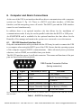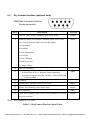
1
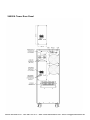
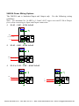
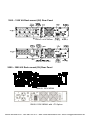
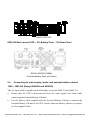
1000 &1000+ SERIES
UPS USERS MANUAL
Phone: 800.894.0412 - Fax: 888.723.4773 - Web: www.ctiautomation.net - Email: [email protected]
IMPORTANT NOTICE
The instructions contained in this manual are not intended to cover all of the details or
variations in equipment, or to provide for every possible contingency concerning
installation, operation, or maintenance. Should further information be required or if
problems arise which are not covered sufficiently, contact your local Toshiba
sales office.
The contents of this instruction manual shall not become a part of or modify any prior or
existing agreement, commitment, or relationship. The sales contract contains the entire
obligation of Toshiba International Corporation (TIC) Uninterruptible Power Systems
(UPS) Division. The warranty contained in the contract between the parties is the sole
warranty of TIC's UPS Division and any statements contained herein do not create new
warranties or modify the existing warranty.
Any electrical or mechanical modifications to this equipment without prior
written consent of Toshiba International Corporation will void all warranties and
may void the UL/CUL listing. Unauthorized modifications can also result in
personal injury, death, or destruction of the equipment.
Phone: 800.894.0412 - Fax: 888.723.4773 - Web: www.ctiautomation.net - Email: [email protected]
UNINTERRUPTIBLE POWER SYSTEM
Complete the information below for the UPS received.
Unless otherwise specified on the warranty card, the warranty period for the UPS or
UPS part is 36 months from the shipment date (see TIC Bill of Lading).
Unless otherwise specified on the warranty card, the warranty period for a UPS battery
is 24 months from the shipment date (see TIC Bill of Lading).
Please complete the following information and retain for your records.
Job Number: ________________________________________________________
Model Number: _____________________________________________________
Serial Number: ______________________________________________________
Application: ________________________________________________________
Shipment Date: ______________________________________________________
Installation Date: ____________________________________________________
Inspected By: _______________________________________________________
January, 2013
Document Number: 57723-010
Phone: 800.894.0412 - Fax: 888.723.4773 - Web: www.ctiautomation.net - Email: [email protected]
Table of Contents
Manual’s Purpose and Scope ................................................................................ V
Contacting Toshiba International Corporation’s Customer Support Center ...... VII
EMC Statements ............................................................................................... VIII
General Safety Instructions .................................................................................. X
Important Safety Instructions ........................................................................... XIII
Instructions Importantes Concernant ...............................................................XVII
Inspection/Storage/Disposal .......................................................................... XVIII
Installation Precautions ..................................................................................... XX
Operating Precautions .....................................................................................XXII
1. Introduction ..................................................................................................... 1
2. System Description ......................................................................................... 1
2.1 General Description ....................................................................................... 2
2.2 Efficiency Optimizer Function ...................................................................... 3
2.3 Auto-Restart .................................................................................................. 4
2.4 Free Run Mode .............................................................................................. 4
2.5 Diagnostic Tests............................................................................................. 4
2.6 System Configuration .................................................................................... 5
3. Storage ............................................................................................................ 6
4. Shipping .......................................................................................................... 6
5. Installation ....................................................................................................... 8
5.1 Environment .................................................................................................. 8
5.2 UPS Frequency Converter Option ................................................................. 8
5.3 Rear Panel Views ........................................................................................... 9
5.4 Connecting to main supply, loads, and external battery cabinet .................. 13
5.5 Front Panel Settings ..................................................................................... 16
6. Computer and Alarm Connections ................................................................ 18
Phone: 800.894.0412 - Fax: 888.723.4773 - Web: www.ctiautomation.net - Email: [email protected]
6.1 RS-232 Standard Interface Port ................................................................... 18
6.2 Dry Contact Interface (optional card) .......................................................... 19
6.3 USB Port ..................................................................................................... 20
6.4 EPO Port (emergency power off) ................................................................ 20
6.5 Network Transient Protector........................................................................ 20
6.6 Load Segments ............................................................................................ 20
7. User’s Guide to Operations ........................................................................... 21
7.1 UPS Startup and Shutdown ......................................................................... 21
7.2 Button Operation ......................................................................................... 21
7.3 Control Panel Functions .............................................................................. 22
7.4 Normal Display ........................................................................................... 23
7.5 UPS Meters Display .................................................................................... 24
7.6 UPS Configurations ..................................................................................... 24
7.7 UPS Manual Test ......................................................................................... 26
7.8 Interpreting UPS Messages ......................................................................... 26
7.9 Audible Alarms............................................................................................ 26
7.10 Silencing an Alarm ...................................................................................... 26
7.11 Troubleshooting ........................................................................................... 27
8. Maintenance .................................................................................................. 28
8.1 Battery Servicing ......................................................................................... 28
9. Technical Specifications ................................................................................ 29
9.1 Power Range 1000-3000 VA (120 V) .......................................................... 29
9.2 Power Range 2400 VA (208/240 V) ............................................................ 30
9.3 Power Range 6000 VA (208/240 V) ............................................................ 31
9.4 Power Range 1000-3000 VA (230 V) .......................................................... 33
9.5 Backup Time at Partial Loads ...................................................................... 34
10. Warranty Information .................................................................................... 35
Appendix A Battery Tray Replacement .............................................................. 38
Phone: 800.894.0412 - Fax: 888.723.4773 - Web: www.ctiautomation.net - Email: [email protected]
Manual’s Purpose and Scope
The purpose of this manual is to provide information on how to safely install, operate,
and maintain your TIC power electronics product. This manual includes a section of
general safety instructions that describes the warning labels and symbols that are used
throughout the manual. Read the manual completely before installing, operating, or
performing maintenance on this equipment.
The scope of this manual is to describe the requirements for an On-Line Uninterruptible
Power System (UPS). The UPS will supply a computer grade AC output sine wave
which is unaffected by the quality of the AC input. The input voltage is single phase and
the output voltage is single phase.
This manual and the accompanying drawings should be considered a permanent part of
the equipment and should be readily available for reference and review. Dimensions
shown in the manual are in metric and/or the English equivalent.
TIC reserves the right, without prior notice, to update information, make product
changes, or to discontinue any product or service identified in this publication.
Phone: 800.894.0412 - Fax: 888.723.4773 - Web: www.ctiautomation.net - Email: [email protected]
TOSHIBA is a registered trademark of Toshiba Corporation. All other product or trade
references appearing in this manual are registered trademarks of their respective
owners.
Toshiba International Corporation (TIC) shall not be liable for direct, indirect,
special, or consequential damages resulting from the use of the information
contained within this manual.
This manual is copyrighted. No part of this manual may be photocopied or reproduced
in any form without the prior written consent of Toshiba International Corporation.
© Copyright 2013 Toshiba International Corporation.
All rights reserved.
Printed in the U.S.A.
Phone: 800.894.0412 - Fax: 888.723.4773 - Web: www.ctiautomation.net - Email: [email protected]
Contacting Toshiba International Corporation’s Customer
Support Center
Toshiba International Corporation’s Customer Support Center can be contacted to
obtain help in resolving any Uninterruptible Power System problems that you may
experience or to provide application information.
The center is open from 8 a.m. to 5 p.m. (CST), Monday through Friday. The Support
Center’s toll free number is US (877) 867-8773, Fax (713) 896-5212.
You may also contact Toshiba International Corporation by writing to:
Toshiba International Corporation
13131 West Little York Road
Houston, Texas 77041-9990
Attn: 1000 Series UPS Product Manager.
For further information on Toshiba International Corporation’s products and
services, please visit our website.
Phone: 800.894.0412 - Fax: 888.723.4773 - Web: www.ctiautomation.net - Email: [email protected]
EMC Statements
FCC Part 15
NOTICE: Pursuant to section 15 of the FCC rules each capacity unit has been tested
and the 1000, 1500, and 2000 VA units comply with the conditions of a Class B digital
device. The product has been established as offering sufficient protection against
dangerous interference for installations in a residential area. The 2400 and 3000 VA
units comply with FCC Section 15 conditions of a Class A digital device. Installation
and use of the equipment should comply with the instructions provided in order to avoid
interference due to the amount of radio frequency energy that is radiated and generated
by the equipment.
TIC cannot assure that no interference will occur. Turn the unit on and off to help
determine if the radio or television reception is found to be influenced by harmful
interference from the equipment. If required, use one of the following measures to
minimize the negative effects of interference:
•
Place the receiving antenna in a separate location or orientation.
•
Increase the distance between the receiver and the equipment.
•
Ensure that your equipment and the receiver are on separate circuits.
•
Contact a technician experienced with radio and TV or a dealer for further
assistance.
ICES-003
This Class A and B Interference Causing Equipment meets all requirements of the
Canadian Interference Causing Equipment Regulations ICES–003. Cet appareil
numérique de la classe A et B respecte toutes les exigences du Reglement sur le matériel
brouilleur du Canada.
Phone: 800.894.0412 - Fax: 888.723.4773 - Web: www.ctiautomation.net - Email: [email protected]
Declaration of Conformity Request
Units labeled with a CE mark comply with the following standards and directives:
Harmonic Standards: EN 62040-1 and EN 62040-2.
EU Directives: 73/23/EEC, Council Directive on equipment designed for use within
certain voltage limits.
2006/95/EC, Amending Directive 93/68/EEC and 73/23/EEC.
89/336/EEC, Council Directive relating to electromagnetic compatibility.
2004/108/EC, Amending Directive 92/31/EEC and 89/336/EEC relating to EMC.
The EC Declaration of Conformity is available upon request for products with a CE
mark.
Phone: 800.894.0412 - Fax: 888.723.4773 - Web: www.ctiautomation.net - Email: [email protected]
General Safety Instructions
DO NOT attempt to install, operate, maintain or dispose of this equipment until you
have read and understood all of the product safety information and directions that are
contained in this instruction manual.
Safety Alert Symbol / Signal Words
The Safety Alert Symbol indicates that a potential personal injury hazard exists. The
symbol is comprised of an equilateral triangle enclosing an exclamation mark.
Signal Words
Listed below are the signal words that are used throughout this manual followed by their
descriptions and associated symbols. When the words DANGER, WARNING, and
CAUTION are used in this manual they will be followed by important safety
information that must be carefully adhered to.
1.
Danger — The word DANGER in capital letters preceded by the safety alert
symbol indicates that an imminently hazardous situation exists that, if not avoided,
will result in death or serious injury to personnel.
DANGER
Phone: 800.894.0412 - Fax: 888.723.4773 - Web: www.ctiautomation.net - Email: [email protected]
2.
Warning — The word WARNING in capital letters preceded by the safety alert
symbol indicates that a potentially hazardous situation exists that, if not avoided,
could result in death or serious injury to personnel.
WARNING
3.
Caution/Attention — The word CAUTION or ATTENTION in capital letters
preceded by the safety alert symbol indicates that a potentially hazardous situation
exists that, if not avoided, may result in minor or moderate injury.
CAUTION / ATTENTION
4.
The word CAUTION without the safety alert symbol indicates a potentially
hazardous situation exists which, if not avoided, may result in equipment and
property damage.
CAUTION
Phone: 800.894.0412 - Fax: 888.723.4773 - Web: www.ctiautomation.net - Email: [email protected]
Special Symbols
Other warning symbols may appear in conjunction with the Danger, Warning, and
Caution symbol and are used to specify special hazards. These warnings describe
particular areas where special care and/or procedures are required in order to prevent
serious injury and possible death.
1.
ELECTRICAL HAZARD SYMBOL – Indicates a hazard that may cause injury
from an electrical shock or burn. The symbol is comprised of an equilateral triangle
enclosing a lightning bolt.
2.
EXPLOSION HARZARD SYMBOL – Indicates a hazard that may cause injury
from exploding parts. It is comprised of an equilateral triangle enclosing an
explosion image.
Phone: 800.894.0412 - Fax: 888.723.4773 - Web: www.ctiautomation.net - Email: [email protected]
Important Safety Instructions
This manual contains important instructions that should be followed during the
installation, maintenance, and operation of the UPS and its batteries to assure safe and
proper operation.
SAVE THESE INSTRUCTIONS
• Disconnect device in the building installation wiring.
• Not for use in a computer room as defined in the Standard for the Protection of
Electronic Computer/Data Processing Equipment, ANSI/NFPA 75.
• CAUTION - To reduce the risk of fire, the input of the unit is connected only to
a circuit provided with 20 amperes maximum branch circuit overcurrent
protection in accordance with the National Electric Code, ANSI/NFPA 70
• CAUTION - Disconnect switch for each ungrounded conductor of ac output
shall be provided by others. To reduce the risk of fire, the output of the unit is
connected in series with branch circuit overcurrent protection for 20 amperes
rating in accordance with the National Electric Code, ANSI/NFPA 70.
• CAUTION - RISK OF EXPLOSION IF BATTERY IS REPLACED BY
AN
INCORRECT
TYPE.
DISPOSE
OF
USED
BATTERIES
ACCORDING TO THE INSTRUCTIONS.
1.
Turn off, lockout, and tagout all power sources before connecting the power wiring
to the equipment or when performing maintenance.
2.
Hardwire type UPS units are not equipped with an over-current protection device,
nor do they have an output disconnect for the ac output. Therefore, a user-installed
circuit breaker should be provided between the UPS output and the load input.
3.
The maximum ambient operating temperature is 40° C (104° F).
4.
Battery servicing should be performed by a qualified Toshiba Representative only.
5.
Unauthorized personnel should not service batteries.
Phone: 800.894.0412 - Fax: 888.723.4773 - Web: www.ctiautomation.net - Email: [email protected]
6.
Contact your nearest Toshiba authorized service center for battery replacement.
Qualified Personnel ONLY!
Qualified Personnel is one that has the skills and knowledge relating to the
construction, installation, operation, and maintenance of the electrical equipment and
has received safety training on the hazards involved (Refer to the latest edition of NFPA
70E for additional safety requirements).
Qualified Personnel shall:
1.
Have read the entire operation manual.
2.
Be trained and authorized to safely energize, de-energize, ground, lockout and tag
circuits and equipment, and clear faults in accordance with established safety
practices.
3.
Be trained in the proper care and use of protective equipment such as safety shoes,
rubber gloves, hard hats, safety glasses, face shields, flash clothing, etc., in
accordance with established safety practices.
4.
Be trained in rendering first aid.
5.
Be knowledgeable of batteries and the required handling and maintenance
precautions.
For further information on workplace safety visit www.osha.gov
WARNING
Misuse of this equipment could result in injury and equipment damage. In no event will
Toshiba Corporation be responsible or liable for either indirect or consequential damage
or injury that may result from the misuse of this equipment.
CAUTION
Do not dispose of the batteries in a fire. The batteries may explode.
Phone: 800.894.0412 - Fax: 888.723.4773 - Web: www.ctiautomation.net - Email: [email protected]
CAUTION
Do not open or mutilate the batteries. Released electrolyte is harmful to the eyes and
skin and could also be toxic.
WARNING
Disconnect charging source prior to connecting or disconnecting battery terminals.
DANGER
A battery can present a risk of electrical shock and high short circuit current.
Phone: 800.894.0412 - Fax: 888.723.4773 - Web: www.ctiautomation.net - Email: [email protected]
—Strict adherence to the following precautions is a requirement when working with
batteries—
Disconnect charging source prior to connecting or disconnecting battery terminals.
To be performed by Qualified Personnel only.
1.
Verify that the UPS is off and that the power cord is disconnected from the power
source.
2.
Disconnect charging source prior to connecting or disconnecting battery terminals.
3.
Remove watches, rings or other metal objects.
4.
Use tools with insulated handles to prevent inadvertent shorts.
5.
Wear rubber gloves and boots.
6.
Do not place tools or any metal parts on top of batteries.
7.
Determine if the battery is inadvertently grounded. If inadvertently grounded,
remove source of ground.
Contact with any part of a grounded battery can result in electrical shock.
The likelihood of shock will be reduced if such grounds are removed prior to
installation or maintenance.
Phone: 800.894.0412 - Fax: 888.723.4773 - Web: www.ctiautomation.net - Email: [email protected]
Instructions Importantes Concernant
LA SÉCURITÉ
CONSERVER CES INSTRUCTIONS
Cette notice contient des instructions importantes concernant la sécurité.
ATTENTION
Une battery peut présenter un risque de choc électrique, de brûlure par transfert d'
énergie.
ATTENTION
L' élimination des batteries est règlementèe. Consulter les codes locaux à cet effet.
Phone: 800.894.0412 - Fax: 888.723.4773 - Web: www.ctiautomation.net - Email: [email protected]
Inspection/Storage/Disposal
CAUTION
Inspection
Upon receipt of the UPS, an inspection for shipping damage should be performed. Use
caution when removing the unit from the pallet. Refer to labels or documentation
attached to packing material.
Uncrating
Check the unit for loose, broken, bent or otherwise damaged parts. If damage has
occurred during shipping, keep all original crating and packing materials for return to
the shipping agent. The warranty does not apply to damage incurred during shipping.
Ensure that the rated capacity and the model number specified on the nameplate
conform to the order specifications.
Storage
During periods of non-use, the following guidelines are recommended for storage.
Storage Preparation
1.
Power up the UPS and allow it to operate with no load for 24 hours to fully charge
the batteries.
2.
Stop the unit.
3.
Disable the COLD START function prior to storing the unit by following the
instructions in section 4. Shipping, page 6.
4.
Ensure the MCCB switch is in the Off position.
Storing Conditions
•
For best results, store the UPS in the original shipping container and place on a
wood or metal pallet.
•
Storage temperature — -4 – 104 °F (-20 – 40 °C).
Phone: 800.894.0412 - Fax: 888.723.4773 - Web: www.ctiautomation.net - Email: [email protected]
•
The optimum storage temperature is 70 °F (21° C). A higher ambient temperature
will require recharging the batteries more frequently during storage.
Avoid the following storage locations:
•
Locations that are subject to extreme temperature changes or high humidity.
•
Locations that are subject to high levels of dust or metal particles.
•
Locations that are subject to excessive vibration.
•
Inclined floor surfaces.
Storage Maintenance
•
If stored at an ambient temperature less than 68 °F (20 °C), recharge the batteries
every 9 months.
•
If stored at an ambient temperature of 68 – 86 °F (20 – 30 °C), recharge the
•
batteries every 6 months.
If stored at an ambient temperature of 86 – 104 °F (30 – 40 °C), recharge the
batteries every 3 months.
Disposal
Please contact your local or state environmental agency for details on disposal of
electrical components and packaging in your particular area.
It is illegal to dump lead-acid batteries in landfills or dispose of improperly.
Please help our Earth by contacting the environmental protection agencies in your area,
the battery manufacturer, or call Toshiba toll-free at (877) 867-8773 for more
information about recycling.
Phone: 800.894.0412 - Fax: 888.723.4773 - Web: www.ctiautomation.net - Email: [email protected]
Installation Precautions
CAUTION
1.
Install the unit in a well-ventilated location; allow at least 4 inches (10 cm) on all
sides for air ventilation and for maintenance.
2.
Install the unit in a stable, level and upright position that is free of excessive
vibration.
3.
Install the unit where the ambient temperature is within the range specified.
4.
Do not install the UPS in areas that are subject to high humidity.
5.
Do not install the UPS in areas that allow exposure to direct sunlight.
6.
Do not install the UPS in areas that allow exposure to high levels of airborne dust,
metal particles, or flammable gases.
7.
Do not install the UPS in areas near sources of electrical noise. Ensuring a proper
earth ground will reduce the effects of electrical noise and will reduce the potential
for electrical shock.
8.
Do not install the UPS in areas that would allow fluids or any foreign object to get
inside the UPS.
9.
The UPS generates and can radiate radio-frequency energy during operation.
Although RFI noise filters are installed inside of the unit, there is no guarantee that
the UPS will not influence some sensitive devices that are operating near by. If such
interference is experienced, the UPS should be installed farther away from the
affected equipment and/or powered from a different source than that of the affected
equipment.
10. The user should provide output over-current protection for hardwired UPS systems.
11. After ensuring that all power sources are turned off and isolated in accordance with
established lockout/tagout procedures, connect the power source wiring of the
correct voltage to the input terminals of the UPS.
Phone: 800.894.0412 - Fax: 888.723.4773 - Web: www.ctiautomation.net - Email: [email protected]
12. Connect the output terminals of the UPS to the load (refer to NEC Article 300 –
Wiring Methods and Article 310 – Conductors For General Wiring). Size the
branch circuit conductors in accordance with NEC Table 310.16.
Conductor Routing and Grounding
1.
Use separate metal conduits for routing the input power, output power, and control
circuits.
2.
Follow the wire size and tightening torque specifications.
3.
Always ground the unit to reduce the potential for electrical shock and to help
reduce electrical noise.
4.
A separate ground cable should be run inside the conduit with the input power,
output power, and control circuits.
CAUTION
THE METAL OF CONDUIT IS NOT AN ACCEPTABLE GROUND.
Phone: 800.894.0412 - Fax: 888.723.4773 - Web: www.ctiautomation.net - Email: [email protected]
Operating Precautions
CAUTION
1.
The UPS should not be powered up until the entire operation manual has been read.
2.
The voltage of the input power source must be within the range of +10% to -30% of
the rated input voltage. The input frequency must be within the rated input
frequency range. Voltages and frequencies outside of the permissible range may
activate the internal protection devices.
3.
The UPS should not be used with a load that has a rated input that is greater than the
rated output of the UPS.
4.
Do not use the UPS to provide power to motors that require high starting current or
with motors that require a long starting time, such as vacuum cleaners and machine
tools (over sizing the UPS for lock rotor current would be required).
5.
Do not insert metal objects or combustible materials in the ventilation slots of the
UPS.
6.
Do not place, hang, or paste any objects on the exterior surfaces of the UPS.
7.
The capacitors of the UPS maintain a residual charge for a while after turning the
UPS off. The required discharge time for each UPS typeform is provided via a
cabinet label and a CHARGE LED. Wait for at least the minimum time indicated on
the label and ensure that the CHARGE LED has gone out before opening the door
of the UPS once the UPS power has been turned off.
8.
Do not attempt to disassemble, modify, or repair the UPS. Call your Toshiba sales
representative for repair information.
9.
Turn the power on only after attaching ALL of the covers.
10. Do Not remove any covers of the UPS when the power is on.
11. If the UPS should emit smoke or an unusual odor or sound, turn the power off
immediately.
Phone: 800.894.0412 - Fax: 888.723.4773 - Web: www.ctiautomation.net - Email: [email protected]
12. The heat sink and other components may become extremely hot to the touch. Allow
the unit to cool before coming in contact with these items.
13. Warning signs should be placed on or near the load as a notification that the load is
being powered by the UPS.
14. Additional warnings and notifications shall be posted at the equipment installation
location as deemed required by Qualified Personnel.
WARNING
While operating in the inverter mode, placing the breaker in the OFF position will
switch the UPS to the battery backup mode. The output of the UPS will continue
uninterrupted to the load. The unit must be in the bypass mode at the time that the
breaker is placed in the OFF position for the UPS to shutdown power to the load.
CAUTION
After an Emergency Power Off (EPO), do not reset the breaker until the UPS has been
fully discharged. The UPS could be damaged if the unit is not fully discharged before
the breaker is reset.
MAINTENANCE NOTE
The 1000 Series UPS is not designed for field-level service. All troubleshooting and
repairs will be done at the Depot-level.
Phone: 800.894.0412 - Fax: 888.723.4773 - Web: www.ctiautomation.net - Email: [email protected]
Phone: 800.894.0412 - Fax: 888.723.4773 - Web: www.ctiautomation.net - Email: [email protected]
1. Introduction
The information provided in this manual covers single phase 1000 – 6000 VA
uninterruptible power systems (UPS). Included in this manual is information on the
installation, operation, safety precautions, shipping, and storage of the equipment.
Installation must be carried out in accordance with this manual. Electrical installations
must also follow local legislation and regulations. Only qualified personnel should
install this equipment. Failure to comply with the warnings and precautions could prove
to be fatal.
2. System Description
The purpose of the UPS is to protect sensitive systems from poor quality utility power,
complete loss of power, or other associated problems. System types include computers,
workstations, process control systems, telecommunications systems, sales terminals, or
other critical instrumentation.
Electrical interference may occur causing problems in AC power. Interference may
come from lightning, the power company, radio transmissions, or motors. Normal
operation of sensitive electrical equipment requires protection against power outages,
low or high voltage levels, frequency variations, differential and common-mode noises,
and transients.
In order to prevent power line problems from reaching critical systems and causing
damage to software, hardware or causing equipment to malfunction, the UPS helps by
maintaining a constant voltage, isolating critical load output, and cleaning the utility AC
power.
Phone: 800.894.0412 - Fax: 888.723.4773 - Web: www.ctiautomation.net - Email: [email protected]
2.1
General Description
As a double conversion on-line UPS, it is able to supply uninterrupted, clean
single-phase power to your critical systems while keeping batteries charged
continuously, even if the utility power fails.
Other features of the UPS includes
•
Auto-Restart feature (See detailed explanation on page 4)
•
Cold Start feature
•
Programmable Load Shed Receptacle
•
Intelligent Charger with Rapid Charge in only 4 hours to 90%
•
Wide Input Voltage Window
•
Wide Input Frequency Window for Complete Generator Compatibility
•
Input Power Factor greater than 0.97
•
Output Power Factor:
1000VA – 0.7
1500VA – 0.7
2000VA – 0.7
2400VA – 0.8
3000VA – 0.7
6000VA – 0.7
•
Multiple Languages LCD Display
•
Efficiency Optimizer Function – See detail explanation on page 3
•
Free Run Mode - See detailed explanation on page 4
•
Diagnostic Tests - See detailed explanation on page 4
•
Optional Network Interface Card, RemotEye II
•
Optional Environmental Monitoring Device
•
Auto-Restart in ON-Line mode after UPS shutdown.
•
No Cold Starts on first use (safety purpose) (See detailed explanation
on page 6)
Phone: 800.894.0412 - Fax: 888.723.4773 - Web: www.ctiautomation.net - Email: [email protected]
See Figure 1 for systems applicable to the UPS system.
Figure 1. Block diagram
•
An input filter reduces transients on the main supply.
•
For maintaining full battery charge, AC power is rectified and regulated in the
rectifier feeding power to the inverter and battery converter.
2.2
•
DC power is converted to AC in the inverter and passes it on to the load.
•
Power to the load is maintained from the battery during a power failure.
•
The converter increases voltage for the inverter as required.
Efficiency Optimizer Function
The Efficiency Optimizer function is a new feature for the UPS that increases the cost
effectiveness of the UPS by minimizing power losses and reduces power consumption.
Alternating between bypass and on-line modes is achieved automatically and in
accordance with the conditions of the utility power. On-line mode may be used during
times of utility power irregularities. The bypass mode should be used when power flows
Phone: 800.894.0412 - Fax: 888.723.4773 - Web: www.ctiautomation.net - Email: [email protected]
smoothly in order to obtain the greatest efficiency. Irregularities can be detected in less
than a second and the on-line mode can be reactivated immediately. Switching back to
online mode occurs when the input voltage exceeds ±10% (or ±15% selectable), when
the input frequency exceeds ±3Hz, or when no input line is available.
Although high efficiency is standard, the default operation is the on-line mode. From
the LCD display panel, Bypass can be activated as required or On-line operation can be
run permanently if preferred.
2.3
Auto-Restart
In the event that a power failure lasts longer than the UPS backup time, the UPS will
shut down. Upon power restoration, the UPS will restart automatically in On-Line mode,
which includes output power being restored to the load and the start of battery recharge.
2.4
Free Run Mode
Free run mode is a mode of operation in which the UPS outputs a pre-set frequency (50
or 60 Hz) regardless of the input frequency. The UPS operates in free run mode when
the input frequency is outside of the selected input frequency range. When starting the
UPS, the targeted frequency is 50 or 60 Hz ±0.25 Hz.
2.5
Diagnostic Tests
When the UPS is started, a diagnostic test is executed automatically that checks the
electronics and battery, and reports any problems on the LCD display.
The advanced battery management system monitors the performance of the battery and
will indicate if battery replacement is required. The battery management system tests
the battery every 30 days of normal mode operation. A battery discharge test is
performed and reports any problems on the LCD display.
Except during the first 24 hours after startup while the UPS is in charging mode,
diagnostic tests can be performed manually from the front panel when required.
Phone: 800.894.0412 - Fax: 888.723.4773 - Web: www.ctiautomation.net - Email: [email protected]
2.6
System Configuration
The UPS device and the internal backup battery make up the system. Depending on the
site and load requirements of the installation, available options may be utilized to create
a tailored solution.
Planning a UPS system should include the following considerations:
•
The total demand of the protected system shall dictate the output power rating (VA).
Allow a margin for future expansion or calculation inaccuracies from measuring
power requirements.
•
Backup time required will determine the battery size needed. If the load is less than
the UPS nominal power rating then the actual backup time will be longer.
Here are the following backup time for each model that is based in a 100% load.
Backup time Internal
Recharge time to 90%
batteries
capacity
UPS 1000VA
7 min
4 hours
UPS 1500VA
6 min
4 hours
UPS 2000VA
6 min
4 hours
UPS 2400VA
11 min
4 hours
UPS 3000VA
5 min
4 hours
UPS 6000VA
7 min
4 hours
Model
The following configuration options are available for enhanced UPS performance:
•
External Battery Cabinets.
(Additional External Battery Cabinets are
available if more back-up time is needed.)
•
Connectivity options (Remote Contact, SNMP/WEB card).
Phone: 800.894.0412 - Fax: 888.723.4773 - Web: www.ctiautomation.net - Email: [email protected]
3. Storage
Please adhere to the following instructions if the UPS is not installed when received:
•
Store the equipment in its original packing and shipping carton.
•
Store the unit in a temperature of 59 – 77 °F (15 – 25 °C).
•
Ensure that the equipment is fully protected from wet or damp areas and from moist
air.
In order to maintain the vitality of the batteries, ensure that the UPS is recharged every 6
months for at least 8 hours during storage.
4. Shipping
The cold start function must be disabled before the UPS is shipped. Cold start applies
power to the UPS output with no UPS input. This can pose a shock or fire hazard if the
output terminals are shorted. Toshiba is not responsible for any resultant fire or damage
if the cold start function is not disabled.
Cold Start Disable Procedure (1000/1500/2000/2400/3000/6000 VA):
1.
Ensure the UPS is switched OFF.
2.
Plug In AC Power.
3.
For 1/1.5/2/3/6kVA UPS: Press and hold the Function Key while pressing the
“Enter” key 3 times.
For 2.4kVA UPS: Press and hold the Function Key while pressing the “Status”
key 3 times.
4.
After a beep sounds, unplug the AC power cord and wait for UPS to shutdown
automatically.
** Note: Cold start will be automatically re-enabled when the UPS is plugged into
commercial power and switched ON.
Phone: 800.894.0412 - Fax: 888.723.4773 - Web: www.ctiautomation.net - Email: [email protected]
The 1000 Series UPS ships with an adhesive patch that covers the ON/OFF Button to
prevent accidentally pressing the On/Off Button during shipping. Follow the above
procedure to disable Cold Start and close the cover to prevent a fire hazard.
Phone: 800.894.0412 - Fax: 888.723.4773 - Web: www.ctiautomation.net - Email: [email protected]
5. Installation
5.1
Environment
To ensure safe and proper operation, ensure that the installation conforms to the
following specifications.
NOTE: Remove the protective plastic adhesive shipping cover over the Off-On
button before turning the UPS On.
Ensure that the installation location is consistent with the following:
•
Avoid extreme temperature and humidity. Maximal battery life can be attained with
a recommended temperature range of 15 °C to 25 °C.
•
Protect the equipment from moisture.
•
Space and ventilation requirements must be met. Ensure there is at least 100mm (4
inch) behind and 50mm (2 inch) on the sides of the UPS for ventilation.
•
Ensure that the front of the UPS remains clear for user access.
The External Battery Cabinets must be installed next to or underneath the UPS.
5.2
UPS Frequency Converter Option
The UPS has an optional software upgrade that allows it to serve as a frequency
converter. Installing this software allows the user to set the UPS output to 50 or 60 Hz
regardless of the input frequency.
This option can be downloaded from the Toshiba website, Follow the home
page menu path to:
UPS>> Options/Accessories>> 1000 series>> Software>>
Frequency Conversion.
** Note: Installing the frequency converter software upgrade will disable the bypass
function. (This insures that in the event of power loss you are not trying to, for example,
run a 50 Hz load with 60 Hz commercial power.)
Phone: 800.894.0412 - Fax: 888.723.4773 - Web: www.ctiautomation.net - Email: [email protected]
5.3
Rear Panel Views
1000VA – 1500VA Tower Rear Panel
USB
USB
EXTERNAL
EXTERNAL
BATTERY
BATTERY
(120V NEMA)
(230V IEC)
2000VA – 3000VA Tower Rear Panel
(120V NEMA)
(230V IEC)
Phone: 800.894.0412 - Fax: 888.723.4773 - Web: www.ctiautomation.net - Email: [email protected]
2400VA Tower Rear Panel
Phone: 800.894.0412 - Fax: 888.723.4773 - Web: www.ctiautomation.net - Email: [email protected]
2400VA Power Wiring Options
The 2400VA unit is hardwired Input and Output only. Use the following wiring
guidelines.
Note – Use minimum No. 14 AWG or 1.5 mm2, 60°C copper wire and 22 Lb-in Torque
force when connecting to Input and Output connection.
1.
X1-X3 – 240V – FULL LOAD
L1
L2
I/L
I/N
G
240
X1
X2
Load MAX 100%
0
N
X3
120
88
0
120
G
120
88
0
120
0
Terminal Block
2.
240
0
O/P
ISO
OPISO
X2-X3 – 208V – FULL LOAD
L1
L2
I/L
I/N
G
X1
208
X2
Load MAX 100%
0
N
X3
120
88
0
120
G
120
88
0
120
0
Terminal Block
3.
240
0
O/P
ISO
OPISO
X1-N or N-X3 – 120V – HALF LOAD
L1
L2
I/L
I/N
L1
L2
120
X1
Load MAX 50%
0
X2
N
X3
I/L
I/N
G
G
120
88
0
120
G
Terminal Block
120
88
0
120
0
240
0
O/P
ISO
OPISO
X1
X2
0
120
Load MAX 50%
N
X3
120
88
0
120
G
Terminal Block
120
88
0
120
0
240
0
O/P
ISO
OPISO
Phone: 800.894.0412 - Fax: 888.723.4773 - Web: www.ctiautomation.net - Email: [email protected]
1000 – 1500 VA Rack mount (2U) Rear Panel
RM-2U 120V NEMA
RM-2U 230V IEC
2000 – 3000 VA Rack mount (2U) Rear Panel
RM-2U 120V NEMA
RM-2U 120V NEMA with –P1 Option
Phone: 800.894.0412 - Fax: 888.723.4773 - Web: www.ctiautomation.net - Email: [email protected]
RM-2U 230V IEC
6000 VA Rack mount (UPS – 3U, Battery Pack – 3U) Rear Panel
RM-6U 208/240V NEMA
(Includes Battery Pack, not shown)
5.4
Connecting to main supply, loads, and external battery cabinet
1000 – 3000 VA (Except 2400VA and 6000VA)
The AC input cable is supplied with all models except the 2400 VA and 6000 VA.
•
Ensure that the UPS is disconnected from the main supply and loads while
connecting the External Battery Cabinets.
•
Use the battery cable supplied with the External Battery Cabinet to connect the
External Battery Cabinet to the UPS. If more than one battery cabinet is required,
use the supplied cable.
Phone: 800.894.0412 - Fax: 888.723.4773 - Web: www.ctiautomation.net - Email: [email protected]
•
A familiarity with the UPS parameter settings is required if changing the Battery
pack quantity as when using the External Battery Cabinets.
•
Connect the input cable to the UPS and connect the other end to a grounded outlet.
The batteries will charge automatically when connected to the main supply.
The UPS may be used immediately to power a load. However, the maximum
battery back-up time will not be available until the recommended 8-hour minimum
charge time has completed.
•
If a Site Wiring Fault is displayed, rotate the connector.
•
After charging the UPS, connect the load to the UPS.
•
Do not connect any devices to the UPS that may cause overloading of the UPS or
that draws half-wave rectified current, such as hair dryers or vacuum cleaners.
•
See section 6 Computer and Alarm Connections if computer or alarm (rear panel)
connections are used.
•
The installation is now complete.
Figure 2 Example of Installation of Plug & Play products.
2400 VA
The 2400 VA UPS input and output power is hardwired to the power terminals. The
output of the UPS can be adjusted according to which output terminals are selected. See
2400VA Power Wiring Options, page 11.
Phone: 800.894.0412 - Fax: 888.723.4773 - Web: www.ctiautomation.net - Email: [email protected]
6000 VA
The 6000 VA UPS comes in two sections, a Power Module and the Battery Pack. Each
unit is RM-3U tall. The input power is hardwired to the UPS power input terminals.
The UPS accepts either 208V or 240V input. The UPS autosenses the input voltage and
provides the corresponding output voltage (208V or 240V). The UPS provides two
L6-30R receptacles.
•
Ensure that the UPS Main Circuit Breaker is open, and the UPS loads are
disconnected while connecting the External Battery Cabinet/s.
•
Use the battery cable supplied with the External Battery Cabinet to connect the
External Battery Cabinet to the UPS. If more than one battery cabinet is required,
use the supplied cable. The batteries will charge automatically when connected to
the main supply.
NOTE: The UPS may be used immediately to power a load. However, the
maximum battery back-up time will not be available until the recommended 8-hour
minimum charge time has completed.
•
After charging the UPS, connect the load to the UPS.
Phone: 800.894.0412 - Fax: 888.723.4773 - Web: www.ctiautomation.net - Email: [email protected]
5.5
Front Panel Settings
Listed below are the default settings of the primary UPS parameters.
Settings
Options
Default
Remarks
1) O/P VOLT SET
(output voltage
set)
100/110/115/120/127
208/220/230/240 Vac
120 V
230 V
120 V (FOR LV series)
230 V (FOR HV series)
2) I/P FREQ SET
(input frequency
setting)
3) I/P BYPASS
SET
(input bypass
setting)
4) FREE RUN
SET
+/- 2%
+/- 5%
+/- 7%
+/- 10%
+10% -15%
+15% -20%
+/- 5%
Input Frequency range in
Free Run mode
+10%
-15%
Input Voltage range when
Bypass mode is on
ON/OFF
ON
If ON, enable UPS runs on
Asynchronous mode.
For example:
If input freq 55Hz
output freq stays at 60Hz.
5) HE MODE SET
6) MANUAL
BYPASS
ON/OFF
ON/OFF
OFF
OFF
If OFF, disable UPS runs on
synchronous mode.
For example:
If input freq 55Hz,
UPS will go to battery mode.
If ON, enable UPS runs in
High efficiency mode. The
unit will be in bypass mode
with 95% or higher
efficiency.
If OFF, the unit will be in the
online mode with 85%
efficiency.
If ON, enable UPS switch to
Bypass mode immediately.
Phone: 800.894.0412 - Fax: 888.723.4773 - Web: www.ctiautomation.net - Email: [email protected]
Settings
7) OUTLET
SETTING
Options
Default
Option 1
8)BATTERY TEST
GROUP1/GROUP2
Option 1: 1 On /2 On
Option 2: 1 Off /2 On
Option 3: 1 Off /2 Off
Option 4: 1 On /2 Off
TEST?
9) SILENCE SET
ON/OFF
OFF
10)BAT CABINET
SET
0: EXT B. PACKS
1: EXT B. PACKS
2: EXT B. PACKS
0
11) SITE FAULT
SET
ENABLE/DISABLE
DISABLE
12) LANGUAGE
ENGLISH
GERMAN
FRENCH
SPANISH
ITALIAN
ENGLISH
13) GENERATOR
ON/OFF
OFF
14) RS232
CONTROL
ENABLE/DISABLE
ENABLE
Remarks
This is a load-shed feature.
Perform battery test
immediately
Shown options when battery
Cabinets are connected
Alarm on main computer
connected at wrong polarity
or
Installation to main supply
without group.
If ON, UPS will work with a
wide range of voltages and
frequencies, without
switching back and forth
between Line and Battery
mode.
Option to enable and disable
the RS232 port. USB share
the communication line with
RS232. Only one option may
be used at a time.
Complete the installation entirely before changing the default settings or connecting a load to the
UPS.
Phone: 800.894.0412 - Fax: 888.723.4773 - Web: www.ctiautomation.net - Email: [email protected]
6. Computer and Alarm Connections
At the rear of the UPS is an interface that allows direct communication with a computer
system (see Figure 2, Pg. 14). There is a RS232 serial data interface, a USB data
interface, and an emergency power off switch. The RS232 port and the USB interface
cannot be used simultaneously.
In addition there is an optional interface slot that allows for the installation of
communications cards. It may be used in parallel with either the RS232 or USB ports.
An SNMP/WEB card is available for the optional interface slot that allows for the
RemotEye II to manage and monitor the system over a network or over the internet.
6.1
RS-232 Standard Interface Port
Only the communication cable provided with the UPS may be used to connect the UPS
to a computer when using the RS232 port of the UPS. Ensure that the operating system
of the computer supports RS232 communications. Other advanced power protection
solutions, such as SNMP, are available from your dealer.
The RS-232 interface uses a 9-pin D-sub connector. The names and functions of the port
pins are listed in the following table.
DB9 Female Connector Outline
(facing connector)
Pin #
Signal
Direction (re UPS)
Functions
2
TxD
Output
TxD Output
3
RxD
Input
RxD / Inverter Off Input
5
Common
Common
6
Output (Normally Open) AC Fail (13VDC)
8
Output (Normally Open) Low Battery (13VDC)
9
Output
8–24 VDC Power
Note: In Battery mode, the UPS will be turned off 2 minutes after 5V is applied to Pin 3 and Pin 5 for more
than 5seconds.
Table 1 : RS232 Pin Out Signal
Phone: 800.894.0412 - Fax: 888.723.4773 - Web: www.ctiautomation.net - Email: [email protected]
6.2
Dry Contact Interface (optional card)
DB9 Male Connector Outline
(facing connector)
Pin #
Description
I/O Type
1
UPS fail, relay contact, normally open, active close.
output
2
Summary alarm, relay contact, normally open, active close.
output
One of the following signals activate this signal:
1) Output fault
2) Bus fault
3) Over temperature
4) Overload
5) Over Charging
6) Battery test fail
7) Charger failure
3
4
GND for secondary
Remote shutdown
• Short Pin 4 & Pin 5: Remote Output Shutdown
• Remove short between Pin 4 & Pin 5: UPS switch back
to Inverter/Run
input
5
Common
6
Bypass active, normally open, active close
output
7
Battery low, normally open, active close
output
8
No connection
input
9
Utility fail, normally open, active close (Requires 2 seconds
output
for pin to activate)
Note: Vcc Voltage is 9-12 Vdc.
Table 2 : DryContact Pin Out Signal Chart
Phone: 800.894.0412 - Fax: 888.723.4773 - Web: www.ctiautomation.net - Email: [email protected]
6.3
USB Port
Connecting the UPS to a computer using the USB port of the computer requires USB
compliant hardware, PC operating system support, and a UPS driver. The RS232 serial
port cannot be used when using the USB port. The USB cable is a standard cable and
may be purchased separately.
6.4
EPO Port (emergency power off)
A customer-supplied switch located remotely may be used to open the EPO connection
and force the UPS output receptacles to be switched off. The EPO function shuts down
the equipment immediately. An EPO will not provide an orderly shutdown. The UPS
will have to be manually restarted in order to regain power to the outlets.
After an Emergency Power Off (EPO), do not reset the breaker until the UPS has been
fully discharged. The UPS could be damaged if the unit is not fully discharged before
the breaker is reset.
6.5
Network Transient Protector
The network transient protector, located on the back panel, has both IN and OUT RJ45
10 baseT jacks and will protect a single network connector. Connect the input connector
to the jack labeled IN, and the output connector to the jack labeled OUT.
6.6
Load Segments
The sets of receptacles known as load segments provide organized shutdown and
startup of the equipment. Less critical equipment can be turned off during power
outages saving battery power for critical loads. The load group status can be viewed
from the LCD display and can be changed if necessary.
Phone: 800.894.0412 - Fax: 888.723.4773 - Web: www.ctiautomation.net - Email: [email protected]
7. User’s Guide to Operations
Normal ongoing UPS operation requires little or no user input. Startup and
shutdown requirements of the user are discussed in this section.
7.1
UPS Startup and Shutdown
Starting the UPS
•
Ensure that installation is correct and that the input power cable is connected to a
properly grounded outlet.
•
Start the UPS by pressing the On/Off button on the front panel.
•
The UPS will start the inspection of internal functions, main synchronization, and
inverter startup. A successful completion allows for output power via the outlets.
•
During the startup inspection the LCD will display Ready On. The LED will light
up when output power has started and the LCD display will show Line Mode.
•
Apply power to the load.
Shutting Down the UPS
•
Shut off and disconnect the load.
•
Press and hold the UPS On/Off button for five seconds. The alarm will sound and
the UPS will shut down.
•
The LCD will momentarily display UPS OFF.
Note: In emergency situations the EPO should be used.
7.2
Button Operation
1. “
” or ON/OFF is the UPS ON/OFF button.
(a) Press and hold the ON/OFF button for at least 3 seconds to turn on the UPS.
(b) When the UPS is operating, press and hold the Load ON/OFF button for at least
3 seconds to turn off the UPS.
Phone: 800.894.0412 - Fax: 888.723.4773 - Web: www.ctiautomation.net - Email: [email protected]
2. “
” or ENTER is the Enter button.
(a) Press and hold the Enter button for at least 2 seconds to read the parameter
settings of the UPS. Press the Enter button again to cycle through each successive
parameter.
(b) Ten seconds of inactivity will return the display to the original status.
3. “
” or FUNC is the Function button.
(a) Press and hold the Function button for at least 2 seconds to access the selectable
parameters. Press the Function button again to cycle through each successive
selectable parameter.
(b) Press the Enter button to view or change the displayed parameter.
(c) Ten seconds of inactivity will return the display to the original status.
4.
STATUS (2400/6000VA Only) will display the UPS data.
(a) Press and hold the Status button for at least 2 seconds to read the parameter
settings of the UPS. Press the Enter button again to cycle through each successive
parameter.
(b) Ten seconds of inactivity will return the display to the original status.
5.
ESCAPE (2400/6000VA Only) – Press Escape to return to the main display
immediately.
7.3
Control Panel Functions
The front panel is composed of five LED indicators, an LCD screen, and a speaker for
audible alarms.
Rack-mounted units have international symbols stenciled next to the LED indicators
instead of text.
ON/OFF or
— is on when the UPS is turned on (green).
ON-LINE or
— is on when in the Normal or Static Bypass modes. Also
indicates that there is voltage at the output terminals (green).
ON-BAT or
— is on while operating in the Battery mode.
BYPASS or
— is on while operating in the Bypass mode (yellow).
Phone: 800.894.0412 - Fax: 888.723.4773 - Web: www.ctiautomation.net - Email: [email protected]
FAULT or
— is on during active UPS internal errors (red). FAULT is
accompanied by an audible alarm. Press any of the front panel
buttons to cancel the alarm.
Status of the UPS, measurements, and alarms are all indicated on the LCD screen.
Rack Unit
Tower Unit
ON
ON-LINE ON-BATT BYPASS FAULT
FUNC
ENTER
ON/OFF
Figure 3 Control panels – 1000/1500/2000/3000VA
Figure 4 Control panel – 2400VA Tower/6000VA Rack Unit
7.4
Normal Display
The UPS status is shown in the normal display mode. The UPS Meters display and the
Setting display may be accessed by pressing the Return button on Tower Unit and
FUNC button on the Rack Unit.
Phone: 800.894.0412 - Fax: 888.723.4773 - Web: www.ctiautomation.net - Email: [email protected]
7.5
UPS Meters Display
Listed below are the parameters available for viewing from the UPS meters display.
Press this button to scroll through the parameters.
LCD Message
Description
O/P VOLT= xxx.xV
Shows Output AC Voltage
O/P FREQ= xx.x Hz
Shows Output Frequency
I/P VOL T= xxx.xV
Shows Input AC Voltage
I/P FREQ= xx.x Hz
Shows Input Frequency
BAT VOLT= xx.xV
Shows Battery Voltage
O/P LOAD%= xx%
Shows Load % of Max Load
O/P W= xW
Shows Output Watts
O/P VA= xVA
Shows Output VA
O/P CURR= xA
Shows Output Current
BACKUP TIME= xx min Shows Estimated Backup Time in Minutes
BAT CHARG= xx%
Shows Approximate Percentage of Battery Capacity
TEMPERATURE= xxC
Shows Approximate Ambient Temperature
BAT PACK NUM= x
Shows External Battery Pack Number
RATING = xxxxVA
Shows UPS Rating
CPU VERSION xx.x
Shows CPU Version
7.6
UPS Configurations
1) Parameter settings may be viewed from the UPS Settings display.
2) To enter the configuration mode, press and hold the Function button for one second.
The first configuration parameter will be shown on the LCD display.
3) Press the Function button again to scroll through the remaining parameters.
Phone: 800.894.0412 - Fax: 888.723.4773 - Web: www.ctiautomation.net - Email: [email protected]
4) Press the Enter button to select a displayed parameter.
5) Press the Function button to scroll through the options for the selected parameter.
Press the Enter button to select the setting.
6) If prompted to save the selection, press the Enter button to either confirm or save
the selection. See the table on page 16 for a complete listing of the user-settable
parameters.
7) If there is no user input for ten seconds, the UPS will exit the configuration mode
and return to normal mode displaying Line mode.
Phone: 800.894.0412 - Fax: 888.723.4773 - Web: www.ctiautomation.net - Email: [email protected]
7.7
UPS Manual Test
Manual UPS and Battery tests may be performed from the UPS configuration screen.
Tests may be performed when the battery is not being charged.
To run the battery test scroll to the “Manual Bat Test” parameter press the Enter button
twice.
** Note: In order for the UPS to operate normally, Manual Bypass should always be set
to OFF because the load will not be protected by the unit when Manual Bypass is ON.
*** Note: Turn off the UPS and keep the AC power on to use the Generator function.
(go to normal mode for \Generator\OFF).
7.8
Interpreting UPS Messages
Troubleshooting procedures described here provide instructions to be used to isolate
UPS malfunctions.
Start the troubleshooting procedure in the event of a control panel alarm.
7.9
•
Audible Alarms
While operating on battery power (ON BAT LED is on) the UPS will beep once at
5-second intervals.
•
While operating on battery power and the battery power is low (ON BAT LED is
flashing) the UPS will beep twice at 5-second intervals.
•
In the event of an internal fault with an active alarm (ALARM LED is on), the UPS
will provide a constant audible alarm and display an error message on the LCD
display.
•
While operating in the Bypass mode (BYPASS LED is on) the UPS will not beep.
7.10 Silencing an Alarm
With the exception of a LOW BATTERY Alarm, pressing any of the front panel buttons
will turn off the alarm. Select Silent Alarm Mode to disable all audible alarms.
Phone: 800.894.0412 - Fax: 888.723.4773 - Web: www.ctiautomation.net - Email: [email protected]
7.11 Troubleshooting
Displayed on LCD
Output Overload
Audible Alarm
Alarm Description
Two Beeps/sec The UPS is overloaded (in
Line Mode). More power
required than the UPS can
provide. The UPS operates
in bypass.
What You Should Do
Remove loads from the UPS; least to
most critical. If this solves the
problem, the UPS will return to
normal operation.
Battery Test
No Beeps
No action needed.
Battery test active.
User Notification only.
Over-Charge
Low Battery
On-Battery
Charger Failure
Over-Temperature
Constant Beep Overcharged Batteries.
Turn off loads. Turn off UPS.
Call service @ 1-877-867-8773
2 Beeps/5 sec UPS operating on Battery The unit will restart
Power and will shut down Automatically when acceptable
soon due to low battery power returns.
voltage.
1 Beep/5 sec UPS operating on Battery Save your data and perform a
Power.
controlled shutdown.
Constant Beep Failed Charger.
Call service @ 1-877-867-8773
Constant Beep High ambient
Temperature.
Output Short
Constant Beep Output short circuit.
High output Voltage Constant Beep High output voltage.
Low Output Voltage Constant Beep Low output voltage.
Bus Fault
2 Beeps/sec
Site Wiring Fault
1 Beep/sec
Line Abnormal
1 Beep/sec
High internal DC bus
Voltage.
Voltage detected between
neutral and ground.
Ensure that the UPS fans and
vents are not blocked, and that
the ambient temp. is < 40° C. If
problem persists call service @
1-877-867-8773
Call service @ 1-877-867-8773
Call service @ 1-877-867-8773
Call service @ 1-877-867-8773
Turn off loads. Turn off UPS.
Call service @ 1-877-867-8773
UPS main connector has wrong
polarity. Rotate the connector
(Schuko-electric contact). UPS
installed to main supply without
ground. See section 5.5 for
information on how to disable
the Site wiring alarm.
Wrong AC Line backed
up during auto restart.
Phone: 800.894.0412 - Fax: 888.723.4773 - Web: www.ctiautomation.net - Email: [email protected]
8. Maintenance
With a minimal amount of maintenance you can expect years of satisfactory operation
from the UPS unit. The most critical issues for the reliability of the UPS are
environmental issues. Ensure that the temperature and humidity are always in
accordance with the specifications and keep the area around the unit clean and dust free.
The typical battery lifetime is 4 years when operated at 77° (25 °C).
Check the back-up time capability of the UPS/battery at 6 to 12 month intervals to
ensure adequate support for the application.
8.1
Battery Servicing
Servicing of batteries should be performed or supervised by personnel knowledgeable
about batteries and the required precautions. See IMPORTANT SAFETY
INSTRUCTIONS – Qualified Personnel.
CAUTION – When replacing batteries, replace with the same type and number of
batteries.
Battery Type: Lead-Acid Type
Battery Rating: Total DC 72V, 96 Ah. (6 Pcs Battery/SET, 2 SET)
Replacement batteries available:
Manufacturer
TAIWAN YUASA BATTERY CO LTD
Type
Rating
REW45-12
12 Vdc, 8.0 Ah
REW45-12FR
12 Vdc, 8.0 Ah
(MH28947)
Phone: 800.894.0412 - Fax: 888.723.4773 - Web: www.ctiautomation.net - Email: [email protected]
9. Technical Specifications
9.1
Power Range 1000-3000 VA (120 V)
Tower
Rackmount (2U)
Input
US 120V Model UT1A1A010C6
UT1A1A015C6
UT1A1A020C6
UT1A1A030C6
US 120V Model UT1A1A010C6R UT1A1A015C6R UT1A1A020C6R UT1A1A030C6R
KB2
KB2
KB2
KB2
Voltage
120 VAC (80 – 144 V)
Voltage Range
+20% to -33%
Frequency
50 / 60 Hz auto sensing
Power Factor
Greater than 0.97
Topology
True on-line Double conversion Input PF correction
Voltage
120 VAC
Output
Capacity (VA)
1000 VA
1500 VA
2000 VA
3000 VA
Capacity (W)
700 W
1050 W
1400 W
2100 W
Frequency
50 / 60 Hz auto sensing *
Wave Form
Sine wave, zero transfer time
Load Power
0.70
Factor
Efficiency
Greater than 86%
Greater than
AC/DC/AC
85%
Rated Current
8.3 A
12.5 A
16.6 A
25 A
Overload
125% for 1 min 150% for 10 sec
125% for 1 min
Capacity
130% for 10
sec
Crest Factor
3.0 at full load
2.5 at full load
DC Voltage
36 V / 12 V
72V / 12 V
Battery
(Tower & 2U)
9 AH x 3
9 AH x 6
Backup Time
7 min
6 min
6 min
5 min
(Tower & 2U)
(full load)
(full load)
(full load)
(full load)
Interface
RS-232 and USB standard RemotEye II® and EMD option
Dimensions
16.5”L x 6.0”W x 9.4”H
16.7"L x 8.9"W x 14.2"H
Physical
(Tower)
Dimensions
16.7”L x 16.9”W x 3.5”H
25.0"L x 16.9"W x 3.5"H
(2U)
Weight
35.6 lbs /
37.4 lbs /
68.4 lbs /
72.6 lbs /
(Tower/2U)
37.6 lbs
37.6 lbs
69.5 lbs
71.5 lbs
Line Cord
5-15P
5-20P
L5-30P
Receptacles
NEMA 5 - 15 P (6 / 6)
Tower - NEMA 5-20 P (12)
(Tower/2U)
2U - NEMA 5-15 P (4)
Environ-ment Operating
32 – 104°F (0 – 40°C)
Temperature
Altitude
11500 ft (3500 m) above sea level
Three years on electronics
Warranty
Two years full replacement on battery (See Toshiba warranty policy for full
details.)
•
Output frequency can hard set at 50 or 60 Hz by installing an optional software upgrade. This upgrade enables the user
to select a fixed output frequency and simultaneously disables the bypass mode.
Standards - Safety:UL-1778, Emissions: FCC Part 15 Class B (1000-2000 VA) FCC Part 15 Class A (3000 VA)
Phone: 800.894.0412 - Fax: 888.723.4773 - Web: www.ctiautomation.net - Email: [email protected]
9.2
Power Range 2400 VA (208/240 V)
Tower
Input
Output
Battery
Physical
Environmen
t
US 208/240 Model
Voltage
Voltage Range
Frequency
Power Factor
Topology
Voltage
Capacity (VA)
Capacity (W)
Frequency
Wave Form
Load Power Factor
Efficiency
AC/DC/AC
Rated Current
Overload Capacity
Crest Factor
DC Voltage
Backup Time
Interface
Dimensions
Weight
Line Cord
Receptacles
Operating
Temperature
Altitude
UT1G2L024C6T
208 or 240 VAC (161 – 276 V)
+15% to -34%
50 / 60 Hz auto sensing
Greater than 0.97
True on-line Double conversion Input PF correction
120/208/240 VAC
2400 VA
1920 W
50 / 60 (45-65) Hz auto sensing *
Sine wave, zero transfer time
0.8
Greater than 87%
10 A @ 240V
125% for 1 min 130% for 10 sec
3.0 at full load
72V / 12 V (9 AH x 6)
11 min (full load)
RS-232 and USB standard RemotEye II® and EMD option
23.2”L x 10.1”W x 27.6”H
154.3 lbs
None (Hardwired)
None (Hardwired)
32 – 104°F (0 – 40°C)
3300 ft (1000 m) above sea level
Three years on electronics
Two years full replacement on battery (See Toshiba warranty policy for
full details.)
•
Output frequency can hard set at 50 or 60 Hz by installing an optional software upgrade. This upgrade enables the user
to select a fixed output frequency and simultaneously disables the bypass mode.
Standards – FCC Part 15 Class A (2-3kVA), UL 1778, ICES-0003
Safety – EN 62040-1, Emissions: EN 62040-2, Immunity: EN 62040-2 Category C2
Warranty
Phone: 800.894.0412 - Fax: 888.723.4773 - Web: www.ctiautomation.net - Email: [email protected]
9.3
Power Range 6000 VA (208/240 V)
1000 Series 6kVA Specification
Specification
Rackmount
General
Input
Bypass
Output
US 208/240V
Topology
Certifications
Voltage (V)
Capacity (VA)
Frequency
Frequency Synchronization
Power Factor
Current THD
Cold Start (0 to 100% load)
Earth leakage (max.)
Voltage (V)
Voltage
Voltage Regulations
Capacity (W)
Frequency
Battery Mode/Free Run Mode
Wave Form
Load Power Factor
Efficiency AC/DC/AC
High Efficiency Mode Efficiency
Rated Current (based on 240V)
Inverter Overload Capacity
Crest Factor
Voltage Transient Response
(battery mode with R type load)
Voltage Transient Recovery (R
type Load)
On-line Transfer Time – Inverter to
Bypass and Bypass to Inverter
High Efficiency Transfer Time –
Inverter to Bypass and Bypass to
Inverter
Short Circuit Protection
Voltage Total Harmonic Distortion
(Full Linear Load)
Voltage Total Harmonic Distortion
(Full Non-Linear Load)
Steady State Output Voltage
Regulation
Common Mode Noise
Leakage Current
Surge Protection
UT1G1G060C6RKB3 + UT1-BR-0607
True on-line, Double conversion, IGBT Power Factor Correction
Input
CE
Single Phase - 208/240Vin
6kVA
45-65 Hz auto sensing
± 3Hz
Greater than 0.97
Less than 15%
Default Output Frequency 60 Hz
2mA (UPS only)
+10/-15% of nominal (default)
+10/-10% of nominal
+15/-20% of nominal
Set by display panel
208V or 240V
± 3%
4.2kW
50 / 60 Hz auto sensing
± 0.25 Hz
Sine wave, zero transfer time
0.7 PF
Greater than 89% at Nominal Voltage
Greater than 92%
25.0
125% for 1 min, 150% for 10 sec
3.0 at full load
0%100%0%; ± 15 % max.
20%100%20%; ± 9 % max.
Return to nominal voltage within 30 ms
Less than 4m sec
Less than 4m sec transfer time
Electronic overload and short circuit.
Less than 3 % THD
Less than 5 % THD
No-load to Full-load +/- 2% at full battery.
less than 0.5Vrms
.5mA
MOV 260 Jules on Output
Phone: 800.894.0412 - Fax: 888.723.4773 - Web: www.ctiautomation.net - Email: [email protected]
Battery
Acceptable manufacturer
Type / Rating
Back-up Time at Full Load (at 25
degree C) (min)
Battery Bus Voltage (VDC)
Number of Batteries
Recharge
Battery Mode Voltage Regulation
Battery Leakage
Battery Test
Replaceable Batteries
Battery Protection
Pre-alarm Level
Battery Level @ Shutdown
Overcharge Protection
Temperature Compensated Charger
Voltage Level
Environment
Mechanical
Protection against Batteries Deep
Discharge
Operating Temperature
Storage Temperature
Operating Humidity
Altitude
Acoustical Noise
Heat Generation (BTU/Hour)
Dimensions (Rackmount) LxWxH
Weight (Rackmount)
Line Cord
Receptacles
Enclosure
Paint System
Front Panel
Connectors/Options
Buzzer Volume
Warranty
Yuasa Taiwan only
9AH/12V Valve Regulated Lead Acid, Flame Retardant
7 minutes
240
20
4 hours to 90% for all ratings
±3% RMS for entire battery voltage range and 0 to 100% load
100 mA maximum
Automatic and Manual
Not Hot-Swappable
Fuse
2 minutes
1.67 VPC, ± 3% of battery voltage at FL with level automatically
raised for lighter loading
2.50 VPC, ± 3% of battery voltage
Maintains proper float voltage per battery specification over a
temperature range of 10 to 40 degree C (2.3V/cell at 25 degree C
with a temperature coefficient of minus 5 millivolts per degree
C)
2.25 minimum, 2.275 nominal, 2.30V maximum voltage of
battery voltage
0 - 40oC (32 - 104oF)
-20 - 40oC (-4 - 104oF)
30-90% (No Condensation)
11500 ft (3500 m) above sea level
50dB(A) maximum at 1 meter from Front Panel
2234BTU/Hour
16.8 in. x23.5 in. x10.5 in. (427 mm x 597mm x 267mm)
148lbs (67.1 kg)
Terminal Block with L6-30P (option to remove the L6-30P)
(2) L6-30R
Enclosure of unit made from sheet metal meets NEMA 1 and UL
Type 1 Standard
Black Color
1000 Series Panel
EPO
Battery Connectors
Option card Slot (Network and Dry Contact)
Mute/Unmute
Three years on electronics
Two years full replacement on battery (See Toshiba warranty
policy for full details.)
•
Output frequency can hard set at 50 or 60 Hz by installing an optional software upgrade. This upgrade enables the user
to select a fixed output frequency and simultaneously disables the bypass mode.
Standards – FCC Part 15 Class A (2-3kVA), UL 1778, ICES-0003
Safety – EN 62040-1, Emissions: EN 62040-2, Immunity: EN 62040-2 Category C2
Phone: 800.894.0412 - Fax: 888.723.4773 - Web: www.ctiautomation.net - Email: [email protected]
9.4
Power Range 1000-3000 VA (230 V)
Tower
Rackmount (2U)
Input
Output
Battery
Physical
Environment
Warranty
International
230V Model
International
230V Model
Voltage
(International)
Voltage Range
(International)
Frequency
Power Factor
Topology
Voltage
(International)
Capacity (VA)
Capacity (W)
Frequency
Wave Form
Load Power
Factor
Efficiency
AC/DC/AC
Rated Current
(International)
Overload
Capacity
Crest Factor
DC Voltage
(Tower & 2U)
Backup Time
(Tower & 2U)
Interface
Dimensions
(Tower)
Dimensions
(2U)
Weight
(Tower/2U)
Line Cord
(International)
Receptacles
(Tower/2U)
International
Operating
Temperature
Altitude
UT1E1E010C6
UT1E1E015C6
UT1E1E020C6
UT1E1E010C6
RKB2
UT1E1E015C6
UT1E1E020C6
RKB2
RKB2
230 VAC (161 – 276 V)
UT1E1E030C6
UT1E1E030C6RKB
2
+20% to -30%
50 / 60 Hz auto sensing
Greater than 0.97
True on-line, Double conversion Input PF correction
230 VAC
1000 VA
700 W
1500 VA
2000 VA
1050 W
1400 W
50 / 60 Hz auto sensing*
Sine wave, zero transfer time
0.7
Greater than 86%
4.3 A
6.5 A
3000 VA
2100 W
Greater than 85%
13 A
13 A
125% for 1 min., 150% for 10 sec.
125% for 1 min.,
130% for 10 sec.
3.0 at full load
2.5 at full load
36 V / 12 V
72V / 12 V
9 AH x 3
9 AH x 6
7 min
6 min
5 min
5 min
(full load)
(full load)
(full load)
(full load)
RS-232 and USB standard RemotEye II® and EMD option
16.5”L x 6.0”W x 9.4”H
16.7" L x 8.9" W
16.7" L x 8.9" W x
x 14.2" H
14.2" H
16.7”L x 16.9”W x 3.5”H
25.0"L x 16.9"W
25.0"L x 16.9"W x
x 3.5"H"
3.5"H"
35.6 lbs /
37.4 lbs /
68.4 lbs /
72.6 lbs / 71.5 lbs
37.6 lbs
37.6 lbs
69.5 lbs
IEC 320
IEC 320 (4 / 4)
IEC 320 (8 / 4)
IEC 320 (8 / 4)
32 – 104°F (0 – 40°C)
11,500 ft (3500 m) above sea level
Three years on electronics
Two years full replacement on battery (See Toshiba warranty policy for full details.)
Output frequency can hard set at 50 or 60 Hz by installing an optional software upgrade. This upgrade enables the user to
select a fixed output frequency and simultaneously disables the bypass mode.
Standards - Safety: EN 62040-1, Emissions: EN 62040-2, Immunity: EN 62040-2 Category C1 (1000-2000VA), EN 62040-2
Category C2 (2000-3000VA
Phone: 800.894.0412 - Fax: 888.723.4773 - Web: www.ctiautomation.net - Email: [email protected]
9.5
Backup Time at Partial Loads
Below is the estimated backup time at various fractions of full load for each 1000 Series
model. This table assumes the batteries are fresh and begin with a .full initial charge
Load
10% 20% 30% 40% 50% 60% 70% 80% 90% 100%
1000 VA Backup (min)
150
56
38
30
23
19
15
12
10
7
1500 VA Backup (min)
80
37
21
19
18
15
13
11
8
6
2000 VA Backup (min)
150
68
38
26
19
14
11
9
7
6
2400 VA Backup (min)
200
76
53
42
33
28
22
18
15
11
3000 VA Backup (min)
80
40
25
19
15
12
9
8
6
5
6000 VA Backup (min)
45
36
29
22
18
15
13
11
9
7
Table 9.1 – Backup Time vs. Partial Load
Phone: 800.894.0412 - Fax: 888.723.4773 - Web: www.ctiautomation.net - Email: [email protected]
10. Warranty Information
TOSHIBA INTERNATIONAL CORPORATION
LIMITED WARRANTY POLICY
(48 contiguous U.S. States, Canada & Mexico)
(UNINTERRUPTIBLE POWER SYSTEM)
TOSHIBA INTERNATIONAL CORPORATION (“TIC”) warrants that any Uninterruptible
Power System (“UPS”) and Uninterruptible Power System Battery (“BATTERY”) (internal UPS
battery and/or external battery cabinet) sold by TIC to an end user (“User”) shall be free of
defects in material and workmanship. This warranty applies to all UPS series in table below:
UPS
Series
1000
Unit kVA
1, 1.5, 2, 2.4,
3, 6
UPS Unit
UPS
On-Site
Warranty (1)
(2)
36 months from
No,
shipment
Depot
Battery
Battery
On-Site (4)
Warranty (3)
24 months from
No, Depot
shipment
Toshiba
Dispatch
(5)
Depot Only
Note (1)
Shipment date is determined by date on the TIC Bill of Lading.
Note (2)
For 1000 Series UPS the warranty applies if the units are sent and returned (paid for) by the user
to/from the Toshiba Plant or a Toshiba designated Authorized Service Center.
Note (3)
Shipment date is determined by date on the TIC Bill of Lading * 24 month full replacement, 36 month
pro-rated warranty (5 yr total)
Note (4)
For 1000 Series UPS the warranty applies if the units are sent and returned (paid for) by the user to/from
the Toshiba Plant or a Toshiba Designated Authorized Service Center.
Note (5)
Toshiba Service dispatch available at normal business hours. Contacting Toshiba is possible 24 hours 7
days a week. User can purchase 24x7 dispatch programs offered through TIC’s Service Department.
TIC also encourages users to review TIC’s UPS Preventative and Scheduled Maintenance/Parts
Programs for Premium coverage.
If any UPS, UPS parts, and/or BATTERY fail to conform or is defective then TIC, at its option, will repair or
replace it at the premises of the User (On-Site), The warranty period for a UPS or a UPS part is 12-36 months
from shipment except for cases stated in table above. The warranty period for the BATTERY is 24 months
from shipment except for cases stated in the table above.
Phone: 800.894.0412 - Fax: 888.723.4773 - Web: www.ctiautomation.net - Email: [email protected]
LIMITATIONS AND EXCLUSIONS
1.
This limited warranty shall not cover the UPS, UPS parts, or BATTERY during their
respective warranty periods, if the following storage, maintenance, installation, operating
conditions are not met throughout the warranty periods (5 conditions below):
Valve Regulated Lead Acid (VRLA) Batteries for Toshiba UPS Required Operating, Installation, and
Maintenance Conditions
Annual Average Temperature is to be 77°F (25 °C) with no greater
1. Temperature
temperature of 89 °F (32 °C) for more than 30 days
Maximum Number of Cycles (24 Months)***
Discharge Time
Battery > 9 AHr
Battery < 9 AHr
30 min
20
69
2. Maximum # of Full
15 min
25
86
Charge/Discharge
10 min
32
110
Cycles
5 min
38
130
*** > 9AHr Typically extended runtimes < 9AHr Typically Single Phase
Systems.
While UPS is in Transit or in storage, it must always be in a suitable
3. Storage
temperature (as stated above)
4. External Battery
Parallel battery string applications must be approved by TIC in writing
User must recharge the batteries if not in use (charged) for more than 6
5. Idle Batteries
months
Credit for Replacement Battery When Approved Warranty
Time from Shipments
UPS Batteries
Cost to Customer
Months
% Credit
% List Price
0-24
100
0
25-30
55
45
31-36
45
55
37-42
35
65
43-48
25
75
49-54
15
85
55-60
5
95
2.
This Warranty does not cover damage or defect caused by misuse, improper application, wrong or
inadequate electrical current/voltage/frequency, inadequate connections, inadequate water or drain
services, user negligence, repair by non-Toshiba designated personnel, accident during shipment,
tampering, alterations, a change in UPS and/or BATTERY location or application, exposure to the
elements, acts of God, force nature, theft, sabotage, installation contrary to TIC's recommendations or
specifications (Published Operation Manuals), also if serial numbers have been altered, defaced, or
removed.
3.
Repair or replacement of a defective UPS, UPS part, and/or BATTERY does not extend the respective
original warranty period. All defective UPS, UPS parts, and/or BATTERIES shall be the property of
TIC upon replacement.
Phone: 800.894.0412 - Fax: 888.723.4773 - Web: www.ctiautomation.net - Email: [email protected]
4.
This warranty shall constitute the sole and exclusive remedy of all purchasers and users of the UPS,
UPS part, and/or BATTERY. TIC’s responsibility for UPS, UPS Parts, and/or BATTERY shall not
exceed one times the net UPS and/or BATTERY purchase price. TIC HEREBY EXPRESSLY
DISCLAIMS ALL OTHER EXPRESS, STATUTORY AND IMPLIED WARRANTIES,
INCLUDING WITHOUT LIMITATION, THE IMPLIED WARRANTIES OF
MERCHANTABILITY AND FITNESS FOR A PARTICULAR PURPOSE.
PROCEDURE
User must contact TIC via e-mail, or phone 1-800-231-1412, no later than 90 days after User’s discovery
of occurrence or defect in UPS, UPS part, and/or BATTERY but in no event after the expiration of the
respective warranty period. Subject to the limitations of this policy and product type, TIC service or TIC
service representative shall repair/replace the UPS/part warranted hereunder, without charge for material,
labor (on-site except in cases presented herein). If TIC determines that the requested repair is not covered
under this limited warranty policy, then TIC shall advise customer and quote cost of repair. Repair
charges shall be based on service parts price and prevailing service charges at the time of repair.
If the case in process is a BATTERY (stand-alone and/or cabinet) TIC will use its published Battery
Diagnostic Document to evaluate warranty applicability. First, TIC will make sure that the storage,
maintenance, installation, and operating conditions were met; then the BATTERY capacity will be tested in
accordance with the “performance test” guidelines IEEE STD 450. If the BATTERY fails to deliver 70% of
its rated capacity it shall be deemed defective and be replaced. Either float or cyclic service will be used to
determine the warranty credit (as per published Battery Diagnostic Document). The typical credit applied will
be as in the table above.
MODIFICATIONS
No representative, salesperson, agent, distributor, or employee of TIC is authorized to modify any of the
terms of this warranty, unless modifications are made in writing and signed by an authorized TIC officer.
THIS WARRANTY REPRESENTS THE ENTIRE AGREEMENT BETWEEN TIC AND USER WITH
RESPECT TO THE SUBJECT MATTER HEREIN AND SUPERSEDES ALL PRIOR OR
CONTEMPORANEOUS ORAL OR WRITTEN COMMUNICATIONS, REPRESENTATIONS,
UNDERSTANDINGS OR AGREEMENTS RELATING TO THIS SUBJECT.
End User:
Model Number:
Serial Number:
Startup Date:
Warranty End Date:
Phone: 800.894.0412 - Fax: 888.723.4773 - Web: www.ctiautomation.net - Email: [email protected]
Appendix A Battery Tray Replacement
Follow these steps to replace the 1000 Series Battery Tray.
1.
Remove the Front Panel (Figure A-1)
2.
ONLY IF NECESSARY, cut the lefthand Zip Tie to access the retaining screw
3.
Unscrew the front mini-cover
retaining screw.
4.
Slide out front retainer plate.
5.
Remove front retainer plate.
6.
Pull Battery Tray out of UPS chassis.
Use the Zip-Tie(s) can be used
as handle(s) to initiate tray
removal.
Phone: 800.894.0412 - Fax: 888.723.4773 - Web: www.ctiautomation.net - Email: [email protected]