1
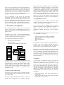
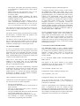
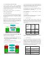
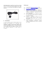
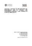
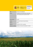
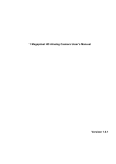
Wireless module of localization and control for security
J. Luna Rodríguez1, V. Barranco López2 , D. Bullejos Martín2 and A. Sabariego Hernández1
1
Department of Architecture of computers, Electronic technology and Electronic
2
Department of Electrical Engineering
E.P.S., Córdoba University
C/ María Virgen y Madre s/n 14071 Córdoba (Spain)
Phone/Fax number:+0034 957 218363, e-mail: [email protected], [email protected], [email protected],
[email protected]
Key words
M2M be a mixture of different techniques (processing,
electronics and communications). Automotion, control
and management of fleets, tracking systems, security and
emergency systems are among the most fruitful sectors.
All of them need the combination of two complementary
systems, GPS and GSM/GPRS. They are advanced
programmable systems which require special features of
connectivity and transmission speed.
Solar energy, photovoltaic, GPS, anti-theft
2.
1. Introduction
The main objective of this Project is to develop a
complete system based on the combination of GPS and
GSM/GPRS systems applied to the localization and
watching for the security of solar panels outside the
cities, as well as an alarm system (in case of stealing or
failure) through a mobile phone.
Abstract.
Solar parks and photovoltaic solar centrals are
proliferating to produce more electric power. They are generally
placed far away from city centres; consequently thefts of the
panels occur quite commonly. We introduce an anti-theft
system: a GPS programme which could detect the change of
placement of a panel and track its position.
Nowadays, the rapid growing of communication systems
through GPS and mobile phone systems, joined to the
boom of renewable energies (due to the decrease of
traditional energy sources and the pollution they cause),
make possible the joint of both markets with the goal of
obtaining new applications, such as the control, tracking
down and security of the fleets. Solar energy (and
specifically photovoltaic solar energy in our case) is in a
continuous rise, and the companies making use of this
type of energy in their industrial processes are growing,
saving quite a lot of money in the long term. Its
continuous evolution makes them more and more
accessible, not only for companies but also for people.
Solar photovoltaic energy is an economic reliable
solution which can be adapted to many applications,
having interesting features such as low maintenance and
failure rate.
In the communication market, the term M2M is used to
refer to the systems allowing the machines to
communicate through company information systems
either with other machines (M2M stands for Machine-toMachine in English), or with people through the mobile
(M2M also stands for Machine-to-Mobile) for the
bidirectional transfer of data in real time. M2M solutions
are designed to increase productivity, use and reduction
of costs and time, to improve processes, service to the
client and, above all, they mean a new way of doing
things.
The combination of different technologies in a single
device (data capture, transfer and processing) makes
Objetive
The system tests the state of a signal which will report
the owner on the position of the panel. If it is not, the
system will calculate its position through the GPS
module and will report (through an alarm system by SMS
to the mobile phone of the owner) on the exact position
of the fleet, to be able to begin the process of its
recovery. Each solar panel will integrate a complete
system (GPS module, GSM/GPRS module, failure
detection module, GPS antenna, GSM/GPRS antenna and
electric supply module) which will be integrated in its
structure to avoid detachment.
The main objective of this project, as has been stated
before, is the fleet of solar panels which could need to be
repaired, substituted or recovered from burglary, due to
the need of placing companies in industrial floor far away
from cities, and also to the high cost of the devices for
the obtaining and transformation of photovoltaic energy.
This makes installations expensive, as well as meaning
an additional cost to substitute the lost elements by new
ones, making a constant problem for the affected
companies. Thanks to GPS technology, it now is possible
to solve the problem. We can always know the
localization of the devices and report, through
GSM/GPRS to the mobile of the owner, on either a
possible failure occurred or on a problem with its
localization.
This is not only a solution to the security problem, but it
is also a really efficient system to detect burglary and
malfunction, with the resulting recovery by the owner. It
will also mean a loose of contracts with companies
devoted to the recovery of stolen objects, because it is
now the owner who can recover his/her panels without
paying any money or instalments for the service.
For the realization of this project we need GPS
instruments (for the tracking and localization) and
GSM/GPRS instruments (for sending information). Some
years ago, the main problem found to develop this type of
industrial applications was the high prices of such
devices, which have been lowered nowadays because of
the increase in the number of manufacturers and models.
3. Description of the application
Each solar panel (placed at the end of a frame) will
integrate a GPS module, a GSM/GPRS module (both of
them in the same device for this Project) and an electric
supply system.
The brain of the system is the combined technology
GSM/GPS module for the acquisition and sending of data
(for this case) the placement of the solar panel.
This application can fulfil three main tasks:
- Data supervision and control.
- Data acquisition.
- Generation and sending of an alarm signal.
GPS Satellites
seen
Satellite 1
Satellite 2
Satellite 3
Satellite 4
Programming
Interface
Data acquisition and transmission
(Module GSM/GPS)
Module GPS
Module GSM
Signal
reception
SMS
sending
Satellite 5
Satellite 6
Satellite 7
Satellite 8
Reception equipment
(mobile)
panel through its corresponding circuit. If it is stolen, the
module will be supplied by the battery for only a limited
amount of time. To supply the module a 3.8 volt current
is needed in an operation range 3.4-4.2 volt. Following
the above described procedure, a circuit will be needed to
charge the battery supplying the module. Such circuit
needs a converter continuous-current continuous-current
(cc/cc), which adapts the panel current (between 29.48 v
and 35.5 v) to the 12 volt required by the charger, and
thus charges the battery to supply 3.8 volt to the module.
3.1.1. Regulation of current
An electronic converter is needed to adjust the output
current to a constant value according to the input current
available and the output current needed.
Not many converters are designed which use general
purpose components. Instead, integrated converters are
found, so the time and number of components is
dramatically reduced, thus having a more economic
circuit.
The main features we must have into account to choose
cc/cc integrated converters are:
- Input and output current: reducer or amplifier.
- Margin of input current: the bigger, the better.
- Output current.
- Range of temperature.
- Size.
For this work we have selected a PCB integrated cc/cc
converter. It is a four terminal converter that gives a
constant output 12 volt current needed to supply the
charge circuit. It is quite small because of its design.
Depending on the model and brand of the solar panel
used, the current it gives is different (between 29.48 and
35.5 volt, following the technical specifications of the
manufacturer). According to these data, we have chosen a
converter that allows a wide margin of input current, 1872 volt, (± 5), enough for different panels with an output
current of 250 mA.
Data screening
The data acquisition and transmission module, that is, the
GSM/GPS module, is the most important part of this
system because it controls and sends the alarm signal.
Broadly speaking, this module takes the position data
from the GPS receptor (latitude, altitude, length, number
of satellites seen, etc.) and then it collects them in a
message to be sent.
3.1. Electric supply of the system
The electric supply of the system is obtained from the
own solar panel to which it is attached; we have chosen a
type called ‘online’.
This type of supply is described as follows: a battery is
placed, which is supplied by the voltage of the solar
3.1.2. Battery
As it has been said before, the supply current for the
module must be 3.8 volt in a 3.4-4.2 margin. We got
them with a Lithium-Ion battery (Li-Ion) of 3.7 volt,
whose use is set by the module itself. According to the
user’s manual, the battery must correspond to this type,
rejecting other types (Ni-Cd, Ni-MH, etc.) because they
can entail overvoltage of the module and its consequent
damage. In addition, lithium batteries are the most
recommendable ones because they have the following
advantages:
-
High energy density. They keep a big charge per
volume unity.
Light weight. With the same volume, they are lighter
than Ni-MH o Ni-Cd batteries.
-
-
-
Thin objects. This makes them especially interesting
to be integrated in portable devices, which require
thin objects.
Higher current per cell. Each battery gives 3.7 volt,
the same as three Ni-Cd batteries (1.2 V each).
No memory effect.
Linear discharge. During discharge, the battery
voltage remains the same, which avoids the need of
inefficient regulator circuits.
Low self-discharge rate. When a battery is kept, it
slowly self-discharges though it is unused. For NiMH batteries such self-discharge can be 20% per
year. For Li-Ion batteries it is only 6% (± 0,2% daily).
This manual also indicates that the battery must have at
least 500 mAh to stand current peaks of 2 A. We have
chosen a 1300 mAh.
The battery must be linearly placed between the module
and the battery, a Schottky diode and, parallel to the
diode, a tantalum condenser of 1µF.
The diode is used to avoid the possible inverse current,
that is, to help the current circulate in one way, from the
battery to the module and not the other way round. The
condenser is needed to get a constant input current.
- Programming language, preferably high level.
According to all these selection criteria, we have chosen
the GM862-GPS module, Telit brand, with its own
development system, Telit Evaluation Kit (EVK2) for the
programming phase. It is a module which offers an easy
solution to be implemented, with a wide range of
temperatures, antenna connectors, SIM built-in interface
which is needed for the sending and reception of SMS,
13 input-output general purpose ports, and a digital
analogical converter. It is especially oriented for
telemetric applications of tracking and security. It also
includes a Python interpreter, which allows the handling
of the equipment internally with an application written in
the same language. It includes an additional 3MB nonvolatile memory and 1.5 MB RAM
We first considered the idea of using a GPS module with
other GSM/GPRS, together with a microcontroller in
charge of the control and burglary report, but we finally
found a wide range of built-in modules in the market,
which offer a more compact solution and which are
cheaper than years ago, due to the high growing of these
technologies in the security sector, as well as the tracking
and emergency systems.
3.2.1. Features of the GSM/GPRS module
3.2. GMS/GPS Module
It is the set of elements (software and hardware) which
allow to determine (in our case) the position of our stolen
panel and to report on its placement. We need, on the one
hand, a receiver device through GPS and, on the other
hand, a GSM-GPRS modem to facilitate the sending and
reception of sms and data to the owner.
There exist a wide variety of GPS and GSM/GPRS
modules in the market. They can be found either
separately or both integrated into the same device. This
last type is called built-in module.
The possibility to find both complementary integrated
technologies has been crucial for our choice, due to the
small space requirement. We have chosen a built-in
module because it is cheaper than buying independent
technologies. In addition, we have noted its availability
and variety in the market nowadays.
The GSM/GPRS modem is only a cellular terminal
similar to a mobile, lacking the keyboard and the display.
So, it needs to be registered by a phone operator that will
facilitate a number (either contract or card) and the
number of a Message Centre for the reception and
sending of SMS.
It is a four-band GPRS modem (850/900/1800/1900
MHz), class 10.
The majority of the control software (or the modem
commandos) fit to the Hayes norms, AT+ commandos
that have the following general format:
AT+Commando = Datum <CR> <LF>
Configuration writing / sending of messages, and
AT+Commando? <CR> <LF>
Other considerations are the following:
Configuration reading / states of the modem.
Dimensions, because the application requires a reduced
size, the same as the rest of the components.
As it can be seen, the goal of the transmission is
identified by the characters <CR> y <LF>, excepting for
some special commandos.
-
The type of encapsulation.
The sensitivity of the GPS receiver, which must be as
high as possible.
The type of chipset built-in the receiver, crucial for
the reception of the satellites.
The type of GSM bands (dual, three-band, four-band)
and its speed (GPRS class 9, class 10, etc.).
The option to have an internal memory for our code.
The possibility to include a development system
which makes programming easier and faster.
There are a great number of AT commandos for different
goals: to programme the port, the sending of SMS
messages, the management of messages memory inside
the modem card, the establishment of voice calls, or even
the possibility of sending and receiving faxes and emails,
though these are not necessary for our application.
3.2.2. Characteristics of the GPS module
The GPS module includes a single chip SIRFstarIII
receiver, the most potent of the market, with 20 channels,
a high sensitivity for reception (-159 dBm), and a
medium consumption of 70 mA per operation (including
the GPS antenna consumption).
Such module is GSM controlled, AT commandos or
NMEA command statements.
As it can be seen in this case, the interpreter fulfils the
task of the external microcontroller. This communicates
with the module through a serial virtual port by AT
commandos, instead of using the physical port.
The disadvantage found in this configuration is that it is
not practical for applications that need large
programming and, so on, long scripts.
Only a 3 MB memory is available, though it is enough
for our application.
3.2.3. Python Interpreter
3.2.4. Antennas
As it was said above, the module includes an interpreter
that allows the internal control of the modem, by writing
the control application directly in a high-level language
called Python.
The incorporation of the internal interpreter is especially
directed to low-complexity applications, which could be
fulfilled by a small micro-controller that handles the
input and output pins, as well as the module itself
through the serial port by AT commandos.
The following can be a diagram of its configuration:
The module has got two antenna connectors, a GSM and
a GPS one, which are described below.
•
GSM Antenna
To allow the GSM module working properly and
realizing its functions, an antenna needs to be attached,
which allows its registration in the operator’s net. The
antenna facilitated by the manufacturer has the following
characteristics:
Frequency
Range
GSM900
DCS1800
PCS1900
GSM900
DCS1800/
PCS1900
Polarization Lineal
50 ohm
Impedance
1W
Gain
To eliminate the external controller and make the
operation sequence programming easier inside the
modules, the following is included:
- The interpreter core Python script. Script means the
small programmes made in such language.
- 3 MB non-volatile memory (Flash ROM) for data and
programmer script.
- 1.5 RAM used by the Python interpreter.
The diagram corresponding to such configuration will be:
880 - 960
MHz
1710 - 1880
MHz
1850
1990 MHz
0 ~ 0.5 dBi
0.5 ~ 1 dBi
4 max.
-40 ~ 85 ºC
This is a three-band antenna for PCB with an MMCX
connector, specific for mobile applications.
•
GPS Antenna
For a better performance, the GPS receiver needs an
antenna with the specifications found in the user’s
manual. There are many manufacturers that allow
antennas with different filtering options, gain levels, type
of connectors, level of output impedance, cable length
and assembly options. Taking into account such variety,
the manufacturer of the module recommends an antenna
with the following electrical specifications:
Range
of
frequency
1575,42 MHz (GPS L1)
Current
Tension
Gain
3.4 - 4.2 VDC
Impedance
Electricity
consumption
50 Ω
3 dBi > Gain > 1,5 dBi
20 mA max.
The antenna used is a compact one. It has a 5 m long
cable and magnetic assembly. The supply tension ranges
over 3 to 5 volt (in the specified margin) with 5 ohms
impedance. It is connected to the module by an MMCX
connector.
References
[1]
[2]
[3]
[4]
[5]
[6]
4. Conclusions
A remote-controlled system through mobile for the
checking and localization of a solar-plates fleet
controlled by GPS has been presented in this paper. The
possibility of finding a device in the market which
combines GSM/GPRS technology with GPS, functioning
in one module, allows the company to reduce costs for
those industrial applications in which money is
considered.
Solardelvalle. http://www.solvalle.es/ . 2007.
Arrow-Iberia Electronica. Módulos GM862-GPS.
http://www.arrowiberia.com/ . 2007.
Bustos, Eduardo J. et al. WLAN y Bluetooth: el
despegue de las comunicaciones inalámbricas
locales y su integración con las redes móviles.
Telefónica Investigación y Desarrollo, pp 83-98.
Nº 25 · Marzo 2002.
Anon. Increased interest in WiMAX will impact
the cellular M2M market. Microwave Journal 50
(10): 52-52. Oct 2007.
Gasieniec L, Kranakis E, Pelc A, et al.
Deterministic M2M multicast in radio networks.
Theoretical Computer Science 362 (1-3): 196-206.
Oct 11 2006.
Sadoun B, Al-Bayari O. Location based services
using
geographical
information
systems.
Computer Communications 30 (16): 3154-3160.
Nov 3 2007.