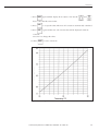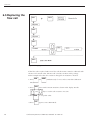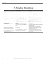
1
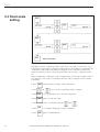
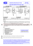
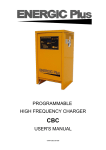
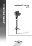
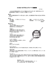
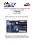
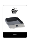
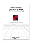
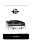
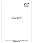
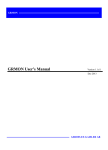
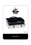
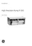
A
M
E
R
S
H
A
M
B
I
O
S
C
I
E
Conductivity Monitor
CM-P
User Manual
18-1101-29
Edition AC
Conductivity Monitor CM-P User Manual 18-1101-29
N
C
E
S
Conductivity Monitor CM-P User Manual 18-1101-29
Contents
1. Introduction ........................................................................................................ 3
2. General Description ............................................................................................ 4
2.1 Principle of operation ................................................................................. 9
2.2 Transmitter................................................................................................. 5
2.2.1 Front panel ...................................................................................... 5
2.3 Flow cell ............................................................................................. 6
3. Technical Specifications ...................................................................................... 7
4. Installation .......................................................................................................... 8
4.1 Connection of the flow cell ......................................................................... 8
4.2 Transmitter set up ...................................................................................... 8
5. Operation .......................................................................................................... 10
5.1 Setting the scale with buffers ..................................................................... 10
5.2 Menu ........................................................................................................ 11
5.3 Fixed scale setting ...................................................................................... 12
5.4 Temperature compensation ....................................................................... 13
5.5 Summary of commands in menu ............................................................... 15
6. Maintenance ...................................................................................................... 16
6.1 Cleaning the flow cell ................................................................................ 16
6.2 Calibration mode ...................................................................................... 16
6.3 Calibration of the temperature sensor ....................................................... 17
6.4 Calibration of the cell constant .................................................................. 18
6.5 Replacing the flow cell .............................................................................. 20
6.6 Summary of commarnds in Calibration Mode ........................................... 21
7. Trouble Shooting ............................................................................................... 22
8. Accessories ......................................................................................................... 23
Conductivity Monitor CM-P User Manual 18-1101-29
1
2
Conductivity Monitor CM-P User Manual 18-1101-29
1. Introduction
1. Introduction
The Amersham Biosciences Conductivity Monitor, CM-P, is a high quality, high
precision on-line monitor for conductivity measurements and gradient determination
in liquid chromatography applications.
The monitor consist of two units, the flow cell and the transmitter. The flow cell
contains the titanium electrodes used for conductivity measurement as well as a
temperature sensor. The small size of the flow call allows it to be posiotioned
anywhere in the liquid path, provided that the pressure specification for the cell is not
exceeded.
The transmitter carries the six programming keys for the monitor. An easy to read 16
digit alphanumeric display shows the conductivity measured in Siemens/cm (mS/cm).
The transmitter communicates with the UNICORN controller over a serial interface
using optomux protocol. Through this communication the conductivity measurement
is transmitted to UNICORN. The electrical outputs are only used for a possible
optional recorder.
The monitor has a very large dynamic range from 0.001 mS/cm to 999.9 mS/cm and
therefore suitable for a wide range of applications, ranging from reversed phase to
hydrophobic interaction chromatography. A unique design of the electronics is the
microprocessor control of frequency variations within the working range. This gives
excellent linetary and eliminates the need for range settings.
Conductivity Monitor CM-P User Manual 18-1101-29
3
2. General description
2. General description
2.1 Principle of
operation
Fig. 1. The flow cell
The flow cell has two cylindrical shaped titanium electrodes positioned in the flow
path of the cell. An alternating voltage is applied between the electrodes and the
resulting current is measured and used to calculate the conductivity of the eluent. The
microprocessor controls the AC frequency and automatically increases it with
increasing conductivity between 50 Hz and 50 kHz. This unique design gives maximum lineatary and true conductivity values.
The monitor measures conductivity over the complete working range. No range
settings are required. However, to obtain a suitable output signal to the recorder and
to get a relative conductivity value, it is possible to set a O to 100% range. This can
be done with the buffers used or by selecting any fixed range between 0.001 mS/cm
and 999.9 mS/cm.
The monitor displays the conductivity in mS. The conductivity is automatically
calculated by multiplaying the measured conductance by the flow cells cell constant.
The cell constant is pre-calibrated on delivery but can be measured with a separate
calibration procedure.
One of the electrodes has a small temperature sensor for measuring the temperature
of the eluent in the flow path. Temperature variations influence the conductivity and
in some applications, when highly precise conductivity values are required. it is
possilble to program a temperature compensation factor that recalucates the
conductivity to a set reference temperature.
4
Conductivity Monitor CM-P User Manual 18-1101-29
2. General description
2.2 Transmitter
The microprocessor-based transmitter communicates with the UNICORN controller
over a serial interface using the optomux communication protocol. The transmitter
fits into a 19” industry standard rack.
2.1.1 Front panel
The front panel consists of an alphanumerical LCD display window and a keyboard
with six membrane keys.
Fig. 2. The front panel
Display
mS
%
Displays the actual conductivity value in mS, (mS/cm) and
the relative conductivity in %.
Keyboard
This key sets the 0% conductivity level eith the low coductivity buffer.
The set 0% keys is pressed for 1 second while the low conductivity
buffer is pumped through or injected into the flow cell. The voltage
output to the recorderis set to 0 V for the measured conductivity.
This key sets the 100% conductivity level with the high conductivity
buffer. The set 100% key is pressed for 1 second while the high
conductivity buffer is pumped through or injected into the flow cell. The
voltage output to the recorder is set to 1 V for the measured
conductivity.
The menu is used to step between the functions below:
1.
Set 100%. With this function any fixed conductivity value in mS/
cm can be set for the 100% level.
2.
Set 0%. With this function any fixed conductivity value in mS/cm
can be set for the 0% value.
Conductivity Monitor CM-P User Manual 18-1101-29
5
2. General description
3.
4.
Set TC. A temperature compensation factor for the conductivity
can be set. This can be necessary for high precision
measurements. The temperature compensation factor is expressed
in percentage increase of conductivity per oC increase in
temerature. If the temperature compensation factor is unknown, a
general approximate value for many common salt buffers used in
chromatography applications.
When the temperature compensation is set to 0, it is inactive.
Set TRcf. The temperature compensation factor must be realted
to and adjusted to a set reference temperature in range 4-40 oC.
The ”arrow down” and ”arrow up” keys are used to select
numerical values in the menu settings. The keys can be held down
for a faster scroll.
The enter key is used to enter programmed values and to exit to Run
Mode.
2.3 Flow cell
6
The flow cell exterior is made of PEEK and the interior between the titanium
electrodes of flouroplastics. Both ends of the flow cell have female M6 fittings. The
signal cable which connects to the control unit has a 9 pole DSUB connector.
Conductivity
6
Monitor CM-P User Manual 18-1101-29
3. Technical Specifications
3. Technical
Specifications
Operating mode
Sensitivity range
Accuracy
Auto range conductivity in mS/cm
0.001 mS/cm-999.9 mS/cm
2% full scale calibrated range or
0.01 mS/cm whichever is greater in the
range 0.001-300 mS/cm
Noise
Flow rate range
Analogue output
Power supply
Operating conditions
Power consumption
0.5% full scale calibrated range
0-100 ml/min
0-1 V or 4-20 mA
24 V DC
4-40 oC, 20-95% RH, Atmospheric
pressure 840-1060 mb, (84-106 kPa)
2W
Flow cell
Type
Cell constant
Internal volume
Maximum operating pressure
Wetted parts
Fittings
Flow through
50 cm-1, nominal
14 III
5 MPa, 50 bar, 750 psi
Fluoroplastics, titanium
M-6 (6 mm metric)
Conductivity Monitor CM-P User Manual 18-1101-29
7
4. Installation
4. Installation
4.1 Connection of
the flow cell
Fig. 3. Connection of flow cell to UNICORN control box.
1.
4.2 Transmitter
Connect the signal cable from the cell to the socket ”Cond” on the UNICORN
Control box.
The transmitter is correctly set up on delivery of the system. Set-up parameters are
saved in non-volatile memory, and do not need to be changed.
Make a note of the optomux communication parameters for your transmitter. If a
faulty transmitter is replaced with a new unit, the optomux parameters for the new
unit should be set to the same values as for the old transmitter.
To set parameters, start the monitor in start-up mode by pressing and simultaneosly
as the power is switched on, and keeping the buttons pressed for about 5 seconds.
The display is dark for 5 seconds, then shows the program version for 5 seconds
followed by the current optomux address, e.g.:
Optomux
addr 002
The addres is a number between 0 and 255. Refer to your system documetation for
the correct address. Press the arrow keys to change the address until the correct value
is displayed, then press enter. The display now shows the communication rate, e.g.:
Baudrate
38400
Permissible baud rates are 1200, 2400, 4800, 9600, 19200 and 38400. Normally
38 400 is used. the correct setting is determinded by the optopux
8
Conductivity Monitor CM-P User Manual 18-1101-29
4. Installation
communication port setting in the controller. Use the arrow keys to choose the
correct communication baud rate, then press enter. The display now shows the
accumulated operation time and the number of starts, e.g.:
00021 h
0003 st
Press enter to continue.
Conductivity Monitor CM-P User Manual 18-1101-29
9
5. Operation
5. Operation
5.1 Setting the
with buffer
Press 1 second
Press 1 second
Fig. 4. Setting the scale.
When the conductivity monitor is switched on, it is in Run Mode and will display the
measured conductivity. To set the output range to the recorder, the conductivity levels
100% and 0% can easily be set with the high and low conductivity buffers used for
the gradient
1.
Start the flow in the system with the high conductivity buffer.
2.
When the conductivity reading stabilises, press
3.
Change to the low conductivity buffer and when the new conductivity level is
stable, press
for 1 second.
for 1 second.
The monitor is now ready for use
The setting of the 100%, and 0%, levels will remain in the transmitter until a
new scale is set.
10
Conductivity Monitor CM-P User Manual 18-1101-29
5. Operation
5.2 Menu
Fig. 5 Menu overview.
With the menu key, more advanced functions can be programmed, such as setting the
conductivity to any range independent of the buffers and temperature compensation
of the conductivity to reference temperature. The menu key is also used to step
between the functions.
Conductivity Monitor CM-P User Manual 18-1101-29
11
5. Operation
5.3 Fixed scale
setting
Fig. 6. Fixed scale setting
The 100% and 0% conductivity values can be set to any value of your choice, e.g. to
extend the recorder full scale deflection and baseline to be slightly over and under the
conductivity of the buffers. In addition it might be easier to read the conductivity
values for specific peaks in a chromatogram if the scale is in tens or hundred of mS/
cm.
In this example the conductivity scale is changed from a previously set 100% value of
125 mS/cm to a new value of 150 mS/cm. the 0% value is changed from 3.5 mS/cm
to 0.00 mS.
1. Press
2. Use
, the previously set 100% value is displayed.
and
keys to set the conductivity value to 150 mS.
3. Press
to accept the value. Set to 150 mS is displayed.
4. Press
again to set the 0% value.
5. Set the value for 0% to 0.00 mS using the
12
and
6. Press
to accept the setting. Set to 0 mS is displayed.
7. Press
again to exit Run Mode.
Conductivity Monitor CM-P User Manual 18-1101-29
5. Operation
5.4 Temperature
compensation
Fig. 7 Temperature compensation setting.
Temperature variations may influence conductivity. If high accuracy in the specific
conductivity is required, a temperature compenstion factor can be programmed
togheter with a reference temperature. All conductivity values will then automatically
be converted to the set reference temperature. If the temperature coefficient is
unknown a recommended average temperature compenstion factor of 2%
(conductivity increase in percentage per oC) can be used for most common salts used
in liquid chromatography applications.
When the temperature compensation is set to 0, this function is inactive.
Conductivity Monitor CM-P User Manual 18-1101-29
13
5. Operation
In the example below the temperature compensation factor is changed from a
previosly set value of 2.1% to a new value of 2.0%. The reference temperture is
change from 23.5 oC to 25.0 oC.
1. Press
three times until the Set TC menu is displayed.
2. Set the value of the temperature compensation factor to 2.0% using the
and
keys.
3. Press
to accept the value. Set to 2.0% is displayed.
4. Press
to set the temperature to which the conductivity values should be
corrected. Tref 23.5 oC is displayed. Use the
temperature to 25.0oC.
14
5. Press
to accept the temperature.
6. Press
again to exit to Run Mode.
Conductivity Monitor CM-P User Manual 18-1101-29
and
keys to set the
5. Operation
5.5 Summary of
commands in
menu
Fig. 8. Summary of commands.
Conductivity Monitor CM-P User Manual 18-1101-29
15
6. Maintenance
6. Maintenance
The Conductivity Monitor requires very little maintenance if precautions are taken
to protect the flow cell.
Note: When the flow cell is not in use, rinse the cell with de-ionised water, do not
leave buffers to dry in the cell. When the monitor is stored for a longer period
of time, fill it with 20% ethanol.
6.1 Cleaning the
flow cell
The flow cell is designed to withstand cleaning-in-place with 1 M NaOH.
6.2 Calibration
Mode
Fig. 9. Calibration Mode menu
16
Conductivity Monitor CM-P User Manual 18-1101-29
6. Maintenance
6.3 Calibration
of the temperature
sensor
Fig. 10. Calibration of the temperature sensor.
The cell constant and the temperature sensor can be calibrated in the monitor
calibration mode. New monitors are factory calibrated and it is not recommended to
change these values.
Calibration of the temperature sensor is only necessary if the monitor is used to
determine absolute conductivity with high accurary.
In the example below the temperature is adjusted from 23.5 oC to the measured
temperature of 25.0 oC.
1. Place the flow cell together with a precision thermometer inside a box or beaker to
ensure that they are not exposed to draft. Leave them for 15 minutes to let the
temperature stabilise.
2. Read the temperature on the thermometer.
3. Press
and
simultaneosly for 2 seconds to enter the Calibration
Mode.
4. The display shows Adjust temp. 23.5 oC. Use the
and
keys to set
the temperature on the control unit to 25.0 oC the temperature shown on the
thermometer.
5. Press
to accept the setting.
6. Press
again to exit the Calibration Mode.
Conductivity Monitor CM-P User Manual 18-1101-29
17
6. Maintenance
6.4 Calibration
of the cell
constant
Fig. 11. Calibration of cell constant.
Normally it is not necessary to calibrate the flow cell as it is pre-calibrated on delivery. Calibration of the flow cell is only necessary when the monitor is to be used to
determine specific conductivity with high accuracy.
In the example below the cell constant is changed by setting the conductivity value of
a calibration buffer to theoretical value at an exact temperature.
1. Prepare a calibration solution of 1.00 M NaCl, 58.44 g/l.
2. Fill the flow cell with the calibration solution, either via a syringe or by pumping at
least 15 ml through the cell.
3. Stop the flow and wait for 15 minutes, until the temperature is constant in the
range 20-30 oC.
4. Read the conductivity value displayed.
Note: Make sure the Temperature Compensation is off.
5. Press
and
simultaneously for 2 seconds to enter the Calibration
Mode.
6. Read the temperature in the Adj. temp menu. Compare the erlier displayed
conductivity value with the theoretical value from the graph below, at the temperature of the calibration solution. If the theoretical and the displayed value correspond
no further action is required. If the values duffer proceed as outlined below.
18
Conductivity Monitor CM-P User Manual 18-1101-29
6. Maintenance
7. Press
again until the display shows adjust cond. Use the
and
keys to enter the theoretical value.
8. Press
to accept the value. The new cell constant is automatically calculated.
9. Press
again and the new cell constant value will be displayed in the me
Constant.
Note: Do not change this value.
10. Press
to exit to run mode.
Fig. 12. Conductivity of 1 M NaCI at 20-30 oC.
Conductivity Monitor CM-P User Manual 18-1101-29
19
6. Maintenance
6.5 Replacing the
flow cell
Fig. 13. Changing the cell constant.
If the flow cell is replaced with a new flow cell, the monitor must be calibrated with
the new cell constant value. The new cell constant is written on the package.
In the example below the cell constant is changed from 43.0/cm to 41.0/cm.
1. Press
and
simultaneously for 2 seconds to enter the Calibration
Mode.
2. Press
twice until Constant 43.0/cm is shown in the display. Use the
and
20
keys to set the cell constant to 41.o/cm.
3. Press
to accept the value.
4. Press
again to exit to Run Mode.
Conductivity Monitor CM-P User Manual 18-1101-29
6. Maintenance
6.6 Summary of
commands in
Calibration
Mode
Fig. 14. Summary of commands.
Conductivity Monitor CM-P User Manual 18-1101-29
21
7. Trouble Shooting
7. Trouble Shooting
Problem
Possible cause
Remedy
Baseline drift or noisy signal
monitor
Air in flow cell
Use a flow restrictor after the conductivity
flow cell
Check for leaking tubing connections
Clean flow cell according to procedure
Maintenance 6.1
Equilibrate and/or regenerate column
Turn the flow cell so the end with the
screws is electrode is influenced by
facing the other instrument
Set the temperature compensation factor
to O
None required
Dirty flow cell
described in
The absolute conductivity value
is wrong
Ghost peaks appear in the
gradient profile
Charged sample detected (e.g.
protein)
Air bubbles passing through flow
cell
Conductivity measurements
with the same buffer appear to
The monitor does not respond
to conductivity change
22
Column not equilibrated or dirty
The electrical grounding of the
electrode is influenced by another
instrument
Temperature compensation is on
Dirty flow cell
Room temperature has decreased
Faulty flow cell or transmitter
Use a flow restrictor after the conductivity
monitor flow cell
Check for loose tubing connections
Clean flow cell according to procedure
described in section 6.1
Use temperature compensation factor
Call a Amersham Biosciences service
representative
Conductivity Monitor CM-P User Manual 18-1101-29
8. Accessories
8. Accessories
Designation
Code No.
Conductivity Flow Cell
19-1515-15
Trademarks
Amersham and Amersham Biosciences are trademarks of Amersham plc.
© Amersham Biosciences AB 2000 – All rights reserved
All goods and services are sold subject to the terms and conditions of sale of the
company within the Amersham Biosciences group which supplies them.
A copy of these terms and conditions is available on request.
Amersham Biosciences AB
Björkgatan 30, SE-751 84 Uppsala
Sweden
Amersham Biosciences UK Limited
Amersham Place, Little Chalfont
Buckinghamshire, HP7 9NA
England
Amersham Biosciences Inc
800 Centennial Avenue, P.O. Box 1327
Piscataway, New Jersey 08855
USA
Amersham Biosciences Europe GmbH
Postfach 5480
D-79021 Freiburg
Germany
Conductivity Monitor CM-P User Manual 18-1101-29
23
Printed in Sweden by TK i Uppsala AB, 2003
Conductivity Monitor CM-P User Manual 18-1101-29
Conductivity Monitor CM-P User Manual 18-1101-29