1
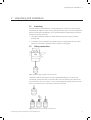
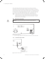
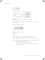
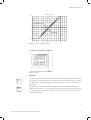
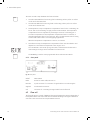
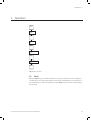
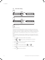
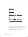
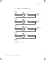
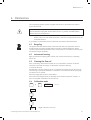
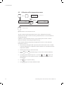
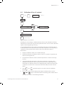
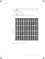
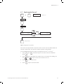
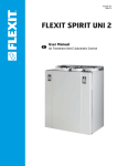
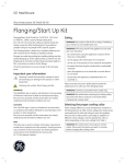
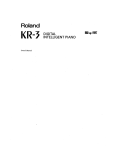
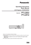
GE Healthcare
Conductivity Montior
User Manual
Important user information
All users must read this entire manual to fully understand the
safe use of Conductivity monitor.
WARNING!
The WARNING! sign highlights instructions that must
be followed to avoid personal injury. It is important
not to proceed until all stated conditions are met and
clearly understood.
CAUTION!
The Caution! sign highlights instructions that must be followed
to avoid damage to the product or other equipment. It is
important not to proceed until all stated conditions are met and
clearly understood.
Note
The Note sign is used to indicate information important for
trouble-free and optimal use of the product.
CE Certifying
This product meets the requirements of applicable CE-directives.
A copy of the corresponding Declaration of Conformity is
available on request.
The CE symbol and corresponding declaration of conformity, is
valid for the instrument when it is:
– used as a stand-alone unit, or
– connected to other CE-marked GE Healthcare instruments, or
– connected to other products recommended or described in
this manual, and
– used in the same state as it was delivered from GE Healthcare
except for alterations described in this manual.
WARNING!
This is a Class A product. In a domestic environment this product
may cause radio interference in which case the user may be
required to take adequate measures.
Recycling
This symbol indicates that the waste of electrical
and electronic equipment must not be disposed
as unsorted municipal waste and must be
collected separately. Please contact an authorized
representative of the manufacturer for information
concerning the decommissioning of equipment.
WARNING!
This is a class A product. In a domestic environment, this
product may cause radio interference, in which case the user
may be required to take adequate measures.
Contents
Contents
1
Introduction
2
Unpacking and Installation
2.1 Unpacking............................................................................................................................................ 9
2.2 Tubing connections......................................................................................................................... 9
2.3 Electrical connections................................................................................................................. 10
2.3.1 Connection of the flow cell 2.3 Electrical connections.................................................. 10
2.3.2 Connection of the recorder........................................................................................................ 10
2.3.3 Connection of the gradient signal to
LCC-501 Plus and to the Recorder.......................................................................................... 11
3
Getting started
3.1
Setting the scale with buffers.................................................................................................. 13
4
General description
4.1 Principle of operation.................................................................................................................. 15
4.2 Control Unit...................................................................................................................................... 16
4.2.1 Front panel........................................................................................................................................ 16
4.2.2.Rear panel......................................................................................................................................... 18
4.3 Flow cell............................................................................................................................................. 18
5
Operation
5.1
5.2
5.3
5.4
Menu.................................................................................................................................................... 19
Fixed scale setting........................................................................................................................ 20
Temperature compensation..................................................................................................... 21
Summary of commands in menu......................................................................................... 23
6
Maintenance
6.1
6.2
6.3
6.4
6.5
6.6
6.7
6.8
7
Trouble Shooting
7.1
8
Technical Specifications
9
Accessories and Spare Parts
Recycling........................................................................................................................................... 25
Instrument housing...................................................................................................................... 25
Cleaning the flow cell.................................................................................................................. 25
Calibration mode........................................................................................................................... 25
Calibration of the temperature sensor................................................................................ 26
Calibration of the cell constant............................................................................................... 27
Replacing the flow cell................................................................................................................ 29
Summary of commands in Calibration Mode................................................................. 30
Recycling........................................................................................................................................... 31
Index
Conductivity Monitor User Manual 19-1139-65 Edition AF
Contents
Conductivity Monitor User Manual 19-1139-65 Edition AF
Introduction 1
1 Introduction
Important! Conductivity Monitor is intended for laboratory use only, not for clinical
or in vitro use, or for diagnostic purposes.
The GE Healthcare Conductivity Monitor, Code No. 18-1500-00, is a high quality, high
precision on-line monitor for conductivity measurements and gradient determination in
liquid chromatography applications.
The monitor consists of two units, the flow cell and the control unit. The flow cell contains
the titanium electrodes used for conductivity measurement as well as a temperature
sensor. The small size of the flow cell allows it to be positioned anywhere in the liquid
path, provided that the pressure specification for the cell is not exceeded.
The control unit carries the six programming keys for the monitor. An easy to read
32 digit alphanumeric display shows the conductivity measured in Siemens/cm
(mS/cm or µS/cm) and the temperature. The display also shows the relative gradient
position as a percentage of the maximum set value, as both a percentage figure and
graphically.
The monitor has a very large dynamic range from 1 µS/cm to 999.9 mS/cm and is
therefore suitable for a wide range of applications, ranging from reversed phase to
hydrophobic interaction chromatography. A unique design of the electronics is the
microprocessor control of frequency variations within the working range. This gives
excellent linearity and eliminates the need for range settings.
WARNING! No service parts inside equipment, it is not allowed to open the instrument
by the user or responsible body.
Conductivity Monitor User Manual 19-1139-65 Edition AF
1 Introduction
Conductivity Monitor User Manual 19-1139-65 Edition AF
Unpacking and installation 2
2 Unpacking and Installation
2.1
Unpacking
Carefully unpack the GE Healthcare Conductivity Monitor. Check the contents against
the packing list supplied. Inspect for any damage that may have occurred during transit.
Report any damage immediately to your local GE Healthcare representative and to the
transport company concerned.
• The system should be installed on stable laboratory bench providing a suitable
working area.
• To maintain correct ventilation, the system requires an appropriate amount of free
space. Do not block the ventilation inlets or outlets on the system.
2.2
Tubing connections
Fig 1. Connection of the gradient monitor flow cell.
Unpack the flow cell. Connect the short pre-flanged ETFE tubing to one end of the
conductivity monitor flow cell. Connect the other end of the tubing to the outlet of the
UV monitor flow cell or the column. Connect a pre-flanged tubing with an M6 connector
(FPLC™ connector) to the conductivity monitor flow cell outlet.
Fig 2. Connection of 1/16” tubing to the flow cell.
Conductivity Monitor User Manual 19-1139-65 Edition AF
2 Unpacking and installation
If the conductivity monitor flow cell is connected to a UV monitor from another
manufacturer, use the 1/16” tubing with a Tubing Connector M6 male to connect the
flow cell to the UV monitor flow cell. Connect the M6 connector to the flow cell. Unscrew
the top of the M6 connector, push the tubing into the rubber cone, and fasten the top of
the connector. Use a suitable ”finger tight” type connector to connect the other end to
the UV monitor. Use the same tubing at the outlet of the conductivity flow cell.
Note: The flow cell does not have a recommended flow direction. However, if it is
positioned very close to another system instrument, connection should be such
that the end of the flow cell with the screws faces that instrument to minimise
influences from its ground potential.
2.3
Electrical connections
Warning! Use only mains cables delivered and approved by GE Healthcare.
2.3.1
Connection of the flow cell
Fig 3. Connection of flow cell.
1.
Connect the signal cable from the flow cell to the socket ”Cell” on the Control Unit.
2.3.2
Connection of the recorder
Fig 4. Connection of the recorder.
10
Conductivity Monitor User Manual 19-1139-65 Edition AF
Unpacking and installation 2
1.
Connect one of the supplied signal cables between the monitor and the recorder. On
the recorder end, connect one of the supplied banana plugs to the cable marked +
and the other banana plug to the cable marked –. Connect the banana plugs to the
corresponding connector on the recorder.
On the monitor end, connect the supplied green 3 Pole Female Connector to
the cable. Make sure that the polarity of the cable connections to the monitor
corresponds to those on the recorder. The third lead of the cable should be
connected to ground.
2.
Set the voltage on the recorder to 1 V.
3.
Select the appropriate mains cable and connect it to the mains socket on the
control unit.
4.
Switch on the power.
2.3.3
Connection of the gradient signal to LCC-501 Plus and
to the Recorder.
Fig 5. Connection of the gradient signal to LCC-501 Plus and to the recorder.
1.
Use the two signal cables supplied to connect the Conductivity Monitor to the
recorder and the LCC-501 Plus. Insert the ends marked + from both cables to one
banana plug. Insert the ends marked – to the other plug. Connect the banana plugs
to the corresponding contacts on the recorder.
Conductivity Monitor User Manual 19-1139-65 Edition AF
11
2 Unpacking and installation
12
2.
Connect one signal cable to the Conductivity Monitor using the green 3 Pole Female
Connector as described above (see 2.3.2).
3.
Use the second supplied 3 Pole Female Connector to connect the other cable to
the socket marked Monitor 1 or Monitor 2 on the LCC-501 Plus. Make sure that the
end marked + is connected to +, and the end marked – to – on the LCC-501 Plus.
Connect the third end to the ”A GND”.
4.
Set the monitor range to 1000 mV in the Calibration block in the LCC-501.
5.
Select the appropriate mains cable and connect it to the mains socket on the
control unit.
Conductivity Monitor User Manual 19-1139-65 Edition AF
Getting started 3
3 Getting started
set
100%
set
0%
Press 1 second
set
set
0%
Press 1 second
Setting100%
the scale
with buffers
3.1
set
100%
set
0%
Press 1 second
Press 1 second
Press 1 second
Press 1 second
Fig 6. Setting the scale.
When the conductivity monitor is switched on, it is in Run Mode and will display the
measured conductivity. To set the output range to the recorder, the conductivity levels
100% and 0% can easily be set with the high and low conductivity buffers used for the
gradient
i
set
100%
1.
Start the flow in the system with the high conductivity buffer, preferably with the
column to be used in the application installed.
2.
When the conductivity reading stabilises, press
3.
Change to the low conductivity buffer and when the new conductivity
level is stable, press
The monitor is now ready for use.
The setting of the 100%0%and 0% levels will remain in the control unit until a new
scale is set.
4.
set
Check that
the recorder is set to 1 V full scale deflection.
0%
for 1 second.
set
for 1 100%
second.
set
18-1139-65E,A2002-11 • p8
Conductivity
Monitor
UserE,Manual
19-1139-65
i
18-1139-65
A2002-11
• p8 Edition AF
i
set
0%
set
100%
18-1139-65E,A2002-11 • p8
13
3 Getting started
14
Conductivity Monitor User Manual 19-1139-65 Edition AF
General description 4
4 General description
4.1
Principle of operation
Flow
Fig 7. The flow cell.
The flow cell has two cylindrical shaped titanium electrodes positioned in the flow
path of the cell. An alternating voltage is applied between the electrodes and the
resulting current is measured and used to calculate the conductivity of the eluent. The
microprocessor controls the AC frequency and automatically increases it with increasing
conductivity between 50 Hz and 50 kHz. This unique design gives maximum linearity and
true conductivity values.
The monitor measures conductivity over the complete working range. No range settings
are required. However, to obtain a usable output signal to the recorder and to get a
relative conductivity value, it is possible to set a 0 to 100% range. This can be done with
the buffers used or by selecting any fixed range between 0 µS/cm and 999.9 mS/cm.
The monitor displays the conductivity in µS/cm or mS/cm. The conductivity is
automatically calculated by multiplying the measured conductance by the flow cells
cell constant. The cell constant is pre-calibrated on delivery but can be measured with a
separate calibration procedure.
One of the electrodes has a small temperature sensor for measuring the temperature
of the eluent in the flow path. Temperature variations influence the conductivity and in
some applications, when highly precise conductivity values are required, it is possible to
program a temperature compensation factor that recalculates the conductivity to a set
reference temperature.
Conductivity Monitor User Manual 19-1139-65 Edition AF
15
4 General description
4.2
Control Unit
4.2.1
Front panel
Fig 8. Front panel.
The front panel consists of an alphanumerical LCD display window and a keyboard with
six membrane keys.
Fig 9. Display.
Display
mS/cm
Displays the actual conductivity value in mS/cm or µS/cm.
bar graph Displays the conductivity relative to the set 100% and 0% conductivity levels.
Note: This value must not be confused with the %B value as conductivity is not directly
proportional to %B at high salt concentrations.
16
°C
Displays the actual buffer temperature in the flow cell.
%
Displays the conductivity relative to the set 100% and 0% conductivity levels in percentage.
Conductivity Monitor User Manual 19-1139-65 Edition AF
General description 4
100
100
100
0–1 M NaCl
Gradient 0–1 M Gradient
NaCl
Gradient 0–1 M NaCl
Relative conductivity
Relative conductivity
Relative conductivity
50
50
50
Gradient %B Gradient %B
Gradient %B
0
0
–10
–10
0
–10
-0.2
0 -0.2 0.2 0 0.4 0.2 0.6 0.4 0.8 0.6 1.0 0.8 1.2
-0.2
0 10. A0.2
0.6 gradient.
1.2
0.8
1.0
Fig
typical 0.4
conductivity
1.0
1.2
Fig 11. Key board.
Keyboard
set
set
0%
set 0%
0%
set
0%
This key sets the 0% conductivity level with the low conductivity buffer. The set 0% key
is pressed for 1 second while the low conductivity buffer is pumped through or injected
into the flow cell. The voltage output to the recorder is set to 0 V for the measured
conductivity.
set
set
100%
set 100%
100%
set
100%
This key sets the 100% conductivity level with the high conductivity buffer. The set
100% key is pressed for 1 second while the high conductivity buffer is pumped through
or injected into the flow cell. The voltage output to the recorder is set to 1 V for the
measured conductivity.
Conductivity Monitor User Manual 19-1139-65 Edition AF
17
menu
menumenu
4 General
description
menu
The menu is used to step between the functions below:
1.
Set scale 100%. With this function any fixed conductivity value in µS/cm or mS/cm
can be set for the 100% level.
2.
Set scale 0%. With this function any fixed conduc-tivity value in µS/cm or mS/cm
can be set for the 0% level.
3.
Set temperature comp. A temperature compensation factor for the conductivity can
be set. This can be necessary for high precision measurements. The temperature
compensation factor is expressed in percentage increase of conductivity per °C
increase in temperature. If the temperature compensation factor is unknown, a
general approximate value of 2% can be set. This is an approximate value for many
common salt buffers used in chromatography applications.
When the temperature compensation is set to 0, it is inactive.
4.
Set reference temp. The temperature compensation factor must be related to and
adjusted to a set reference temperature in the range 4–40 °C.
The ”arrow down” and ”arrow up” keys are used to selectnumerical values in the
menu settings. The keys can be held down for a faster scroll.
The ENTER key is used to enter programmed values and exit to Run Mode.
ENTER
ENTER
ENTER
4.2.2. Rear panel
ENTER
Fig 12. Rear panel.
On/Off
Mains switch.
Mains
Socket for mains cable, 100–240 V ~.
Recorder
3-pole connector for connection of signal cable to recorder using the
supplied
3-Pole Female Connector.
Cell
Connector for connecting the signal cable from the flow cell.
4.3
Flow cell
The flow cell exterior is made of PEEK and the interior between the titanium electrodes of
fluoroplastics. Both ends of the flow cell have female M6 fittings. The signal cable which
connects to the control unit has a 9 pole DSUB connector.
18
Conductivity Monitor User Manual 19-1139-65 Edition AF
5. Operation
Operation 5
5 Operation
menu
Set scale
100%
menu
Set scale
0%
menu
Set temperature
comp
menu
Set reference
temp
menu
Fig 13. Menu overview.
5.1
Menu
With the menu key, more advanced functions can be programmed, such as setting the
conductivity to any range independent of the buffers and temperature compensation of
the conductivity to a reference temperature. The menu key is also used to step between
the functions.
Conductivity Monitor User Manual 19-1139-65 Edition AF
-65E,A2002-11 • p13
19
5 Operation
menu
menu
Set scale
menu
100%
menu
Set scale
100%
menu
menu
5.2
125 mS/cm
125 mS/cm
Fixed scale setting
ENTER
100% set to
ENTER
100% set to
ENTER
menu
Set scale
100%
Set scale
125 mS/cm
ENTER
100%
125 mS/cm
Set scale
scale
Set
menu
100%
125mS/cm
mS/cm
100%
125
menu
Set scale
125 mS/cm
Set scale 100%
100%
125 mS/cm
Set scale
menu
0%
3.5 mS/cm
menu
Set scale
0%
3.5 mS/cm
menu
menu
ENTER
ENTER
menu
menu
menu
Set scale
0%
Set scale
ENTER
0%
3.5 mS/cm
Set scale
scale
ENTER
Set
Exits to Run3.5
Mode
0%
3.5
mS/cm
0%
mS/cm
ENTER
Set scale
Exits to Run 3.5
Mode
mS/cm
Set scale 0%
0%
3.5 mS/cm
ENTER
Exits to Run Mode
ENTER
Exits to Run Mode
ENTER
ENTER
Exitsto
toRun
RunMode
Mode
Exits
ENTER
Exits to Run Mode
ENTER
Exits to Run Mode
100% set to
150 mS/cm
100%set
setto
to
100%
ENTER
100% set to
ENTER
ENTER
150 mS/cm
100% set to
menu
menu
ENTER
3.5 mS/cm
150 mS/cm
150 mS/cm
150mS/cm
mS/cm
150
100% set to
150 mS/cm
0% set to
0% set to
150 mS/cm
0 µS/cm
0 µS/cm
Set scale
scale
Set
ENTER
0% set to 125
100%
125mS/cm
mS/cm
100%
ENTER
0 µS/cm
0% set to
0 µS/cm
ENTER
ENTER
0%set
setto
to
0%
µS/cm
00µS/cm
ENTER
0% set to
0 µS/cm
0% set to
0 µS/cm
menu
menu
Set scale
scale
Set
0%
0%
ENTER
ENTER
ENTER
ENTER
3.5mS/cm
mS/cm
3.5
Fig 14. Fixed scale setting.
ENTER
ENTER
Exitsvalue
toRun
RunMode
Mode
Exits
to
The 100% and 0% conductivity values can be set to any
of your choice, e.g. to
extend the recorder full scale deflection and baseline to be slightly over and under the
conductivity of the buffers. In addition it might be easier to read the conductivity values
menu
for specific peaks in a chromatogram if the scale is in tens or hundreds of mS/cm or
menu
µS/cm.
In this example
menu the conductivity scale is changed from a previously set 100% value of
125 mS/cm to
menua new value of 150 mS/cm. The 0% value is changed from 3.5 mS/cm to
menu
0 µS/cm. menu
1.
Press
menu
2.
Use
3.
Press
ENTER
menu
ENTER
menu
ENTER
menu
ENTER
ENTER
ENTER
4.
5.
Press
ENTER
ENTER
menu
, the previously set 100% value is displayed.
and
keys to set the conductivity value to 150 mS/cm.
to accept the value. 100% set tomenu
150 mS/cm is displayed.
menu
again to set the 0% value.
menu
menu
Set themenu
value for 0% to 0 µS/cm using the
and
.
ENTER
menu
6.
7.
menu
Press
Press
ENTER
to accept the setting. 0% set to 0 µS/cm is displayed.
ENTER
ENTER
ENTER
ENTER
again to exit to Run Mode.
ENTER
ENTER
ENTER
ENTER
menu
menu
ENTER
ENTER
ENTER
ENTER
ENTER
ENTER
ENTER
ENTER
ENTER
20
Conductivity Monitor User Manual 19-1139-65 Edition AF
ENTER
ENTER
100%set
setto
to
100%
0%set
setto
to
0%
1
15
00
Operation 5
5.3
Temperature compensation
menu
Set scale
100%
125 mS/cm
menu
Set scale
0%
3.5 mS/cm
menu
Set temperature
comp
ENTER
2.1%
Temperature comp
set to
2.0%
menu
Set reference
temp
ENTER
ENTER
23.5 °C
Reference temp
set to
25.0 °C
Exits to Run Mode
Fig 15. Temperature compensation setting.
Temperature variations may influence conductivity. If high accuracy in the specific
conductivity is required, a temperature compensation factor can be programmed
together with a reference temperature. All conductivity values will then automatically be
converted to the set reference temperature. If the temperature coefficient is unknown a
recommended average temperature compensation factor of 2% (conductivity increase
in percentage per °C) can be used for most common salts used in liquid chromatography
applications.
When the temperature compensation is set to 0, this function is inactive.
Conductivity Monitor User Manual 19-1139-65 Edition AF
21
5 Operation
In the example below the temperature compensation factor is changed from a
menu
previously set
value of 2.1% to a new value of 2.0%. The reference temperature is
changed frommenu
23.5 °C to 25.0 °C.
menu
menu
1.
Press
three times until the Set temperature comp. menu is displayed.
2.
Set the value of the temperature compensation factor to 2.0% using the
and
keys.
menu
3.
Press
ENTER
menu
menu
to accept the value. Temperature comp set to 2.0% is displayed.
menu
ENTER
ENTER
menu
ENTER
4.
Press menu to set the temperature to which the conductivity values should be
corrected.
Set reference temp. 23.5 °C. is displayed. Use the
and
keys
menu
menu
to set the
menutemperature to 25.0 °C.
5.
Press
6.
Press
ENTER
ENTER
ENTER
ENTER
menu
to accept the temperature.
again to exit to Run Mode.
ENTER
ENTER
menu
menu
ENTER
ENTER
ENTER
menu
ENTER
menu
ENTER
ENTER
ENTER
ENTER
ENTER
ENTER
ENTER
ENTER
ENTER
ENTER
ENTER
ENTER
ENTER
18-1139-65E,A2002-11 • p16
i
22
ii
i
18-1139-65
2002-11••p16
p16
18-1139-65
E,E,
AA2002-11
18-1139-65E,A2002-11 • p16
Conductivity Monitor User Manual 19-1139-65 Edition AF
Operation 5
5.4
Summary of commands in menu
menu
ENTER
Set scale
100%
125 mS/cm
100% set to
ENTER
Exits to
Run Mode
ENTER
Exits to
Run Mode
ENTER
Exits to
Run Mode
150 mS/cm
menu
ENTER
Set scale
0%
3.5 mS/cm
0% set to
0 µS/cm
menu
Set temperature
comp
ENTER
2.1%
temperature comp
set to
2.0%
menu
Set reference
temp
ENTER
ENTER
23.5 °C
Reference temp
set to
25.0 °C
Exits to Run Mode
Fig 16. Summary of commands.
Conductivity Monitor User Manual 19-1139-65 Edition AF
23
5 Operation
24
Conductivity Monitor User Manual 19-1139-65 Edition AF
Maintenance 6
6 Maintenance
The Conductivity Monitor requires very little maintenance if precautions are taken to
protect the flow cell.
Warning! When using hazardous chemicals, make sure that the entire system has
been flushed thoroughly with bacteriostatic solution, e.g. NaOH, and distilled water
before service and maintenance.
Note: When the flow cell is not in use, rinse the cell with de-ionised water, do not leave
buffers to dry in the cell. When the monitor is stored for a longer period of time, fill
it with 20% ethanol.
If you suspect contamination clean the flow with 1 M NaOH as described below.
6.1
Recycling
6.2
Instrument housing
6.3
Cleaning the flow cell
6.4
Calibration mode
This symbol indicates that the waste of electrical and electronic equipment must not
be disposed as unsorted municipal waste and must be collected separately. Please
contact an authorized representative of the manufacturer for information concerning the
decommissioning of equipment.
Wipe the instrument regularly with a damp cloth. Let the instrument dry completely
before use.
If the conductivity measurement results are not comparable to previous results, the
electrodes in the flow cell may be contaminated and require cleaning.
To clean the flow cell;
Normally this is done by pumping 15 ml of 1 M NaOH at 1 ml/min through the flow cell.
Check that your pumps are resistant to 1 M NaOH. If not fill the flow cell using a syringe
and leave it for 15 minutes.
Rinse thoroughly with 50 ml de-ionised water.
If the flow cell is totally blocked, the blockage can be broken using a thin needle or a
piece of string with a diameter less than 0.8 mm.
ENTER
+
menu
Warning! This is
calibration mode
Shown for 2 s
Adjust temp
menu
Adjust cond
menu
Adjust cell
constant
Fig 17. Calibration Mode menu.
Conductivity Monitor User Manual 19-1139-65 Edition AF
25
6 Maintenance
6.5
Calibration of the temperature sensor
ENTER
ENTER
ENTER
ENTER
menu
+
Adjust temp
Adjust
Adjusttemp
temp
Adjust temp
ENTER
23.5 °C
ENTER
ENTER
++
+
+
menu
Warning! This is
menu
menu
Warning!
Warning!This
Thisisis
mode
Warning! This is calibration
calibration
calibration
mode
mode
Shown
for 2 s
calibration mode
23.5 °C
23.5
23.5°C
°C
menu
ENTER
menu
ENTER
ENTER
ENTER
Temperature
set to
Warning!
This is
calibration mode
Warning! This is
calibration mode
ENTER
ENTER
ENTER
Exits to Run Mode
Exitsto
toRun
RunMode
Mode
Adjust temp Exits
Exits to Run Mode
23.5 °C
ENTER
ENTER
Adjust temp
23.5 °C
Fig 18. Calibration of the temperature sensor.
Shown for 2 s
Shown
Shownfor
for22ss
Temperature
Temperature
Temperature
set to
25.0 °C
set
set to
to
25.0
25.0°C
°C
25.0 °C
Shown for 2 s
Shown for 2 s
Temperature
set to
25.0 °C
Temperature
set to
25.0 °C
ENTER and the temperature sensor can be calibrated in the monitor
The cell constant
Exits to Run Mode
calibration mode.
New monitors are factory calibrated and it is not recommended to
ENTER
change these values. Exits to Run Mode
Calibration of the temperature sensor is only necessary if the monitor is used to
determine absolute conductivity with high accuracy.
In the example below the temperature is adjusted from 23.5 °C to the measured
temperature of 25.0 °C.
1.
Place the flow cell together with a precision thermometer inside a box or beaker
to ensure that they are not exposed to draft. Leave them for 15 minutes to let the
temperature stabilise.
2.
Read the temperature on the thermometer.
3.
Press
Mode.
4.
The display shows Adjust temp. 23.5 °C. Use the
and
keys to set
the temperature on the control unit to 25.0 °C, the temperature shown on the
thermometer.
5.
Press
ENTER
Press
ENTER
ENTER
ENTER
6.
ENTER
ENTER
ENTER
menu
ENTER
ENTER
ENTER
and
menu
menu
menu
simultaneously for 2 seconds to enter the Calibration
menu
to accept the setting.
again menu
to exit the Calibration Mode.
ENTER
ENTER
ENTER
ENTER
ENTER
ENTER
ENTER
ENTER
26
i
i ii 18-1139-65
E,E,
A
2002-11
18-1139-65
18-1139-65
E,AA
2002-11
2002-11•••p19
p19
p19
18-1139-65E,A2002-11 • p19
Conductivity Monitor User Manual 19-1139-65 Edition AF
Maintenance 6
6.6
Calibration of the cell constant
ENTER
+
menu
Warning! This is
calibration mode
Shown for 2 s
Adjust temp
menu
ENTER
Adjust cond
83.53 mS
menu
ENTER
+
menu
Warning! This is
ENTER
calibration
mode
ENTER
ENTER
23.5 °C
Exits to Run Mode
menu
Shown
for 2 s
menu
23.5 °C
Exits to Run Mode
25.0 °C
constant.
ENTER
Shown for 2 s
Shown for 2 s
ENTER
Adjust temp
86.60 mS
Warning! This is
calibration mode
Warning! This is
calibration mode
43.2 cm –1
Temperature
Adjust temp set to
Fig 19. Calibration23.5
of °C
cell
Temperature
set to
Temperature
set to
25.0 °C
25.0 °C
Normally it isENTER
not necessary to calibrate the flow cell as it is pre-calibrated on delivery.
Mode
Calibration of the flow Exits
celltoisRun
only
necessary when the monitor is to be used to determine
specific conductivity with high accuracy.
ENTER
Exits to Run Mode
In the example
below the cell constant is changed by setting the conductivity value of
a calibration buffer to the theoretical value at an exact temperature. The conductivity is
changed from the measured value of 83.53 mS/cm to the theoretical value of
86.60 mS/cm.
1.
Prepare a calibration solution of 1.0 M NaCl, 58.44 g/l.
2.
Fill the flow cell with the calibration solution, either via a syringe or by pumping at
least 15 ml through the cell.
3.
Stop the flow and wait 15 minutes, until the temperature is constant in the range
20–30 °C.
4.
Check the displayed temperature of the solution. Read the conductivity value
displayed and compare it with the theoretical value from the graph below, at the
temperature of calibration solution. If the displayed value and the theoretical value
correspond, no further action is required. If the values differ proceed as outlined
below.
ENTER
menu
5.
ENTER
+
Adjust cell
constant
ENTER
Adjust temp
+
ENTER
Conductivity
set to
menu
ENTER
6.
menu
Press
Mode.
ENTER
and
Press
menu
again until the display shows adjust cond 83.53 mS/cm. Use the
and
menu
simultaneously for 2 seconds to enter the Calibration
keys to enter the theoretical conductivity value of 86.60 mS/cm.
The new cell constant is automatically calculated.
ENTER
ENTER
Conductivity Monitor User Manual 19-1139-65
Edition
ENTERAF
ENTER
ENTER
ENTER
27
6 Maintenance
ENTER
menu
7.
ENTER
Press
ENTER
to accept the value. Conductivity set to 86.60 mS/cm will be displayed.
menu
8.
again and the new cell constant value will be displayed in the menu
Press
menu
Adjust cell constant.
Note: Do not change this value.
9.
ENTER
menu
Press
menu
to exit to Run mode.
ENTER
Note: The displayed value will differ from the set value, if the temperature
ENTER
compensation,
TC, is activated.
ENTER
ENTER
97
ENTER
95
ENTER
i
i
i
C onductivity ( mS /cm)
90
18-1139-65E,A2002-11 • p19
18-1139-65E,A2002-11 • p19
18-1139-65E,A2002-11 • p19
85
80
77
25
20
30
Temperature (°C)
Fig 20. Conductivity of 1 M NaCl at 20–30 °C.
28
Conductivity Monitor User Manual 19-1139-65 Edition AF
Maintenance 6
6.7
ENTER
ENTER
+
+ +flow cell
Replacing the
+
+
+
ENTER
menu
ENTER
ENTER
ENTER
menu
menu
menu
ENTER
menu
Adjust temp
menu
Adjust
Adjust
temp
menutemp
Adjust temp
menu
Warning! This is
calibration
mode
Warning!
This
is
calibration mode
Adjust temp
menu
menu
menu
Adjust temp
Adjust temp
menu
Adjust cond
menu
Adjust
Adjust cond
cond
Adjust cond
menu
Adjust cond
menu
menu
menu
menu
Adjust cond
menu
Adjust cell
constant
Adjust
Adjust cell
cell
Adjustconstant
cell
constant
constant
Adjust cell
constant
Adjust cond
menu
menu
Adjust cell
constant
Adjust
cell
43.0 cm
ENTER
Shown for 2 s
Shown
Shown for
for 22 ss
Shown for 2 s
Shown for 2 s
Shown for 2 s
Shown for 2 s
ENTER
43.0 cm –1
43.0
43.0cm
cm–1–1
43.0 cm –1
43.0 cm –1
ENTER
ENTER
43.0 cm –1
constant
Warning! This is
calibration mode
Warning!
Warning! This
This is
is
Warning!
This is mode
calibration
calibration
mode
calibration mode
Warning! This is
calibration mode
–1
Cell constant
set to
41.0 cm –1
ENTER
ENTER
Cell
Cell constant
constant
ENTER
Cell constant
set
set to
to
41.0
41.0cm
cm–1–1
set to
41.0 cm –1
ENTER
Cell constant
set to
41.0 cm –1
Cell constant
set to
Cell
constant
set to
41.0 cm –1
41.0 cm –1
Exits to Run Mode
ENTER
ENTER
ENTER
Exits
Exits to
to Run
Run Mode
Mode
Exits to Run Mode
ENTER
Exits to Run Mode
ENTER
ENTER
Exits to Run Mode
Exits to Run Mode
Fig 21. Changing the cell constant.
If the flow cell is replaced with a new flow cell, the monitor must be calibrated with the
ENTER
menu
new cell constant value. The new cell constant is written on the package.
ENTER
ENTER
menu
menu
-1
ENTER below the
menucell constant is changed from 43.0 cm
In the example
to 41.0 cm-1.
1.
ENTER
ENTER
2.
menu
menu
3.
Press
Mode.
Press
ENTER
menu
menu
menu
menu
menu
simultaneously for 2 seconds to enter the Calibration
menu
menu
twice until Adjust cell constant 43.0 cm-1 is shown in the display. Use
menu
the
Press
and
and
ENTER
keys to set the cell constant to 41.0 cm-1.
to accept the value.
ENTER
ENTER
4.
Press
ENTER
ENTER
ENTER
ENTER
ENTER
again to exit to Run Mode.
ENTER
ENTER
ENTER
ENTER
ENTER
ENTER
Conductivity Monitor User Manual 19-1139-65 Edition AF
29
6 Maintenance
6.8
ENTER
Adjust temp
Summary of commands in Calibration Mode
+
menu
Warning! This is
calibration mode
ENTER
23.5 °C
Shown for 2 s
Temperature
set to
25.0 °C
Conductivity
set to
86.60 mS/cm
Cell constant
set to
41.0 cm –1
ENTER
Exits to
Run Mode
ENTER
Exits to
Run Mode
menu
Adjust cond
ENTER
83.53 mS/cm
menu
Adjust cell
constant
ENTER
ENTER
43.0 cm –1
Exits to Run Mode
Fig 22. Summary of commands.
30
Conductivity Monitor User Manual 19-1139-65 Edition AF
Trouble Shooting 7
7 Trouble Shooting
7.1
Recycling
This symbol indicates that the waste of electrical and electronic equipment must not
be disposed as unsorted municipal waste and must be collected separately. Please
contact an authorized representative of the manufacturer for information concerning the
decommissioning of equipment.
Problem
Possible cause
Remedy
Baseline drift or noisy signal
Air in flow cell
flow cell
Use a flow restrictor after the conductivity monitor
Check for leaking tubing connections
Dirty flow cell
Clean flow cell according to procedure described in Maintenance 6.1
Column not equilibrated
or dirty
Equilibrate and/or regenerate column
Insufficient mixing
Check mixer operation
The gradient profile is
larger or smaller than
expected
Chart recorder input voltage
set incorrectly
Check chart recorder settings 1 V
The absolute conductivity
The electrical grounding of
value is wrong
the electrode is influenced
by another instrument
Turn the flow cell so the end with the
screws is facing the other instrument
Temperature compensation is on
Set the temperature compensation factor to 0
Ghost peaks appear in the gradient profile
Charged sample detected
(e.g. protein)
None required
Air bubbles passing through
flow cell
Use a flow restrictor after the conductivity monitor flow cell.
Check for loose tubing connections
Chart recorder not responding
Chart recorder is not connected properly
Check electrical connections
Full scale of recorder set too high
Set recorder range to 1V
Recorder is off scale
Readjust pen position
100% set too high
Check the 100% level
Flow cell not conected inline
Check flow cell tubing connections
Conductivity measurements Dirty flow cell
with the same buffer appear
to decrease over time
Clean flow cell according to procedure described
in section 6.1
Use a temperature compensation factor
Conductivity Monitor User Manual 19-1139-65 Edition AF
Room temperature has
decreased
31
7 Trouble Shooting
Problem
Possible cause
The monitor does not respond to Power not switched on
conductivity change
Faulty flow cell or control unit
Remedy
Check
To diagnose if it is the flow cell or the control unit which is causing the problem, follow the procedure below
1.
Disconnect the flow cell signal cable from the control unit. The display should show 0 µS/cm.
2.
Connect the test wire supplied with the monitor between pin 3 and 4 on the Cell connector on the control unit.
The display should show 999.9 mS/cm.
6
1
2
8
3
9
4
5
3.
Connect the test wire between pins 4 and 7. The conductivity value displayed should be the same as the cell constant value in mS/cm ±2%. The value of the cell constant can be found in the Monitor Calibration Mode, see section 6.4.
4.
Connect the test wire between pins 4 and 8. The display should show the cell constant value x
3.83 µS/cm, ±2%. If any of the above steps fail to
display the correct value the fault is most likely to
be found within the control unit. Please contact a GE Healthcare service engineer. If correct values are displayed above, the flow cell is most likely to be
causing the problem. Try to clean the flow cell according to the
instructions in section 6.1. If cleaning does not help the flow cell must be replaced.
No power
Faulty power connection
Unit not switched on
32
7
Check power cable
Check power on/off switch on rear panel
Conductivity Monitor User Manual 19-1139-65 Edition AF
Technical Specifications 8
8 Technical Specifications
Operating mode
Auto range conductivity in mS/cm or µS/cm
Sensitivity range
1 µS/cm–999.9 mS/cm
Accuracy
+2 % full scale calibrated range or +5 µS/cm whichever is
greater in the range 1µS/cm–300 mS/cm
Noise
+0.5% full scale calibrated range
Flow rate range
0–100 ml/min
Analogue output
0–1 V
Power supply
100–240 V, 50–60 Hz
Environment
+4 to +40 °C, 20–95% relative humidity, 84–106 kPa
(840–1060 mbar) atmospheric pressure
Power consumption
15 W
Dimensions (w x d x h)
245 x 150 x 100 mm
Weight
2.3 kg
Flow cell
Type
Flow through
Cell constant50 cm-1, nominal
Internal volume
14 µl
Maximum operating pressure5 MPa, 50 bar, 750 psi
Cable length
1.5 m
Wetted parts
Fluoroplastics, titanium
Fittings
M-6 (6 mm metric)
Compliance with standards The declaration of conformity is valid for the instrument
only if it is:
• used in laboratory locations
• used in the same state as it was delivered from
GE Healthcare except for alterations described in the
User Manual
• connected to other CE labelled GE Healthcare modules
or other products as recommended.
Safety standards
This product meets the requirement of the
Low Voltage Directive (LVD) 73/23/EEC
through the following harmonized standards:
• EN 61010-1
• IEC 61010-1
• CAN/CSA-C22.2 No. 61010-1
• UL61010-1
Conductivity Monitor User Manual 19-1139-65 Edition AF
33
8 Technical Specifications
34
EMC standards
This device meets the requirements of the
EMC Directive 89/336/EEC through the
following harmonized standards:
• EN 61326 (emission and immunity)
• EN 55011, GR 2, Class A (emission)
• This device complies with part 15 of the
FCC rules (emission). Operation is subject
to the following two conditions:
1 This device may not cause harmful
interference.
2 This device must accept any interference received,
including interference that may cause undesired
operation.
Conductivity Monitor User Manual 19-1139-65 Edition AF
Accessories and Spare Parts 9
9 Accessories and Spare Parts
Designation
Code No.
Electrical connector kit
19-1515-25
Tubing connector/M6 male
18-1017-98
Capillary tubing, ETFE O.D. 1/16”
18-3194-01
Conductivity Flow Cell
18-1114-43
Signal event marker cable
19-6006-01
Tubing, O.D. 1.8 mm, I.D. 0.8 mm,
L 87 mm, (pre-flanged with M6 connector)
19-1515-35
Conductivity Monitor User Manual 19-1139-65 Edition AF
35
9 Accessories and Spare Parts
36
Conductivity Monitor User Manual 19-1139-65 Edition AF
IX
Index
A
Accessories................................................................................................................................................................ 35
B
Bar graph...................................................................................................................................................................16
C
Calibration of the cell constant.......................................................................................................................27
Calibration of the temperature sensor........................................................................................................26
Cell 12
Cell constant.............................................................................................................................................................29
Cleaning the flow cell...........................................................................................................................................25
Conductivity of 1 M NaCl....................................................................................................................................28
Connection of the flow cell................................................................................................................................10
Connection of LCC-501........................................................................................................................................11
Connection of the recorder...............................................................................................................................10
Control Unit...............................................................................................................................................................16
D
Display......................................................................................................................................................................... 16
E
Electrical connections..........................................................................................................................................11
Electrodes.................................................................................................................................................................. 15
F
Fixed scale setting.................................................................................................................................................20
Flow cell......................................................................................................................................................................15
Frequency.................................................................................................................................................................. 15
Front panel................................................................................................................................................................16
K
Key board..................................................................................................................................................................17
M
Mains............................................................................................................................................................................ 18
Menu............................................................................................................................................................................. 18
Menu overview........................................................................................................................................................19
Monitor calibration mode...................................................................................................................................25
R
Reference temperature.......................................................................................................................................21
Rear panel..................................................................................................................................................................18
Recorder..................................................................................................................................................................... 18
Replacing the flow cell.........................................................................................................................................29
Conductivity Monitor User Manual 19-1139-65 Edition AF
37
IX
S
Set 0%..........................................................................................................................................................................17
Set 100%....................................................................................................................................................................17
Setting the scale.....................................................................................................................................................13
Spare Parts................................................................................................................................................................35
T
Technical Specifications......................................................................................................................................33
Temperature coefficient......................................................................................................................................21
Temperature compensation.............................................................................................................................21
Temperature compensation factor...............................................................................................................18
Temperature sensor..............................................................................................................................................15
Trouble Shooting....................................................................................................................................................31
Tubing connections..................................................................................................................................................9
U
Unpacking.....................................................................................................................................................................9
V
Voltage output.........................................................................................................................................................17
38
Conductivity Monitor User Manual 19-1139-65 Edition AF
www.gehealthcare.com
FPLC is a trademark of GE Healthcare companies. GE, imagination at
work and GE monogram are trademarks of General Electric Company.
GE Healthcare Bio-Sciences AB
Björkgatan 30
751 84 Uppsala
Sweden
All goods and services are sold subject to the terms and conditions of
sale of the company within GE Healthcare which supplies them.
GE Healthcare reserves the right, subject to any regulatory and
contractual approval, if required, to make changes in specifications
and features shown herein, or discontinue the product described at
any time without notice or obligation. Contact your local GE Healthcare
representative for the most current information.
© 2006 General Electric Company – All rights reserved.
GE Healthcare Bio-Sciences AB a General Electric Company.
GE Healthcare Bio-Sciences AB
Björkgatan 30, SE-751 84 Uppsala, Sweden
GE Healthcare Europe GmbH
Munzinger Strasse 5, D-79111 Freiburg, Germany
GE Healthcare UK Ltd
Amersham Place, Little Chalfont, Buckinghamshire, HP7 9NA, UK
GE Healthcare Bio-Sciences Corp
800 Centennial Avenue, P.O. Box 1327, Piscataway, NJ 08855-1327, USA
Elanders Östervåla 2006
User
Manual
19-1139-65
AF 04/2006
Elanders
Östervåla
2006
Elanders Östervåla 2006
imagination at work
Elanders Östervåla 2006 12345
Elanders Östervåla 2006
Elanders Östervåla 2006 12345
Elanders Östervåla 2006 12345
Asia Pacific Tel: +852 2811 8693 Fax: +852 2811 5251 • Australasia Tel: +61 2 9899 0999 Fax: +61 2 9899 7511 • Austria Tel: 01/57606-1619 Fax: 01/57606-1627 • Belgium Tel: 0800 73 888 Fax: 03 272 1637 • Canada Tel: 800 463 5800
Fax: 800 567 1008 • Central, East, & South East Europe Tel: +43 1 982 3826 Fax: +43 1 985 8327 • Denmark Tel: 45 16 2400 Fax: 45 16 2424 • Finland & Baltics Tel: +358-(0)9-512 39 40 Fax: +358 (0)9 512 39 439 • France Tel: 01 69 35 67 00
Fax: 01 69 41 96 77 • Germany Tel: 0761/4903-490 Fax: 0761/4903-405 • Italy Tel: 02 27322 1 Fax: 02 27302 212 Japan Tel: +81 3 5331 9336 Fax: +81 3 5331 9370 • Latin America Tel: +55 11 3933 7300 Fax: +55 11 3933 7304 • Middle East &
Africa Tel: +30 210 9600 687 Fax: +30 210 9600 693 • Netherlands Tel: 0165 580 410 Fax: 0165 580 401 • Norway Tel: 815 65 555 Fax: 815 65 666 • Portugal Tel: 21 417 7035 Fax: 21 417 3184 • Russia & other C.I.S. & N.I.S Tel: +7 (095) 232 0250,
956 1137 Fax: +7 (095) 230 6377 • South East Asia Tel: 60 3 8024 2080 Fax: 60 3 8024 2090 • Spain Tel: 93 594 49 50 Fax: 93 594 49 55 • Sweden Tel: 018 612 1900 Fax: 018 612 1910 • Switzerland Tel: 0848 8028 12 Fax: 0848 8028 13
UK Tel: 0800 616928 Fax: 0800 616927 • USA Tel: 800 526 3593 Fax: 877 295 8102
Elanders Östervåla 2006 12345
GE Healthcare Bio-Sciences KK
Sanken Bldg. 3-25-1, Hyakunincho, Shinjuku-ku, Tokyo 169-0073, Japan