1
Nifty E-Z Guide to
D-STAR Operation
Another guide in the
Niftyl Ham Accessories
Easy Guide Series
Nifty.
Ham
Access~
www.niftvaccessories.com
Copyright
Co pyright 0 2009 by N ifty Ham Accessories / Be rnard Lafreniere N6FN. All rights reserved, no part of this book o r portion s thereof
may be reprod uced in any fonn or by any means, electro nic or
mec hanical, includi ng photocopying, recording, or by any other
means, w ithout pcnnission in writ ing fro m the publisher.
Disclaimer and Limitation of Liability
While eve ry effort has been made to make th is publication as acc urate
as possible, N ifty! Ham Accessories and the author assume no
liability fo r the co ntents regard ing safety or damage to eq uipment,
and do not guarantee the acc uracy herein.
Contents
About This Guide
1
Special Thanks To
2
Chapter 1: C-STAR
3
History
D-STAR Overvi ew
D-S TAR '5 Bits and Byte s
Repeater System Configuration
Programm ing D-STAR Call Sign Parameters
Using D-STAR Gatew ays
Operating Simplex
Local I Same Repeater Operation
Local Cross-band Repeater Operat ion
Repeater Node Rout ing
Cal l Sign Routing
Setting the UrCa ll field back to CQCQCQ
One-touch Reply
~
Automatic Ca ll Sign Update Preve ntion
~
M ulticast Groups
Ident ify Where You Are Calling Fro m and Wait
Li miting Position Beac oning and Data Mode Operation
3
4
8
9
12
13
14
15
16
17
19
21
22
23
24
25
26
Chapter 2: OplU5 Gateway Operation
27
Dp lus Gateway Linking
Establishing a Dplus Gateway Link
Dplu s Reflector Linking
Establish ing a Reflector Link
Loca l Simulcast
Echo Audio Quality Testi ng
Checki ng Repeater Link l ID Statu s
28
29
30
34
35
36
37
Chapter 3: Gateway User Registration
Getti ng Registered
39
39
Page iii
Chapter 4: Setting Up Call Sign Memories
Call Sign Memories
Editing the Call Sign Routing Register
Copying from UrCa ll, Repeater and MyCall Memory Banks
Progra mming UrCa ll, Repeater and MyCa ll Memory Banks
Programming Your Own Ca ll Sign
Reca lling Ca ll Sign Fields from a Frequency Memory
Organizing D-STAR Repeater Calling Modes in Memory
Received Ca ll History
Examining Calls in the Rece ived Call Memory
Copying Calls from the Received Call Memory
41
41
.42
.43
.45
.47
.48
.48
51
51
54
Chapter 5: DV Short Text Messaging ....................................• 57
Programming DV Short Messages
57
Reviewing Short Messages
60
Chapter 6: Internet Resources
D-STAR Routing and Linking Calculator
Operating the D-STAR Calculator Program
j Findu Repeater Locator and Last Heard Lists
61
61
61
65
Chapter 7: Radio Programming Software
Icom' s Programming Software
RT System' s Programming Software
lcom' s RS-9 1 and RS-92 Programming Software
D-STAR Operation Using the RS-92 Software
67
67
68
68
71
Chapter 8: DV Mode Slow-speed Data
D-STAR O riented Data Communication Software
Radio I PC Configuration for Low-speed data Operation
Configuring Serial Ports
Automatic I PTf Data Transmission Se lection
Disab ling G PS Mode Transmission
d- Chat Application Instal lation and Setup
d"'Chat Program Operation
D-RATS Application Installation and Setup
D-RATS Program Operatio n
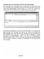
Configuring and Sending D-RATS QST Messages
Transferr ing Files with D-RATS
75
76
77
77
78
79
80
83
85
87
89
90
Pa ge iv
File Transfer Problems
Using and Creat ing D-RATS Forms
Stations and Sessions Tabs
Other D-RATS Capabilities
91
92
93
93
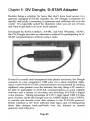
Chapter 9: DV Dongle, D·STAR Adapter
Computer System Requireme nts
Installing the DV Dongle Software on Your Computer
Selecting the DV Tool COM port and Audio Dev ices
Setting the Headset and Microph one Audio Levels
DV Dongle Operation
Connecting to Repeaters Linked to a Reflector
Dongle LED Status Indicators
Installation Problems
95
96
96
97
99
10 1
101
102
102
Appendix: D·STAR Web Pages
103
Page v
Page vi
About This Guide
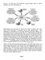
Using easy to understand language and illustrations, this guide
describes how the D-STAR system operates and provides guidance
for setting up your transceiver to be able to access D-STAR ' s many
features and modes of operation. We will go light on theory,
concentrat ing instead on the practical issues of getting things
programmed and maki ng voice and digita l data contacts.
D-STAR is an evolving technology. Thanks to improvements made
by leom and the effort of many hams creating and maintaining
programs such as Dplus, d*Chat, and D-RATS, D-STAR ' s
communication capabilities are far improved from several years ago.
The creation of the DV Dongle, which enables worldwide
communication without using a rad io, has added a whole new
dimension to D~ STA R operations.
In early 2009, when this book was written, the software running on
most gateways was Icom' s G2 program supplemented by Dplus
version 2.2. No doubt, future enhancements will continue to provide
more exciting new communication capabilities.
Lets get started!
Pa ge 1
Special Thanks To
We wish to thank all those that helped in the creation of this book.
Special thanks to Icom who materia lly supported the project with
technical help and generously allowed us to use the graphics from
various lea rn publications. Ray Novak , N9JA, learn's Amate ur
Radio Division Manage r was especially helpful in providing contacts
that were of assistance in co mpleting the project. Fred Var ian,
WDSERD, with lcom Tec hn ica l Support not only answered my many
questions , but also reviewed a draft co py of this book .
We are also indebted 10 Ceci l Casillas, WD6FZA, administrator and
champion of the Southern Ca lifornia PAPA repeater system who
supported the project by answe ring my questions and allowing me
access to their exce llent system of DSTAR repeaters. W ithout thei r
support I would have been unable to perform the testing and
experimentation necessary to ver ify many of the DSTAR features and
procedures presented in this book.
Severa l othe r PAPA syste m members were also supportive of my
effort s. Allen Klisky, KB60 YA answered questions and he lped me
run tests using digital mode operation with thedt'Chat and D-RATS
programs. Ted Petrina, W6SAT and Cra ig Davis, KM6AW both took
of the ir va luable time to review draft co pies of the book, providing
me with co rrections and suggestions.
Page 2
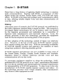
Chapter 1: D-STAR
Hams have a long history of applying digita l technology to amateur
radio communications. Starting with RTIY, a success ion of other
digital modes has ensued: Packet Radio, PSK, PACTOR and many
others. D-STAR is the latest and perhaps most comprehensive effort
to date, offering reliable digita l voice and data communication all
over the world.
History
After three years of research, the D·STAR protocol was published by
the JARL (Japanese Amateur Relay League) in 200 1. The research to
investigate digital technologies for use in amateur radio was funded
by the Japanese governme nt and undertaken by a committee of
Japanese radio manufacturers and interested observers . learn, the
primary promoter of this new technology, prov ided the equipment
used for the development and testing phase of the program.
At first, adoption of the technology outside of Japan was relatively
slow. However, in the last several years D-STAR repeater systems
have started coming into their own. With the increasing ava ilability
of D-STAR repeater systems and gateways, the numbers of hams
using these systems is showing dra matic growth.
D-STAR repeaters and gateways are now ava ilable in many area s of
the United States, Europe, Canada, South Amer ica and Australia.
Repeater s linked to Internet Gate ways provide voice and data
com munications all over the world .
To encoura ge equipment suppliers to adopt the tech nology, JARL
publ ished the D-STAR protocol as an "op en" specification that detai ls
the over-the-ai r interface and repeater/gateway transport requirements
for interoperability ofD-STAR equ ipment. To date, Icom is the only
manufacturer of D-STAR capable repeater systems and radios. As
the techno logy beco mes more widely adopted , other manufacturers
may chose to offer equi pment as wel l.
Page 3
0-5TAR Overview
D-STAR (Digital Smart Technologies for Amateur Radio) offers
digital voice and slow and high-speed data communications. The
slow-speed digital voice and data is transported at 4800 bps, with
3600 bps being used for voice and voice error correction, the
remaining 1200 bps is used for synchronization and general use. Of
this 1200 bps, about 900 bps is available for transporting data. Highspeed digital data communication is transported at 128 kbps, supports
Ethernet packets, and is fast enough for interactive Internet
applications.
By connecting repeater sites over the Internet forming, a world-wide
radio network, the D-STAR system provides state-of-the-art
functionality to amateur radio repeater systems.
D-STAR
Repealet
In D-STAR, voice communication is referred to as DV mode (digital
voice) operation. Voice is converted to a digital format using an
electronic chip called a CODEC, which encodes and decodes audio
signals in the AMBE (Advanced Multi-Band Excitation) format.
To the critical ear the audio quality of a D-STAR voice signal might
sound slightly inferior to a high quality FM signal, but is more than
adequate for intelligible voice communications.
Page 4
The nice thing about digital voice operation is that the quality of the
signal remains crystal clear until it is lost. As long as the signal
remains above a minimum threshold, it can be decoded without
degradation and will remain clear without the path noise or "picket
fencing" weak signal artifacts common on traditional FM mode
communications. If the signal falls below the level required for
decoding, communication will drop out or become garbled, sounding
a bit like the R202 Star Wars character.
At first, operating O-STAR is a bit unnerving. After years of using
conventional FM repeaters, its strange not to hear a squelch tail after
O-STAR repeaters drop the carrier almost
releasing PIT.
immediately upon releasing PIT on the transceiver; consequently the
momentary squelch tail hiss that we are accustomed to is not there.
Being conditioned to delay transmission until after you hear a
courtesy beep and then operating on a repeater without a beep can
throw you off. Even though O-STAR repeaters don't broadcast
courtesy beeps, it's still important to pause before replying, as it gives
other stations a chance to break in. Not to worry though, after using
D-STAR a bit that strange feeling soon goes away, being replace by
the thrill of using this new mode of communication.
Interestingly, in DV mode slow-speed 1200 bps digital data can be
transmitted at the same time, and on the same frequency while you
are engaged in a voice conversation. Since both voice and data are
being handled digitally, they can be transmitted together 0 11 the same
signal without any interference to your voice conversation.
Don't be misled by the tenn slow-speed, 1200 bps DV mode data is
more than capable of keeping up with typing on a keyboard and for
transmitting short messages and small amounts of data. Subtracting
out header and message blocking overhead, OV mode data has about
900 bps available for general use and is much faster than PSK31, but
slower than 9600 bps packet operation. Like packet, DV mode data is
unsuitable for sending large files or "s urfing the web."
In addition to the slow-speed DV data that can be transmitted
simultaneously with your voice on the 144, 440 MHz and 1.2 GHz
bands, D-STAR supports a high-speed digital data rate of 128k bps on
the 1.2 GHz band. Due to packet overhead and other factors, actual
Pag e 5
throughput is closer to 90k bps. Referred to as DO mode (digital
data), this high-speed data capability is unique in amateur radio
because it is fast enough to support exchanging large files, pictures
and for user-interactive Internet e-mail and web browser applications.
Connecting your PC, laptop or rDA is simply a matter of connecting
a cable to the radio, no external TNCs or other devices are requ ired.
For slow-speed data, depending upon the radio, either an RS-232
serial or USB cable is used. High-speed data connections are made
using a standard Ethernet cable. Low-speed data capabilities are built
into all VHF / UHF D-STAR transceivers currently being supplied by
leom. High- speed data is limited to rad ios with 1.2 GHz capabilities.
For emergency communications, one of the advantages of D-STAR' s
digital data capabilities is that messages can be locally transported
independent of the Internet when the " lines are down".
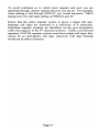
But wait, there is more! A single repeater or a grou p of repeaters can
be connected to the Internet via a device called a gateway and are
referred to as a "Zone." Gateways use the Internet to connect to other
D-STAR gateways and reflectors anywhere in the world. This allows
you to communicate to hams located in areas far removed from your
local repeater, somewhat similar to IRLP operation but with an
interesting added capability. Whenever you key-up, your call sign is
automatically transmitted via the digital transport mechanism built
into the radio. When the gateway routes your call, it also stores your
call sign locally and provides it to the Internet connected Trust
Page 6
Server. In this way the D-STAR system keeps track of which
repeater you were last heard on.
Tr'\Ist
Serv er
Reflector
Serve r
By entering the call sign of whom you want to contact into your
radio, you can make a directed call to that specific ham. The
technique is referred to as Call Sign Routing and unlike IRLP, you
don't need to know which repeater he is on. Periodically all gateways
synchronize their local data with data located on the Trust Server.
The gateway system uses that data to figure out which repeater your
friend was last heard on and automatically routes your call to that
repeater. Call Sign Routing can be thought of as being similar to how
a cell phone operates. As you travel around, the cell system "knows"
where you are at and directs incoming calls to the cell tower nearest
to your location. D-STAR works much the same way.
With Call Sign Routing, after entering the call sign of the person you
are trying to reach, the D-STAR system can automatically route your
call to other repeaters even if they are on a different band or in a
different city. As a result, no matter which repeater your friend might
have switched to, your call will be routed to where he was last heard.
This solves the prob lem of having to make calls on all the repeaters
that your friend might frequent.
Page 7
D-STAR's Bits and Bytes
O·STAR DV mode (slow-speed digital and voice) transceivers
produce an RF signal that is quite different tha n those produced by
conventional FM transceivers. The voice portion of the outp ut signal
is not FM modulated; audio is directly converted to a digital data
stream using a AMBE (Audio Multi Band Encoder) codec chip, in
tum the AMB E voice data is co mbined with other dig ital data to fonn
a simultaneous composite voice and digital data stream, which is then
tran smitted as a OMSK modulated signal.
Within the D-STAR specification, the exact format of this composite
digital stream is defined as the Common Air Interface, or CAl
protocol and is made up of a Radio Header followed by the data
payload. The Radio Header consists of a series of synchronizing and
control bits followed by four call signs used to route the signal to its
intended destination. The data payload portion consists of alternating
Frames of Voice and Data information: a frame of 72 bits of voice
followed by a frame of 24 bits of data, a pattern which cont inuously
repeats until followed by a unique termination frame of 48 bits. This
pattern of alternating digital voice and data frames occurs regardless
if there is voice and no data, or if there is data and no voice. Space in
the payload is always reserved for the voice and data frames
regard less of whether they are used or not.
For those interested in the detailed structure of the Common Air
Interface protocol and other technical details of the D-STAR overthe-air protocol, an English copy of the JARL specification can be
downloaded from
www.jarl .com/d- starlshogen.pdf
A more comprehensive look at the D-STAR over-the-air protocol is
provided by Peter Loveall, AE5PL in his excellent paper titled DS TAR Uncovered. This paper provides additional insight and
information beyond what is in the JARL specification, including a
summary of Icorn' s enhancements to the base specification.
http://www.aprs-is.netldownloads/DStar/DSTARUncovered.pdf
PageS
Both of the above documents are quite technical, describing the airlink communication protocol in exacting detail and are the basis for
how the system is designed. These documents are primarily of
interest to those designing D-STAR compatible equipment or
software.
If this bits and bytes stuff is all Greek to you, don't worry, a detailed
understanding of the underly ing voice and data transmission protocol
is not essential for enjoyi ng the benefits of D-STAR operation. . Jt's
really no different than driving modern automobiles, using computers
or accessing the Internet, all of which rely on complex systems and do
not necessitate our detailed understanding before being able to
successfully operate them.
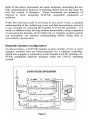
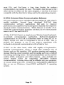
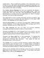
Repeate r System Configuration
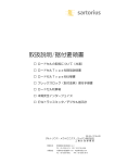
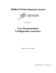
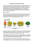
As shown below, a D-STAR repeater system consists of one or more
repeater modules that are interconnected via a repeater controller,
which also supports a connection to the Internet via a PC running a DSTAR compatible gateway program under the LINUX operating
system.
0-5TAR SYSTEMCONFIGURATION
I
n 0. • • •
-
~
ij
O· .. aa
•
0·0· _
ID-R P2C (Repeale r OOIllroiler)
l...!:::::
.r
ID-RP2V {1028 Hz Digital voice repeatef)
~ij
l"_ , ;
ij
'f'
0• ••
~ij}
-
~~~'
ID·RP2D (( 28 Hz Data repeater)
O· • • •
_H-
-
IQ.f!P4000 V (UHF (440MHz) digftalllOice repeater)
~-a ij
PC Based
O' _ i:lii
-
ID-RP2000V (VHF (144MHz)
- ijfdig~a l
Page 9
voice repoot ....)
Internet )
A repeater system can be configured with repeat er modules
supporting d ig ita l voice on the 144 MHz, 440 MHz and 1.2 G Hz
bands. A given insta llation may include any co mbination of the three
vo ice modul es. Notice that if high. speed d igital data is to be
supported, a sepa rate 1.2 GHz d igita l data repeater modul e is
requ ired.
A repeate r system can be co nfigu red w ithout includ ing a PC gatewa y
server to the Internet. Of course, the repeater system loses the
ca pability of communicating w ith remote gateways and repeaters, but
still provides functiona lity similar to that provided by conventional
stand-alone FM mode repeaters .
It' s common practice to refer to ind ividua l repeater mod ules
connected to a repea ter controller in a D-STAR system as nodes,
modules or ports. For exa mple, the four repeate r modu les shown in
the preceding diagram can alternately be referred to as nodes,
modules or ports. Regardless of which term is used, they all refer to a
spec ific repeater module . The term port is derived from the practice
of referring to ind ivid ua l repeater modul es as being con nected to a
repeater controller' s ports.
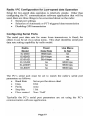
The agreed upon practice for naming these modules is to add a letter
desig nati ng the ind iv idual port after the main call sign for the system.
Regard less of the length of the ma in ca ll sign, the port designat ion is
always placed in the 8tb chara cter position, preceded by as many
spaces as necessary to fall in the 8tb po sition.
The "_" under line cha racters below are on ly used to illustrate the
requ ired spaces. When entering an actual call, use " real" spaces not
the underline.
W6XYZ_A
W6XYZ_A
W6XYZ_B
W6XVZ_ C
W6XYZ_G
DV
DD
DV
DV
1.2 G Hz vo ice repeater, Port A
1.2 G Hz high- speed data repeater, Port A
440 MHz band data I vo ice repeater, Port B
144 Mllz band data I voice repeater, Port C
The system's Internet gateway , Port G
Page 10
To avoid confusion as to which local repeater and port you are
operating through, always indicate the port you are on. For example,
when making a call through W6XYZ, you would announce "N6 FN
(using your own call sign) calling on W6XYZ port 8."
Notice that the entire repeater system is given a single call sign.
Repeater call signs are restricted to a maximum of 6 characters.
Individual repeater modules are identified via the port designation
suffix that appears in the 8th character position. Unlike conventional
repeaters, D·STAR repeater systems must have unique call signs, they
cannot be an individual' s call sign, otherwise Call Sign Routing
would not be able to function.
Page 11
Programm ing 0-5TAR Call Sign Parameters
Programming a tran sce iver to make calls (or for linking to a gateway
or reflecto r) involves programming call signs into the four parameters
of the Call Sign Routing Register:
• UR CALL
Call of the station, node or reflector you are calling.
• RPT1
Call of the local repeater node you are calling from.
• RPT2
Call of a destination repeater or yo ur local gateway.
• MY CALL Your own call sign, or call sign variati ons.
Different transceiver models may display slightly diffe rent
abbreviations for these four parameters, but on all radios they
acco mplish the same thing. These parameters are programmed in
different ways depe nding upon how you are making the call : simplex,
local repeater, Repeater Node or Ca ll Sign Routing, and Gateway or
Reflector linking.
UR CALL Th is is e ither the station you want to talk to, or is set to
CQCQCQ so you can ca ll CQ or work round-table as on a
co nventional FM repeater . When using a gateway, UR CALL is used
to designate the call sign of the individua l you are calling, or it can
also be used to control gateway linking or for accessing a reflector.
RPT1 Used to enter the call sign of the loca l repeat er you are using.
The 81h character position is special as it spec ifies the band and port
you are operating on. You need to insert spaces as necessary to make
sure that the port switch letter (A , B or C) falls in the 81h character
position.
RPT2 This is the ca ll sign of where we want our tran smission to go,
eithe r to one of the other ports on the same repeate r system, or to the
gateway used to access the D-STAR network . Again, the 8th
character position is special because it is used for the port switch
designation letter: A, B, C or G.
MY CALL Th is is used for your own ca ll sign, or perhaps a variation
of it with a suffix indicat ing different radios that you might be using.
Page 12
In this book, the Call Sign Routing Register refers to the ca ll sign
memory that the radio uses to make D-STAR calls . As we will see in
Cha pter 4, depending upon the radio, there are several ways for
making entries into the Call Sign Routing Register.
• Manually editing the current Call Sign Routing Register
• Copy ing from the UrCall, Repeater and MyCall memory ban ks
• Using the [RX.CS] key one-to uch reply feature
• Recalling a memory channel that has these parameters set
Generally you would not want to be programming call signs
whenever yo u wish to ca ll someone. And, you certa inly don't want to
attemp t programming call signs while driving. The normal practice is
to store in advance a ll call and repeater node combinations you expect
to use into call sign memories within the transceiver. Once your
transceiver has been programmed, it' s a simple matter of reca lling the
correc t ca ll sequence from memory .
Loca l DSTAR repeat er grou ps typically prov ide the informatio n
required for accessing yo ur local repeater s. In addition, as we shall
see in Chapter 6, there are several web-based resources provid ing call
sign information for D-STA R systems all over the world.
Using D-STAR Gateways
,
One of the key features of D· STAR is the ability to commun icate
with other D-STAR systems over the Internet. Indeed, connecting
repeater systems via gateways is one of the most powerful aspects of
D-STAR operation. Most of the enhanced capabi lities of D-STA R
repeater systems rely on their gateway connection.
Since so much can be done via the gateway system, the creators of DSTAR have implemented a worldwide gateway user registration
system in order to prevent misuse of the resource. Users must register
to be able to operate any D-STAR features that involve gateway
access to the Internet. Without registration you are genera lly limited
to simplex and local repeater operation.
Except for the "O perating Simplex" and "Local I Same Repeater
Operation" section s be low, you will need to registe r for gateway
access if yo u wish to try any of the features described in the followi ng
sections
Page 13
Operating Simplex
D-STAR transceivers are capable of working station-to-station on
simplex, ju st like conventional FM transceivers. One advantage of a
D-STAR radio is that it' s already equipped for digital
communications. This can simplify situations when you want to
transmit data, perhaps for emergency communications or public
service events such as aid stations spread along a bike or foot race. If
high-speed communications are required, two 1.2 GHz, 10· J
transceivers can transfer data directly without the use of a repeater.
Simplex Operation
ure.ll: CQCOCQ
UrC.II:
RPT1: notUMd
RPT2: no tUMd
cccccc
RPT1: no! uud
RPT2: not .....d
MyC. II: N6FN
MyC.ll : WD6l'ZA
To talk to anyone on simplex without having to input their call sign,
the UrCal! field is programmed with CQCQCQ. Since repeaters are
not used when working simplex, depend ing upon the radio, RPT1 and
RPT2 are programmed as "not used" or left blank. And of course,
your own call sign is used in the MyCall field.
Here we see that N6FN and WD6FZA, except for their individual call
signs, have their radios set the same way and will be able to talk to
anyone on their simplex frequency.
Pa ge 14
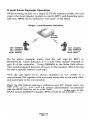
Local I Same Repeater Operation
When working locally on a single D-STAR repeater module, the call
sign of the local repeater module is used in RPT1 , and depending upon
the radio, RPT2 can be marked as " not used" or left blank.
Single I Local Repeat er Operation
•
~
urcen
~U
urCaU: CQCQCQ
e
RPT1: KI6MG N
RPT2: nol u sed
MyCaU: WD6FZA
CQCQCQ
RPT1: KI6MG N B
RPT2: not us&d
MyCa ll: N6FN
In the above exam ple notice that the call sign for RPT1 is
KI6MGN_B, which indicates it is a 440 MHz repeater attached to
port B of the controlle r. Using CQCQCQ in the UrCal! field allows
inter-communication between all users on the repeater without having
to enter a specific station' s ca ll sign.
"
With the call signs set as shown, operati on is vel)' similar to a
conve ntional FM repeate r with everyone being able to hear each other
and participate in the conversation.
Note: So that linked gateway s, reflectors and DV Dongle users can
hear your traffic, most D-STAR system administrators recommend
that the RPT2 field be set to your local gateway. In the case of the
PAPA system KI6MGN repeater , RPT2 would be set to KI6MGN_G.
Page 15
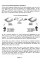
Loca l Cross-band Repeate r Operation
If your local repeater system has two or more modules, you can work
cross-band ju st as if you were operating on a single repeater. In this
case, RPT1 specifies which repeater you are operating through, and
RPT2 specifies the destination repeater. The local repeater controller
takes care of routing the signals between the two ports.
Local Cross-Band Operation
Port Y'A
~Port C
I•
440 MHz
Repeater
Control ler
146 MHz
R. peater
Repeater
Kl6MGNB
Kl6MGN C
uecan: cccccc
Ur<:. ll : cccccc
RPT1: KI6MGN B
RPT2: KI6MGN C
MyCaII: WD6FZA
RPT1: Kl6MGN C
RPT2: Kl6MGN B
MyC.II: N6FN
In this example WD6FZA is going through the KI6MGN_B, 440
MHz repeater, and N6FN is going through the KI6MGN_C 146 MHz
repeater. It is important that the port switch designation (the letters B
and C in this case) is programmed into the glb character position.
Notice that since the two stations involved are on separate repeater
modules serviced by the same repeater controller that a gateway is not
being used and that the call signs they programmed into RPT1 and
RPT2 of their radios are reversed.
When the station hearing the call, in this case N6FN, wants to
respond he needs to set his radio' s RPT2 field to the radio module
being used by the calling station, in this case KI6MGN_B. But keep
in mind that the calling station needs to identify which module he is
on so the answering station can configure his radio to the repeater
module that the calling station is using.
Pa ge 16
Repeater Node Rout ing
Repeater Node Routing, also called "Source Routing," "Port Linking"
or a "Zone Call" allows the user to specify a specific repeater node as
the destination for his transmission. This can be used to place a call
to a specific ham or perhaps as a way of announcing your presence or
calling CQ on a distant repeater.
Using this method a user can either send his signal to a different port
on the same repeater system or to any gateway connected repeater
node in the world.
Repeater Node Routing
UrCall: IKI6MGNB
RPT1: W301 C
RPT2: W30 1 G
MyCaU: W3XXX
u re all : 1W30 1 C
RPT1: KI6MGN B
RPT2: KI6MGN G
MyCal1: N6FN
I
To use Repeater Node Routing a " I " is placed in front of the
destination repeater' s call sign in the Ureal! field. The leading « I "
character lets the controller know you are making a call to a specific
repeater node and that it's not the call sign of a person.
Note: After N6FN made his call to the W301_ C repeater, W3XXX
configured his radio using Node Routing to route his eall back to
NGFN 's repeater, KI6MGN_B. The "G" suffix in the g l h character
position of the RPT2 field indicates that the signal is to be routed to
the gateway.
When someone answers a call made using Node Routing, they must
configure their radio to route their signal back to the repeater module
that the source radio is using. Therefore, as is generally the case
when using D-STAR, the calling station needs to identify which
repeater and port he is calling from.
Page 17
A recervmg station, in addition to hearing the transmrtttng station
identify the repeater he is calling from, can also examine the Received
Call memory on his radio. Refer to the Received Call History
procedure in Chapter 4 for details on how to examine the Received
Call memory.
When you are finished with yo ur QSO on the remote repeater you
need to change the UrCall field back to CQCQCQ, otherwise when
making any further contacts, even on yo ur local repeater, your voice
will still be routed to and heard on the remote repeater indicated in the
urcen field. This is an easy mistake to make and I suppose everyone
has done it at one time or another.
I supposedly know better. but here is how easy it is to make a
mistake. Hearing Toshi JFI CXH, a Japanese station, calling, on our
local D-STAR repeater, I configured my radio for Node Routing back
to his repeater by placing his local repeater call sign, IJP IYIQA into
my radio's UrCal! field. So far so good and the QSO went fine.
The problem "s nuck in" after my QSO with Toshi in Japan ended.
Just as I signed off with Toshi, I was immediately called by another
station on my local repeater. Not thinking, I returned his call and we
chatted a bit about making contacts to Japan and a few other topics.
Only after finishing the follow-on QSO did I remember that I had
neglected to switch my UrCall field back to CQCQCQ . The result was
that my side of the follow-on conversation was broadcast in Japan! I
was the cause of several minutes of unintended interference on their
repeater. Not good!
This can happen when using any of the D-STAR modes where you
are either routed to or connected to a remote repeater or reflector. Its
important to remember to reconfigure your radio's UrCal! field and if
necessary also the RPT1 and RPT2 fields back to where they need to
be to prevent " interference" on a remote repeater node. Stay alert and
don't let this happen to you.
Page 18
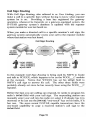
Call Sig n Routi ng
With Call Sign Routing, also referred to as User Linking, you can
make a call to a specific ham without having to know what repeater
system he is on. Providing a ham has registered for gateway
operation, whenever he transmits on a gateway-equipped system, the
D-STAR gateway system's database is updated with the repeater
system module he was last heard on.
When you make a directed call to a specific amateur's call sign, the
gateway system automatically routes your call to the repeater module
whe re that station was last heard.
Call Sign Routing
urcen:
Ureall : N6FN
RPT1: W301 C
W3XXX
RPT1: KI6MGN B
RPT2: Kl6MGN G
My-Call: N6f N
" RPT2: W301 G
My-Call: W3XXX
In this example Call Sign Routing is being used by N6FN to locate
and talk to W3XXX, which happens to be on
. the W30I- C module
at the moment. Notice that W3XXX has set his UrCal! field to
N6FN's call sign to answer his calL The other three fields were
probably already set since he has recently been using the W301_C
repeater.
Before the ham you are calling can respond, he needs to program his
radio' s UrCal! field with your call sign. The responding station can
manually enter your call into his radio (or select it if already has it in
memory) or he can use the [RX-CS] "one-touch" key on his radio, if it
has one. The more recent D-STAR capable transceivers have the
one-touch capability to copy a received station's call sign to the
UrCafl field.
Pa ge 19
Using the one-touch reply [RX·CS] key only temporarily copies
N6FN's call sign into the UrCal! field, and will last until something
else is placed into the UrCal! field. It' s not permanently saved
anywhere. One-touch operation is described in the following section.
Note that both stations have set RPT2 to their local gateway. Doing so
has allowed the gateway system to rout N6FN's call to the last
repeater module that W3XXX has been heard on. As a side note, it
also allows Dongle users to hear both sides of the conversation.
One of the issues with Call Sign Routing is that the "last heard on"
process can take an hour or more to update the database; therefore the
user may no longer be on that repeater.
One way to partially get around the problem, so that you can
immediately receive calls when away from your local repeater, is as
soon as yo u are on another D-STAR repeater system place a call back
to your local repeater. Then at least your local repeater system will
immediately know what repeater you are on, and if anyone calls you
from there using Call Sign Routing, their call will be forwarded to
where you are at.
Of course, if your friend is using CQCQCQ in the UrCal! field when
operating on your local home repeater, you will not receive any calls
directed to you unless he knows you are out of town and switches
over to Call Sign Routing by entering your call sign into his UrCal!
field.
By the way, if out of town, what method do you usc to call back to
your home repeater system? You have a couple of choices: you could
either use Call Sign Routing if yo u wanted to call a particular station,
or if you j ust wanted to check in with a general call on your home
repeater you could use Repeater Node Routing .
When you are done talking with your friend you need to change your
UrCatl field back to CaCQCQ, otherwise when making any further
contacts, even on your local repeater, your voice will still be routed to
and heard on the remote repeater where your friend was last
operating.
Pa ge 20
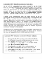
Setting the UrCall fi eld back to CQCQCQ
As we have seen, its impo rtant to cha nge you r rad io' s UrCal! ca ll sign
ro uting field back to CQCQCQ after setting it to something e lse for
making calls to specific stations, repeaters or send ing linking
com mands as we will see in the next chapter.
Setting Ureal! fi eld to CQCQCQ on the IC-91AD and IC-92A D:
1. Starting with the DV operating mode selected and a DSTAR repeater freq uency being displayed on the scree n.
2. Press [O/Ca] until you hear a beep, the n release.
Setting Ureal! field to CQCQCQ on the IC-2820:
1. Starting wit h the DV operati ng mode select ed.
2. If necessary, press [F] twice to access the DV mode
function key s. (CS CO CQ R>CS etc .)
3. Press [Cal to set the UR field to CQCQCQ.
To set CQCQCQ on other rad ios, refer to the Icom user manua l for
yo ur rad io.
.
Page 21
One-touch Reply
The one-touch feature, available on newer model learn transceivers
that have the [RX.cS] key, is a handy way of responding to a call. As
calls are received they are automatically stored in the Call History
memory and are available for use by the one-touch feature. Pressing
the [RX..cS] key sets the radio to respond to the most recent called
received.
However, if another cal1ed is received after the one you want to
respond to, you will need to select the desired eall from the Received
Call History memory as shown in step 3 below.
Be aware, that if the repeater produces a transmission after the desired
call was received, one-touch may copy the repeater' s gateway call
sign to the UrCal! field. If so, skip step 2 and use step 3 to select the
desired call.
Using One-touch on the IC-91AD and IC92AD :
I. First make sure that your own call sign has been set into the
MY call field and that RPT1 and RPT2 are set for Call Sign
Routing from your local repeater.
2. (Only use Step 2 or 3) After a call has been received, press
and hold the [CALU RX-eS] key one second to set the Call
Sign Routing Register to respond to the most recently
received call.
3. Or if you want to select a call sign from a list of recently
received call signs, press and hold the [CALU RX.cS] key
and rotate [DIAL] to select the desired call sign record.
Recently received call signs stored in the Call History
Memory are displayed at the bottom of the screen.
4. Everything is now set; press [PTT] to transmit.
Pag e 22
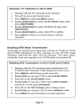
Using One-touch on the le-2820:
I. First make sure that your own call sign has been set into the
MY call field and that RPT1 and RPT2 are set for Call Sign
Routing from your local repeater.
2. After a call has been received, press [F] twice to access the
DV mode function keys. (CS CDCQ R>CS etc.)
3. (Only use Step 3 or 4) Press [R>CS] key to set the Call
Sign Routing Register to respond to the most recently
received call.
4. Or if yo u want to select a call sign from a list of recently
received call signs, press the [CD] key and rotate
[MAIN- BAND] to select the desired CALLE R call sign from
the RXCALL SIGN history memory.
5. Everything is now set; press [PIT] to transmit.
Important: After using the one-touch feature to make a reply, be sure
to change your radio' s UrCall field back to C~C QC Q .
Automatic Call Sign Update Prevention
Icom' s D-STAR radios have two menus that can enable received call
signs to automatically replace call signs in the Call Sign Routing
Register. In general you don't want this to happen, so you should
verify that they are turned OFF, which is the default setting for these
two menus.
The "RX Call Sign Auto Write" menu should be set to OFF to
prevent having received station's call sign automatically replace your
UrCall setting. The default setting is OFF.
The "Repeater Call Sign Auto Write" menu should be set to OFF to
prevent having received station's RPTI and RPTI call signs
automatically replace your RPTI and RPTI settings. The default
setting is OFF.
Pa ge 23
Multicast Gro ups
Multicast is a feature that leom added with the G2 version of the
gateway softwa re. Mult icast allows an administrator to associate a
group ofrepeater nodes with an alias (a name of his choo sing). Us ing
a Multicast group name allows an administrator to route transm issions
between as many as I I repeate r nodes. Multicast group names of up
to seven characters long always start with the character " I " . When
this name is referred to, it has the same effect as refere ncing all of the
repeat er node s in the network at once.
URCALL :
RPT1:
RPT2:
MY CALL:
/CA 1200
Multicast group name.
WR6BR N_C Local modu le you are linking from.
WR6BR N_G Gate way for local repeater module.
Your own ca ll sign.
N6XXX
While users don't have the capability of creating Multicast Group s,
they can make use of the feature by placing the group name in their
UrCall fie ld. When a user transmits using a Multicast group name, he
will be heard on all the repeater node s in the group . The user' s loca l
gateway accomplishes this by sending a stream of data to each of the
"
nodes in the group.
So that users on remote repeaters can respond , it is important to
announce the repeater you are calling from and the network name
being used. If responding stations don't use the network name in
their UrCal! field, they will not be heard on all the repeaters in the
network .
Im porta nt : At the end of the round table or net and going back to
normal operation, it is important that each station terminate multicast
operatio n by resetting thei r UrCal! field back to COCQCQ or something
e lse. Otherwise, their transmissions will still go out to the entire
group of repeaters.
Page 24
Identify Where You Are Calling From and Wait
Whenever making calls on a DMSTAR system it is imperative that you
identify the repeater and port you are calling from. Otherwise when
a station hears yo ur call he won't know if you are local or elsewhere.
If you are not on his local repeater he may need to know where you
are transmitting from in case he needs to change the settings in his
UrCall and RPT2 call sign fields.
Typically you would state the location of the repeater and which port
you are on. For instance if operating on the PAPA system Mount
Palomar repeater you might say that you are "using Mount Palomar
port 8. "
This brings up the second point to remember when making calls over
the D·STAR system. After making a call, monitor long enough for a
responding station to make any radio changes necessary. Since it is
likely that the responding station was otherwise preoccupied, it may
take a few minutes for him to "put down" what he was doing, change
his radio settings and return your call. Repeating your call once or
twice (don't get carried away here like calling CQ on HF) may allow
the station to make note of where you are at so he can make the
required settings.
On repeaters with frequent traffic, you may-- also want to hold
transmission a sufficient amount of time to allow a receiving station
to use his "one-touch reply" key to copy your call sign information to
his radio' s D·STAR call sign fields. Remember, hc has to hear your
call, pick up his radio and then press the key. ' If your call is too short,
by the time he is ready to press the key your signal may have been
pushed down in the stack of calls in the Call History Memory.
Remember, one-touch retrieves the most recent call from the Call
History Memory.
Pag e 25
Limiting Position Beacon ing and Data Mode Operation
Whenever multiple D-STAR repeater nodes are linked together for
group, emergency or net operations, via Multicast or the Dplus
linking methods described in the next chapter, automatic APRS /
DPRS GP$ position beaconing should be turned ofT or be set to
transmit only on PIT. Automatic beaconing every few minutes will
result in data being transmitted to all connected nodes, causing
collisions (doubling) with other user' s transmissions.
Likewise, for the same reason, cons ider delaying DV data mode
transmission until the net is over or switch to another repeater system.
While data can be sent along with a voice transmission, if automatic
data transmission has been selected, it won't wait for a voice
transmission to occur. It will occur anytime data is ready to be sent.
Page 26
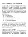
Chapter 5: DV Short Text Messaging
You can configure yo ur transceiver to send sho rt message s when ever
you tran smit. The se message s are tran smitted along with you r vo ice
every time yo u transm it, and will show up the RX Message buffer in
other user ' s rad ios. Ty pica lly up to five messages, each a max imum
of 20 characters in length, ca n be programmed into the rad io. Before
tra nsmitti ng you select which of the five you w ish to transmit.
The messages arc free form and ca n be used to convey a var iety of
information. It' s too bad they are on ly 20 characte rs long, as it ca n be
a cha llenge to figure out how to fit what yo u want to say using on ly
20 characters.
Some common uses;
•
•
•
•
•
•
•
Radio configuration
Your name and locat ion
You r fu ll name (first and last)
Spec ial announcem ents
Rad io sett ings to use for answering your call
Reflector yo u are using
You r web page or ema il address
Pro viding instructions on how users should set their radio to make a
return ca ll back to you is an interestin g use for short status mess agi ng.
I found several Japanese stations using th is technique. Their short
stat us messages we re formatted similar to this: " Set Ur to IJPIXXX,"
and I' ve see n others with the message " Use One Touch Butt on."
Even if yo u don' t use th is technique yo urself, it' s worth rem ember ing
if you hear a call and are unsure of how to call back. They mig ht be
telli ng you via short messaging.
Prog ramm ing OV Short Messages
Program ming messages into the rad io is relatively stra ightforward.
I like using lower-case characters to help make run together words or
abbrev iations understandable without having to insert a space . For
instance, here is what I have programmed in one of my memories:
" Bernie SanDiego NoCo". Thi s comes to exactly 20 characters and
Page 57
would not have fit had I used spaces. NoCo stands for North County
and may not be obvious, but SanDiego is quite understandable.
Unfortunately there is a drawback to using lower-case characters.
Earlier radios such as the 1D-800H, IC· Y82 and perhaps others can
only display upper-case characters, so a message received on those
radios may not display as intended.
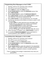
Programming and Transmitting
IC-91AD and IC-92AD:
Short Messages on the
I. Starting with the DY operating mode selected and a 0 STAR repeater frequency being displayed on the screen.
2. Press [ MENU], which brings up the menu list.
3. Rotate [D IAL] or use [. ] / [T] to select MESSAGE I POS .
4. Press [ .. ] to access the MESSAGE J POSITION screen.
5. Rotate [ DIAL] or use [. ] / [T ] to select TX MESSAGE.
6. Press [ .. ] to go to the TX MESSAGE editing screen.
7. Rotate [ DIAL] or use [.] / [T] to select one ofthe five
memory channels Ch01-C h05 or O FF. (Note: OFF is used to
~
disable message transmissions.)
8. Press [ .. ] to start programming your message.
9. Use the keys as described at bottom of the screen to enter
your message text.
10. When editing is complete, press [5/ .-J] to save the message
and return to the TX MESSAGE screen.
I I. Before returning to normal operation, rotate [DIAL] or use
[. ] / [T ] to select the message channel Ch01-C h05 you
wish to transmit, or select OFF if you wish to disable
message transmission.
12. Press [ MENU] to exit and return to normal operation.
Note: If enabled, the message is transmitted every time
you press [PIT].
Pag e 58
Programming Short Messages on the IC-2820:
I. Starting with the DV operating mode selected.
2. Press [F] to access the function keys
3. Press [MENU] to select the MENU screen .
4. Rotate [MAIN- SAND] to select DV MESSAGE screen, then
press [MAIN-SAND].
5. Rotate [MAIN-SAND] to se lect TX MESSAGE MEMORY.
6. Press [MAIN-SAND] and then rotate [MAIN- SAND] to select
one of the five TX memory cha nnels 01-<l5.
7. Press [MAIN- SAND] to start programm ing your message.
8. Use the key functions at the botto m of screen to enter or ed it
yo ur message.
a) Press [ABC] to select betwee n lower and uppe r case
b) Press [1/ ] to select between numbe rs and sy mbo ls
c) Rotate [MAIN- BAND] to select cha racters
d) Use [<] and [>] keys to move entry position cursor
e) Press [CLR] to clear selected characters
f) Press [CLR]I sec to clear all characters afte r the cursor
9. When message is comp lete, press [MAIN-BAND] to save it.
10. To ex it the TX MESSAGE MEMORY screen and return to
normal operat ion, press [BACK] as required .
Transmitting Short Messages on the IC-2820:
I. Starting with the DV operating mode selec ted.
2. Press [F] to access the funct ion keys
3. Press [MSG] to select the MESSAGE screen.
4. Rotate [MA IN-SAND) to select TX MESSAGE screen, then
press [MAIN-BAND].
5. Rotate [MAIN-SAND} to select the channe l to be transmitted
Ch01 - CH05, or select OFF to d isable message transm ission .
6. Press [BACK] as required to retu rn to norma l operatio n.
Note: If enabled, the message is transmitted every time you
press [PIT] .
Page 59
Reviewing Short Messages
Only the last messag e received can be viewed . Th is can present a
probl em , because it ca n be overwritten if anothe r message ha ppe ns to
arrive before you ha ve a chance to view the me ssage.
Reviewing Received Short Messages on the IC-91AD and
IC-92AD:
1. Start ing with the DV operating mode selected and a D·
STA R rep eater frequ en cy bein g d isplayed on the screen.
2.
Press [MENU], which brings up the menu list.
3.
4.
5.
6.
7.
Rotate [DIAL] o r use [ .... ] / [T ] to select MESSAGEJ POS.
Press [ ...] to access the MESSAGE J POSITION screen.
Rotate [DIAL] or use [ .... ] / [" ] to se lect the RXMESSAGE.
Press [ ...] to v iew the RX MESSAGE screen.
Rotate [DIAL] or use [ .... ] / [T ] to toggle between viewing
the recei ved MESSAGE or the CALLER ' s ca ll sign.
8. Press [5/ .-1] to return to the RX MESSAGE screen.
9.
Press [MENU] to exit and return to norm al ope ration.
Reviewing Received Status Messages on the IC-2820:
I . Sta rting w ith the DV operati ng mod e selected.
2. Press [F] to acce ss the function key s
3. Press [MENU] to select the MENU screen.
4. Rotate [MAIN- SAND] to select DV MESSAGE screen, then
press [MAIN- BAND].
5. Rotate [MAIN-BAND] to select RX MESSAGE.
6. Press [MAIN-SAND] to vie w the RX MESSAGE scre en .
7. Press [BACK] 3 ti mes to ex it and return to normal operation.
Page 60
Chapter 6: Internet Resou rces
Amateu r radio is fortunate to have enterp rising program mers whom
have authored a number of innovative and usefu l D-STAR web pag e
programs. Lets examine a cou ple of the most pop ular one s: D-STAR
Calculator andj Findu.
D-STAR Routing and Linking Calculator
To as sist amate urs w ith programmi ng the ca ll routing parameters for
their rad ios, Ed Woodrich, WA4YIH has developed an easy to use
program, D-STAR Calculator. The program operates on-line via t he
Internet and uses pull -down me nus to ma ke repeater and routing
se lection s.
Yo u start out by selecting t he local repeater and module that yo u are
usin g to get to the gateway. Next you select the D-STA R call routing
mode that will be used to ro ute the ca ll. Fina lly the rem ote repeater
mod ule yo u want your signal to co me out of is selected. After all th is
informat ion has been selected, the calculator displays the sett ings yo u
need to program into your radio for maki ng the call .
This program rea lly simplifies findi ng repeaters and programm ing the
Call Sign Routing Register; anybody ca n do it!
Operating the 0-5TAR Calculator Program
T his program contai ns a full list of repeaters and reflectors that are
availabl e for use worldwid e. US repeat ers are listed by state and ci ty.
If you wan t to make a call to a foreign country , a pull-down list
makes it ea sy to determi ne which repeaters are ava ilab le by country,
province and city.
Page 61
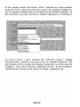
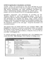
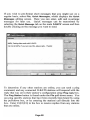
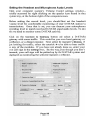
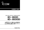
In the sample screen shot below, after J selected my local repeater
using the Source Repeater pull-down menu, the program displayed a
list of repeater modules that are available on the selected repeater. In
this case there was only one Source Module displayed, so I selected it.
R So
''l UMed Slates , California San Diego K16KQUGateway
"".~
.
, ,,
.
Source
Module
Function Source Route
Destination l ocal Repeater
v
"
v
t eeer Repeater ",rth Gateway
Repeater Echo Test
ReDQaler Slatus
.y
lkstinatioli
v
....
},{odule Specific User
li nk 10Repeater
Link 10 Rdector
. . . Unlink Repeater
J::!!g!!:§f'!.ed Data
As shown above, I then selected the D-STAR routing I linking
Function that I wanted to use from a list of available functions. The
list includes all the routing and linking modes that were discussed in
Chapters I and 2 plus one more, High-Speed Data. In this example I
selected Source Route as the mode of routing I wanted to usc.
Page 62
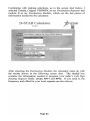
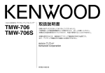
Continuing with making selections, as in the screen shot below, I
selected Canada, Calgary VE6WRN, as my Destination Repeater and
module B as my Destination Module, which are the last pieces of
information needed by the calculator.
D-STAR Calculator
-STAR
i
1.1.2.0
~~ Un~ed States, CaliforniaSan Diego Kl6KQU Gateway
After selecting the Destination Module, the calculator came up with
the results shown in the following screen shot. The shaded box
contains the information needed to program your radio' s Call Sign
Routing Register fields: UrCal!, RPT1 and RPT2. I f you need it, the
frequency and offset for your local repeater are also shown.
Page 63
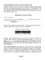
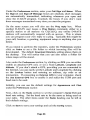
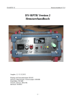
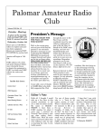
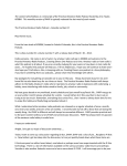
Below the shaded box, the program displays a call routing diagram.
At the sides and bottom are sample scripts suggesting how to identify
when maki ng the ca ll. Besides giving the ir locat ion and the repeater
module they are using, the scripts show the two hams exchang ing
repeater freque ncy and offset informatio n. Typically when operating
on D-STAR, exc hanging repeater frequenc ies is unnecessary.
Programming for- talkiri g on Kl6KQU (port DV B) w
VE6\VR." (port D\' B)
YOtiR;; I VE 15WRNB
RPTl: KI 6KQU- B
RPT1c KI 6 KQU-G
. ~. T . 441.8.\00 ) IHr
Set "'"
0 0; 5.ססOO ) IHz
ors«.
"., ,
"' f~t~S ll ~
rID lIta<
SanDitgo
CA li SA.
talking
rm
K16KQ';;
(portOV
B) and my
raGo n see
H7S400~
~~
r m nur
CllJiary .
rm ~
~:?
=~
~- ~
~
"
fl
U::Jl
00
\ 'E6WRN
(port OV
B) and my
rlldio is
~
.,. ~...,"O
,
': '.
. +s.OOOO
.s, .
CQ CQ CQ This is (1'OUr t aD. sign)
~stffiing 011 1M SM Dit go repeater ,
Say Howdy!
Kl6KQU (portDV B)
As yo u can see, the program is simple to use and by making a few list
driven selections you are prov ided with all the parameters necessary
for progra mming your radio to make the ca ll.
D-STAR Calculator can be fou nd at the followi ng URL:
http://www.dstarinfo.com/Calculator/
Page 64
jFindu Repeater Locator and Last Heard Lists
Another useful function is to be able to find out when, and on what
repeater a station was last heard. By clicking on the Last Heard Lists
link found at: http://www.jfindu.nethome page you can find out.In
the example below, I have input WD6FZA and clicked the " Incl ude
D·STAR last heard?" box.
j Findu L oca t or Site
Home > L!I5t Heard Lists
Enter callsign (11<:> SSlD) or object neme: ~~~.0
(If
enter a 3-S character prm.~: [
I
List Poaiticna
-~
-_~ .-~- - ~~.=:J
:lnchide D-STAR last Mard? 0
I
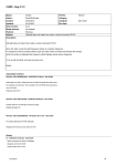
The result is displayed as show n below. Ifth e person has been using
APRS, a status line for that mode is also displayed.
WD6f V . Last Heard 0 11 DS T.\R
111111IWD6f L4. 3h4:m-l3s K1~~Qt' ~JR~,?.J
Another useful j Findu function is to find out whe re a repeater is
located, what mod ules it has and who has been using it recently. Th is
informatio n as well as recent D-STAR D-PRS / APRS activity can be
determined by access ing http://www.jfindu,net and click ing on the D·
STAR Activity link and when the next page displays, c licking on 0STAR Repeaters .
The D-STAR Repeaters link brings up a page showing a world map,
which will grad ually populate itself with the cal l signs of all D-STAR
repeaters. These ca ll signs are geog raphically located on a satelliteview world map. Like many on-line maps, you can zoom in and
scro ll arou nd to see repeater installation den sity in different parts of
Page 65
the world. If you zoom in far enough you can see where repeaters are
located ncar a city or on mountain ranges.
More importantly however. is the matrix of active repeater D·STA R
call signs that is below the map. Click on a repeater call sign of
interest to see detailed information about that repeater, as in this
screen shot for the VE6WRN repeater located near Calgary Canada.
Local e \T6WR...'\; R~peaters
A
Range:2Oum 1.2 Vcice 1287.5QOO -20 Mh>:
AD Range:151l1ll 1.2 Dala 124i.500::"Ihz
!1 Ra:llge: 30nm 440 Voice 444.925 ·0.5.00 Mhz
£ Range: j Onm 2m Voice 146.81)5 -0.6OO:Mhz
Reeen tfv Heard DY Stations
Sb.tio.
u sIH";lI'd
!~
IIlllIllII
6<i2lli6m4. \-'E(j\\'RX A I
YE6WRN
l i h31m34. '\ 6WR."'\B
VE6BOZ
4d4h35mI 2. \'E6\\'R."B
,G4H ~~'E6\\"R.•
' B
I
\-'E680Z M
CP
VE6A.\fC
VE6B
~
\ 'E6DJJ
P
19h13m22. V!6WR.....C
~ • • VE6\
2lh30m38. \ 'E6\\"R......C
4d fMSml ~'E6\\ ~j
5d 16h31m \'E6W~
6d3h5j}m3 2. VE6\\"R..'\'C -
~ 17dliD~d~~6\\'R.~ c1
The screen above shows the available modules on this repeater,
including their frequency and offset. Below that, sorted by module. is
a list of stations last heard. including how long it' s been since they
were heard.
If you happen to pull up this screen for your own local repeater. yo u
will be able to track recent traffic as yo u are hearing it on your radio,
after a delay of a few moments. For instance, if you make a
transmission, your own call sign will eventually appear in the list.
Page 66
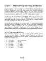
Chapter 7: Radio Programmi ng Software
If yo u are go ing to be programming a lot of repeater frequencies and
D-STAR access ca ll signs into you r radio, you shoul d defini tely
consider purchasing programming software for your radio. Not only
is it much easier to do, yo u might be able to import programming files
from others that can significantly simplify setting up you r radio.
Another plus for programming software is that once yo u have you r
radio setup, a copy of your radio' s frequency memories and setup
menus can be saved to yo ur computer. This can be a lifesaver should
you need to reload your radio for any reason.
Besides the software itself, an interface cab le for connecting between
the radio and your computer is required. Most of the time, a standard
RS-232 PC serial port is used on the computer side. However, on the
radio side, the connector is often unique to the radio. Frequently the
required cable comes with the purchase of the programming software.
leom 's Programming Software
leo m provides programming software (freque ntly called clon ing
softwa re) for the ir radios. The following list identifies the software
packages used with Icorn' s D· STAR radios. Most of these come with
a cab le, but some do not.
•
•
•
•
•
•
IC-9 IAD
IC-92AD
IC-Y82
IC-2820
IC-2200
IC-D800
RS-9 1 software
RS-92
CS-Y82
CS-2820
CS-2200
CS-D800
Page 67
RT System's Programming Software
RT-Systems al so provide s radio-programming software for radios of
all type s. Their software kits generally come with the req uired cab le.
Here are the RT part numbers for the software kits used with loom' s
D-STAR radios
•
•
•
•
•
IC-9I AD
IC-92AD
IC-2820
IC-2200
IC-D800
WCS-9 1
WCS-92
WCS-2820
WCS-2200
WCS-D800
I have not used any of RT System ' s software for D-STA R radios, but
have used their programs for severa l conventional transceivers. The
software I've used was reliable and did the job . Their software is
geared towards progra mming yo ur radio and does not include the
"vi rtual radio" features discussed below .
teem's RS-91 and RS-92 Programming Software
Most a ll programs prov ide similar programm ing functionality; some
of them go a step beyo nd. Here we will review the features of lcom's
RS-92 (Remote Control) software application as an example of what
can be do ne with one of the more enhanced programming packages.
Unlike most other programming software packages, the RS-9 1 and
RS-9 2 software packages have the capability of actually controll ing
the radio via a "v irtual radio" looking scree n. Using this " virtual
radio" is quiet similar to using a remote front panel, the co nnected
radio responds j ust as if yo u were pushing directly on the radio's front
pane l buttons. In general, radio-programming software packages do
not have this "virtual radio" capab ility; it is limited to lcom' s RS,
Remote Control series of software. Icom ' s CS series Cloning
Software is more ty pical of what is usual ly avai lable for program ming
radios.
Pa ge 68
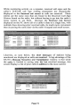
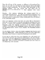
When the RS-92 program is started, it comes up with the "virtual
radio" screen. The first thing you need to do is click on the Option
pull-down menu and select the PC COM port that you will be using.
The program will read the radio' s current settings, which takes a
second or two, then the "virtual screen" will display the same
information that is being displayed on the radio's screen. While the
computer is reading the balance of your radio' s settings (called
synchronizing), the () button near the top of the display will be red;
synchronization is complete when it turns black.
~
a x
To examine or edit the radio' s memory, wait for the synchronization
button turns black) and click on the View pull-down
to complete
and select Edit Memory Chann el and the Memory CH screen pops up.
At the left side of the screen, a series of folders and sub-folders are
displayed in typical Windows format. These folders contain all ofthe
memories, setup menus and other parameters that can be programmed
on the radio.
«()
Page 69
The frequency memory channels are partitioned into two folders A
Band and B Band, within these two folders the memory channels are
displayed in 100 channel increments. Only the B Band can be used
for DV mode operation. The two screenshots below shows a
selection of memories from the first group of memories in the B Band
/ ALL folder. These screenshots are segments of a wider display as
seen on a PC.
~ ~§.~ , ·OUP ,
5_<lOllQQ.l~-,-OV
D--lOS
l~~OU P ,
O_~-,-
l).1~
151<
OV
~ie- Illl()()O
-------=-OY!·__,---.Jg11)~I(l() ,-1 ? 5:l'--,----l!'{ ----, !2:! 1
~~Ie-.~ (l()O , -DUP, 5 00999-,-! ~~,---l!'{---, _ l:l:"..!5
.i~]~.L--QUP ,
5 000Q0.J.L
~l!V , D--11S
~ ~~, -DUP ,
S OOOOO 1261<, OV ,0 1
co
~.~!~-,---PU.E.......! ~L l .~.~gCHO
~4.?l9<l9O-,----DUP ,
& ~,---1 2-";k----,-, ..CW
~Q.l > ~
, ~
~~!,?QOOO
----LPUP ,
. 0 1 >010B
5 (1)()jj() 12.51< OV
- -,-01>Ol OC
5.ClOCIO:IIl,..I~ .f1k..... CW..........01 > 011
5 00000.I ~~,_ ..i?:"
-----,-Ol> 015 B
5_000Q0....Jl5k r:N , 0 1 > 016
, ~
4H,,-~ , -OU P ,
~H ~
4H ~
-OOP ,
-COP ,
~ ~!..~~-OUP ,
, ~
5.00Q(l(U 2~..L- OV
,
'COCX)CQ
""
, ~
KI6NGN B
K!6MGMG
\" l, -rt,l,! h, __.......---i1 cc:lC:QC;Q_~1,e_!:l9,~ ,~, " __ .,~~~91,1,,~, .
~C.\ , -~h'~ ,
"
, <
I
I
BI
'.
•
-- ~
"~ '.-
., "'~n-. ~
, 1' ,11"',
~ ~ cr" ~
('" con- ~
,__ -,.-2::
COCOC:O__ ----L. ~I::I ,Fl.9 11 ,~_ . t:,'o'i'll ~ F\Cl ll
(" CQCQCQ
KI5KQUB
Kl6KQU G
(>: cXlgx~L_-----,~e_llFl.,II 11~B.R.Jl_(l
cc. CQC:X)C(.l .-----'-~ 6J '"'(l: .___' 1U6J ~.9
co KJtJ'A E
K11lJ'A B
l(l1lJ'AQ
".
",; -.
:". <
w<
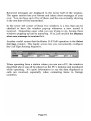
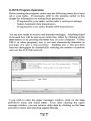
The above screenshots show the contents for memory channels 13
through 25, which have been programmed for D-STAR operation.
The upper one shows the repeater frequency settings, tuning step size,
operating mode and the name / label given to this memory channel.
The lower screenshot shows the D-STAR call sign routing parameters
set for each of these memory channels.
Page 70
Editing a memory channel, is a simple matter of clicking in one of the
cells, and making whatever changes you want, similar to making
entries on a spreadsheet. Some of the cells have a pull-down
selection menu, which is displayed if you hit Enter on the keyboard.
Pull-down selections are used for parameters that have several
standard settings, such as: Duplex, Tuning Step Size, Operating
Mode, etc.
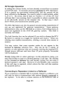
You can select setup menus or other memories to be viewed or edited
by either clicking on the file folders shown at the left of the screen or
by using the View pull-down selection menu. The following screen
shows the DV Set Mode menu sett ings, which are one of the sub
groups found under the Digital Setting group of menu sett ings.
D,g,tal Se mng
o Ff'lZj ": ~'~ ~ ~ ~
1
00
Auto
Auto
OFF
OFF
OFF
., GPS
" ,
§c:3A-G~J~~
_
5~
OFF
Like most PC applications, the File pull-down on the "virtual radio"
window allows yo u to save your settings to the PC and download files
containing memories and configuration settings to the radio.
O-STAR Operation Using the RS-92 Software
One of the great benefits of using the RS-9 1 and RS-92 software is
that you can actually operate the radio via screens on your pc. This
can be a whole new D-STAR operating experience.
Page 71
While monitoring activity on a repeater, received call signs and the
caller' s D-STAR call sign routing parameters are dyna mically
displayed in the Received call record as calls are received. These
entries are the same ones that are found in the Received Call Sign
History found on the radio, but without having to go into the radio' s
menu system to see them. Because the Received Call Record
displayed on the PC shows all of a caller' s data on a single line, with
multiple lines showing prior received calls, its much more convenient
than accessing the same data via the radio' s keypad and small screen.
,
I: C.II.,
"
I , ."".,
'=~
--~~
, K16l(Qt! G
" ",6I< QU G
1
' Col . r ""' ''
W06l'Z~
,
,
CQCQCQ
V60 Af
,=,
WCQZ~
CQCQCQ
CQCQCQ
CQCQCQ
V1WlIJ
;h ~ m
<16" QUG
<16KQUG
."KQ'.a
u • • QUG
KltiKQO I
. lti. QO G
' l '~ QU G
Kl• • QVIi
,
~.
RP1'r w&'-""" S' O\IifWR__ ~ ·c.
. 16t(QU8
KI6l<Q0 8
KI"'QOe
Kl6l<QUI
KI6l<QO I
KIlJ<Q;U I
<l"", w e
KI"",Qvt
" . ,
-
.
lev
'EMir s ..
f
;9'l'""
OOIIIlnoot 19,n '1I
.~
O4/IIZI2OO9
U'~:lJ
O</OZ/ZOO'I u,il<I,o'
.~
.
~
O<IOlnoot 1I,JI, 3O
'l<lllZI<'oot
'I<IIIZ/ZOO'I U,:lO,:/9
U,J7,.,
lloIIOm_U,lO'OO
../-., .... ..,..,..
~
;J
Likewise, as seen below, the short messages of stations being
monitored are displayed as calls are received. A big advantage of the
RS-92' s Message Recept ion and Transmission window is that while
the radio is limited to saving only the last received message, this
screen displays a list of prior calls in addition to the most current.
Ceh o
KC8YQl
K6DAf
I WB~YES
"
IONGl
!DO'.
' Ma H e \l e
BILL,CONTINENTAl,OM
SAN DIEGO HOIl.TH CO.
SAN DIEGO NORTH CO.
192AD
Page 72
Received messages are d isplayed in the lower half o f the window.
The upper section lets yo u format and select short messages of your
own. Yo u can have up to five of these, and the one curre ntly show ing
is the one that wi li be transmitted.
In the lower left co mer of these two window s is a box that can be
checked to have the w indow pop-up whe never a new record is
rece ived. Depe nding upon what yo u are try ing to do, having these
windows popp ing up can be annoy ing. If so, j ust unclick the Displays
when new message is rece ived box .
Another useful scree n that facil itates D-STAR operation is the Select
Call Sign w indow . This handy screen lets yo u conveniently con figu re
the Call Sign Routing Registers.
When operating from a station where yo u can use a PC, the windows
described above can all be placed on the PC' s desktop and monitored
while operati ng. It' s qu ite inform ative to see the data d isplayed as
calls are receiv ed, espec ially when contacting hams in fore ign
cou ntries.
Page 73
Page 74
Chapter 8: DV Mode Slow-speed Data
loom' s D-STAR compatible VHF and UHF transceivers come factory
ready for 1200 bps data communication. All you need is an RS-232
interface cable for connection to a PC, some data communication
software and you're in business. In general you can use the same
cable that is used to progra m yo ur rad io.
Cables for different model transceivers are available from learn, or
you can make yo ur own . Information for fabricating yo ur own data
cables can be found at http ://epaares.org/dstar/icom_cables.htm.
DV mode digital data can be sent simultaneously with voice
transmission. As explained in Chapter 1, the basic D-STAR digital
packet structure has space reserved for data and voice in the same
packet. DV mode transmission consists of a continuous stream of
digital packets for as long as you are transmitting. Even when you
are not transmitting data, the packet structure still includes space for
the data. Voice and data transmission on the same signal are
inseparable, even though one or the other are may not be used. As a
result, voice communication is not adversely impacted while data is
being sent at the same time. Conversely. data throughput does not
increase when not transmitting voice.
Data transmission through the D-STAR system is software and
protocol independent. To software applications, the PC' s data path to
the originating transceiver, through the repeater' s gateway to the
Internet and on to similar equipment at the other end, appears j ust like
a cable. Even though the data path is complex, software running on a
PC is not involved with any of the packet formation or routing issues.
All of that is handled by the transceiver and the gateway . The PC's
software only sees a stream of data bytes, stripped of all packet
header and routing information.
Since the entire data transport pathway, as complex as it is, appears
no different than a cable to software applications, existing terminal
emulation or data transport programs can be used without
modification. Familiar programs such as Hyper Terminal, found on
Page 75
most PC' s, and ProComm, a long time favorite for modem
communication, can readily be used. The catch is that the user at the
other end has to either use the same program, or one that is at least
compatible with the data that is being sent by the originating program.
D..sTAR Oriented Data Communication Software
Of course, hams are never satisfied with j ust making do with what is
readily available. Several have developed D-STAR data
communication software applications that seek to improve
perfonnance and capab ility beyond programs originally developed for
old-style modem communications. While there are a number of 0STAR data communication programs out there, the two most popular
seem to be d*Cha/ and D-RATS.
d*Cha/ (D-STAR Chat) is a simple to use Windows based keyboardto-keyboard communication application. Keyboard-to-keyboard
communication on D-STAR is somewhat similar to using RlTY or
PSK3 1, except text data is transmitted a line at a time. This is
probably the program to use if you want to experiment with
keyboard-to-keyboard communication with a friend or two.
D-RATS on the other hand, while still capable of keyboard-tokeyboard communication, sports a much more extensive list of
features such as: file transfers, GPS position reporting and mapping,
message filtering, email reception and forwarding and even a method
for creating and using forms. Several premade forms can be used for
sending eMail, radiograms and other purposes. Also included are
several sample forms for supporting EMCOMM incident
communications. Existing forms can be edited to suit your purposes,
or you can create your own. D-RATS is a multi-platform application
that can run on Windows, Linux/UNIX and MacOS X operating
systems.
Page 76
Radio I PC Configuration for Low-speed data Operat ion
Setup for low-speed data operat ion is relatively simple. Other than
configuring the PC communication software application that will be
used, there are three things to be conce r ned about on the radio:
• Serial port settings
• Selection of Automatic or PIT triggered data transmission
• Disabling GPS transmission
Configuring Serial Ports
The serial port data rate for some Icom transceivers is fixed; for
others it can be set via a setup menu. This chart identifies serial port
data rate setting capability by radio model.
Radio
Fixed
Use Menu
Model
IC-2820
IC-92AD
IC-91AD
IC-V/U82
IC-2200H
Data Rate
9600 bos
38.4 kbos
38.4 kbos
to Set
na
na
na
9600 bos
9600 bos
9600 bps
1D-800H
The PC' s serial port
parameters as follows:
• Baud Rate
• Data
• Parity
• Stop bits
• Flow control
na
na
na
must be set to match the radio' s serial port
Set as per the above chart
8 bit
none
1 bit
Xon I Xoff
Typically the PC' s serial port parameters are set using the PC' s
communication software application.
Page 77
Automatic I PIT Data Transmiss ion Selection
On a ll D~ STAR compatible leom radios, except for the IC-V!U82
there is a menu for selecting either Automatic or PIT triggered data
transmission. PIT is typically the radio' s default co ndition, and
limits data transmission to when the microphone's PIT key is
pressed. When set to Auto, the radio will start transmitting data
wheneve r it shows up from the PC' s co mmunication software
application. (The IC-V!U82 is fixed to operate in the Auto mode.)
Typ ically when transmitting data, the radio should be set to
automatically initiate transmission whenever data is received from the
PC. But you need to kee p in mind that when operating over a
repeater, espec ially if you are linked to a reflector, that the PC will
send data whenever it has it. If sending GPS position data or
operating other "beacon" modes this can be a problem because it can
collide with other user' s transmissions. In the case of sending GPS
position data, the PIT menu optio n should be selected to prevent
continuous " pinging" of the repeater.
The procedures for selecting either Auto or PIT data transmission for
the IC-91A D, IC-92AD and the IC-2820 are shown below. Cons ult
the lcom user manual for the IC-2200H and the 1D-800H.
Au tomatic 1PTI Selection o n th e IC-91AD and
lC~92AD:
1. Starting with the DV operating mode selected and a D·
STA R repeater frequency being displayed on the screen.
2. Press [MENU], which brings up the menu list.
3. Rotate [DIAL] or use [ .... ] I [ "] to select DVSET MODE.
4. Press [II>] to the DVSET MODE menu.
5. Rotate [DIAL] or use [ .... ] I [ T] to select DV DATA TX.
6. Press ( II>] to the DVDATA TXopt ion setting screen.
7. Rotate [DIAL] or use ( .... ] I ( "] to select either PTT or AUTO.
8. Press [MENU] to exit and return to normal operation.
Pa ge 78
Automatic I PIT Selection on the IC-2a20:
I. Starting with the DV operating mode selected.
2. Press [F] to access the function keys
3. Press [MENU] to select the MENU screen.
4. Rotate [MAIN- BAND] to select DV SET MODE screen, then
press [MAIN- BAND].
5. Rotate [MAIN- BAND] to select DV DATA TX, then press
[MAIN· BAND].
6. Rotate [MAIN- BAND] to select either PTT or AUTO.
7. Press [BACK] 3 times to exit and return to normal
operat ion.
Disabling GPS Mode Transmission
To be able to transmit slow-speed data with the IC·9IAD, IC-92AD
and IC-2820 transceivers its first necessary to tum off GPS mode
operation, otherwise the radio will not transmit. For other radios,
consult the learn user manual to see ifGPS needs to be turned off.
Disabling GPS Transmission on the IC-91AD and IC-92AD:
I. Starting with the DV operating mode selected and a D·
STAR repeater frequency being displayed on the screen.
2. Press [MENU], which brings up the menu list.
3. Rotate [DIAL] or use [.... ] / ["] to select DV SET MODE.
4. Press [ ...] to the DV SET MODE menu.
5. Rotate [DIAL] or use [ ...] I [ " ] to select GPS TX MODE.
(On the IC-9I AD select GPS MODE)
6. Press [ ...] to the GPS TX Mod e option setting screen.
7. Rotate [ DIAL] or use [.... ] / ["] to select DISABLE or OFF.
8. Press [MENU] to exit and return to normal operation.
Page 79
Disabling GPS Transmission on the IC-2820 :
1.
2.
3.
4.
Starting with the DV operating mode selected.
Press [F] to access the function keys
Press [MENU] to select the MENU screen.
Rotate [MAIN- BAN D] to select DV GPS screen, then press
[MAlN· BAND] .
5. Rotate [MAIN- BAND] to select GPS AUTO TX, then press
[MAlN·BAND] .
6. Rotate [MAIN- BAND] to select OFF.
7. Press [BACK] 3 times to exit and return to normal
operation.
d*Chat Application Installation and Setup
d *Chal, written and maintained by Brian Roode, NJ6N can be
down loaded from his web page http://nj6n.com/dstar/dstar_chalhbnl
Installation is simple and stra ightforward following the instructions
found on the web page. I downloaded the program to my computer
by clicking on the link in step 3 of his instructions, which seemed like
the simpler of several options presented. The program downloaded is
a .zip file that you can extract to some conve nient location. It installs
much like any other Windows application and places a dChat2
program entry your computer 's Start, All Programs list
Start the program by clicking on dChat2 in the All Programs list
When the dChat nj6n window comes up, click on Settings at the top of
the screen to display the Settings window. Here you can enter your
Call Sign and set the Communications Port Settings by selecting the
COM port that is con nected to your radio and it' s baud rate. Set the
baud rate to one that is supported by your radio.
Page 80
Cnll Si n C<l mmuni""tin n Pori Se ttiogs
MYCALl
COI,n
v
38400
Yo
~ lllCoIor
11,"Color r
~~
T ime s tamp
O lliS '"
~8ulfe< g
T
elay
151lO ms
S hnw ASClI
10 fill'" Duplicate
'''''II'' A.... l"'" R...tio Auoci"'ion
"_. I O "'~ . ""
C..atom S"on".
..
M"n ",,,
""
Save
The txColor and rxColor buttons are used to set the color for text that
appears in the text box on the main screen. I selected red for transmit
and blue for receive. The Font button selects the font style for text
that is displayed.
The Settings screen contains two areas for pre-formatting messages
that you want to send. In the QST Message area, text that is to be
broadcast on a periodic basis can be programmed. If you want to
broadcast QST messages, set the Minutes pull-down to a suitable time
between broadcasts. In the screen above, its been set to once every 30
minutes, and then check the Send Periodic QST box. Since this will
periodically ping the repeater, you want to be careful about using this.
The Quick Send Text Messa ges area allows you to program up to
seven different messages that can later be easily recalled and
transmitted. These are intended for messages that you might use on a
Page 81
regular basis. Th ese coul d be for send ing a CQ, instruct ions on how
to reply to yo ur call, station ident ificat ion, equipment setup and so on.
Once programmed, these messages ca n easi ly be transmitted from the
ma in screen at the click o f a button .
The Custom Banner Message box lets you custo mize the banner I
header that ap pears at the top of the main dChat screen. Here yo u
co uld enter yo ur own call sign, club identification, spec ial event
identification or anything else yo u m ight thin k of. Thi s is "w indow
dressing" and does not get transmitted .
Th e Logo button is more " window dressi ng" and lets yo u select a .j pg
image o f yo ur ow n to replace the logo displayed in the upper right
co me r of the Settings and main dChat screens.
When the Show GPS box is checked, incoming GPS I DPR S mes sages
will be displayed. If too many inco ming GPS messages get to be a
problem, unchec k the box to filter them out.
T he Filter Duplicate box lets you filter out rece ived duplicate
messages based upon the last two lines of rece ived data.
Normally the Buffer box is left checked, but if yo u need to see non
line-termin ated data (text run together without line break s), such as
might be rece ived from D-RATS, uncheck this box .
No rma lly the Show ASCII box is left unchec ked. If checked the
ASCII code repre senti ng the character w ill be d isplayed in
parenthesis followin g each character. This m ight be used for
tro ubleshooting or other purpo ses.
T he TxDelay box is used to set the maximum rando m delay that is
used between eac h line that is sent. A random delay is inserted to
help avo id collision s (s imulta neous transm issio ns w ith other stations).
Norma lly the default setti ng of 1500 ms should be fine .
When yo u are fini shed w ith the Settings screen, be sure to cl ick the
Save button at the bottom to save you work. To go bac k to the main
dChat screen, click on the Settings button .
Page 82
d*Chat Program Operation
Before running the program, make sure the following items have been
set on your radio . If necessary, refer to the above sections for
information on setting these parameters.
• If required for yo ur radio, set the radio's serial port settings.
• Select Automatic data transmission
• If required for your radio, disable GPS transmission
Once insta lled and setup, d *Cha/ is relatively simple to operate.
When started, the program displays the following screen.
...
-
~~
-
South Orange Amateur Rodio Association
www.soara.org
,•
2.'.'1<1200II100.. A...... N' GIl ~ .. .. ?
First, making sure your radio is connected and tuned to a D-STAR
repeater or DV mode simplex frequency, click ing on the Connect
button should result in a COMx opened port status being displayed j ust
to the left of the Recall button. (COM3 opened is shown above)
Page 83
Transmitting consists of sending some text by either typ ing in the
Text to Send box or by clicking on one of the messages in the Quick
Send box, which copies the message to the Text to Send box.
When the data in the Text to Send box is ready to be sent, click on the
Send button or hit the Enter key on your computer's keyboard . Data
is transmitted a line at a time.
If the text you sent is immediately echoed back, and the NO
DIALTONE error message is displayed, it was not actually transmitted
and yo u may not have selected the correct COM port or baud rate on
the PC.
If you wish to re-send the last line sent, press the Recall button.
If your text box starts to get cluttered, it can be cleared by clicking on
the Clear button.
Pre- formatted small messages can also be broadcast by selecting Send
Bulletin, under the File pull-down menu. This feature cannot be used
for file transfers. Instead, it is a way of pre-formatting sma ll multiline messages for transmission. Messages sent this way show up in
other users text window. just like any other messages .
Page 84
D-RATS Application Installation and Setup
D-RATS, written and maintained by Dan Smith, KK7DS has more
features and consequently is a bit more complex to use than ds Chat.
Dan actively encourages user input, periodically providing new
releases implementing changes requested by D-RATS users. The
program can be downloaded from his web page http://d-rats.com
Installation instructions and downloads are provided for the
Windows, MacOS X and Linux operating systems. Of the two
options provided for Windows installation, I took the simpler option
and downloaded and installed the binary release version of the
program, wh ich has everything needed for the installation packed into
a single zip file. Installation is simple and straightforward following
the instructions found on the web page. Unzip the down load to a
convenient location.
The program does not install itself into your computer's Start > All
Programs list, instead it' s started by accessing the folder you placed
the program in and clicking on the d-rats.exe file. For convenience
you can save a short cut to the desktop, or drag the d-rats.exe file to
your Start > All Programs list.
To setup the program, start the application and on the D·RATS main
screen select File > Main Settin gs, which display sthe Config screen.
- --
5io;J>-"" ~
0
~ 'Of*le~TS)
sq,.",,~ El ~ :Gcwn9o/rk'le$4lJ\TS)
,-
I,.... r...
iii'lllt..o<l:.
KPG.._
TQ> f~
lH:<
SlQy tme i'I lIT(
: ~
0
.
=
",
ft>Ibiod
I'w>< ,<ply
{ "'-
...-
0
P<,,"""<W....
..._.•........_...
Er>obIe<l
out~Emol
1<><Oll'ilijErMoI
E",""I'<ce<s
Page 85
ty
~I
Under the Preferences section, enter your Call Sign and Name. When
the Sign-on and Sign-off Message boxes are checked, short messages
are automatically transmitted, indicating whenever you open and
close the D-RA TS program. Uncheck thc boxes if you don't want
these messages transmitted every time you start the program.
On the same screen you will also see the Ping reply box. When
another D-RATS user issues a Ping Station command, either to a
specific station or all stations via CQCQCQ, any online D-RATS
stations will automatically respond with an answer. This is where
you can program your own reply to a ping. Typically this might be
your call, location, a greeting, equipment setup or anything else you
desire.
If you intend to perform file transfers, under the Preferences section
click on Paths to set a file folder to which incoming files will be
downloaded. The default Download Directory setting places them on
the desktop. You will notice that you can also select a folder for
where maps will be stored.
Also under the Preferences section, by clicking on GPS you can either
enable an attached GPS unit, or set a fixed Latitude, Longitude and
Altitude. If you don't attach a GPS, providing you are connected to
the Internet, you can easily set the Latitude and Longitude by clicking
on the Lookup button and entering an address, zip code or an
intersection. If connecting an External GPS to your computer, check
the Use External GPS box to enable it and select the COM port and
baud rate to be used.
.
Initially, you can use the default settings for Appearance and Chat
under the Preferences section
Next, click on the Radio section to set the computer's Serial Port and
baud rate setting. Set the baud rate to be the same as being used on
your radio. The other items under the Radio heading can be left at
their default settings.
Click on Save to save your settings and exit the Config screen.
Page 86
D-RATS Program Operation
Before running the program, make sure the following items have been
set on your radio. If necessary, refer to the sections earlier in this
chapter for information on setting these parameters.
• Ifrequired for your radio, set the radio's serial port settings.
• Select Automatic data transmission
• Ifrequired for your radio, disable GPS transmission
You are now ready to receive and transmit messages. Anything typed
in the send box will be sent as an entire line, either by clicking on the
Send button or by pressing the Enter key on your computer. Unlike
PSK31 or other programs, text is not sent character-by-character as
you type; it' s sent a line-at-a-time. Sending text a line-at-a-time
improves throughp ut by dramatically reducing the number of packets
sent over the D-STAR network.
I>
My UlJ: Nt;HV
12:56:33:
CQ de NSfN, If yoJ can copy ttlls, please r€pty.
13:08 :10:
>
testiloJ
,
13:22:30:
> CQ CQ do> f'ffN, resec cats mcce with £>-RATS
My 0JIl' /\tRV
"
r;
~
"..
.
"
I
CQCQdolll6ffl, fYOUC¥lC"P\'\M, p/eaM,epIy,
IIl6ffl, Te<tlr>g dota _
With c-AATS.
~I
If you wish to clear the upper messages window, click on the View
pull-down menu and select Clear. Even after clear ing the upper
message window, you can retrieve older data by clicking on the View
pull-down menu and selecting Log for this tab .
Page 87
If you wish to pre-format short messages that yo u might use on a
regular basis, select File, Quick Messages, which displays the Quick
Messages editing screen. Here you can enter, edit and re-arrange
messages for later use. Quick messages can be transmitted by
selecting the Quick Message tab on the main D-RATS' screen and then
double clicking on the message you want to send.
rJ
EC Quick Messages
N6FN, Testilg date mode with t>RATS.
CQ CQ de N6fN, I you ( an
( op),
tbs, please reply. Jhllr»;s.l
II
"""
II
To determine if any other stations are online, you can send a ping
command, and any connected D· RATS stations will respond with the
reply that was set in their station's configuration setup Ping reply box.
The Ping Station button is found under the File pull-down menu. You
can ping specific stations that have been recently been heard by using
the pull-down box, or by entering the stations call directly into the
box. Enter CQCQCQ in the box to receive replies from any stations
that are online.
Page 88
Configuring and Sending D-RATS aST Messages
QST messages can automatically be transmitted on a periodic basis.
To pre-format QST Messages, click on the File pull-down menu and
select Auto QST Settings, which brings up a screen for creating the
message and selecting the time-to-delay between transmissions.
( ..-.col
ae
"
Jt
II ......
'1•"'"
Checking the Enabled box selects the QST Message to be transmitted.
Upon saving yo ur settings and closing the .screen, providing File,
QSTs Enabled has been selected; the message will be transmitted at
the selected time intervals. While the QST Message is being
displayed in the QST Monitor window, you will see it counting down
the transmission timer. If yo u wish, the message can be immediately
sent by double clicking it, handy for bypassing the full time period
when testing.
Page 89
Transferring Files with D-RATS
Under the File pull-down menu, there are three different options for
initiating file transfers: Broadcast Text File, Send File and Send Image.
When clicked, these three options allow you to browse to where the
file to be transmitted is located, so the file to be sent can be selected.
Use Broadcast Text File, when you want to transmit a pre-formatted
text message that you have created. As the name suggests, this is not
a true file transfer because the file is being sent and received as if it
was text data that was typed. You can create this file with any text
editor, such as Windows Notepad or Word pad. You don't want your
message to contain hidden formatting control sequences that are
inserted by word processors. If you do use Microsoft Word, or some
other word processor, save the file as a .txt file.
Send File allows you to actually transmit files that will be received as
a file by the receiving station. When the file comes in, D-RATS will
place it in the location specified by the Paths, Download Directory
box found under the Preferences section of the Config window. lf you
send files on a regular basis, press your computer' s F1 key as a
shortcut to using the Send Fileoption on the Files menu.
The Send Image selection, true to its name, is' used to send .jpg .gif
and other types of image files. Be careful with sending images, as
files can be quite large and may be unsuitable for transmission via DSTAR' s low-speed DV mode.
Page 90
File Transfer Problems
If text and quick messaging are working fine, but you are having
difficulty transfering files, you might try the following to solve the
problem.
Data Block Transfer Problems: Best throughput performance will be
had with larger block sizes. If you are having trouble completing file
transfers, a high block size may prevent you from gett ing blocks
through. Reducing the block size reduces the odds of incurring errors
within the block, which may reduce file transfer difficulties.
To change the default block size select Main Settings under the File
pull-down menu, and then select Radio, Transfers, on the Config
screen. The program default block size is 5 12, which is relatively
large. To see if smaller block sizes can alleviate block transfer
problems, you might try block sizes of256 or 128.
Mixing File Transfers with voice: This is from the D-RA TS web page.
"Because of the effect timing has on the ability to detect failed or
missing blocks and retry, interrupting a file transfer can cause
problems. Talking on the digital voice side while doing a file transfer
will prevent the proper negotiation from happening in a timely
manner, and may cause the transfer to time out. Try to avoid talking
while sending a file if possible."
Page 91
Using and Creating D-RATS Fonns
There are a numbe r of pre-made forms avai lable. To view ava ilable
forms, cl ick on the File pull-d own menu and select Manage Form
Templates, wh ich display s a ll available forms . Click on one of the
forms in the list and then cl ick on Edit, wh ich d isp lays the Form
builder window. The Form builder w indow allows you to create or
ed it fonn s. Cl ick on Preview to view the selected fonn . After
exam ining the forms, click on Cancel tw ice, and then cl ick on Close
to return to the main O·RATS w indow.
To se lect a pre-made fbrm, so it ca n be filled o ut, from the main O·
RATS window select the Form Manager tab and click on New, wh ich
displays the Choose a form w indow . Select one of the fonns using the
pul1-down box and then click OK to d isplay the form. Now it can be
filled out and then: saved, sent, ex ported to a file folder, or printed.
If yo u wish to create you r own forms, under the File pull-down menu,
use the Manage Form Templates button to access the Form Manager
w indow. From this scree n you ca n eithe r edi t and rename an exi sting
forrn, or build one from scratch. To learn how a form is created or
edited, click on one of the existing fonns to highli ght it and clic k on
Edit to open it. So you can freely experiment without modi fy ing the
original fonn, use the Form builder window and change the name in
the 10 box to something else and Save it as a test fonn. Now using
th is as a test form, close ly exa mine its Form Elements , modi fying
them and adding new ones to learn how the form was created .
Periodically use the Preview button to evaluate your mod ifications.
After some experimentation you will learn how to ed it and create
you r own fonn s.
Page 92
Stations and Sess ions Tabs
The Stations tab allows you to see the call signs, and G PS position, if
sent, of stations that have been received. Stations can be de leted from
this list via the Remove and Clear All buttons. C licking on Address
places the station's call sign in the Send text box. When you cl ick on
one of the stations in the list, it becomes highlighted, press Forget if
you wish to reset the Last Seen time stamp to Never. If you press
Reset, a selected station's Last Seen time stamp is set to the current
time.
The Sessi ons tab can provide current status of transfers in progress
and other informat ion. When transferring files, it' s instructive to see
the file transfer' s progress displayed on this page, especia lly if you
are havi ng file transfer difficultie s.
Other D-RATS Capab ilities
The above sections describe the main features and functiona lity of the
D-RATS application ,
However, there are other features that
adva nced users may find of interest.
Ratflector: As described on the D-RATS web page, http://d·
rats,danplanet.comlwiki/Ratflector the Ratflector is ava ilable for
testing and asking questions of users that may be connected.
Accessed via the Internet, the Ratflector is a non-RF connection that
a llows you to test and expe riment with the various D-RATS modes of
operation. Instead of ro uting data out a COM port to the radio, it is
sent over the Internet. You can do ju st abo ut everyth ing that you
would normally do over the air, but in this case the data packets are
transferred via the Internet. Using the Ratflector, you could exchange
data with a friend, or use two computers side-by-side to simulate two
stations intercommunicating.
Page 93
Internet email: D-RATS can be used to send and receive emai l to
and from the Internet. A D-RATS station can be set up as an email
server, so that stations withou t a direct Internet connection can still
rece ive and send ema il messages. Emails are created and retrieved via
the D-RATS Form Manager. Further informa tio n can be fou nd on the
D-RATS web page: http://www.d-rats.com /wikillnternetEmail
TCP Forwarding: From the D-RATS web page: " D-RATS has
generic TC P forwa rding support. This means yo u can pipe some TCP
traffic acro ss the radio to a remote station. This may be useful for
bridg ing SMTP traffic to a remote location or for do ing POP) for
remo te mailbox access. In it's native form, this will be rather slow,
given that most of the protocols likely to be used in this fashion are
very chatty and depend on a lot of back-and-forth handshaking to
complete. While you should be prepa red for this, the functionality
should still be quite useful." Further informatio n can be foun d at:
http://www.d-rats .com/wikifTcpForwarding
D-RATS Repeater Operation: D-RATS also has a repeater program,
which can be used as a repeater with multiple radios, or as a networ k
proxy (instead of or in add ition to the repeater function). Furthe r
information can be found at: http://www.d-rats.comlwiki/Repeater
Connecting D-RATS to a DPRS Interface: Two separate pieces of
software, D-RATS and DPRS Interf ace developed by Pete Lovea ll
AE5PL, can be configured to operate simultaneously across a 0STA R radio' s low speed DV channel. DPRS Interface is designed to
pass GPS-A DPRS messages received from a D-STAR radio's low
speed DV channel and pass them on to the APRS-IS netwo rk where it
is combined with A PRS and DPRS traffic wor ld-wide. As many
internet connected D-STAR repeaters already have an ope rationa l
DPRS > APRS-IS interface, the D·RATS interface is only. intended
for use in cases where that con nectivity is not ava ilab le. Further
information can be fou nd at:
http://www.d.rats.comlwiki/DPRS-lnterface
Page 94
Chapter 9: DV Dongle, D-STAR Adapter
Besides being a solution for hams that don't have local access to a
gateway equipped D-STAR repeater, the DV Dongle is fantastic for
quickly and easily connecting to gateways and reflectors all over the
world. It' s espec ially suited for situatio ns when you are out of town
and wa nt to get back in to you r local repeater.
Developed by Robin Cutshaw, AA4RC and Moe Wheatley, AE4JY,
the DV-Dongle prov ides an alternative method for participating in DSTAR communications without using a radio.
Housed in a small semi-transparent blue plastic enclosure, the Dong le
connects to your computer's usn port via a short interface cable.
Since wo rld-w ide D-STAR comm unications are facilitated by sending
digitized voice packets over the Internet, the only thing a PC needs to
be able to participate in D-STAR communications is some suitable
software and a means of encoding and decodi ng D-STAR ' s digital
voice streams. Taking advantage of a PC' s high speed USB 2.0 data
port, circuitry inside the Dong le uses an AMBE digital voice CODEC
to encode and decode voice data streams to the D-STAR protoco l.
Robin Cutshaw's, DV Tool software than takes care of transporting
these data streams back-and-forth over the Internet to remote
gateway s and reflectors .
Page 95
Computer System Requirements
The DV Dongle applicat ion needs a relatively fast computer to run
properly. It' s recommended that you have a 2 GHz or faster machine,
and turn off any compute intensive applications to preve nt data
ove rruns between your co mputer and the Dongle. The Dongle's red
LED flashes whenever overruns occur. I first tried installing on an
older I GHz system, and performance was unsatisfactory. Operat ion
o n my Intel Dual Core 1.6 G Hz laptop was quite usable, with
infrequent overrun s.
In addition to a fast compute r, you also need a high speed Internet
connection. Dial-ups will not work. The Internet service that comes
bundled with my cable TV subscription worked fine.
If you don't already have one, you will need a headset and
microp ho ne that is compatible with the audio jacks on your co mputer,
typically 3.5mm ( l i S") audio jacks. There are a lot of inferior quality
headset I mic products being sold for the mass-consumer PC marke t;
for optimum voice reception and transmission you will want to get a
higher quality unit. Most of the cheap units have sma ll ear cuffs that
don't block out ambient noise and quickly become uncomfortable to
wear.
Installing the DV Dongle Software on You r Computer
After purchasing a Dongle, the latest version of the D V Tool software
is downloaded from the DV Dongle web page.
http://dvdongle.com/DV_Dongle/Home.html
Clicking on the Installation ta b accesses installation instructions and
sample screen shots. Instructions and different software dow nloads
are provided for the Microsoft Windows, Mac OS X Leopard, and
Linux operating systems.
Page 96
Note that on Windows systems, inserting the Dongle will bring up the
Found New Hardware Wizard to assist you with installing the
required USB drivers. Installation of USB Drivers on Microsoft
Windows is a two-step process, bringing up the Found New
Hardware Wizard two times. Make sure you complete both installs.
After installing the USB driver, you can download the DV Tool
software application to a suitable place on your computer. The web
site instructions suggest you download and extract the files to your
desktop. Preferring not to do that, I downloaded them to a DVToul
sub-folder I created in my Program Files directory, which is where I
keep all my other applications.
After extracting the files by unzipping them to whatever location you
prefer, the application is started by double-clicking or opening the
DVToolJar file found in the DVTools folder. Rather than having to
open the folder whenever you want to run the program, you might
want to put a shortcut to the program on your desktop or in the PC' s
START menu.
On Windows, to place a short cut on the desktop, right click on the
DVToolJar file and select Send to Desktop from the pull-down
window that pops up. To insert a shortcut into the START, All
Programs menu, drag the D VTool.jar file to the START button; wait
until the All Programs option shows, and then drop/place the shortcut
where you want it to appear in the list of programs.
Select ing the DV Tool COM port and Audio Devices
On the DV Dongle home web page; select the Using the DV Dongle
tab to access the operating instructions. Before starting the DVTool
program, make sure the DV dongle is plugged in. Upon starting the
program verify that the serial port showing in the DV Device window
is correct. lf'not, select the correct one from the pull-down list.
Page 97
~
D OVTool
f ill
Help
OVOong le
O Relool e Hnst: ;',l 'r'Ot t
OlMee Nam e:
fllf" ..", eV IIS'<!fl:
Serial NI..,I>ef;
1,;,.,,1•• "".;.
Aud ,o Inpll:
I~
I~
Next verify that the Audio Input and Output devices selected are the
ones you want to use. If unsure, leave the default settings for now,
you can come back to this and try other settings while doing Audio
Loopback testing.
Click on Open to establish communication with the DV Dongle
hardware. If all is well, you should see the Device Name, Boot
Version, Serial Number and Finnware Revision fields filled in as shown
below. If communication was not established, you may have the
wrong COM port selected. Try a differen t setting.
fill Help
DV OO llgle
DV DfNi u:
DRell1Ole llol,t
Df!W:" Nd" l/!';
;0"-
IN Dongle
Serial No" ....... ; DVOS1518
AudIolnpul:
Au<lio 0tIl1'Ut:
"J:;:
IlO<ltVen Jon;
1.04
k'n"'",eV... sion: 1.11
R
~!'.~~.~'.~, ~•.~..~.~~~~~~~~~~~~
H_
.~ .~""..
hi A.f"
Page 98
Setting the Headset and Microphone Audio levels
Open your computer system' s Volume Control settings window,
usually accessed by right clicking on the speaker icon found in the
system tray, at the bottom right of the computer screen.
Before setting the record level, you should first set the headset
volume level for comfortable monitoring of other D-STAR station' s
transmissions. Once that is set, you can then set your microphone
recording level to match received D-STAR signal audio levels. To do
this we need to monitor some D-STAR activity.
Click on the Connect to Gateway button and select aD-STAR
gateway with some traffic. Thi s could be your own local gateway or
a reflector, or a distant repeater. Next select the repeater' s Module, if
just looking for traffic, select the asterisk to be able to hear traffic
on any of the modules. If you have not already done so, enter your
own call sign in the Callsign box. By the way, even though you don't
transmit, your call sign will be picked up by the D-STAR system and
displayed as monitoring the selected repeater or reflector.
*
,-
o AMB:EIAudio loopbac k
o Playba~k
o Audio l oop/l<tCk OnlV
o Racord
o Re~"' d IOne
0
Playba~k from file
.."~. t:: ===C I..." I
C
Coru~ loPellf
o listetl lo, Connect ion I,,,, n Pee ,
COl ll\E'Cl 10 Galew<'(f
Page 99
Once the call sign of the repeater or reflector to be monitored has
been set, and yo ur own call sign has been entered, click on the Start
button to begin monitoring. If you don't hear any traffic on the
selected repeater, you can access the last heard list at
http://dstarusers.org/lastheard.php to find repeaters with some
activity.
Monitor a few stations, adjust ing the volume control for a
comfortable listening level. As with conventional FM repeaters, you
may notice volume level differences between received stations. If
necessary, select a compromise volume setting that allows all stations
to be comfortably heard.
Once your listening volume has been set, press Stop to disconnect
from the D-STAR system so that the microphone recording level can
be set. To access your computer' s microphone level control, select
Properties under the Options pull-down of the Volume Control
window. This brings up the Properties window where you can select
the Recording button, which in-turn displays the Recording Control
window.
On the DVTool window, select the Audio Loopback Only function and
then press Start again. While listening to your own voice, adjust the
Microphone level control to match the listening level set earlier.
If you want to verify hear how your digitized voice will sound over
the D-STAR network and verify the performance of the DV Dongle,
press Stop, select the AMBEJAudio Loopback function and then press
Start again. Here it will be a bit easier to monitor yo ur own voice, as
it is delayed by a few seconds.
Page 100
DV Dongle Operation
In setting the volume levels, we have already covered how to monitor
a D~ S TA R node. To transmit, j ust press and hold the PIT I Rx button.
If it is grayed out preventing transmission, and the asterisk
has
been selected as the Module, you need to select a valid module, either
A, B or C. Be aware, that at least on Version 1.1 1 of the DV Tool
software that I was running, that it is possible to select a module that
is not physically present at the repeater site. In that case, I don't
know where your transmission actua lly goes.
*
The PIT I Rx button can also be grayed out preventing transmission if
you are not registered for gateway transmission. Some gateway
administrators may use the PIN field as a means of providing access to
users not registered in the D-STAR gateway system. This field is
normally left blank.
The lock function box can be selected if you wish to change the PIT /
Rx button to operate as a toggle for transmit and receive. When set,
clicking once enables transmission, clicking a second time returns to
receive.
You may notice, that some repeater nodes do not appear in the
Connect to Gateway selection box. This can be for a variety of
reasons, as only gateways that are currently running the required DV
Dongle access software and have their IP ports properly forwarded
will be displayed.
Besides being able to select gateways via the pull-down menu, you
may find it faster to type in a desired gateway's call sign. By clicking
on the Connect to Gateway box and quickly typ ing you can enter a
desired repeater' s call sign. However, if you hesitate, only a portion
of the call sign is captured, which selects the first call that matches
the accepted portion.
Connecting to Repeaters Linked to a Reflector
If you connect to a repeater that is currently linked to a reflector, you
will only be able to communicate with stations directly connected to
the repeater. To be able to contact stations on the Reflector side of
Page 101
the link, you need to disconnect from the repeater and connect to the
reflector that the repeater is linked to. Then you will be able to
communicate with any station or repeater linked to that reflector.
Dongle LED Status Indicators
Four LED indicators, visible through the semi-transparent plastic case
communicate the DV Dongle' s operat ional status. A blue LED
flashes whenever data is being transmitted from the computer and a
flashing yellow LED indicates that data is being transmitted back to
the computer. A slowly pulsing green LED indicates that the device
is idle. More importantly for assessing pcrfonnan ce, the red LED
indicates either data overruns or under runs between the computer and
the Dongle. Occasional overruns aren't too bad, but frequent flashing
of the red LED indicates a slow computer. Shutting down other
programs may help; otherwise you will need a faster system.
Installat io n Problems
A variety of problems can occur that will prevent DV Dongle
operation. One of them is not having a sufficiently current version of
Java running on your computer. If that is the case, the installation
instructions found on the DV Dongle web page guides you through
getting the latest Java updates downloaded.
Firewalls protecting your computer, network or router may prevent
the program from communicating over the Internet. Other problems
may arise with getting volume controls set, or being able to record
from the microphone.
If you are having difficulty, the Yahoo DV Dongle group found at
http://groups.yahoo.com/group/OVDongle may be able to provide
assistance. With hundreds of postings covering just about any type of
problem you can imagine, you should be able to find one that matches
your problem. If you can't find a solution in the threads that are
already posted, you might try registering and asking a question of
you r own.
Page 102
Appendix: D-STAR Web Pages
Here are additional D-STAR web pages that you mig ht find useful.
O-STAR Users, Source fo r O-STAR Information
http://dstarusers.org/lastheard .php has last heard lists, D-STAR
repeater directory, gateway registration links and links to D-STAR
acce ssory hardware and software and more.
D-STAR Information, FAQ's and More
http://www.dstarinfo.com/default.htm ID-STAR news,
applications, links, nets, reflectors and more.
K5TIT The Texas Interconnect Team
http://www.k5tit.org/ Repeater group in Texas, lots of useful
informat ion.
Instructions for Making leom Radio Interface Cables
http://epaares.org/d star/icom_cables.htm ' GPS interface and PC
programming ca ble-wiring diagrams for home made cables .
WY1U's O-STAR Repeater and Reflector Finder
http://ho me .c o mcas t.n eU-timm ikid s ta rsea rc h.ht m l good for
finding repeaters in different parts of the world.
APRS-IS I OPRS Information
http ://www.a pr s-i s .netJ operating information, APRS-IS acti vity,
APRS / DPRS conversion, software, specifications an d more.
Enab ling GPS Pos ition Reporting through 0-5TAR
http://nj6 n.com/dstar/dprs / translating learn GPS data to be
compati ble with APRS. Incl udes sample AP RS radio setup guides.
Yahoo D-STAR Forum I Group
http://groups.yahoo.com/group/dstar_ d ig ita ll D-STAR d iscussio n
grou p, problem so lving. and other topics
Page 103
Icom Tech Support Knowledge Base
http://www.icomamerica .com/en/suppo rUkb/Defau lt.aspx
Select the following pull-downs for all D-STAR articles.
Product line: Amateur
Product Class: D·STAR
Model: General
Balance of fields leave blank, Press Search
d*Chat Communications Software Home Page
http ://nj6n.com/dstar/dstar_chat.htmI Feature list, software
download, installation instructions.
D-RATS Communications Software Home Page
http://d-rats.com/Feature list, screenshots, software download,
installation instructions, user forum, FAQs.
D-StarCom Icom .lcf Radio File Conversion Utility
http://www.d-starcom.com/ Program for converting Icom .icffil es
from one radio type to another.
j Findu Home Page
http://www.lfindu.net Last heard lists, D·STARRepeater and DPRS
activity, D·STAR repeater locator map and more.
DV Dongle Home Page
Technical info,
Installation instructions, Software screenshots, FAQs
http://dvdongle.com JDV_Dongle/Home .html
DV Dongle Yahoo Support Group
http://g roups.yahoo.com /group/DVDongle
DV Dongle discussion and
support.
RT System's Programming Software
http://www .rtsystemsinc.comJinde x.cfm RT System's home page.
Radio programming software and cables.
Page 104