1
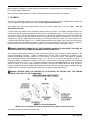
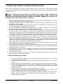
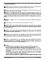
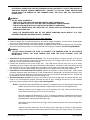
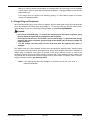
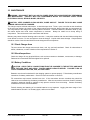
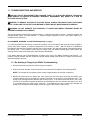
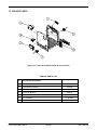
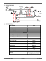
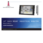
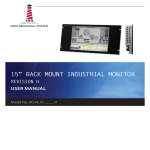
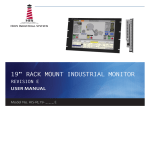
USER’S MANUAL
Model 26610
Important Safety,
Installation,
Operation, and
Maintenance
Instructions
www.LesterElectrical.com
TABLE OF CONTENTS
TABLE OF CONTENTS .............................................................................................................2
IMPORTANT SAFETY INSTRUCTIONS ...................................................................................3
NOTICE: .....................................................................................................................................5
1. SYSTEM OVERVIEW............................................................................................................5
2. CHARGER FEATURES ........................................................................................................5
2.1 CHARGE INTERLOCK ............................................................................................... 5
2.2 LONG-TERM STORAGE CHARGE ............................................................................ 5
3. BATTERY WARNING LIGHT ...............................................................................................6
4. RECEIVING THE CHARGER ................................................................................................6
5. STORAGE .............................................................................................................................6
6. LOCATION AND INSTALLATION ........................................................................................6
7. AC INPUT ..............................................................................................................................8
8. PROPER CARE OF DEEP CYCLE MOTIVE POWER PATTERIES ....................................9
8.1 PERSONAL SAFETY PRECAUTIONS ...................................................................... 9
9. CHARGER OPERATION .................................................................................................... 10
9.1 CHARGER PLUG AND RECEPTACLE ................................................................... 12
9.2 USER INTERFACE ................................................................................................... 13
10. MAINTENANCE ................................................................................................................ 14
10.1 CHECK CHARGER AREA...................................................................................... 14
10.2 VISUAL INSPECTIONS .......................................................................................... 14
10.3 BATTERY CONDITIONS ........................................................................................ 14
11. TROUBLESHOOTING AND SERVICE ............................................................................. 15
11.1 RE-STARTING A CHARGE CYCLE WHILE TROUBLESHOOTING ..................... 15
12. SERVICE PARTS .............................................................................................................. 16
13. WIRING DIAGRAM ........................................................................................................... 17
14. SPECIFICATIONS............................................................................................................. 17
LIMITED WARRANTY ............................................................................................................. 18
Links Series Model 26610
2 of 20
User’s Manual
IMPORTANT SAFETY INSTRUCTIONS
1.
SAVE THESE INSTRUCTIONS – This manual contains important safety and operating instructions.
2.
Before using battery charger, read all instructions and cautionary markings on battery charger,
battery, and product using battery.
LOOK FOR THIS SYMBOL TO POINT OUT SAFETY PRECAUTIONS.
IT MEANS: BE ALERT—YOUR SAFETY IS INVOLVED. IF YOU DO
NOT FOLLOW THESE SAFETY INSTRUCTIONS, INJURY OR
PROPERTY DAMAGE CAN OCCUR.
3.
4.
DANGER: TO REDUCE THE RISK OF FIRE OR ELECTRIC SHOCK, CAREFULLY READ AND
FOLLOW THESE IMPORTANT SAFETY AND OPERATING INSTRUCTIONS BEFORE INSTALLING
OR OPERATING THE CHARGER.
INSTRUCTIONS IMPORTANTES CONCERNANT LA SECURITÉ.
5.
WARNING: TO REDUCE THE RISK OF FIRE, INSTALL THIS BATTERY CHARGER ON A
SURFACE OF NON-COMBUSTIBLE MATERIAL SUCH AS BRICK, CONCRETE, OR METAL.
6.
DANGER: RISK OF ELECTRIC SHOCK. DISCONNECT CHARGER FROM BATTERY AND AC
POWER BEFORE SERVICING. TURNING OFF THE CHARGER DOES NOT REDUCE THIS RISK.
7.
DANGER: RISK OF ELECTRIC SHOCK. DO NOT TOUCH UNINSULATED PORTION OF AC OR
DC CONNECTORS OR UNINSULATED BATTERY TERMINAL.
8.
DANGER: RISQUE DE CHOCKS ÉLECTRIQUES. NE PAS TOUCHER LES PARTIES NON
ISOLÉES DU CONNECTEUR DE SORTI OU LES BORNES NON ISOLÉES DE L’ACCUMULATEUR.
9.
CAUTION: CHARGE ONLY LEAD-ACID BATTERIES. OTHER TYPES OF BATTERIES MAY
BURST CAUSING PERSONAL INJURY AND DAMAGE. BEFORE CHARGING ANY OTHER TYPE OF
RECHARGEABLE BATTERY, CHANGE THE CHARGER SETTINGS AS RECOMMENDED BY THAT
BATTERY MANUFACTURER.
10.
ATTENTION: UTILISER POUR CHARGER UNIQUEMENT LES ACCUMULATEURS AU PLOMB À
ELECTROLYTE LIQUIDE. D’AUTRES TYPES D’ACCUMULATEURS POURRAIENT ÉCLATER ET
CAUSER DES.
11.
CAUTION: DO NOT EXPOSE TO RAIN. INDOOR USE ONLY.
12.
ATTENTION: NE PAS EXPOSER À LA PLUIE.
13.
DANGER:
TO PREVENT ELECTRICAL SHOCK, DO NOT TOUCH EITHER AC OR DC
UNINSULATED PARTS. MAKE SURE ALL ELECTRICAL CONNECTORS ARE IN GOOD WORKING
CONDITION. DO NOT USE CONNECTORS THAT ARE CRACKED, CORRODED OR DO NOT MAKE
ADEQUATE ELECTRICAL CONTACT. USE OF A DAMAGED OR DEFECTIVE CONNECTOR MAY
RESULT IN A RISK OF OVERHEATING OR ELECTRIC SHOCK.
Links Series Model 26610
3 of 20
User’s Manual
14.
WARNING: HAZARD OF ELECTRIC SHOCK.
15.
WARNING: LEAD-ACID BATTERIES GENERATE EXPLOSIVE GASES. TO PREVENT ARCING
OR BURNING NEAR BATTERIES, DO NOT DISCONNECT DC CHARGING CORD FROM BATTERIES
WHEN THE CHARGER IS OPERATING. KEEP SPARKS, FLAME, AND SMOKING MATERIALS
AWAY FROM BATTERIES.
16.
WARNING: ALWAYS SHIELD EYES WHEN WORKING NEAR BATTERIES. DO NOT PUT
WRENCHES OR OTHER METAL OBJECTS ACROSS BATTERY TERMINAL OR BATTERY TOP.
ARCING OR EXPLOSION OF THE BATTERY CAN RESULT.
17.
WARNING: BATTERIES PRODUCE HYDROGEN GAS, WHICH CAN EXPLODE IF IGNITED.
NEVER SMOKE, USE AN OPEN FLAME, OR CREATE SPARKS NEAR THE BATTERY. VENTILATE
THE AREA WHEN THE BATTERY IS CHARGING IN AN ENCLOSED PLACE.
18.
WARNING: LEAD-ACID BATTERIES CONTAIN SULFURIC ACID, WHICH MAY CAUSE BURNS.
DO NOT GET ACID IN EYES, ON SKIN, OR CLOTHING. IF CONTACT WITH THE EYES OCCURS,
FLUSH IMMEDIATELY WITH CLEAN WATER FOR 15 MINUTES AND OBTAIN MEDICAL
ATTENTION.
19.
WARNING: ONLY YOUR DEALER’S QUALIFIED SERVICE TECHNICIANS SHOULD PROGRAM
OR SERVICE THIS EQUIPMENT.
20.
CAUTION: DO NOT OPERATE THE CHARGER IF IT HAS RECEIVED A SHARP BLOW, BEEN
DROPPED, OR OTHERWISE DAMAGED.
HAVE YOUR DEALER’S QUALIFIED SERVICE
TECHNICIAN EXAMINE AND REPAIR AS NEEDED.
21.
WARNING: DO NOT DISASSEMBLE THE CHARGER. HAVE THE CHARGER EXAMINED BY
YOUR DEALER’S QUALIFIED SERVICE TECHNICIAN. INCORRECT RE-ASSEMBLY OF THE
CHARGER MAY RESULT IN AN EXPLOSION, ELECTRIC SHOCK, OR FIRE.
22.
CAUTION: MAKE SURE THE BATTERY SYSTEM HAS THE PROPERLY RATED VOLTAGE,
AMP-HOURS, AND TYPE (“WET”) FOR THIS CHARGING SYSTEM.
SAVE THESE INSTRUCTIONS
Links Series Model 26610
4 of 20
User’s Manual
NOTICE:
Club Car® and PowerDrive® are registered trademarks of Club Car, Inc.
1. SYSTEM OVERVIEW
The Lester Electrical Links Series Model 26610 battery charger functions as an integral part of Club Car® Excel,
IQ, PowerDrive® and PowerDrive® Plus electrical systems. Because the charger is controlled by the vehicle
onboard computer, it will work with only Excel System, IQ System, PowerDrive®, and PowerDrive® Plus electric
vehicles. The charger is automatic and has no external controls. When the charger is connected, there is a 2 to
15 second delay before charging begins.
NOTE:
PowerDrive® and PowerDrive® Plus Vehicles: Shortly after charging begins, the charger will
shut off in order to run a self-diagnostic program (ammeter will drop to zero). Charging will
resume in a few moments (ammeter returns to previous rate of charge). This will be
repeated at one hour and at two hours into the charge cycle.
Excel and IQ System Vehicles: At one hour and at two hours into the charge cycle, the charger
will shut off in order to run a self-diagnostic program (ammeter will drop to zero).
Charging will resume in a few moments (ammeter returns to previous rate of charge).
The onboard computer, having recorded the amount of energy consumed as the vehicle was used, directs the
charger to replace exactly the amount of energy needed to fully replenish the batteries. The charger then shuts
off automatically, preventing the possibility of either undercharging or overcharging. The computer accomplishes
this by detecting when the exact amount of energy necessary has been returned to the batteries
2. CHARGER FEATURES
2.1 CHARGE INTERLOCK
The charger DC plug has three pins. Two of these pins are the positive and negative leads; the third pin is a
sensing lead that is the communication link between the charger and the onboard computer. When the
charger plug is plugged into the vehicle receptacle; the onboard computer locks out the vehicle drive system.
This prevents the possibility of driving the vehicle while the charger is plugged in and potentially damaging
the vehicle and charger.
2.2 LONG-TERM STORAGE CHARGE
Vehicles with an onboard computer and Links Series Model 26610 charger are designed to be left
connected, with AC power to the charger on, during off-season storage. The onboard computer will
automatically activate the charger every 15 days. To return the vehicle to service, unplug the charger DC
cord, wait 15 seconds for the computer to reset, and plug the charger back in. See following WARNING.
This will ensure the batteries are at their optimum charge prior to returning the vehicle to service.
WARNING: THE CHARGER PLUG MUST BE PULLED SLOWLY FROM THE RECEPTACLE.
JERKING OR PULLING THE DC CORD OUT QUICKLY COULD CAUSE ARCING AND BURNING THAT
COULD DAMAGE THE PLUG AND RECEPTACLE AND COULD CAUSE BATTERIES TO EXPLODE.
CAUTION: BE SURE TO CHECK THE BATTERIES AND CHARGER MONTHLY TO MAINTAIN
CORRECT BATTERY WATER LEVEL AND ENSURE THE CHARGER IS OPERATING CORRECTLY
DURING STORAGE.
Links Series Model 26610
5 of 20
User’s Manual
3. BATTERY WARNING LIGHT
The vehicle features a dash mounted warning light (above the steering column) that, when the vehicle is in
operation, indicates low battery voltage or, when the vehicle is being charged, indicates a charging problem. The
battery warning light is controlled by the onboard computer. See following NOTE.
NOTE:
Beginning with the 1998 model year, the onboard computer LED became part of the battery
warning light rather than being mounted in the computer itself, and the warning light lens color
changed from red to amber.
When the batteries receive an incomplete charge because 1) the DC power cord is disconnected, 2) AC power to
charger is interrupted, 3) Automatic charger shut-off occurs after 16 hours of operation, or 4) Charger
malfunctions, the warning light will indicate as follows:
• The battery warning light will not illuminate if the charge is 90% or more complete. The onboard
computer will retain in memory the amount of charge needed to replenish the batteries and will
complete the charge during the next charge cycle.
• When the charger DC cord is unplugged during a charge cycle, the battery warning light will illuminate
and remain illuminated for 10 seconds if the charge is less than 90% complete but the vehicle has
enough power for 60 minutes of operation. This will alert the fleet operator that the vehicle may be
used, but that it must be charged to completion as soon as possible.
• The battery warning light will repeatedly illuminate for 10 seconds, at 4 second intervals, if the charger
times out at 16 hours and the batteries are not sufficiently charged. This indicates an abnormal charge
cycle. The charger and batteries should be checked by your distributor/dealer.
• The battery warning light will repeatedly illuminate for 10 seconds, at 4 second intervals, during a
charge cycle (with the DC plug still connected) if AC power to the charger is interrupted. The light will
go out when AC power is restored.
• When paired with version 3.0 or later onboard computers, the battery warning light will flash quickly,
after inserting the DC plug, indicating the charger’s voltage suppressor has failed closed.
4. RECEIVING THE CHARGER
Unpack the charger and examine it for shipping damage. In the event that shipping damage is found, report it as
a claim with the freight company.
5. STORAGE
When the charger is stored prior to being installed and powered up, it must be stored indoors in a clean and dry
environment where the temperatures will remain within the range of -40 °F to 150 °F (-40 °C to 65 °C). The
charger should be stored upright in the shipping carton that it was shipped in. This will help protect the charger
from dust and abrasion. It should be stored in an area where it is not likely to be damaged. Do not stack anything
on top of the charger.
6. LOCATION AND INSTALLATION
WARNING: DO NOT INSTALL THE CHARGER ON OR NEAR FLAMMABLE MATERIALS. IF SHELF
MOUNTING, POSITION THE CHARGER ON A FOUNDATION OF STONE, BRICK, CONCRETE OR
GROUNDED METAL.
WARNING: CHARGERS CAN IGNITE FLAMMABLE MATERIALS AND VAPORS. DO NOT USE NEAR
FUELS, GRAIN DUST, SOLVENTS, THINNERS, OR OTHER FLAMMABLES.
WARNING: REPLACE WORN, DAMAGED, OR CUT ELECTRICAL CORDS AND PLUGS IMMEDIATELY.
WARNING: KEEP DRY; DO NOT EXPOSE TO RAIN OR SPRAY. FOR STORAGE, KEEP CHARGER IN A
BUILDING.
Links Series Model 26610
6 of 20
User’s Manual
DANGER:
• THE CHARGING AREA MUST BE VENTILATED. HYDROGEN LEVEL IN THE AIR MUST NEVER
EXCEED 2%. THE TOTAL VOLUME OF AIR IN THE CHARGING AREA MUST BE CHANGED FIVE
TIMES PER HOUR. EXHAUST FANS SHOULD BE LOCATED AT THE HIGHEST POINT OF THE
ROOF. CONTACT A LOCAL HVAC ENGINEER.
• DO NOT CHARGE THE VEHICLE BATTERIES WITH THE VEHICLE COVERED OR ENCLOSED. ANY
ENCLOSURE OR COVER SHOULD BE REMOVED OR UNZIPPED AND PULLED BACK WHEN
BATTERIES ARE BEING CHARGED. AN ACCUMULATION OF HYDROGEN GAS COULD RESULT
IN AN EXPLOSION.
WARNING:
• ONLY TRAINED TECHNICIANS SHOULD REPAIR OR SERVICE THE CHARGER.
• EACH CHARGER SHOULD HAVE ITS OWN DEDICATED 15 OR 20 AMPERE SEPARATELY
PROTECTED (CIRCUIT BREAKER OR FUSE) SINGLE PHASE BRANCH CIRCUIT, IN ACCORDANCE
WITH ALL APPLICABLE ELECTRICAL CODES FOR THE LOCATION.
• CONNECT THE CHARGER AC SUPPLY CORD TO A PROPERLY GROUNDED, THREE-WIRE OUTLET
OF THE PROPER VOLTAGE AND FREQUENCY AS SHOWN ON THE CHARGER.
• AN EXTENSION CORD OR ELECTRICAL OUTLET MUST ACCEPT A THREE-PRONG PLUG.
EXTENSION CORD SHOULD BE A THREE-WIRE NO. 12 AWG (AMERICAN WIRE GAUGE) OR NO.
14 SWG (BRITISH STANDARD WIRE GAUGE), AND BE AS SHORT AS POSSIBLE. THE USE OF
IMPROPER EXTENSION CORD COULD RESULT IN FIRE OR AN ELECTRICAL SHOCK.
• PRIOR TO SERVICING THE CHARGER, DISCONNECT THE AC POWER SUPPLY CORD FROM THE
WALL OUTLET AND THE DC PLUG FROM THE VEHICLE CHARGER RECEPTACLE.
• WHEN THE CHARGER IS ON, THE CHARGER DC CORD MAY BE DISCONNECTED FROM THE
VEHICLE RECEPTACLE SLOWLY. JERKING OR PULLING THE DC CORD OUT QUICKLY COULD
CAUSE ARCING AND BURNING THAT COULD DAMAGE THE PLUG AND RECEPTACLE AND
COULD CAUSE BATTERIES TO EXPLODE.
• DO NOT USE NEAR FUELS, GRAIN DUST, SOLVENTS, THINNERS, OR OTHER FLAMMABLES.
CHARGERS CAN IGNITE FLAMMABLE MATERIALS AND VAPORS.
• DO NOT EXPOSE TO RAIN OR ANY LIQUID. KEEP THE CHARGER DRY.
• NEVER PUSH OBJECTS OF ANY KIND INTO THE CHARGER THROUGH CABINET SLOTS. THEY
MAY TOUCH DANGEROUS VOLTAGE POINTS OR CAUSE AN ELECTRICAL SHORT CIRCUIT THAT
COULD RESULT IN FIRE OR ELECTRICAL SHOCK.
• DO NOT CONNECT THE CHARGER TO BATTERY PACKS THAT ARE NOT COMPATIBLE WITH THE
DC OUTPUT VOLTAGE SPECIFIED ON THE CHARGER. OVERHEATING AND TRANSFORMER
BURNOUT WILL RESULT.
• DO NOT CONNECT A STATIONARY CHARGER TO THE RECEPTACLE IF THE CHARGER CORD,
PLUG, OR THE VEHICLE RECEPTACLE IS BROKEN, DAMAGED, OR DOES NOT MAKE A GOOD
ELECTRICAL CONNECTION. FIRE OR PERSONAL INJURY CAN RESULT. HAVE A QUALIFIED
TECHNICIAN REPLACE THE PARTS.
• DO NOT USE A BATTERY CHARGER IF THE CORD, PLUG, OR RECEPTACLE IS DAMAGED IN ANY
WAY. REPLACE WORN OR DAMAGED PARTS IMMEDIATELY. FAILURE TO HEED THIS WARNING
COULD RESULT IN A FIRE, PROPERTY DAMAGE, SEVERE PERSONAL INJURY, OR DEATH.
• DO NOT OPERATE THE CHARGER IF IT HAS RECEIVED A SHARP BLOW, WAS DROPPED, OR
OTHERWISE DAMAGED IN ANY WAY.
• HAVE WORN, CUT, OR DAMAGED POWER CORDS OR WIRES REPLACED IMMEDIATELY.
• DO NOT BLOCK OR COVER THE CHARGER VENTILATION SLOTS. THE SLOTS PROVIDE
VENTILATION AND PREVENT THE CHARGER FROM OVERHEATING.
• DO NOT ALLOW CLOTHING, BLANKETS, OR OTHER MATERIAL TO COVER THE CHARGER.
• DO NOT ALLOW THE CHARGER TO OPERATE FOR MORE THAN 30 MINUTES AT 19 OR MORE
AMPERES.
• INSTALL SURGE ARRESTORS ON INCOMING AC POWER LINES. SURGE ARRESTORS WILL HELP
PROTECT ELECTRICAL COMPONENTS IN THE CHARGER AND ON THE VEHICLE FROM ALL BUT
DIRECT OR CLOSE LIGHTENING STRIKES.
Links Series Model 26610
7 of 20
User’s Manual
Mount charger by setting it on a shelf, wall mount with keyhole, or hang securely from ceiling by the handle.
Do not hang charger upside down.
Ensure that the charger ventilation slots are unobstructed and that there is adequate ventilation.
7. AC INPUT
The AC line to which the charger is to be connected must be of the proper AC input voltage for the charger and
must be capable of supplying sufficient current. See the Specifications Section.
With charger DC output cord disconnected, connect the power supply cord to an AC supply.
Specifications Section.
See the
To reduce the risk of electric shock, the battery charger must be grounded. The charger is equipped with an AC
electric cord with an equipment-grounding conductor and a grounding type plug. It is for use on a nominal 120
volt, 60 hertz circuit. The AC plug must be connected to an appropriate receptacle that is properly installed and
grounded in accordance with the National Electric Code and all local codes and ordinances. The use of an
extension cord with the charger should be avoided. If an extension cord must be used, use a three-conductor no.
12 AWG (American Wire Gauge) or no. 14 SWG (British Standard Wire Gauge), heavy duty cord with ground,
properly wired and in good electrical condition. Keep it as short as possible (no more than 12 feet (3.7 meters)).
Place all cords so they will not be stepped on, tripped over or otherwise subject to damage or stress
DANGER: IMPROPER CONNECTION OF THE GROUNDING CONDUCTOR CAN RESULT IN A RISK OF
ELECTRIC SHOCK. DO NOT REMOVE GROUNDING PRONG FROM PLUG.
The conductor with insulation having an outer surface that is green, with or without a yellow stripe(s), is the
equipment-grounding conductor. If repair or replacement of the AC cable or connector is necessary, do not
connect the equipment-grounding conductor to a live terminal. Contact your dealer. This charger is equipped
with a grounding connector as illustrated in Figure 7-1 A, for use on a nominal 120 Vac, 60 Hz circuit. A
temporary adapter, as illustrated in Figures 7-1 B and C, may be used to plug this connector into a two-pole
receptacle as shown in Figure 7-1 C if a properly grounded outlet is not available (NOTE: use of an adapter as
shown in Figures 7-1 B and C is NOT permitted in Canada). The temporary adapter should be used only until a
properly grounded outlet can be installed by a qualified electrician. The green-colored rigid ear extending from the
adapter must be connected to a permanent ground such as a properly grounded outlet box.
DANGER: BEFORE USING THE ADAPTER AS ILLUSTRATED, BE CERTAIN THAT THE CENTER
SCREW OF THE OUTLET PLATE IS GROUNDED.
Figure 7-1: Grounding Methods
(NOTE: Use of an adapter as shown in Figures B and C is NOT permitted in Canada)
The charger includes an AC input circuit breaker.
Links Series Model 26610
8 of 20
User’s Manual
8. PROPER CARE OF DEEP CYCLE MOTIVE POWER PATTERIES
Motive power battery packs are subjected to severe deep-cycle duty on a daily basis. Although these batteries
are designed to withstand such duty, the following precautions must be observed to obtain good performance and
maximum cycle life.
CAUTION: ALWAYS WEAR PROTECTIVE EYE SHIELDS AND CLOTHING WHEN WORKING WITH
BATTERIES. BATTERIES CONTAIN ACIDS WHICH CAN CAUSE BODILY HARM. DO NOT PUT
WRENCHES OR OTHER METAL OBJECTS ACROSS THE BATTERY TERMINAL OR BATTERY TOP.
ARCING OR EXPLOSION OF THE BATTERY CAN RESULT.
1. When installing new batteries, be sure the polarity of each battery and the overall battery pack is correct.
Otherwise, battery and/or charger damage can result.
2. New batteries should be given a full charge before their first use because it is difficult to know how long
the batteries have been stored.
3. New batteries and older batteries that have been in storage are not capable of their rated output until they
have been discharged and charged a number of times.
4. DO NOT EXCESSIVELY DISCHARGE THE BATTERIES. Excessive discharge can cause polarity
reversal of individual cells resulting in complete failure shortly thereafter.
5. Maintain the proper electrolyte level of wet (flooded) batteries by adding water when necessary. Distilled
or deionized water is best for battery life. Never allow the electrolyte level to fall below the top of the
battery plates. Electrolyte levels lower during discharge and rise during charge. Therefore, to prevent the
overflow of electrolyte when charging, it is mandatory that water be added to cells AFTER they have been
fully charged – do not overfill. Old batteries require more frequent additions of water than new batteries.
6. Hard crystalline sulfates form when batteries in storage are not maintained in a charged active state.
Internal self discharge can bring about the start of this condition in as little as three days in warm
temperatures. Batteries not maintained and allowed to sit in storage will self discharge, sulfate and lose
capacity. Repeated charging without using the batteries between charges can recover some of the lost
power, range, and life, but some permanent loss should be expected.
7. Cold batteries require more time to fully charge. When the temperature falls below 65°F, the batteries
should be placed on charge as soon after use as possible.
8. The tops of batteries and battery hold downs must be kept clean and dry at all times to prevent excessive
self discharge and the flow of current between the battery posts and frame. Electrolyte spilled on
batteries never dries or evaporates.
9. All connections to batteries must be maintained clean and tight. Due to heating and discharge rates,
bolted connections loosen over time. Re-tighten the connections twice yearly to the torques specified by
the battery manufacturers.
10. Follow all operating instructions, cautions, and warnings as specified in this manual, on the charger, in the
battery manuals, and in the vehicle manuals.
8.1 Personal Safety Precautions
1. Have someone within the range of your voice and close enough to quickly come to your aid when
you work near a lead-acid battery.
2. Ensure that ample fresh water and soap are nearby in case battery acid contacts your skin, clothing,
or eyes.
3. Wear complete eye and clothing protection. Avoid touching your eyes while working near a battery.
4. If battery acid contacts your skin or clothing, wash immediately with soap and water. If acid enters
your eye, immediately flush your eye with running cold water for at least 10 minutes, and get medical
attention immediately.
5. NEVER smoke or allow a spark or flame to be in the vicinity of a battery.
6. Be extra cautious to reduce the risk of dropping a metal tool onto a battery. It could spark or short
circuit the battery or other electrical components that could cause an explosion.
7. Remove personal metal items such as rings, bracelets, necklaces, and watches when working with a
battery. A battery can produce a short-circuit current that is high enough to cause a severe burn.
8. NEVER charge a frozen battery.
Links Series Model 26610
9 of 20
User’s Manual
9. CHARGER OPERATION
WARNING: TO REDUCE THE RISK OF AN ELECTRIC SHOCK, CONNECT ONLY TO A SINGLE-PHASE,
PROPERLY GROUNDED (3-WIRE) OUTLET. REFER TO GROUNDING INSTRUCTIONS.
CAUTION: MAKE SURE THE BATTERY IS A RECHARGEABLE DEEP-CYCLE BATTERY WITH THE
PROPER RATED VOLTAGE FOR THIS CHARGER.
DANGER: TO PREVENT ELECTRICAL SHOCK, DO NOT TOUCH UNINSULATED PARTS OF THE
CHARGER DC OUTPUT CONNECTOR, BATTERY CONNECTOR, OR BATTERY TERMINALS. MAKE SURE
ALL ELECTRICAL CONNECTORS ARE IN GOOD WORKING CONDITION. DO NOT USE CONNECTORS
THAT ARE CRACKED, CORRODED, OR DO NOT MAKE ADEQUATE ELECTRICAL CONTACT. USE OF A
DAMAGED OR DEFECTIVE CONNECTOR MAY RESULT IN A RISK OF OVERHEATING OR ELECTRIC
SHOCK.
WARNING:
OPERATING.
CHARGER IS NOT TO BE USED WHILE THE BATTERY POWERED EQUIPMENT IS
ATTENTION: Ne pas utiliser le charger pendant que I'equipment est en marche.
WARNING: LEAD-ACID BATTERIES GENERATE GASES WHICH CAN BE EXPLOSIVE. TO PREVENT
ARCING OR BURNING NEAR BATTERIES, DO NOT DISCONNECT THE CHARGER DC OUTPUT FROM THE
BATTERIES WHEN THE CHARGER IS OPERATING. KEEP SPARKS, FLAME, AND SMOKING MATERIALS
AWAY FROM BATTERIES.
WARNING: ALWAYS SHIELD EYES WHEN WORKING NEAR BATTERIES. DO NOT PUT WRENCHES
OR OTHER METAL OBJECTS ACROSS BATTERY TERMINALS OR THE BATTERY TOP. ARCING OR
EXPLOSION OF THE BATTERY CAN RESULT!
WARNING: DO NOT DISCONNECT THE CHARGER DC OUTPUT PLUG FROM THE BATTERY
RECEPTACLE WHILE A CHARGE CYCLE IS IN PROGRESS. THE RESULTING ARCING AND BURNING OF
THE PLUG AND RECEPTACLE COULD CAUSE THE BATTERIES TO EXPLODE.
CAUTION: TO AVOID DAMAGE TO THE CHARGER DC CABLE AND CONNECTOR AND BATTERY
CONNECTOR, DISCONNECT BY GRASPING THE CHARGER CONNECTOR HANDLE OR BODY AND
PULLING IT STRAIGHT OUT OF THE BATTERY CONNECTOR. DO NOT PULL ON THE CHARGER CABLE.
DO NOT TWIST, ROCK, OR PULL THE CONNECTOR SIDEWAYS.
WARNING:
• DO NOT BYPASS THE SENSE LEAD FUSE (NOT APPLICABLE TO PRECEDENT VEHICLES).
• BE SURE THE FUSE LINK IS CLEAN AND TIGHT (NOT APPLICABLE TO PRECEDENT VEHICLES).
• BE SURE ALL WIRE CONNECTIONS AT THE RECEPTACLE ARE CLEAN AND TIGHT.
• DO NOT ROCK OR BEND THE PLUG. TO CONNECT THE CHARGER PLUG TO THE VEHICLE
RECEPTACLE, GRASP THE PLUG HANDLE AND PUSH THE PLUG STRAIGHT INTO THE
RECEPTACLE.
• DO NOT PULL ON THE DC CORD. DO NOT TWIST, ROCK OR BEND THE PLUG. TO DISCONNECT
THE CHARGER PLUG FROM THE VEHICLE RECEPTACLE, GRASP THE PLUG BY THE HANDLE
AND PULL THE PLUG STRAIGHT OUT OF THE RECEPTACLE.
• DO NOT CONNECT A CHARGER TO THE RECEPTACLE IF THE CHARGER CORD, PLUG, OR THE
VEHICLE RECEPTACLE IS BROKEN, DAMAGED IN ANY MANNER, OR DOES NOT MAKE A GOOD
Links Series Model 26610
10 of 20
User’s Manual
ELECTRICAL CONNECTION. FIRE OR PERSONAL INJURY CAN RESULT. HAVE IT REPLACED BY A
QUALIFIED SERVICE PERSON IMMEDIATELY. FAILURE TO FOLLOW THESE INSTRUCTIONS
COULD RESULT IN DAMAGE TO THE CHARGER CORD, THE PLUG, AND (OR) THE VEHICLE
RECEPTACLE.
WARNING:
• DO NOT USE A CHARGER IF:
- THE PLUG IS TOO LOOSE OR DOES NOT MAKE A GOOD CONNECTION.
- THE PLUG AND RECEPTACLE FEEL HOTTER THAN NORMAL DURING CHARGE.
- THE PLUG PIN OR RECEPTACLE CONTACTS ARE BENT OR CORRODED.
- THE PLUG, RECEPTACLE, OR CORDS ARE CUT, WORN, HAVE ANY EXPOSED WIRES OR ARE
DAMAGED IN ANY WAY.
•
USING THE CHARGER WITH ANY OF THE ABOVE SYMPTOMS COULD RESULT IN A FIRE,
PROPERTY DAMAGE, PERSONAL INJURY, OR DEATH.
The instructions printed on the charger are for daily reference.
1. With the charger DC cord disconnected from the vehicle charger receptacle, connect the AC power supply
cord to an AC outlet designed to provide the proper AC voltage for the charger.
2. Connect the charger DC plug to the vehicle charger receptacle located on the seat support panel. The charger
will activate automatically within 2 to 15 seconds after the DC plug is connected. See following WARNING.
WARNING:
• DO NOT ROCK OR BEND THE PLUG. TO CONNECT THE CHARGER PLUG TO THE VEHICLE
RECEPTACLE, GRASP THE PLUG HANDLE AND PUSH THE PLUG STRAIGHT INTO THE
RECEPTACLE.
3. PowerDrive® and PowerDrive® Plus Vehicles: 10 to 20 seconds after the charger activates, it will shut off
again to run a self-diagnostic program (the ammeter will drop to 0). Charging will resume in a few moments
(ammeter will return to previous rate of charge).
4. Monitor the ammeter for the correct charge rate. The initial charge rate will vary from 12 to 16 amps,
depending upon the condition and depth of discharge of the batteries. Variations in the initial charge rate may
also result from AC line input voltages which are higher or lower than the nominal input voltage. Higher AC
line voltages increase the initial charge rate while lower AC line voltages reduce the initial charge rate.
5. PowerDrive® and PowerDrive® Plus Vehicles: Monitor the ammeter for about 30 seconds. Under normal
operating conditions (when the charger is on and the batteries are discharged), the ammeter will drop to zero
for 2 to 3 seconds at the beginning of each charge cycle in order to perform a self-diagnostic test. This test will
be repeated at one hour and two hours into the charge cycle.
6. Excel and IQ System vehicles: At one hour and at two hours into the charge cycle, the charger will shut off in
order to run a self-diagnostic program (ammeter will drop to zero). Charging will resume in a few moments
(ammeter returns to previous rate of charge). See following NOTE.
NOTE: PowerDrive® and PowerDrive® Plus Vehicles: If the batteries are in a fully charged state and the
vehicle has not been driven, the onboard computer will not perform the self-diagnostic test.
Batteries should be put on charge at the end of each day even if the vehicle has been used for
only a short amount of time (even if for only 10 minutes).
When air temperatures fall below 65 °F (18.3 °C), batteries charged in unheated areas should be
placed on charge as soon as possible after use. Cold batteries require more time to fully charge,
and batteries are warmest immediately after use.
New batteries will not deliver their full range until the vehicle has been driven and recharged from
20 to 50 times
Vehicles should be restricted to 40 to 50 energy units of discharge (or 36 holes of golf) between
charges until the batteries have been properly seasoned (20 to 50 charge cycles). For maximum
Links Series Model 26610
11 of 20
User’s Manual
battery life, electric vehicles should always be recharged after 40 to 50 energy units of discharge
or each night in order to avoid deep discharging the batteries. Charging between rounds will also
extend battery life.
If the charger does not appear to be operating properly, or if the batteries appear to be weak,
contact your distributor/dealer.
9.1 Charger Plug and Receptacle
When inserting the DC plug into the vehicle receptacle, align the raised guide on the plug with the guide
slot in the receptacle and slowly push plug straight in. To disconnect the plug from the vehicle, firmly
grasp the plug, not the cord, and slowly pull plug straight out. See following WARNING.
WARNING:
• Do not rock or bend the plug. To connect the charger plug to the vehicle receptacle, grasp
the plug handle and push the plug straight into the receptacle.
• Do not pull on the DC cord. Do not twist, rock or bend the plug. To disconnect the charger
plug from the vehicle receptacle, grasp the plug by the handle and pull the plug straight out
of the receptacle.
• The DC charger cord and plug are wear items and must be replaced when worn or
damaged.
The charger cord, plug, and receptacle are wear items and should be inspected daily. Visually inspect
them for cracks, loose connections, and frayed wiring; they must be replaced when worn or damaged. If
charger plug or receptacle show signs of corrosion or the plug is difficult to insert or remove, the
receptacle contacts and plug terminals should be cleaned with a good electrical contact cleaner. The
plug should then be inserted and removed several times to ensure ease of insertion, ease of removal,
and good electrical contact. See following NOTE.
NOTE: If the warning tag has been damaged or removed from the DC cord, have it
replaced immediately.
Links Series Model 26610
12 of 20
User’s Manual
9.2 User Interface
The user interface (Figure 9.2-1) includes an ammeter for monitoring the DC output current of the charger.
The user interface also includes an AC input circuit breaker.
Figure 9.2-1: Links Series Model 26610 User Interface
Links Series Model 26610
13 of 20
User’s Manual
10. MAINTENANCE
WARNING: DISCONNECT BOTH AC AND DC POWER FROM THE CHARGER BEFORE PERFORMING
ANY MAINTENANCE. CONTACT WITH LIVE COMPONENTS WITHIN THE CHARGER COULD CAUSE
ELECTRICAL SHOCK, SERIOUS INJURY, OR DEATH.
CAUTION: KEEP CHARGER CLEAN AND DRY, INSIDE AND OUT. FAILURE TO DO SO MAY CAUSE
DAMAGE OR FAILURE OF CHARGER.
The charger requires minimal maintenance. It should be kept clean. Twice a year, or as often as the cleanliness
of the area may dictate, the interior of the charger should be thoroughly blown clean with dry compressed air.
The components of the charger are cooled by natural convection. If dust and debris are allowed to build up, they
will restrict airflow and could cause components to overheat. Always be careful not to bump wiring or
components. This could cause loose connections and failures.
Moisture may cause electrical shorting and/or corrosion. It may also combine with dust and debris making them
more difficult to remove. Do not use liquids to clean the charger. Liquids could cause damage. Compressed air
should be used to clean dust and debris from the charger and its components.
10.1 Check Charger Area
The area around the charger must remain clean, cool, dry, and well ventilated. Check for obstructions to
airflow, clearances, or other violations of the requirements in Section 5.
10.2 Visual Inspections
Check the charger for any physical failures, such as loose contacts or hardware, excess wear, or damage.
Darkened or hot terminals should be tightened or replaced.
10.3 Battery Conditions
CAUTION: CHECK THE DC CONNECTIONS FROM THE CHARGER TO THE BATTERY AND MAKE
SURE THEY ARE TIGHT AND CLEAN. TIGHTEN AND/OR CLEAN IF NEEDED. FAILURE TO DO SO
COULD CAUSE MALFUNCTION, FIRE, OR EXPLOSION.
Batteries must be well maintained for the charging system to operate properly. Follow battery manufacturer
instructions for battery maintenance. Check for loose connections or corrosion.
DC connections may become corroded over time. If the connections become corroded, they should be
cleaned as recommended by the battery manufacturer. After the connections have been cleaned, a battery
connection treatment should be applied to help prevent corrosion from reoccurring. Contact the battery
manufacturer for their recommendations.
Periodic cleaning and watering of non-sealed batteries is very important. Logging the water usage of nonsealed batteries is useful. As a battery ages, it will use more water.
Links Series Model 26610
14 of 20
User’s Manual
11. TROUBLESHOOTING AND SERVICE
CAUTION: DO NOT DISASSEMBLE THE CHARGER. TAKE IT TO A QUALIFIED SERVICE TECHNICIAN
WHEN SERVICE OR REPAIR IS REQUIRED. INCORRECT REASSEMBLY MAY RESULT IN A RISK OF
ELECTRIC SHOCK OR FIRE.
DANGER: TO REDUCE THE RISK OF ELECTRIC SHOCK, ALWAYS DISCONNECT BOTH THE POWER
SUPPLY CORD AND THE OUTPUT CORD BEFORE ATTEMPTING ANY MAINTENANCE OR SERVICE.
WARNING: DO NOT OPERATE THE CHARGER IF IT IS MALFUNCTIONING. PERSONAL INJURY OR
PROPERTY DAMAGE COULD RESULT.
The charger was fully tested before leaving the factory. It was delivered ready to charge. If properly installed, the
charger should require very little attention. If improper charger operation occurs, it will require repair by a
qualified service technician.
Read DANGER, WARNING, and CAUTIONS beginning on page 3.
It is common practice for technicians to check the condition of a set of batteries after they have been charged to
ensure they have received a complete charge before the vehicle is used. With IQ System, PowerDrive®,
PowerDrive® Plus and Excel System vehicles, this is not necessary; the onboard computer controls and monitors
the charge cycle. If any problem occurs during a charge cycle, the battery warning light, located above the
steering column in the center dash panel, will illuminate intermittently.
If the battery warning light is illuminated after a charge cycle, refer to the Battery Warning Light Section. If a
problem is found, correct it and then charge the vehicle. Normal voltage near the end of a charge cycle should be
approximately 59 to 64 volts.
11.1 Re-Starting a Charge Cycle While Troubleshooting
1. Disconnect the DC plug from the vehicle charger receptacle.
2. Wait 20 seconds, and then reconnect the DC cord to the vehicle receptacle. See following NOTE.
NOTE: The charger will not operate unless a delay of approximately 20 seconds is observed.
3. Monitor the ammeter for the charge rate. If the vehicle has not been driven since the last charge cycle
and the batteries are fully charged, the onboard computer will not perform a self-diagnostic test. The
charge cycle will begin and the ammeter will not drop to zero. If the vehicle has been driven, even if only
a few feet, the onboard computer will perform the self-diagnostic test; the ammeter will drop to zero for 2
to 3 seconds before the charge cycle continues. If the batteries are close to being fully charged, the
charge cycle will begin and the charge current will begin to taper within a few minutes.
Links Series Model 26610
15 of 20
User’s Manual
12. SERVICE PARTS
Figure 12-1: Links Series Model 26610 Service ISO View
SERVICE PARTS LIST
#
Service Part Description
1
Fuse Assembly
30784S
2
Relay Board Assembly
26150S
3
Kit, Diode Assemblies
38463S
4
AC Circuit Breaker
31847S
5
Ammeter
31158S
6
AC Cordset Kit
21307-06S
7
DC Cordset Kit
36413S
Links Series Model 26610
16 of 20
User’s Manual
13. WIRING DIAGRAM
14. SPECIFICATIONS
PART NUMBER
26610
AC INPUT
AC voltage: (volts)
Frequency: (hertz)
105-128
60
AC current (amps)
9.5
AC wattage (watts)
1140
DC OUTPUT
DC voltage (start of charge cycle)
DC current (start of charge cycle)
48
14.5
DC voltage (end of charge cycle)
60
DC current (amps) (end of charge cycle)
4.5
DIMENSIONS / WEIGHT
7.8 in.
(19.8 cm)
7.13 in
(18.1 cm).
9.75 in.
(24.8 cm)
72 in.
(182.9 cm)
104 in.
(264 cm)
24.25 lb.
(11 kg)
Case – overall depth
Case – overall width
Case – overall height
AC cord length
DC cord length
Weight
MOUNTING CONFIGURATION
Set on shelf, wall mount with keyhole,
or hang securely from ceiling.
Mounting
Links Series Model 26610
17 of 20
User’s Manual
LIMITED WARRANTY
Lester Electrical warrants each new Lester Battery Charger for defects in material and workmanship for a period of two (2)
years from the date of manufacture of the complete unit. Repairs can be made at the Lester factory. To do so, first obtain a
"Return Material Authorization" number by calling the Service Department of Lester Electrical (402 477-8988) or by e-mailing
[email protected] and send the defective unit with transportation charges prepaid to:
Lester Electrical
625 West A Street
Lincoln, NE 68522-1794 USA
Attention: Service Department
RMA #
For repairs made at other than the Lester factory, Lester will provide only the replacement parts. Defective parts should be
sent with transportation charges prepaid to the Lester factory at the address noted above.
If the unit or parts are found in the reasonable judgment of Lester to be defective in material or workmanship, repair or
replacement will be made by Lester without charge for parts or labor. Repair or replacement will be at the discretion of Lester,
with replacements being made using current models or parts performing the equivalent function. Labor charges other than
those incurred at the Lester factory are not covered under this warranty. All expenses associated with delivering defective
items to the Lester factory and the expense of returning repaired or replaced items from the Lester factory to the owner will be
paid for by the owner. All warranty work accomplished at the Lester factory will be completed with a reasonable time after
receipt of defective items.
This warranty does not cover any semiconductor parts, such as diodes, which are vulnerable to electrical overloads beyond
the control of Lester. Warranty on parts not manufactured by Lester, which include, but are not limited to, timers and
ammeters, is limited to the period specified in the original manufacturer's warranty.
This warranty does not cover any charger that has been subject to misuse, neglect, negligence, or accident, or operated in
any way contrary to instructions specified on the charger case and in the owner's manual. No claim of breach of warranty shall
be cause for cancellation of the contract of sale of any Lester charger. Lester assumes no responsibility for loss of time,
inconvenience, or other damage, consequential or otherwise, resulting from a defective charger. All implied warranties
(including merchantability) are limited in duration to the two years from date of manufacture warranty period.
Some states do not allow the exclusion or limitation of incidental or consequential damages; or limitations on how long an
implied warranty lasts, so the above limitations may not apply to you. This warranty gives you specific legal rights, and you
may also have other rights which vary from state to state.
Lester's obligation under this warranty is strictly and exclusively limited to the repair or replacement of defective items.
Lester issues this warranty in good faith and with full confidence in the workmanship and quality of Lester products.
Links Series Model 26610
18 of 20
User’s Manual
NOTES
Links Series Model 26610
19 of 20
User’s Manual
Represented By:
38459B
Links Series Model 26610
20 of 20
User’s Manual