1
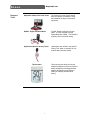
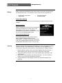
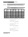
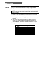
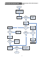
Revision Date: August 7, 2008 TABLE OF CONTENTS FORWARD I Introduction Revision Notice i i Alternator Ground Side Voltage Drop Test Charging System Load Test 17 18 SAFETY General Safety Instructions i ii STARTING SYSTEMS 19 Required Tools 1 BATTERIES 2 Starting Systems in Turf Equipment Inertia Drive Starters Conventional Starters 19 19 19 Gear Reduction Starters Problems Suggested Preventative Maintenance 19 20 20 Starter Motor Feed Side (High Amp) Circuit Voltage Drop Test 21 Ratings Capacity Identification 2 2 3 Types Inspection and Analysis Common Issues 4 4 5 Test Basics Specific Gravity Test Open Circuit Voltage Test 7 7 7 Load Test Battery Charging / Activation Basics Slow Battery Charging 8 9 9 Fast Battery Charging Dry Battery Activation Storage Guidelines 9 10 11 How to Jump Start a Battery Battery Removal Battery Installation 12 12 12 CHARGING SYSTEMS 13 Charging Systems in Turf Equipment Generators Alternators 13 13 13 Problems Suggested Preventative Maintenance Test Basics 14 15 16 Charging System Output Voltage Drop Test – Basics Alternator Feed Side Voltage Drop Test 16 17 17 Starter Solenoid Energize Circuit (Low Amp) Voltage Drop Test Method 21 Solenoid Energize Circuit (Low Amp) Test Method Starter Draw Test 22 23 TROUBLESHOOTING 24 Overview Testing Notes & Tips Current Drain Test Current Draw Diagnosis 24 24 25 25 ADDITIONAL MATERIALS BOOKMARK NOT DEFINED. © 2008 The Toro Company. All Rights Reserved. ERROR! FORWARD Forward Introduction This book aims to provide an easily accessed guide to the operation and diagnosis of various electrical starting/charging systems in Toro Commercial products. Inside you will find: ▪ ▪ ▪ ▪ Testing Procedures Typical Supply System Issues Battery Charging/Activation Procedures Troubleshooting Trees Technicians using this reference may find it easier to diagnose common issues with electrical supply systems on Toro Commercial Products. Please note, however, that reading this guide is not a substitute for product specific Operator & Service manuals. General knowledge and electrical proficiency are also assumed. NOTE: This guide does not contain information on the charging/maintenance of Deep Cycle Batteries. Deep Cycle Battery information and testing will be included in future revisions to this document. Revision Notice This guide will be edited on an as-needed basis to keep it current with standard tests, applicable battery types, and advances in the field as technology on Toro equipment continues to evolve. SAFETY READ THIS SECTION before performing any of the tests or checks listed in this guide. Electrolyte is composed of roughly 38% sulfuric acid; it is dangerous to work with if proper safety precautions are not observed. Follow the directions listed below if electrolyte comes in contact with either the skin, eye(s), or vehicle surface: ▪ ▪ ▪ Skin: Immediately flush the affected area with cold water. Eye(s): Immediately flush the affected area with cold water and call a doctor. Vehicle Surface: Flush the affected area with cold water, then apply a mixture of baking soda and cold water to neutralize the acid. Mandatory Precautions: ▪ ▪ ▪ ▪ ▪ ▪ ▪ ▪ NEVER smoke or allow open flame near batteries. Always wear eye protection when working around batteries. Never charge a frozen battery. Do not open maintenance free battery covers. Remove all jewelry and watches before performing service. Never lay tools on the battery. Always disconnect the negative cable first. Connect the negative cable last. i FORWARD General Safety Instructions Toro products are tested and certified for compliance with existing safety standards and specifications. Although hazard control and accident prevention partially are dependent upon the design and configuration of the machine, these factors are also dependent upon the awareness, concern and proper training of the personnel involved in the operation, transport, maintenance and storage of the machine. Improper use or maintenance of the machine can result in injury or death. To reduce the potential for injury or death, comply with the following safety instructions. ii TOOLS Required Tools Required Tools Adjustable Carbon Pile Load Tester The Carbon Pile Load Tester should have the capacity to handle the CCArated batteries on larger Commercial equipment. DVOM – Digital Volt Ohm Meter “DVOM” stands for Digital Volt Ohm meter. It is also referred to as the Digital Multimeter “DMM.” The DVOM is regularly used in electrical testing. Hydrometer/Specific Gravity Tester Hydrometers are utilized in the Specific Gravity Test, which is requisite for nonsealed battery warranty claims. Thermometers are utilized to test the ambient temperature of the environment where testing/work is being performed. Ambient temperature may affect the validity of readings obtained while testing. Thermometer 1 BATTERIES Ratings/Capacity Batteries Ratings Battery ratings are determined by how much current it can produce and how long it can sustain that current. The production rate of current can vary depending on: ▪ ▪ ▪ ▪ Surface area of the plates Temperature Electrolyte Strength Current Demand Ampere Hour Capacity This rating describes how much current the battery can supply for 20 hours if fully charged. Reserve Capacity Reserve capacity refers to the time (in minutes) that the battery will provide 25 A at 25˚C (80˚ F) to a final voltage of 1.75 V per cell. This rating estimates how long a battery could effectively power the vehicle if the charging system failed. Cold Cranking Amps (CCA) Cold Cranking Amps is a rating used to define a battery’s ability to start the product in cold temperatures. The rating is set by how many amps a new, fully charged battery can deliver at 0˚F for 30 seconds while maintaining at least 1.20 U per cell. Capacity The more electrolyte and electrode material there is in a cell, the greater its capacity. Capacity, however, is not a static rating. Performance will vary depending on circumstance. Review the points below for more information on capacity variance. 1. Batteries deliver less than 100% of their rated capacity when they are new. It takes multiple cycles before the acid works into the pores of the plates. 2. They also will deliver less than 100% of their capacity when operating in cold environments. 3. Battery life is closely related to the depth of discharge. The more capacity is used per cycle, the shorter the battery’s life will be. 4. Proper maintenance and charging is required for maximum capacity to be achieved. 2 BATTERIES Identification Identification Toro uses different batteries to meet the needs of each product. This book references many different types, as listed below. To determine which battery is in the unit, check the part number on the battery or General Technical Service Bulletin (TSB) #06-01. BCI1 GROUPINGS 1 2 BY STARTING BATTERIES TORO PART NUMBER AND BATTERY CAPACITY Toro P/N BCI Group No. CCA2 @ 0˚F Reserve Minutes @ 25 Amps Post Type Wet/Dry Layout 99-7421 U1 300 28 L-type Wet Fig. 3 104-8162 U1 300 28 L-type Dry Fig. 3 104-0496 55 585 95 Tapered Wet Fig. 2 104-9979 55 585 95 Tapered Dry Fig. 2 106-5186 26 525 80 Tapered Wet Fig. 1 106-5187 26 525 80 Tapered Dry Fig. 1 108-1260 28 535 110 3/8 - 16 SS Dry Fig. 3 106-5186 34 690 100 Tapered Wet Fig. 1 106-5190 24 660 110 Tapered Dry Fig. 1 BCI: Battery Council International CCA: Cold Cranking Amps 3 BATTERIES Types Inspection and Analysis The definitions below are intended to highlight key differences between batteries, both supplied and aftermarket. Standard Starting These batteries are specifically developed for service on products with voltage controlled electrical systems. Types of Starting Batteries Inspection and Analysis Sealed (Low Maintenance/ Maintenance Free) • GEL • AGM A sealed battery is made with vent caps that cannot be removed. Water is not added to these batteries; therefore, the only service options available are thorough cleaning and recharging. Non-sealed • Wet • Dry Charged Non-sealed batteries allow for the addition of water to electrolyte to compensate for water loss during service. 1. Check the battery case for cracks and for loose or damage terminals. If either of these conditions exists, electrolyte leakage could occur and battery replacement would be required. 2. Check for damaged cables and connectors. Damaged insulation could expose bare wires and cause short circuit conditions. 3. Check for corrosion on terminals and acid or debris on top of the battery. Clean the terminals and case with a mixture of baking soda and water or commercial battery cleaners. Corroded terminals and dirty battery cases can cause a variety of problems such as self discharging, incorrect test readings and poor performance. 4. Check for loose terminal connections and loose hold-downs. Tighten as necessary. 5. Check the electrolyte level in non-sealed batteries. The level can be checked by viewing through the translucent plastic case or by removing the vent caps. If the electrolyte is low, add distilled water as required and charge (re-charge) the battery to ensure the water and acid mix. Avoid overfilling (see Troubleshooting, “Electrolyte Level (Non-sealed) Check”). 6. Record any aftermarket or non-standard electrical loads added to the equipment. 7. Record ambient temperature. 8. Work with customer to determine battery service requirements and understand any special operating considerations he or she may have. 4 BATTERIES Common Issues Sulfates Common Issues The process of discharging creates lead sulfate formation in both positive and negative materials (this is a normal chemical reaction reversed by charging). This buildup of lead sulfate is accelerated if a battery is operated at a low state of charge, such as 80% or less, allowing more sulfate buildup on the plates. Some reasons batteries operate at a low state of charge: ▪ ▪ ▪ Bad voltage regulators Loads that exceed alternator output Dirty/loose terminal connections The longer a sulfated battery is left the more likely it is to be irrecoverable. However, it is possible to reclaim some sulfated batteries through the correct recharging process. Corrosion Spilled electrolyte (or boiling over from improper activation procedures) and condensation from battery gassing may cause corrosion on terminals, connectors, etc. Corrosion increases electrical resistance, which diminishes charging efficiency and cuts down available voltage. It is also possible for corrosion to develop a current leak path, which would allow for selfdischarging. The most efficient means of handling corrosion is to perform standard “cleaning” maintenance outlined in the product Operator’s manual. Parasitic Loads Parasitic loads are small currents (generally within a few mA) continuously delivered from the battery. In Toro Commercial products, any current drain above 50 mA demonstrates an excessive load. Any reading below 50mA is within normal operating condition. Self Discharging Self-discharging is often considered a condition of “parasitic load”; however it refers to the battery discharging slowly on its own over time due to buildup on its external surfaces. If the battery finds a direct path to ground, it will discharge itself as it sits – though no “load” has been placed on it. To prevent selfdischarging, ensure that all stored batteries are in a clean/dry place and checked regularly for charge. Electrolyte Level The level of electrolyte in the battery should be checked at least every 50 hours of operation. Failure to do so may result in decreased performance including lack of power and/or failure to start. Condition of Battery Cables Battery cables should be in good condition with clean/tight connections at both ends. There should be no cracks or bare spots on the cables (especially the positive cable). If there is more than a 0.2V drop across a connection it requires cleaning. After cleaning, use Battery Terminal Protector (Toro Part No. 107-0392) or petroleum jelly to help prolong battery life and reduce corrosion. 5 BATTERIES Common Issues Vibration/Battery Mounting Turf care equipment is operated on bumpy terrain so battery mounting hardware should always be kept tight to secure the battery against shock and vibration which could cause internal damage or cracked cases. Overcharging Undercharging See Charging Systems. See Charging Systems. 6 BATTERIES Tests Test Basics The condition of the battery will determine much of its performance. Regular maintenance procedures vary by battery, but are outlined in product specific Operator and Service manuals. Specific Gravity Test State-of-charge can be measured by measuring specific gravity with a hydrometer. IMPORTANT: Make sure the area around the cell caps is clean before removing any of the caps. 1. Crank the engine for about 3 seconds to remove the battery surface charge. 2. Remove all fill caps on the battery. 3. If electrolyte is low, follow “Electrolyte Level Non-Sealed Battery Flowchart” in this guide. 4. Allow the battery to stabilize for 15 minutes after charging since specific gravity readings obtained just after charging will not be accurate. 5. Hold the hydrometer vertically while positioning the hose in the battery cell. 6. Squeeze, then release the hydrometer bulb to draw in electrolyte, then spray the electrolyte back into the cell. Repeat until the float temperature matches the temperature of the electrolyte in the cell. Record readings for each cell on worksheet (see Additional Materials, page x). Open Circuit Voltage Test The Open-Circuit Voltage Test (no load on the battery) is performed with a voltmeter. The battery cables must be disconnected for this test. 1. Remove the negative cable first, and then the positive cable. 2. If the battery has recently been charged, boosted, or load tested, allow it to stabilize for 15 minutes before starting the test. 3. Connect the voltmeter leads to the battery terminals. Make sure the positive meter lead is connected to the positive battery terminal and the negative meter lead is connected to the negative battery terminal. 4. Record voltage on worksheet (see Additional Materials, “Worksheet”). 7 BATTERIES Load Test Tests Open-circuit voltage readings provide a general indication of battery condition. Battery condition can be checked more accurately by performing an electrical Load Test. NOTE: To prevent sparking, make sure the electrical load tester is turned off while connecting leads to the battery. Some load testers will also require a voltmeter be attached to the battery. 1. Perform an Open Circuit Voltage Test prior to performing the Electrical Load Test. If the voltage is less than 12.4V, recharge the battery. 2. Connect the load tester. 3. If the battery was charged, crank the engine for 3 seconds or use the tester to apply a 50 amp load for 3 seconds. This should reduce the surface charge of the battery. 4. Apply the “test load” (usually 1/2 of the rated Cold Cranking Amps) for 15 seconds while monitoring the battery voltage. Record on worksheet (see Additional Materials, “Worksheet”) the voltage at 15 seconds with the load on and immediately shut the load off. 5. Using the table below, determine the minimum voltage at the current cell temperature reading. Minimum Voltage 9.6 9.5 9.4 9.3 9.1 8.9 8.7 8.5 Battery Electrolyte Temperature 70˚F (and up) 60˚F 50˚F 40˚F 30˚F 20˚F 10˚F 0˚F 8 21.1˚C (and up) 15.6˚C 10.0˚C 4.4˚C -1.1˚C -6.7˚C -12.2˚C -17.8˚C BATTERIES Charging/Activation Battery Charging / Activation Basics Some of the most common failures of batteries are caused by improper activation/charging procedures. Listed below are many of the main charging/activation procedures for Toro Commercial products. Slow Battery Charging Slow charging is the ideal charging method, as it allows battery cells to equalize, thus reducing the risk of gassing and overcharging. 1. Inspect the battery as outlined on page 5 under “Inspection and Analysis”. 2. If the battery is in the vehicle, disconnect the battery cables to protect electronic devices. 3. Make sure the charger is turned OFF prior to connecting to the battery. 4. Attach the positive charger lead to the positive battery post. 5. Attach the negative charger lead to the negative battery post. 6. Set the charger to the correct voltage and appropriate amperage outputs (this should be the lowest possible amperage setting to recharge the battery in the time available – refer to chart above). 7. Turn on the charger. 8. Leave the battery on the charger until it is fully charged (12.4V/1.225 SG). NOTE: If violent gassing or spewing of electrolyte occurs, or the battery feels ‘hot’ to the touch (125°F or 51.7°C), stop charging the battery IMMEDIATELY. Fast Battery Charging Fast charging sends a high current through the battery to charge it quickly. 1. Inspect the battery as outlined on page 5 under “Inspection and Analysis”. 2. If the battery is in the vehicle, disconnect the battery cables to protect electronic devices. 3. Turn the charger OFF prior to connecting to the battery. 4. Attach the fast-charger positive lead to the battery positive post. 5. Attach the fast-charger negative lead to the battery negative post. 6. Set the charger to the correct voltage and appropriate amperage outputs. 7. Turn on the charger. 8. Watch battery temperature. If it reaches 125˚F (51.7˚C), lower the rate of charge immediately. 9. Test Battery Charge (using Specific Gravity or Open Circuit Voltage Test) after one hour. a. If an increase in Voltage is not visible, it will be necessary to slow charge the battery. b. If increase in Voltage is visible, continue charging until fully charged (12.4V/1.225 SG). NOTE: If violent gassing or spewing of electrolyte occurs, or the battery feels ‘hot’ to the touch (125°F or 51.7°C), stop charging the battery IMMEDIATELY. 9 BATTERIES Dry Battery Activation Charging/Activation Failure to appropriately activate dry-charged batteries is the leading cause of failures (dead batteries, shortened life spans, etc.) for the battery type. Follow the activation procedures listed below to ensure expected battery life. WARNING: Electrolyte contains sulfuric acid which is harmful to skin, eyes, and clothing. Wear eye protection and rubber gloves. If spillage occurs on body or clothing, rinse at once with water for at least 15 minutes. Rinse empty electrolyte package with large quantities of water. DESTROY EMPTY PACKAGE IN COMPLIANCE WITH LOCAL REGULATIONS TO PREVENT ACCIDENTS. After the battery has been activated, add only distilled water to replace normal loss. CAUTION: ALWAYS WEAR EYE PROTECTION! Use only battery electrolyte (1.265 SG) to fill the Battery before installing in the vehicle. Automotive Batteries (Group 55, Group 26, Group 24) 1. Remove vent plugs. 2. Fill each cell until electrolyte level rises to split ring at the bottom of the vent well (battery and acid must be at a temperature of 60˚F to 100˚F (15.5˚C to 38˚C) at time of filling. DO NOT OVER FILL. 3. After filling cells, wait five to ten minutes and additional electrolyte if necessary to bring electrolyte to proper level. DO NOT OVERFILL. 4. Replace vent caps before charging. 5. Charge battery at 25-30 amps (typically for 10 to 15 minutes) or at 4-6 amps (typically for 30 minutes) until SG is 1.225 and the electrolyte temperature is at least 60˚F (15.5˚C). BOTH CONDITIONS MUST BE MET. 6. After charging, check electrolyte levels. If required, add additional electrolyte to bring all levels to the bottom of the vent wells. DO NOT OVERFILL. NOTE: If the battery requires topping-off while in service, add distilled water. DO NOT ADD ACID. U1 Batteries 1. Remove slotted screw-in plugs. 2. Fill each cell until electrolyte level rises to split ring at the bottom of the vent well (battery and acid must be at a temperature of 60˚F to 100˚F (15.5˚C to 38˚C) at time of filling. DO NOT OVER FILL. 3. After filling cells, wait five to ten minutes and additional electrolyte if necessary to bring electrolyte to proper level. DO NOT OVERFILL. 4. Replace slotted screw-in plugs before charging. 5. Charge battery at 25-30 amps (typically for 15 to 20 minutes) or at 4-6 amps (typically for 120 minutes) until SG is 1.225 and the electrolyte temperature is at least 60˚F (15.5˚C). BOTH CONDITIONS MUST BE MET. 6. After charging, check electrolyte levels. If required, add additional electrolyte to bring all levels to the bottom of the split ring of the vent well. DO NOT OVERFILL. NOTE: If the battery requires topping-off while in service, add distilled water. DO NOT ADD ACID. 10 BATTERIES Storage Guidelines Storage Guidelines Battery life can be greatly increased by following the correct storage procedures. Before storing the battery: ▪ ▪ ▪ ▪ ▪ Clean the battery case and terminals with baking soda and water. Disconnect or remove the battery cables from the battery (leave disconnected). Check the electrolyte level and add distilled water if needed. Test battery to make sure it is fully charged. Charge battery. Batteries stored in a discharged state may suffer from one or more of the following. Freezing • Fully Charged Batteries don’t freeze unless the temperature reaches approximately -30˚F (-34˚C). • If discharged, a battery can freeze at 32˚F(0˚C). Sulfation Increased rate of discharge Wet/Dry Battery Storage Requirements (Prior to Installation): ▪ ▪ ▪ ▪ ▪ Dry Cool (not below 32˚F or 0˚C). Well-ventilated. Up-right DO NOT STACK WET BATTERIES ON TOP OF ONE ANOTHER unless in cartons. If in cartons, do not stack more than three high (or two for Heavy Duty Commercial). “During Storage” Required Maintenance: ▪ ▪ ▪ Rotate stock. Shelf life ranges from twelve to eighteen months, depending on environment and maintenance. WET ONLY: Test every four to six months and recharge if necessary. Always test prior to installing in equipment. DRY ONLY: Dry-charged batteries have a shelf-life of four to four-and-a-half years when stored at a constant temperature. It is wise to activate them before the third year of storage to ensure expected life. 11 BATTERIES How to Jump Start a Battery Installation Safety glasses must be worn when performing work on all products. Never lean directly over battery when testing, jump starting, or performing other maintenance. Be sure vent caps are tight and level. Be sure vehicles do not touch each other. 1. Connect one end of positive (+) booster cable to positive (+) terminal of discharged battery, wired to starter or solenoid. 2. Connect other end of positive (+) booster cable to positive (+) terminal of assisting battery. 3. Connect one end of negative (-) booster cable to negative (-) terminal of assisting battery, wired to ground. 4. Complete hook-up by connecting other end of negative (-) booster cable to the engine block or frame of the stalled product – as far away from the battery as possible and AWAY FROM MOVING FAN AND FUEL LINES. 5. Start the ‘jump’ vehicle and allow the engine to stabilize. 6. Start the ‘stalled’ vehicle. 7. Remove the jumper cables in the reverse order of connection (the negative (-) booster cable first, followed by the positive (+) booster cable. Battery Removal 1. Use proper safety equipment such as safety glasses and gloves. 2. Remove the negative battery cable first ▪ NOTE: Sometimes terminal fasteners may be difficult to loosen/move. In these cases use a battery terminal puller. Do not apply excessive force in an attempt to loosen the terminals as this may damage the battery posts 3. Remove the positive battery cable. 4. Remove the hold-down plate. 5. Take the battery out of the unit by using an approved tool/method (i.e., battery lift strap). It is important to make sure that the lift strap is secured before attempting any removal of the battery. Battery Installation 1. Before installing a battery (whether new or used), check the battery hold-down plate for corrosion. Should corrosion exist, clean it out with a solution of baking soda and water. Replace the battery hold-down plate if it is badly corroded. 2. The battery posts and cable ends should also be thoroughly cleaned with a solution of baking soda and water or battery cleaner. If a battery cable is cannot be serviced (if it is worn, insulation is peeling, or damaged in any way), replace the entire cable. 3. Position the battery in the machine so that the terminals are aligned appropriately with their cables. 4. Install the hold-down. DO NOT over torque the fasteners as this may distort the battery case. 5. Install the positive battery cable first, followed by the negative battery cable, and apply Battery Terminal Protector (such as Toro Part No. 107-0392). 12 CHARGING SYSTEMS Basics/Generators/Alternators Charging Systems Charging Systems in Turf Equipment Turf equipment may have a battery starting system, battery ignition, and accessories (such as lights, electric clutches, electric valves and electronic controls). With all the demands placed on the battery, some provision must be made to recharge the battery or the battery would soon become discharged. NOTE: Demand, created by powered accessories, may exceed the available capacity of the charging system. For example, non-standard cabs on larger equipment (with lights, A/C, etc.) often demand more than the charging systems were designed to handle. Generators Generators are commonly known as “dynamos”. As elements within the generator spin, electricity is produced. As the armature is spun by the rotation of the belt and pulley, current and voltage are generated. Generated current and voltage are directly proportional to the speed of the armature and the strength of the magnetic field. Figure 1 - Generator Alternators Alternator systems produce alternating current (AC) within the alternator and then convert this AC current into DC current. This charges the battery and then powers the rest of the electrical system. 13 CHARGING SYSTEMS Problems Undercharging / No Charge These are the most common charging system problems. Low or no charging causes slow cranking speed, failure to crank, and dim headlights (for those units equipped with light kits). If the unit has an ammeter, it will indicate a low charging rate of 12V or less. The indicator light (when used) may be on or flicker when the engine/motor is running. Usual causes of undercharging are: ▪ ▪ ▪ Overcharging ▪ A defective voltage regulator is almost always the cause of overcharging. On very rare occasions, disconnected or highresistance regulator wiring causes this problem. A light whining noise from the alternator is normal. A loud whine at idle speed can indicate a faulty diode or stator. ▪ ▪ ▪ ▪ Indicator Light Issues a slipping/missing drive belt, a defect in the alternator/regulator, or high resistance in one or more of the charging system wires. Excessively bright lights and frequent bulb replacement indicate that the system is overcharging. If the vehicle uses an ammeter, it will indicate a high charging rate with a charged battery. ▪ Noisy Alternator Problems/Preventative Maintenance ▪ ▪ ▪ ▪ Diode and stator defects can also cause noise in the AM band of the radio. A loose or glazed belt can cause belt squeal. Dry or worn bearings can cause roaring or squealing noises. A loose pulley can cause clicking or rattling noises. If the ammeter needle does not move in either direction when the engine is started and operated, the ammeter is defective. If the charge indicator does not light when the key is on, the bulb is burned out or the regulator is disconnected or defective. If the light is on at any time the engine is running: the regulator may be defective, alternator connections may be loose, or idle speed may be too low. If the light is on when the key is off, the unit’s wiring has shorted. 14 CHARGING SYSTEMS Suggested Preventative Maintenance Problems/Preventative Maintenance Clean Alternator & Connection Points All alternator surfaces must be kept clean of dirt buildup, dust, and/or grease. Air flow passages should be inspected closely and cleaned – to ensure that air may easily pass through the unit. All connection points must be clean and clear of corrosion. Component Mounting Brackets Make sure that charging system components are securely mounted to brackets; the brackets should also be checked to ensure that they are bolted securely. If charging system components are poorly/ loosely mounted, damaging vibration and diminished belt drive performance may result. Tension & Condition of Belts DO NOT perform this maintenance with the engine on. Check the belt for proper tension (see product specific operator’s manual). Adjust belt if improperly tensioned, as it may fail to turn the alternator’s rotor. Inspect it for glazing, cracks, or dryness. A worn or damaged belt should be replaced. 15 CHARGING SYSTEMS Test Basics This section outlines three crucial tests for the supply system: ▪ ▪ ▪ Charging System Output Tests Charging System Output Charging System Load Voltage Drop This is a simple test used to determine if a charging system is functioning. It will tell you if the charging system has an output, but not its capacity. • • Use a digital multimeter set to DC volts. Connect the positive (+) multimeter lead to the positive battery post and the negative (–) multimeter lead to the negative battery post. Keep the test leads connected to the battery posts and record the battery voltage. Record battery voltage on worksheet at back. Start the engine. Run at High Idle speed. Allow the battery to charge for at least 3 minutes. In most cases, the battery voltage will range from 13.5 volts to 14.7 volts. Record the battery voltage on worksheet (see Additional Materials, “Worksheet”). IMPORTANT: Upon starting the engine, the battery voltage will drop and then should increase once the engine is running. Depending upon the condition of the battery charge and battery temperature, the battery voltage will increase at different rates as the battery charges. 16 CHARGING SYSTEMS Voltage Drop Test – Basics Tests The Voltage Drop Test is one of the most efficient methods of checking the resistance within an electrical circuit. The circuit can be tested by simply monitoring the consumed voltage (voltage drop) from one point to another. Another important factor is that it allows a technician to perform the testing without disrupting the circuit. This is especially useful when diagnosing intermittent electrical faults. Important testing notes: ▪ ▪ ▪ ▪ ▪ ▪ ▪ Normal safety precautions apply: Use test leads with built-in clamps and avoid placing test leads near moving engine parts. For accurate testing, the battery must have at least a 75% charge. Perform a Battery Inspection and Open Circuit Voltage Test as previously described in “Batteries - Tests”. All starter circuit voltage drop tests will require voltage measurement with engine cranking. Disable the engine so that it will not start while cranking and limit cranking time to 15 seconds or less. All charging system tests are performed with the engine running. Ensure test points are clean and provide good continuity. Always refer to the specific operator and service manuals when performing electrical circuit testing. Alternator Feed Side Voltage Drop Test 1. Connect the DVOM positive lead to the alternator output (b+) terminal. 2. Connect the DVOM negative lead to the positive (+) battery post. 3. With engine running at high idle speed with all lights and accessories on, check the voltage drop reading. It should be 0.2V or less. a. If the drop is excessive, inspect for clean, tight connections. b. If the connections are good, inspect for damaged, corroded or undersized cables. Alternator Ground Side Voltage Drop Test 1. Connect the DVOM negative (-) lead to alternator case. 2. Connect the DVOM positive (+) lead to battery negative (-) post. 3. With engine running at high idle speed with all lights and accessories on, check the voltage drop reading. a. If the drop is excessive, inspect for clean, tight connections. b. If the connections are good, the negative cable most likely needs to be replaced. Note: Some alternators are mounted in rubber bushings and have a separate ground circuit. If so equipped, be sure to check the voltage drop across this circuit as well. 17 CHARGING SYSTEMS Charging System Load Test Tests To test the charging system current and voltage output capabilities, perform a Charging System Load Test. This test will determine if the current and voltage output meet the specification of the alternator being tested. If the specifications cannot be met, the alternator or regulator may need to be replaced. This test is performed by applying a variable load to the battery and measuring the charging system current. 1. Connect special load testers per manufacturer’s instructions (i.e. VAT 40). If a special load tester is not available, connect the load leads (carbon pile) and voltmeter leads to the battery terminals. Connect an ammeter clamp-on pickup around the battery ground (-) cable. If there is more than one cable, ensure the clamp is connected around all cables. 2. Ensure all meters are properly zeroed before testing. 3. Start the engine and run at high idle as stated in the service manual. 4. After running the engine for at least 3 minutes, read the ammeter and voltmeter readings. The ammeter reading indicates the base current required to power the ignition system and accessories before it can provide current to charge the battery. Document the ammeter reading. a. The total current should be less than 10 amps. If the reading is above 10 amps, the battery may still be charging. Continue testing once the battery is fully charged. b. The voltage reading should typically be between 13.5 to 14.7 volts. If the voltage values are not in this range, perform circuit inspections and refer to the appropriate service manual for overcharging or undercharging. 5. With the engine still running at high idle RPM, adjust the load increase control to obtain the highest ammeter reading possible without allowing the voltage to drop below 12 volts. 6. Monitor the ammeter reading during the load process and document. 7. Add the base reading from step 4 to the load reading in step 5. The total current should be within 10% of the alternator’s rating. Refer to the service manual for specific alternator testing if the output rating cannot be obtained. 18 STARTING SYSTEMS Basics Starting Systems Starting Systems in Turf Equipment Toro’s commercial turf products are equipped with a variety of engines ranging from one cylinder, air-cooled, gasoline engines to four cylinder, liquid cooled, diesel engines. Most of these engines use an electric starting system to crank and start the engine. The starter motor converts electricity, provided by the battery, into mechanical or rotating energy to turn the engine. This mechanical energy turns the engine at 200 – 250 RPM, allowing the engine to start. Inertia Drive Starters Inertia drive starters are very simple and consist of a motor assembly and pinion drive gear. When power is applied to the motor, the armature rotates and the drive pinion moves out and meshes with the flywheel ring gear. When the pinion reaches the end of the drive shaft, it rotates the flywheel and “cranks” the engine. The pinion drive gear also has a one-way clutch to avoid damage once the engine starts and overruns the starter motor shaft rotation speed. Conventional Starters Many gasoline engines have conventional starter motors. These motors consist of a motor assembly, control solenoid, pinion drive gear and overrunning clutch. When the starter is engaged, the pinion gear will turn at the same speed as the motor armature or shaft. Typical cranking power ranges from 0.8 Kw to 1.0 Kw. Gear Reduction Starters Diesel engines use gear reduction starter motors. These motors consist of a motor assembly, control solenoid, pinion drive with overrunning clutch and reduction gears. The gear reduction allows the starter to be compact, lightweight and at the same time, provide increased torque to crank the higher compression diesel engine. The torque reduction will typically reduce the pinion drive speed 1/3 to 1/4 the armature speed; however it will still turn faster than the conventional starter. Typical cranking power ranges from 1.0 Kw to 2.2 Kw. 19 STARTING SYSTEMS Problems Engine Will Not Crank Several factors could cause the engine not to crank when attempting to start. Most common problems are: ▪ ▪ ▪ ▪ ▪ ▪ Starter Turns Slowly a dead or weak battery, faulty or improperly adjusted safety interlock switches, blown fuses or fuse links, poor cable or wiring connections, internal engine damage or a faulty starter motor. A slow cranking starter could be caused by: ▪ ▪ ▪ ▪ Noisy Starter Problems/Suggested Maintenance a weak battery, poor cable or wiring connections, internal engine damage, or faulty starter motor. Starters can make a variety of noises. If the starter motor makes a clicking noise during start attempts: ▪ ▪ ▪ ▪ the battery could be weak, the motor could be faulty, or there could be poor connections, or faulty cables/wiring. A grinding noise is most likely the result of a damaged drive gear and engine flywheel. A drive gear that has not fully retracted after starting the engine could cause a whining noise. Starter Spins, But If the starter drive only spins, it may have a faulty drive (overWill Not Crank The running) clutch or the drive gear and flywheel ring gear may be damaged. Engine ▪ Inspect the flywheel. Replace as necessary. ▪ Inspect overrunning clutch. Replace as necessary. Suggested Preventative Maintenance The starter systems require very little maintenance. Since the starting system relies heavily on a strong battery, ensure the battery is properly charged and clean of corrosion. All cables and wiring should be tight and routed away from any moving parts. The starter motor should be mounted securely to the engine block to avoid damage to the starter motor and provide a good ground for the starting circuit. Do not crank the starter for extended periods of time. Avoid over running the starter during no start condition by limiting cranking time to 15 seconds or less. 20 STARTING SYSTEMS Tests Starter Motor Feed Side (High Amp) Circuit Voltage Drop Test 1. Check the entire motor circuit by connecting the DVOM positive lead to the battery positive post (+) and the DVOM negative lead to the starter terminal post. 2. Crank the engine while monitoring the voltage reading. A good high amperage circuit should have a voltage drop of 0.4 volts or less. 3. If the voltage drop exceeds 0.4 volts, test the circuit incrementally by working from the starter terminal to the positive battery terminal until the excessive drop is identified. Many times, the testing start point may depend on ease of access to test points or a suspected faulty component. Keep in mind that starter circuits will vary from model to model. Test readings exceeding 0.4 volts could be caused by a poor connection, damaged cable, corrosion or a defective relay. Voltage drop readings at the battery post to terminal should be zero volts. 4. Once the fault is identified, repair or replace the component(s), or clean connections as necessary and test again to verify the repair. Starter Solenoid Energize Circuit (Low Amp) Voltage Drop Test Method 1. Check the entire starter solenoid energize circuit by connecting the DVOM positive lead (+) to the battery positive post (+) and the DVOM negative lead (-) to the starter “S” terminal. 2. Ensure all safety interlocks are properly positioned to allow the engine to crank. Common interlocks include the neutral switch, PTO engagement switch, parking brake switch, and traction control. 3. Crank the engine while monitoring the voltage reading. A good circuit should have a voltage drop of 0.2 volts or less. If the battery cranking speed is slow or if the current draw is excessive, the starter motor is most likely defective. If the voltage drop exceeds 0.2 volts, the circuit resistance is high. 4. Check the interlock components for excessive voltage drop. Standard contact switches should not exceed 0.2 volts. Once the fault is identified, repair or replace the component(s), or clean connections as necessary and test again to verify the repair. 5. ***Another option is to keep the positive DVOM lead (+) connected to the terminal and move the DVOM negative lead (-) towards the battery until the point of high resistance is located. 21 STARTING SYSTEMS Solenoid Energize Circuit (Low Amp) Test Method Tests The Solenoid Energize Circuit (Low Amp) Test checks the low amperage signal from the ignition start circuit to the starter motor solenoid. Many factors can cause the loss of a start signal. In most cases a faulty safety interlock switch (such as a neutral, PTO, parking brake or joystick safety switch) is the causal factor. 1. Review and understand the starting circuit and required conditions to allow the signal to reach the starter solenoid. 2. Ensure all levers, switches and safety components are in the proper position for starting the engine. Refer to the appropriate operator’s manual for specific settings. 3. Remove the connector from the starter solenoid “S” terminal. 4. Connect the DVOM negative lead (-) to ground and the positive lead (+) to the starter solenoid signal wire connector. 5. Turn the ignition switch to start and monitor the voltage reading. 6. Voltage should be greater than 12V with a fully charged battery. ***See previous page, “Starter Solenoid Energize Circuit (Low Amp) Voltage Drop Test,” number 5. Note: If the unit uses an ECM or ECU, the ACE Handheld Diagnostic Display can be used to verify the output signal. Conduct output testing with the ACE Handheld Diagnostic Display as directed by the appropriate service manual. If there is no “start” output signal identified by the Diagnostic Display, refer to the service manual and wiring schematic for testing the appropriate inputs. Note: For units that use an ECM or ECU, performing this test may trigger a fault within the processor memory. Be sure to clear all faults and retest once repairs have been completed. 22 STARTING SYSTEMS Starter Draw Test Tests The Starter Draw Test provides an easy way to test the condition of the high amperage starting system by monitoring the starting system current draw and cranking voltage. This test will determine if the cranking current and voltage values are within reasonable specifications and the results can identify potential starter motor, starter circuit and even internal engine faults. This test is performed by monitoring the starter current draw and battery voltage while the engine is being cranked. Typical starter current draw for commercial three cylinder diesel engines is 150 – 200 amps and the cranking voltage should range from 9.6 to 11 volts during normal operating temperatures. 1. Ensure the battery is in good condition and properly charged. Refer to Battery Electrical Load Test. 2. Connect special load testers per manufacturer’s instructions (i.e. VAT 40). If a special load tester is not available, connect the voltmeter leads to the battery terminals. Connect a separate ammeter with clamp-on pickup around the battery ground (-) cable. If there is more than one cable, ensure the clamp is connected around all cables. 3. Ensure all meters are properly zeroed before testing. 4. Make sure all equipment accessories are turned off. 5. Disable the engine so that it does not start during the test procedure. 6. Crank the engine while observing the voltmeter and ammeter readings. a. Cranking voltage should be above 9.6 volts. b. Current draw should be between 150 – 200 amps. c. Engine cranking RPM should be 175 – 250 RPM. 7. Current draw above 200 amps usually indicates a faulty starter motor. Perform starter motor testing as outlined in the appropriate service manual as required. Also, keep in mind that excessive current draw could also be caused by internal engine damage. 8. Low current draw with excessive cranking voltage indicates high resistance in the starter circuit. Refer to Starter Motor Feed Side Voltage Drop Test for additional testing information. 23 TROUBLESHOOTING Basics Troubleshooting Overview This section provides a selection of tests/troubleshooting trees to address some of the most common problems with Electrical Supply Systems in Toro commercial products. 1. 2. 3. 4. 5. 6. 7. Testing Notes & Tips ▪ ▪ ▪ ▪ ▪ ▪ ▪ Current Drain Current Draw Non-sealed Battery Check Electrolyte Level (Non-sealed Battery) Check Maintenance Free Battery Check Nothing Happens When Start Attempt is Made Battery Goes Dead Normal safety precautions apply: Use test leads with built-in clamps and avoid placing test leads near moving engine parts. Don’t overlook the basics. Before performing any test in this section, perform a proper visual inspection of the affected system such as checking for loose connections, corroded terminals, proper belt tension, etc. It is important to understand circuit operation prior to testing. Always refer to the electrical schematics in product specific service/operator manuals. NOTE: The operator manuals will usually have the latest wiring and hydraulic schematics. Interlock testing is not addressed in this reference manual and must be tested with the specific procedures outlined in the appropriate service manual. When performing electrical tests, make every effort to retain circuit integrity by not disconnecting components or connectors. Systems with an Electronic Control Module (ECM) can introduce misleading trace voltage values when components such as solenoids are disconnected. Avoid piercing wiring insulation when performing tests. If left exposed, damaged insulation could eventually cause internal wire corrosion resulting in electrical malfunctions. When diagnosing intermittent faults, it is important to carefully perform testing while leaving suspect harnesses, wiring and connectors in their natural position. Abrupt or excessive movement of these components could temporarily remove the open or short circuit condition and prolong the diagnostic process. 24 TROUBLESHOOTING Current Drain Test Basics Current drain at the battery should not exceed 50 mA (.050 amp) when all electrical components are turned off and the unit is at rest. Current drain can be tested with the following procedure: NOTE: Using a test lamp or voltmeter is not an accurate method of determining current draw. An in-line digital ammeter, DVOM, or analog ammeter must be used. 1. Make sure fuses are accessible prior to performing test. 2. Disconnect the negative battery cable and install the ammeter in series between the negative battery post and negative cable end. The meter must be capable of reading milliamps and have at least a 10 amp capability. Current Draw Diagnosis 1. If the draw is above 50 mA, (.050 amp), remove fuses from the fuse block one at a time and note the current drop to identify the offending circuit. Do not reinstall the fuses until you are finished testing. 2. If the draw is still present after pulling all the fuses, check the wiring schematic in the operator’s manual for circuits that run from the battery without passing through the fuse block. Disconnect these circuits to identify the offending circuit. 3. The fuse that reduces the current draw is connected to the component that is causing the current drain. Refer to the electrical schematic in the Operator’s manual for details. 25 Nothing Happens When Start Attempt is Made TROUBLESHOOTING Start Follow “Maintenance Free Battery Check” or “Non-sealed Battery Check” flowchart Check to see if engine turns by hand. No Perform mechanical repairs on engine. ≥ 12 V No Starter SIGNAL circuit testing (outlined in Product Service Manual) Engine will not crank Yes Pass Engine Turns By Hand Yes Test for 12V at the Starter SIGNAL while cranking. Starter Draw Test Yes > 150-200 A Test/replace Starter Motor. Starter Circuit Voltage Drop Test Yes No Repair/replace required components. Voltage Drop ≤ 0.5 V No Repair or replace faulty circuit. Retest. Yes Check if problem still occurs. Symptom Repaired Repeat testing outlined above. Various environmental factors may have caused a false reading. No Yes Stop 26 TROUBLESHOOTING Battery Goes Dead Start Follow “Maintenance Free Battery Check” or “Non-sealed Battery Check” flowchart Charging System Output Test Increases by 0.5V or greater No Charging System Service – Refer to product Service Manual for more information on this repair. No Repair/replace components as necessary. Yes Current Drain Test ≤ 50 mA Current DrainTest (2nd time) No Yes ≥ 50 mA Yes Monitor battery performance in standard use. Symptom Repaired No Repeat testing outlined above; various environmental factors may have caused a false reading. NOTE: Operator induced faults such as keeping the ignition key in the run position or leaving the lights on can drain the battery. 27 TROUBLESHOOTING Non-sealed Battery Check Start Perform “Visual Inspection” Does Electrolyte need to be added? No Perform “Open Circuit Voltage Test” or “Specific Gravity Test” Is reading(s) below 12.4V/1.225 SG (or no greater difference of 0.050 between cells? Is Battery taking charge? (Open circuit voltage > 12.4V or SG > 1.225) Yes Yes Charge Battery. No No Perform Battery “Load Test” Does battery maintain a minimum Voltage? (See table in battery “Load Test” section) No Is this the second “Load Test” failure? Yes Yes Do not replace the Battery Replace the battery. Stop 28 Yes No Add distilled water. Reference “Electrolyte Level (Non-Sealed Battery) Check” flowchart TROUBLESHOOTING Electrolyte Level (Non-sealed) Check Start Check Electrolyte Level Add Distilled Water (bring levels to bottoms of the Split Ring of the Vent Well) Yes Does Electrolyte need to be topped off? No Is Electrolyte Level below the plates? No Yes Go to “Non-Sealed Battery Check” Flowchart Add Distilled Water (bring levels to bottoms of the Split Ring of the Vent Well) Charge the battery (through an external charger, or by running the product for a few hours) 29 TROUBLESHOOTING Maintenance Free Battery Check Start Perform “Visual Inspection” Perform “Open Circuit Voltage Test” Yes Is Battery taking charge? (Open circuit voltage > 12.4V) Is reading below 12.4V? Yes Charge Battery. No Perform Battery “Load Test” Does battery maintain a minimum Voltage? (See table in battery “Load Test” section) No Is this the second “Load Test” failure? No Yes Yes Do Not Replace Battery Replace the battery. Stop 30 No ADDITIONAL MATERIALS Electrical Starting/Charging Systems Worksheet Distributor Name: Technician/Technician Team: Customer Name: Contact Information: Ambient Temperature: BATTERY TESTS Specific Gravity Test Electrolyte Low? SG Reading for Each Cell Open Circuit Voltage Test Voltage Reading on 1st Test: Voltage Reading on 2nd Test: Load Test Voltage @ 15 Seconds with Load: CHARGING SYSTEM TESTS Output Test Starting Voltage: Battery Voltage after 3 min. on High Idle: Voltage Drop (Drop) Test Alternator Feed Side Drop: Alternator Ground Side Drop: Load Test Ammeter Reading @ High Idle: Ammeter Reading @ High Idle under Load: + Total Current = 31 Yes No 1 2 3 4 5 6 .