1
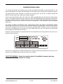
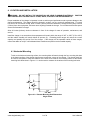
Legacy Platinum SCR Chargers
By Douglas Battery
Single-Phase SCR Battery Chargers
USER’S MANUAL
Important Safety,
Installation,
Operation, and
Maintenance
Instructions
www.douglasbattery.com
CHARGER RATINGS LABEL
The charger ratings label (see example below) provides the MODEL and SERIAL number identification for the
factory-configuration of the charger that was ordered. This information will be required if service parts are needed.
The factory-wired AC input information is provided on the rating label: AC VOLTS, AC AMPS, PHASE and
HERTZ. This information will be required for charger installation.
The DC output specifications, CELLS, DC VOLTS, DC AMPS, and AMP HRS, are the maximum nominal charger
ratings. The charger is capable of being configured for lower DC AMPS/AMP HRS and was factory-configured for
the output specified at the time of order, which means that the actual DC AMPS and AMP HRS output may be
configured to be lower than the maximums listed on the ratings label. TYPE indicates the factory-configured
battery type.
This charger is capable of multi-voltage output, multiple battery profiles, and capable of automatically charging
batteries with CELLS and DC VOLTS up to the maximums listed on the ratings label. Each CELLS/DC VOLTS
level requires configuration at the time of order to be active. Each CELLS/DC VOLTS level uses a unique battery
profile that is specified at the time of order, so the DC AMPS, AMP HRS, and TYPE listed on the ratings label
may not apply to all CELLS/DC VOLTS levels.
Please fill in the blank label that is provided below with the information from the ratings label on the front of your
charger for future reference.
Document any configuration or settings changes that are made by marking the ratings label on the front of your
charger or on an additional label or tag on the front of your charger.
SAVE THIS MANUAL: Keep it in a location where it is available to anyone who may
operate the charger.
www.douglasbattery.com
2 of 30
User’s Manual
TABLE OF CONTENTS
CHARGER RATINGS LABEL ...................................................................................................2 TABLE OF CONTENTS .............................................................................................................3 IMPORTANT SAFETY INSTRUCTIONS ...................................................................................4 1. INTRODUCTION ...................................................................................................................6 2. RECEIVING THE CHARGER ................................................................................................7 3. STORAGE .............................................................................................................................7 4. LOCATION AND INSTALLATION ........................................................................................8 4.1 Horizontal Mounting .................................................................................................................................................. 8 4.2 Wall Mounting (Optional) .......................................................................................................................................... 9 5. AC INPUT............................................................................................................................ 11 5.1 AC Voltage Connections......................................................................................................................................... 12 5.2 AC Voltage Jumper Positions ................................................................................................................................ 12 5.3 AC Fuses .................................................................................................................................................................. 12 5.4 Initial AC Power Up ................................................................................................................................................. 12 6. DOOR WITH SWITCHES AND AC CONTACTOR (OPTIONAL) ....................................... 13 7. DC OUTPUT ........................................................................................................................ 13 8. PROPER CARE OF DEEP-CYCLE MOTIVE POWER BATTERIES .................................. 13 8.1 Personal Safety Precautions .................................................................................................................................. 14 9. CHARGER OPERATION .................................................................................................... 15 9.1 Multi-Voltage Charging ........................................................................................................................................... 16 9.2 User Interface .......................................................................................................................................................... 16 9.2.1 Control Panel ........................................................................................................................... 17
9.2.2 Main Display ............................................................................................................................ 18
9.3. LCD Display and Navigation Pad User Interface ................................................................................................. 18 9.3.1 View Status .............................................................................................................................. 20
9.3.2 View Settings ........................................................................................................................... 20
9.3.3 Change Settings ...................................................................................................................... 20
9.3.4 History ...................................................................................................................................... 21
9.3.5 System Info .............................................................................................................................. 22
9.3.6 Clock ........................................................................................................................................ 22 9.4 Fault Monitoring ...................................................................................................................................................... 22 9.5 Self Diagnostic ........................................................................................................................................................ 23 9.6 System Settings ...................................................................................................................................................... 24 9.7 Battery Profile Settings ........................................................................................................................................... 27 10. MAINTENANCE ................................................................................................................ 28 10.1 Check Charger Area .............................................................................................................................................. 28 10.2 Visual Inspections ................................................................................................................................................. 29 10.3 Battery Conditions ................................................................................................................................................ 29 11. TROUBLESHOOTING AND SERVICE ............................................................................. 29 www.douglasbattery.com
3 of 30
User’s Manual
IMPORTANT SAFETY INSTRUCTIONS
1.
SAVE THESE INSTRUCTIONS – This manual contains important safety and operating instructions.
2.
Before using battery charger, read all instructions and cautionary markings on battery charger,
battery, and product using battery.
LOOK FOR THIS SYMBOL TO POINT OUT SAFETY PRECAUTIONS.
IT MEANS: BE ALERT—YOUR SAFETY IS INVOLVED. IF YOU DO
NOT FOLLOW THESE SAFETY INSTRUCTIONS, INJURY OR
PROPERTY DAMAGE CAN OCCUR.
3.
4.
DANGER: TO REDUCE THE RISK OF FIRE OR ELECTRIC SHOCK, CAREFULLY READ AND
FOLLOW THESE IMPORTANT SAFETY AND OPERATING INSTRUCTIONS BEFORE INSTALLING
OR OPERATING THE CHARGER.
INSTRUCTIONS IMPORTANTES CONCERNANT LA SECURITÉ.
5.
WARNING: TO REDUCE THE RISK OF FIRE, INSTALL THIS BATTERY CHARGER ON A
SURFACE OF NON-COMBUSTIBLE MATERIAL SUCH AS BRICK, CONCRETE, OR METAL.
6.
DANGER: RISK OF ELECTRIC SHOCK. DISCONNECT CHARGER FROM BATTERY AND AC
POWER BEFORE SERVICING. TURNING OFF THE CHARGER DOES NOT REDUCE THIS RISK.
7.
DANGER: RISK OF ELECTRIC SHOCK. DO NOT TOUCH UNINSULATED PORTION OF AC OR
DC CONNECTORS OR UNINSULATED BATTERY TERMINAL.
8.
DANGER: RISQUE DE CHOCKS ÉLECTRIQUES. NE PAS TOUCHER LES PARTIES NON
ISOLÉES DU CONNECTEUR DE SORTI OU LES BORNES NON ISOLÉES DE L’ACCUMULATEUR.
9.
CAUTION: CHARGE ONLY LEAD ACID BATTERIES. OTHER TYPES OF BATTERIES MAY
BURST CAUSING PERSONAL INJURY AND DAMAGE. BEFORE CHARGING ANY OTHER TYPE OF
RECHARGEABLE BATTERY, CHANGE THE CHARGER SETTINGS AS RECOMMENDED BY THAT
BATTERY MANUFACTURER.
10.
ATTENTION: UTILISER POUR CHARGER UNIQUEMENT LES ACCUMULATEURS AU PLOMB À
ELECTROLYTE LIQUIDE. D’AUTRES TYPES D’ACCUMULATEURS POURRAIENT ÉCLATER ET
CAUSER DES.
11.
CAUTION: DO NOT EXPOSE TO RAIN. INDOOR USE ONLY.
12.
ATTENTION: NE PAS EXPOSER À LA PLUIE.
13.
WARNING: DO NOT DISCONNECT THE CHARGER PLUG FROM THE BATTERY CONNECTOR
WHEN THE CHARGER IS ON. THE RESULTING ARCING AND BURNING WILL DAMAGE THE
CONNECTORS AND COULD CAUSE THE BATTERIES TO EXPLODE. TURN CHARGER OFF
FIRST!
www.douglasbattery.com
4 of 30
User’s Manual
14.
15.
DANGER:
TO PREVENT ELECTRICAL SHOCK, DO NOT TOUCH EITHER AC OR DC
UNINSULATED PARTS. MAKE SURE ALL ELECTRICAL CONNECTORS ARE IN GOOD WORKING
CONDITION. DO NOT USE CONNECTORS THAT ARE CRACKED, CORRODED OR DO NOT MAKE
ADEQUATE ELECTRICAL CONTACT. USE OF A DAMAGED OR DEFECTIVE CONNECTOR MAY
RESULT IN A RISK OF OVERHEATING OR ELECTRIC SHOCK.
WARNING: HAZARD OF ELECTRIC SHOCK.
16.
WARNING: Lead-acid batteries generate explosive gases. To prevent arcing or burning near
batteries, do not disconnect DC charging cord from batteries when the charger is operating. Push
and hold the “STOP/START” Button until charger turns OFF. Keep sparks, flame, and smoking
materials away from batteries.
17.
WARNING: Always shield eyes when working near batteries. Do not put wrenches or other
metal objects across battery terminal or battery top. Arcing or explosion of the battery can result.
18.
WARNING: Batteries produce hydrogen gas, which can explode if ignited. Never smoke, use
an open flame, or create sparks near the battery. Ventilate the area when the battery is charging
in an enclosed place.
19.
WARNING: Lead-acid batteries contain sulfuric acid, which may cause burns. Do not get acid
in eyes, on skin, or clothing. If contact with the eyes occurs, flush immediately with clean water
for 15 minutes and obtain medical attention.
20.
WARNING: Only your dealer’s Qualified Service Technicians should program or service this
equipment.
21.
CAUTION: Do not operate the charger if it has received a sharp blow, been dropped, or
otherwise damaged. Have your dealer’s Qualified Service Technician examine and repair as
needed.
22.
WARNING: Do not disassemble the charger. Have the charger examined by your dealer’s
Qualified Service Technician. Incorrect re-assembly of the charger may result in an explosion,
electric shock, or fire.
23.
CAUTION: Make sure the battery system has the properly rated voltage, amp-hours, and type
(Wet, Sealed, etc) for this charging system.
SAVE THESE INSTRUCTIONS
www.douglasbattery.com
5 of 30
User’s Manual
1. INTRODUCTION
This Legacy Platinum SCR battery charger is an advanced, silicon-controlled rectifier (SCR) charger. It was
factory-configured to charge wet/flooded or sealed deep-cycle lead-acid batteries. The charger has an “l-E-I”
profile, which is high-rate constant current (start/bulk region), constant voltage (plateau/absorption region), and
low-rate constant current (finish region). It is controlled by an advanced microprocessor controller.
Figure 1-1
lists the features of the controller, including automatic multi-voltage charging, individual amp-hour setting/battery
profile per DC voltage level, field programmability, and a real-time clock. The charger can also be configured for
opportunity charging.
Legacy Platinum SCR Controller Features
Advanced microprocessor control
User-specified, factory-configured battery profiles and AH settings
1-inch alphanumeric display characters
8 LED indicators and 4 buttons
Self diagnostic button
Voltage mismatch protection
Complete fault monitoring with shutdown protection
Automatic equalize/balance
Manual equalize/balance, stop, and start with buttons
Automatic multi-voltage charging
Individual battery profile and AH setting per voltage
2-line LCD display and navigation pad
“Plain English” menu system
Program/modify charger settings in the field
Review archived charge cycles
Real-time clock for time-of-day operations
Opportunity charging support
Figure 1-1: Legacy Platinum SCR Controller Features
www.douglasbattery.com
6 of 30
User’s Manual
Figure 1-2 provides specifications for the Legacy Platinum SCR product line.
Model
Number
AC
Phase
6-450B
6-550B
1
Nominal
DC Volts,
Max
12
1
6-680B
1
12-380B
12-550B
AC Amps
Cell Count,
Max
Amp-Hour Rating
(C5), Max (8 Hrs.)
DC Amps,
Max
208V
240V
480V
Approx Shipping
Weight (Lbs.)
6
450
72
10
9
4.5
180
12
6
550
88
12
11
5.5
190
12
6
680
109
14.5
13
6.5
193
1
24
12
380
61
16
14
7
200
1
24
12
550
88
22
19
9.5
223
12-680B
1
24
12
680
109
27
22
12
225
12-850B
1
24
12
850
136
33
29
14
260
18-600B
1
36
18
600
96
35
31
15
248
18-800B
1
36
18
800
128
45
38
19
290
24-600B
1
48
24
600
96
45.5
40
20
290
Figure 1-2: Legacy Platinum SCR Product Line Specifications
2. RECEIVING THE CHARGER
Unpack the charger and examine it for shipping damage. In the event that shipping damage is found, the
preferred course of action is for the recipient to refuse delivery from the freight company. After refusing delivery
of the charger, please contact your dealer to inform them of the refused delivery.
If the shipping damage is not discovered until after the item has been accepted from the freight company, please
report it as a claim to the carrier.
3. STORAGE
When the charger is stored prior to being installed and powered up, it must be stored indoors in a clean and dry
environment where the temperatures will remain within the range of 32ºF to 120ºF (0°C to 49°C). The charger
should be stored upright, bolted to the shipping pallet, and covered by the plastic wrap and shipping carton that it
was shipped in. This will help protect the charger from dust and abrasion. It should be stored in an area where it
is not likely to be damaged. Do not stack anything on top of the charger.
www.douglasbattery.com
7 of 30
User’s Manual
4. LOCATION AND INSTALLATION
WARNING: DO NOT INSTALL THE CHARGER ON OR NEAR FLAMMABLE MATERIALS. POSITION
THE CHARGER ON A FOUNDATION OF STONE, BRICK, CONCRETE OR GROUNDED METAL.
Proper installation of the charger is important in order to achieve good performance and to prevent damage to the
charger and batteries. The charger should be located in a clean, cool, dry, and well ventilated area. To permit
free air flow for convection cooling, allow 4 inches (102mm) minimum between the charger and any wall, 6 inches
(152mm) from other equipment, and never store anything beneath the charger. Do not obstruct the airflow space
around and beneath the charger.
Allow 36 inches (914mm) minimum clearance in front of the charger for ease of operation, maintenance, and
service.
Install the charger in an area where the temperatures will remain within the range of 32ºF to 105ºF (0°C to 40°C)
and the relative humidity will remain below 95 percent (%). Exceeding these ranges will reduce the current
capacity and possibly the service life of the charger. If the charger will be operated outside of these ranges,
contact the dealer to verify if it will withstand these conditions and perform at the needed capacity.
4.1 Horizontal Mounting
To bolt to the horizontal mounting surface, the mounting bolts will attach through the four mounting bolt slots
in the bottom surface of the charger legs that are nearest the corners of the charger. The charger itself can
be used as a template to mark the locations of the holes to be made in the mounting surface or the bottom
mounting hole dimensions in Figure 4.1-1 can be used to measure the locations of the mounting bolt holes.
Figure 4.1-1: Bottom Mounting Hole Dimensions
Single Phase
www.douglasbattery.com
8 of 30
User’s Manual
4.2 Wall Mounting (Optional)
WARNING: THE CHARGER IS NOT TO BE POSITIONED ON, OR MOUNTED OVER, ANY
FLAMMABLE SUBSTANCE.
WARNING: THE WALL AND THE FASTENERS USED MUST BE CAPABLE OF SUPPORTING THE
DESIGN LOAD SHOWN IN FIGURE 4.2-1. USE APPROPRIATE FASTENERS FOR THE WALL
CONSTRUCTION. THE USE OF FOUR MACHINE BOLTS IS REQUIRED TO SECURE THE LOAD.
NOTIFY YOUR DEALER’S QUALIFIED SERVICE TECHNICIAN IF YOU HAVE ANY QUESTIONS OR
PROBLEMS OCCUR.
CAUTION: ALLOW 4” (102mm) MINIMUM CLEARANCE BETWEEN THE CHARGER AND ANY
WALL, 6” (152mm) FROM OTHER EQUIPMENT TO ALLOW FOR PROPER VENTILATION.
CAUTION: TO ENSURE THE STRUCTURAL INTEGRITY OF THE WALL MOUNTING BRACKETS:
USE 8, 3/8’ DIAMETER BOLTS (NOT PROVIDED) TO ATTACH BRACKETS TO A WALL/STRUCTURE.
AVIOD USING LAG BOLTS.
To install the wall mounting brackets, this procedure must be followed in sequence. The brackets are to be
used as shown in Figure 4.2-2.
1. Locate the holes for the fasteners according to the dimensions in the illustrations.
applicable, connect fasteners directly to studs in the wall.
Note:
Where
2. Use a level to ensure proper mounting.
3. Use each bracket as a template and mark where the mounting holes should be located. When locating
the brackets, bracket flanges should face towards the inside. Do not use the slots for mounting the
bracket to the wall.
CAUTION: THE CHARGER MUST BE SUPPORTED UNTIL IT IS SECURED TO THE BRACKETS.
4. Secure charger to brackets using the hardware provided with the wall mounting kit.
appropriate illustration for placement instructions.)
(Refer to the
5. When the charger / wall brackets are mounted on the wall, there will be a clear airflow space at the rear of
the charger. This space should not be reduced or obstructed in any way.
WARNING: IF CHARGER IS DROPPED OR SEVERELY BUMPED DURING HANDLING, DO NOT
OPERATE CHARGER. POSSIBLE DAMAGE OR UNSAFE OPERATING CONDITIONS MAY OCCUR.
CONTACT YOUR DEALER’S QUALIFIED SERVICE TECHNICIAN.
www.douglasbattery.com
9 of 30
User’s Manual
Model Number
Enclosure Size
6-450B
6-550B
6-680B
12-380B
12-550B
12-680B
12-850B
18-600B
18-800B
24-600B
Single Phase
Single Phase
Single Phase
Single Phase
Single Phase
Single Phase
Single Phase
Single Phase
Single Phase
Single Phase
Charger Weight
lbs. (Kg.)
180 (82)
190 (86)
193 (88)
200 (91)
223 (101)
225 (102)
260 (118)
248 (113)
290 (132)
290 (132)
Design Load
lbs. (Kg.)
900 (410)
950 (430)
965 (440)
1000 (455)
1115 (505)
1125 (510)
1300 (590)
1240 (565)
1450 (660)
1450 (660)
WARNING:
DO NOT STACK CHARGERS WHEN USING WALL MOUNTING
BRACKETS. BRACKETS ARE DESIGNED TO SUPPORT ONE CHARGER ONLY.
Single-Phase Cabinet Dimensions: 19.0” W x 27.0” H x 17.5” D
Figure 4.2-1: Wall Anchor Design Load Table
Figure 4.2-1 shows the weight that the set of mounting bolts and their anchoring structure must
withstand for the various charger types. The “Design Load” shows the “Charger Weight” times a
safety factor of five (5). Be certain that both the mounting structure and the bolts will, at a
minimum, support the “Design Load”. Drywall or plaster will not be strong enough on its own,
without proper structural reinforcement.
Wall Fasteners
(Not supplied with
wall mounting kit)
8 Required
Figure 4.2-2: Single-Phase Charger Wall Mounting Bracket Installation
www.douglasbattery.com
10 of 30
User’s Manual
5. AC INPUT
AC INPUT POWER CONNECTIONS MUST BE INSTALLED BY A LICENSED ELECTRICIAN.
THE CHARGER DC OUTPUT SHOULD NOT BE CONNECTED TO A BATTERY DURING INSTALLATION OF
THE AC INPUT POWER CONNECTIONS AND DURING INITIAL AC POWER UP.
The charger must be connected to the proper single-phase or three-phase AC power source as specified on the
ratings label on the front of the charger. The AC frequency must be 60Hz, +3% unless the charger ratings label
reads “HERTZ 50/60”, and then it may be operated at either 50Hz, +3% or 60Hz, +3%. Check the ratings label
on the front of the charger to determine the proper AC power source. The charger is pre-wired and fused at the
factory for an AC input of 208, 240, or 480 V (+10%) as indicated on the charger ratings label.
The AC input voltage wiring of the charger can be changed in the field by your dealer’s Qualified Service
Technician. The minimum AC input wire size for each charger model and AC input voltage can be determined
from Figure 5-1. Any changes must be documented on the charger ratings label on the front of the charger or on
an additional label or tag, see second label on page 2 of this manual.
208V AC Input
240V AC Input
480V AC Input
AC
Hertz
Wire
Size
(AWG),
Min
Amps,
Rated
Wire
Size
(AWG),
Min
72
60
12
10
12
9
12
4.5
88
60
12
12
12
11
12
5.5
6.5
Model Number
DC
Start
Amps,
Rated
6-450B
6-550B
Amps,
Rated
Wire
Size
(AWG),
Min
Amps,
Rated
6-680B
109
60
10
14.5
12
13
12
12-380B
61
60
10
16
10
14
12
7
12-550B
88
50/60
8
22
10
19
12
9.5
12-680B
109
60
8
27
10
22
12
12
12-850B
136
50/60
6
33
6
29
10
14
18-600B
96
60
6
35
6
31
10
15
18-800B
128
60
6
45
6
38
10
19
24-600B
96
60
6
45.5
6
40
10
20
Figure 5-1: AC Input Specifications
www.douglasbattery.com
11 of 30
User’s Manual
5.1 AC Voltage Connections
THE CHARGER DC OUTPUT SHOULD NOT BE CONNECTED TO A BATTERY DURING INSTALLATION
OF THE AC INPUT POWER CONNECTIONS AND DURING INITIAL AC POWER UP.
To connect the input AC voltage, route the AC supply wiring in conduit through the conduit hole in the floor of
the charger case. Route the AC wiring to the terminal lugs of the fuse holder located below the AC fuses
labeled F1 and F2 (single-phase) or above the AC fuses labeled F1, F2, and F3 (three-phase). For proper
connections, torque the terminal lug screws to the “Terminal Lug Torque” shown in Figure 5.1-1 below.
Charger Type
Single phase
Single phase
Fuse Holder Size
30 amp or less
35 amp or larger
Terminal Lug Size
1/4-28 screws
3/8-24 screws
Terminal Lug Torque
25 inch-pounds
38 inch-pounds
Figure 5.1-1: AC Input Torque Specifications
WARNING:
IMPROPERLY CONNECTED AC VOLTAGE CONDUCTORS CAN CAUSE AN
ELECTRICAL FIRE.
Connect the AC ground to the terminal lug located below the AC fuses on the base floor (single-phase).
WARNING: DO NOT OPERATE THE CHARGER WITHOUT PROPER GROUNDING. IMPROPER
GROUNDING CAN RESULT IN THE RISK OF AN ELECTRIC SHOCK.
5.2 AC Voltage Jumper Positions
The charger is factory wired for the AC input voltage (AC VOLTS) listed on the ratings label. Contact your
charger dealer to have the AC voltage jumper positions changed for a different AC input voltage.
DOCUMENT ANY CHANGES ON THE RATINGS LABEL ON THE FRONT OF THE CHARGER OR ON
AN ADDITIONAL LABEL OR TAG.
5.3 AC Fuses
The correct fuses for the factory wired AC input voltage were installed at the factory. If the AC input voltage
is changed, it may be necessary to change the AC input fuses. Contact your charger dealer to have the AC
voltage wiring changed and obtain the proper fuses.
USE ONLY THE CORRECT SIZE IDENTICAL TYPE REPLACEMENT FUSES. FUSES ARE AVAILABLE
FROM YOUR DEALER’S QUALIFIED SERVICE TECHNICIAN.
5.4 Initial AC Power Up
The charger DC output should not be connected to a battery during initial AC power up. After applying AC
power to the charger, it will execute a test routine. The routine takes approximately 15 seconds to complete.
Do not connect the charger DC output to a battery until this routine is complete.
If the routine executes successfully, the Voltage and Battery Type String (for example “24VW”) will be shown
on the main display, indicating that the charger is ready to be connected to a battery (see Section 9.2.2 for
additional information regarding the Voltage and Battery Type String). If the routine detects an issue, one (1)
of the codes listed in Figure 5.4-1 below will be shown on the main display. Figure 5.4-1 also provides
instructions for correcting each potential issue.
www.douglasbattery.com
12 of 30
User’s Manual
Code
XFMR
Issue
The control transformer primary is
mis-wired.
Solution
Contact your dealer’s Qualified Service Technician to
correct the control transformer primary wiring.
PWRA
The control board has AC power
available, but the charger is unable
to produce DC output power.
Contact your dealer’s Qualified Service Technician.
The issue likely lies in the charger AC path (AC
contactor, AC fuses, etc.).
Figure 5.4-1: AC Power Up Faults
6. DOOR WITH SWITCHES AND AC CONTACTOR (OPTIONAL)
Chargers that were purchased with the AC contactor option are equipped with internal lockout switches on the
front door. When the door is opened, the switches are opened, and AC control power is removed from the
controller and the AC contactor, de-energizing both. This removes AC power from some internal components of
the charger. AC POWER IS STILL ENERGIZED AT THE AC INPUT CONNECTIONS, AC FUSES AND
CONTROL TRANSFORMER INSIDE THE CHARGER.
The controller will also open the AC contactor when a charge cycle is not active. This both conserves electricity
and extends the lifetime of charger components, which reduces operating costs.
7. DC OUTPUT
The DC output cable includes a commonly-used connector. The polarity of the charger connector must be the
same as the battery connector. The BLACK DC cable must be connected to the battery negative (-), and the
RED DC cable must be connected to the battery positive (+). The charger will not operate if the polarity is
reversed. The DC output fuse, F3 (single-phase), is a fast-acting fuse used to protect the SCRs.
USE ONLY THE CORRECT SIZE IDENTICAL TYPE REPLACEMENT FUSES.
FROM YOUR DEALER’S QUALIFIED SERVICE TECHNICIAN.
FUSES ARE AVAILABLE
This charger is capable of charging batteries with cell counts and DC voltages up to the maximums listed on the
ratings label, as configured at time of charger order. Do NOT charge batteries with cell counts and DC voltages
greater than those listed on the charger ratings label.
8. PROPER CARE OF DEEP-CYCLE MOTIVE POWER BATTERIES
Motive power batteries are subjected to severe deep-cycle duty on a daily basis. Although these batteries are
designed to withstand such duty, the following precautions must be observed to obtain good performance and
maximum cycle life.
CAUTION: ALWAYS WEAR PROTECTIVE EYE SHIELDS AND CLOTHING WHEN WORKING WITH
BATTERIES. BATTERIES CONTAIN ACIDS WHICH CAN CAUSE BODILY HARM. DO NOT PUT
WRENCHES OR OTHER METAL OBJECTS ACROSS THE BATTERY TERMINAL OR BATTERY TOP.
ARCING OR EXPLOSION OF THE BATTERY CAN RESULT.
1. When installing new batteries, be sure the polarity of each battery and the overall battery pack is correct.
Otherwise, battery and/or charger damage can result.
2. New batteries should be given a full charge before their first use because it is difficult to know how long
the batteries have been stored.
3. New batteries and older batteries that have been in storage are not capable of their rated output until they
have been discharged and charged a number of times.
4. DO NOT EXCESSIVELY DISCHARGE THE BATTERIES. Excessive discharge can cause polarity
reversal of individual cells resulting in complete failure shortly thereafter.
5. Maintain the proper electrolyte level of wet (flooded) batteries by adding water when necessary. Distilled
or deionized water is best for battery life. Never allow the electrolyte level to fall below the top of the
battery plates. Electrolyte levels lower during discharge and rise during charge. Therefore, to prevent the
overflow of electrolyte when charging, it is mandatory that water be added to cells AFTER they have been
www.douglasbattery.com
13 of 30
User’s Manual
fully charged – do not overfill. Old batteries require more frequent additions of water than new batteries.
6. Hard crystalline sulfates form when batteries in storage are not maintained in a charged active state.
Internal self discharge can bring about the start of this condition in as little as three days in warm
temperatures. Batteries not maintained and allowed to sit in storage will self discharge, sulfate and lose
capacity. Repeated charging without using the batteries between charges can recover some of the lost
power, range, and life, but some permanent loss should be expected.
7. Cold batteries require more time to fully charge. When the temperature falls below 65°F, the batteries
should be placed on charge as soon after use as possible.
8. The tops of batteries and battery hold downs must be kept clean and dry at all times to prevent excessive
self discharge and the flow of current between the battery posts and frame. Electrolyte spilled on
batteries never dries or evaporates.
9. All connections to batteries must be maintained clean and tight. Due to heating and discharge rates,
bolted connections loosen over time. Re-tighten the connections twice yearly to the torques specified by
the battery manufacturers.
10. Follow all operating instructions, cautions, and warnings as specified in this manual, on the charger, in the
battery manuals, and in the vehicle manuals.
8.1 Personal Safety Precautions
1. Have someone within the range of your voice and close enough to quickly come to your aid when
you work near a lead-acid battery.
2. Ensure that ample fresh water and soap are nearby in case battery acid contacts your skin, clothing,
or eyes.
3. Wear complete eye and clothing protection. Avoid touching your eyes while working near a battery.
4. If battery acid contacts your skin or clothing, wash immediately with soap and water. If acid enters
your eye, immediately flush your eye with running cold water for at least 10 minutes, and get medical
attention immediately.
5. NEVER smoke or allow a spark or flame to be in the vicinity of a battery.
6. Be extra cautious to reduce the risk of dropping a metal tool onto a battery. It could spark or short
circuit the battery or other electrical components that could cause an explosion.
7. Remove personal metal items such as rings, bracelets, necklaces, and watches when working with a
battery. A battery can produce a short-circuit current that is high enough to cause a severe burn.
8. NEVER charge a frozen battery.
www.douglasbattery.com
14 of 30
User’s Manual
9. CHARGER OPERATION
CAUTION: MAKE SURE THE BATTERY IS A RECHARGEABLE DEEP-CYCLE BATTERY WITH THE
PROPER RATED VOLTAGE FOR THIS CHARGER.
DANGER: TO PREVENT ELECTRICAL SHOCK, DO NOT TOUCH UNINSULATED PARTS OF THE
CHARGER DC OUTPUT CONNECTOR, BATTERY CONNECTOR, OR BATTERY TERMINALS. MAKE SURE
ALL ELECTRICAL CONNECTORS ARE IN GOOD WORKING CONDITION. DO NOT USE CONNECTORS
THAT ARE CRACKED, CORRODED OR DO NOT MAKE ADEQUATE ELECTRICAL CONTACT. USE OF A
DAMAGED OR DEFECTIVE CONNECTOR MAY RESULT IN A RISK OF OVERHEATING OR ELECTRIC
SHOCK.
WARNING:
OPERATING.
CHARGER IS NOT TO BE USED WHILE THE BATTERY POWERED EQUIPMENT IS
ATTENTION: Ne pas utiliser le charger pendant que I'equipment est en marche.
WARNING: LEAD-ACID BATTERIES GENERATE GASES WHICH CAN BE EXPLOSIVE. TO PREVENT
ARCING OR BURNING NEAR BATTERIES, DO NOT DISCONNECT DC CHARGING CORD FROM
BATTERIES WHEN THE CHARGER IS OPERATING. IF THE CHARGE CYCLE MUST BE INTERRUPTED,
PRESS AND HOLD THE STOP/START BUTTON TO TERMINATE THE CHARGE CYCLE BEFORE
DISCONNECTING THE DC OUTPUT CORD FROM THE BATTERIES. KEEP SPARKS, FLAME, AND
SMOKING MATERIALS AWAY FROM BATTERIES.
WARNING: ALWAYS SHIELD EYES WHEN WORKING NEAR BATTERIES. DO NOT PUT WRENCHES
OR OTHER METAL OBJECTS ACROSS BATTERY TERMINAL OR BATTERY TOP.
ARCING OR
EXPLOSION OF THE BATTERY CAN RESULT!
CAUTION:
TO AVOID DAMAGE TO THE CHARGER CORD AND BATTERY CONNECTOR,
DISCONNECT BY GRASPING THE PLUG HANDLE OR BODY AND PULLING IT STRAIGHT OUT OF THE
BATTERY CONNECTOR. DO NOT PULL ON THE CHARGER CORD. DO NOT TWIST, ROCK OR PULL THE
PLUG SIDEWAYS.
Legacy Platinum SCR chargers can be ordered and factory configured with highly-customized system settings
and battery profiles. The system settings and battery profiles completely define the charging process from start to
termination to equalization or balancing. The chargers can also be programmed in the field (see section 9.3.3).
Thus, the typical operation explained below may not apply to a particular unit. Please contact your dealer with
questions.
The charger was factory configured to charge wet/flooded or sealed deep-cycle lead-acid batteries. The charger
has an “l-E-I” charge profile, which is high-rate constant current (start/bulk phase), constant voltage
(plateau/absorption phase), and low-rate constant current (finish phase). If it is configured for opportunity
charging, it will have a specialized “I-E” charge profile for daily cycles and a specialized “I-E-I” charge profile for
equalization cycles.
1. With AC power properly applied to the charger, which will be indicated by the solid AC Applied LED,
connect the charger DC output connector to the battery connector by firmly grasping both connectors and
plugging them straight together. The charger will start automatically after a short delay, which is indicated
by the solid Charging LED.
2. A equalize/balance charge cycle is indicated by a blinking Equalizing LED.
3. If the charger must be disconnected from a battery pack while a charge cycle is in progress, press the
Stop/Start button on the user interface to stop the charge cycle before disconnecting the DC output
connector from the battery. Do not disconnect the DC output connector from a battery pack while a
charge cycle is in progress. The resulting arcing and burning of the connectors could cause the battery to
explode.
4. The display(s) can be used to monitor the charge status (see sections 9.2.2 and 9.3).
5. If the charger is configured for multi-voltage charging, approximately 11 minutes after the start of a charge
www.douglasbattery.com
15 of 30
User’s Manual
6.
7.
8.
9.
10.
cycle, the main display will show “REST” for approximately 3 minutes while the DC output is shut off as
part of the voltage detection routine.
The charge profile transition from the start/bulk phase to the plateau/absorption phase is indicated by the
solid 80% Charged LED.
For a balance charge cycle, the charge profile transition to the balance phase is indicated by both the
blinking Charge Complete LED and the solid Equalizing LED.
For an equalize charge cycle, the completion of the equalize phase is indicated by the solid Equalizing
LED.
The charger automatically terminates the charge cycle when the battery reaches full charge. The
necessary charge time is affected by numerous factors. The major factors affecting the required charge
time are the amp-hour capacity, depth of discharge, temperature, and age/usage of the battery.
Completion of the charge cycle is indicated by the solid Charge Complete LED and both the Charging
and 80% Charged LEDs turning off.
Disconnect the charger DC output connector from the battery connector by grasping both connectors and
pulling them straight apart.
9.1 Multi-Voltage Charging
Legacy Platinum SCR chargers are multi-voltage and capable of charging batteries with standard cell counts
and DC voltages up to the maximums listed on the ratings label on the front of the charger. For example, a
24-cell/48-volt charger is capable of charging 24-cell/48-volt, 18-cell/36-volt, 12-cell/24-volt, and 6-cell/12-volt
batteries. They automatically sense the DC voltage of the connected battery and adjust the DC output
voltage accordingly. This feature eliminates the need to purchase multiple chargers for multi-voltage
charging. An individual amp-hour setting and battery profile must be specified at the time of order for each
supported battery cell count / DC voltage.
Please contact your dealer to inquire about multi-voltage charging using non-standard battery cell counts
and DC voltages, other than 24-cell/48-volt, 18-cell/36-volt, 12-cell/24-volt, and 6-cell/12-volt.
When a charger is configured for multi-voltage charging, a voltage detection routine takes place at the
beginning of a charge cycle. As part of this routine, approximately 11 minutes after the start of a charge
cycle, the main display will show “REST” for approximately 3 minutes while the DC output is shut off as part
of the routine. During this “REST” period the “Charging” LED will blink.
9.2 User Interface
The charger user interface includes a 4-digit alphanumeric display with extra-large 1” characters that are
readable from a significant distance, 8 LEDs for indicators, and 4 buttons for operating the charger.
Additionally, the user interface includes a large 2-line LCD display and navigation pad for accessing and
modifying charger settings, viewing charge cycle parameters, and reviewing charge cycle history. The LCD
displays “plain English” parameters, messages, and menus that are easy to understand and navigate.
www.douglasbattery.com
16 of 30
User’s Manual
Figure 9.2-1: User Interface
9.2.1 Control Panel
To interact with the user, the user interface includes a control panel with 4 buttons, 8 LEDs (light
emitting diodes), and a 4-digit alphanumeric display with high-visibility 1” characters. Figure 9.2.1-1
and Figure 9.2.1-2 describe the button and the LED functions, respectively.
Button
Equalize/Daily
Stop/Start
Scroll
Self Test
Description
Converts a daily charge cycle to an equalize/balance charge cycle. Converts an
equalize/balance charge cycle to a daily charge cycle.
Stops a charge cycle that is in progress. Manually starts a new charge cycle.
Scrolls through the real-time charge cycle parameters on the 4-digit alphanumeric
display.
Initiates a full factory self diagnostic test of the charger. See Section 9.5 for
details.
Figure 9.2.1-1: Control Panel Buttons
When a charge cycle is in progress, the Self Test button is not functional; and the Equalize/Daily,
Stop/Start and Scroll buttons must be held for a short amount of time before the charger will
acknowledge the button press. This delay will guard against accidental button presses while a charge
cycle is in progress.
LED
Charging
80% Charged
Equalizing
Charge
Complete
Manual Stop
Fault
www.douglasbattery.com
Description
Lights when a charge cycle begins. Turns off when the charge cycle completes.
Blinks during the “REST” period of the multi-voltage charging voltage detection
routine.
Lights when the 80% point (gassing voltage) is reached during a charge cycle.
Turns off when the charge cycle completes.
Blinks when an equalize/balance charge cycle begins. Turns solid when the
equalize mode completes or turns solid when the balance mode begins.
Lights when a charge cycle completes successfully. Blinks when balance or post
charge mode is occurring.
Lights when the Stop/Start button is pressed while a charge cycle is in progress to
manually stop charging.
Lights when a fault occurs. The display(s) will show the fault code. Fault codes
are described in Section 9.4.
17 of 30
User’s Manual
AC Applied
Self Test
Lights when AC power is applied to the charger. Turns off when AC power is
removed from the charger.
Lights when a self diagnostic test begins. Turns off when the self diagnostic test
completes. See Section 9.5 for details.
Figure 9.2.1-2: Control Panel LEDs
9.2.2 Main Display
The main display is a 4-digit alphanumeric display that communicates status information, charge cycle
parameters, and fault codes to the user. With extra-large 1-inch characters, the display can be read
from a significant distance. During a charge cycle, the user can press the Scroll button to select which
real-time charge cycle parameter is shown on the display. Available parameters are current in amps
(XXXA), voltage in volts (XX.XV), amp-hours returned (XXXX) and time on charge in hours and minutes
(XX.XX). By default, the display toggles between the current in amps and voltage in volts. When a
charge cycle is not in progress, the Voltage and Battery Type String is displayed.
Displays
xxVb
DONE
TIME
STOP
COOL
REST
TEST
PASS
FAIL
RDY
Description
Waiting for a battery to be connected to start a charge cycle. (See Voltage and
Battery Type String information below.)
Charge cycle completed successfully.
Waiting for a programmed delay, time of day, or blackout start time before starting
charge.
Manual stop was pressed to stop the charge cycle.
Charger is in the programmed cool down time after a completed charge cycle
Charger DC output is shut off for approximately 3 minutes as part of the multivoltage charging voltage detection routine. The output will start again
automatically.
Self test is being performed.
The self test passed.
The self test failed.
A battery is connected, but AC power is not yet available to the main transformer,
so the charge cycle cannot be started. If this message is constantly displayed, an
issue exists in the AC path (AC contactor, AC fuses, etc).
Figure 9.2.2-1: 4-Digit Display Information
Voltage and Battery Type String
The profile voltage and battery type information will be used to create a display string.
The format will follow: xxVb.
Where:
xx = voltage (12, 24, 36, or 48) or M for multiple voltage.
V = indicates VOLTS.
b = battery type, where W = wet, S = sealed, O = opportunity charge, or M = more then one battery type
exists among the multiple battery profiles.
Examples:
1. 24VW is 24-Volt wet.
2. MVW is multiple voltages wet.
3. MVM is multiple voltages and multiple battery types.
9.3. LCD Display and Navigation Pad User Interface
www.douglasbattery.com
18 of 30
User’s Manual
The charger user interface includes a 2-line, 32-character LCD display and navigation pad. These features
enable the user to view the charger status and extended charge cycle parameters, view and change charger
settings, and reviewing the charge cycle history by navigating the menu system diagramed in Figure 9.3-1.
IMPORTANT: CHARGER WILL NOT START CHARGE CYCLE UNLESS LCD DISPLAY SHOWS THE
MAIN MENU.
MENU SYSTEM
(Status Messages Automatically Displayed)
View Status
(See Section 9.3.1)
View Settings
(See Section 9.3.2)
Change Settings
(See Section 9.3.3)
History
(See Section 9.3.4)
System Info
(See Section 9.3.5)
Clock
(See Section 9.3.6)
Figure 9.3-1: Menu System
Status messages are automatically displayed on the LCD. When a charge cycle is active, the first entry in
the menu system, View Status, is automatically selected and the menu system is locked. When a charge
cycle is not active, the Up and Down buttons on the navigation pad can be used to scroll through the menu
items. An asterisk (*) denotes which menu item is currently active. Pressing the Select button or the Right
button on the navigation pad opens the active menu item. The Left button on the navigation pad can be
used to move back up the menu system. Figure 9.3-2 shows the navigation pad with the buttons labeled.
Figure 9.3-2: Navigation Pad
www.douglasbattery.com
19 of 30
User’s Manual
9.3.1 View Status
The first entry in the menu system, View Status, enables the user to view the charger status and charge
cycle parameters. When a charge cycle is not active, the View Status menu provides the charger
status. When a charge cycle is active, the View Status menu is automatically selected and the menu
system is locked. Real-time charge cycle parameters are displayed in an easy-to-read format. The
user can press the scroll button on the control panel to scroll through the following charge cycle
parameters: voltage in volts, current in amps, amp-hours returned and time on charge in minutes.
9.3.2 View Settings
The second entry in the menu system, View Settings, enables the user to view the charger settings that
define the charge profile(s). The View Settings menu is only accessible when a charge cycle is not
active. Two menu items are available under View Settings – System and Battery Profile. System
settings apply to all battery profiles. Battery Profile settings apply to a specific battery profile. When the
user selects the Battery Profile menu, up to four battery profiles will be available, depending on the
maximum battery cell count (voltage) of the charger and the configuration at the time of charger order.
The Up and Down buttons on the navigation pad can be used to scroll through the charger settings.
Pressing the Select button or the Right button on the Navigation pad selects the current charger setting.
The Left button can be used to navigate back up the menu system.
9.3.3 Change Settings
CAUTION: IMPROPER SETTING OF THE CHARGER PARAMETERS CAN CAUSE DAMAGE
TO THE CHARGER OR BATTERIES.
The third entry in the menu system, Change Settings, enables the user to change select charger
settings. The Change Settings menu is only accessible when a charge cycle is not active.
For security purposes, a password is required to enter the Change Settings menu. If you do not know
your password, please contact your dealer. The Up and Down buttons on the navigation pad can be
used to scroll through the characters. Pressing the Right button on the navigation pad selects the
current character and advances the cursor to the next position in the password. The Left and Right
buttons on the navigation pad can be used to move the cursor between positions. Pressing the Select
button on the navigation pad enters the password. If an incorrect password is entered two times in a
row, the menu system is automatically exited.
Two menu items are available under Change Settings – System and Battery Profile. System settings
apply to all battery profiles. Battery Profile settings apply to a specific battery profile. When the user
selects the Battery Profile menu, up to four battery profiles will be available, depending on the
maximum battery cell count (voltage) of the charger and the configuration at the time of charger order.
The Up and Down buttons on the navigation pad can be used to scroll through the charger settings.
Pressing the Select button or the Right button on the navigation pad selects the current charger setting.
After selecting a charger setting, the Up and Down buttons on the navigation pad can be used to
increment, decrement, or change the value. After selecting the desired value for a charger setting,
pressing the Select button on the navigation pad enters the current value and modifies the setting. The
Left button on the navigation pad can be used to move back up the menu system without modifying the
setting.
The user-modifiable System settings are detailed in Section 9.6. The user-modifiable Battery Profile
settings are detailed in Section 9.7.
www.douglasbattery.com
20 of 30
User’s Manual
9.3.4 History
The fourth entry in the menu system, History, enables the user to review both the history of the charger
and specific parameters from the previous 96 archived charge cycles. The first entry in the History
menu, Charge Info, provides a history of the charger. Figure 9.3.4-1 lists the available parameters and
their descriptions.
Parameter
Cycles
Cycles P1
Cycles P2
Cycles P3
Cycles P4
L Eq P1
L Eq P2
L Eq P3
L Eq P4
Hist Cnt
Description
Total number of charge cycles
Number of charge cycles using battery profile 1
Number of charge cycles using battery profile 2
Number of charge cycles using battery profile 3
Number of charge cycles using battery profile 4
Last equalize/balance cycle using battery profile 1
Last equalize/balance cycle using battery profile 2
Last equalize/balance cycle using battery profile 3
Last equalize/balance cycle using battery profile 4
Total number of charge cycle history records
Figure 9.3.4-1: Charge Info Parameters
The Up and Down buttons on the navigation pad can be used to scroll through the Charge Info
parameters. Pressing the Select button or the Right button on the navigation pad selects the current
parameter. The Left button can be used to navigate back up the menu system.
The second entry in the History menu, Last Chrg, displays the parameters of the last charge cycle. The
third entry in the History menu, Select History, enables the user to select from the 95 archived charge
cycles previous to the record available through Last Chrg. Figure 9.3.4-2 lists the available parameters
and their descriptions available through Last Chrg and Select History. The Select History menu will not
display the Date/Time, T1, T2, or T3 values.
Parameter
Date/Time
T1
T2
T3
Cycle #
Profile
Chrg Time
Term
AH Rtrnd
Init V
Final V
E/B
Description
Start date and time (Last Chrg only)
Time elapsed from start to knee 1 (Last Chrg only)
Time elapsed from knee 1 to knee 2 (Last Chrg only)
Time elapsed from knee 2 to termination (Last Chrg only)
Charge cycle number
Battery profile used
Charge time
Termination method used
Amp-Hours returned
Initial battery voltage
Final battery voltage
Equalize/balance charge cycle (Y/N)
Figure 9.3.4-2: Archived Charge Cycle Parameters
The Up and Down buttons on the navigation pad can be used to scroll through the archived charge
cycle parameters. Because of its length, the value of the Date/Time parameter is only displayed after
pressing the Select button on the navigation pad. The Left button can be used to navigate back up the
menu system.
www.douglasbattery.com
21 of 30
User’s Manual
9.3.5 System Info
The fifth entry in the menu system, System Info, enables the user to view select information regarding
the charger. Figure 9.3.5-1 lists the available parameters and their descriptions.
Parameter
Board SN
Input Phases
Phase Detect
Input Volts
Output Volts
System SN
Num Profiles
Model
Ethernet
Mx AH Rt
Mx C Rt
Description
Control board serial number
Input phase
Phase detect number
Charger factory input voltage wiring
Charger maximum output voltage configuration
Charger serial number
Number of battery profiles
Charger controller type
Ethernet option present (Y/N)
Charger maximum battery pack amp-hour configuration
Charger maximum output current configuration
Figure 9.3.5-1: System Info Parameters
The Up and Down buttons on the navigation pad can then be used to scroll through the System Info
parameters. Pressing the Select button or the Right button on the navigation pad selects the current
parameter. The Left button can be used to navigate back up the menu system.
9.3.6 Clock
The sixth entry in the menu system, Clock, enables the user to both view and set the real-time clock.
The first entry in the Clock menu, View Clock, displays the current day, date, and time of the real-time
clock. The second entry in the Clock menu, Set Clock, enables the user to set the Day, Hour, Minute,
Date, Month, and Year settings of the real-time clock.
The Up and Down buttons on the navigation pad can be used to scroll through the real-time clock
settings. Pressing the Select button or the Right button on the navigation pad selects the current
setting. After selecting a setting, the Up and Down buttons on the navigation pad can be used to
increment, decrement, or change the value. After selecting the desired value for a setting, pressing the
Select button on the navigation pad enters the current value and modifies the setting. The Left button
on the navigation pad can be used to move back up the menu system without modifying the setting.
9.4 Fault Monitoring
The charger is constantly monitored for fault conditions. If a fault occurs, the charge in progress is
terminated. The main 4-digit display alternates between showing the fault code and the characters “FLT”.
The LCD display also shows the fault code with a description. Figure 9.4-1 lists the fault codes and their
descriptions.
Fault Code
Mx V
MxAH
Mn V
TEMP
EPRM
ERR
ThRy
Description
Maximum voltage reached.
Maximum amp-hours reached.
Minimum voltage not reached.
Temperature too high.
Control board failure.
Maximum time reached for an individual charge cycle phase (bulk, etc) or
the complete charge cycle.
The output current began to significantly increase during a constant
voltage charge cycle phase.
Figure 9.4-1: Fault Codes
www.douglasbattery.com
22 of 30
User’s Manual
A fault is cleared by disconnecting the battery from the charger or removing AC power from the charger. The
user should determine the cause of the fault and correct it before starting a new charge cycle. It may be
necessary to observe charger displays and function to determine the cause.
9.5 Self Diagnostic
The Self Test button should be used when it is suspected that the charger is not functioning properly.
Pressing the Self Test button initiates a full self diagnostic, much like the final test performed in the factory at
the end of the production line. The self diagnostic will not execute if a battery is connected to the charger.
Internally, a test load is connected to the DC output of the charger, which ensures that a faulty battery does
not affect the self diagnostic. The Self Test LED is illuminated while the self diagnostic executes. Figure
9.5-1 lists the self diagnostic error codes. In the event that the self diagnostic returns an error code, contact
your charger dealer, and provide them with the error code.
Error Code
E1
E2
E3
E4
E5
E6
E7
E8
E9
E10
E11
E12
E13
Description
Control board failure
Control board failure
Control board failure
Control board failure
Control board failure
PCB temperature sensor error
N/A
Battery connected (remove and re-test)
SCR 1 error
SCR 2 error
SCR 3 error
General SCR error
AC path error (AC contactor, AC fuses, etc.)
Figure 9.5-1: Self Diagnostic Error Codes
www.douglasbattery.com
23 of 30
User’s Manual
9.6 System Settings
The charger was factory-configured with the System Settings that were specified at the time of order.
CBL LEN
CBL LEN should reflect the length of DC cable used on the charger. This value is used for calibration
purposes.
Units
Range
Feet
1-50
CBL GAUGE
CBL GAUGE should reflect the gauge of DC cable used on the charger. This value is used for calibration
purposes.
Units
Range
American Wire Gauge (AWG)
16-000
STORAGE ACT
STORAGE ACT defines if storage (refresh) mode is enabled and the type of storage mode. If storage mode
is enabled, system settings T STORAGE and V STORAGE define when a storage (refresh) charge cycle
starts, and system settings # TERM STORAGE, STOR MIN V, MAX T STORAGE, and MAX AH STORAGE
define the termination conditions for storage mode.
Units
Range
Disabled / Hours / Volts / Hours & Volts /
Hours or Volts
Off, Hours, Volts, Hrs & V, Hrs or V
T STORAGE
T STORAGE defines the delay between the end of a charge cycle and the automatic start of a storage
(refresh) charge cycle if the battery is not disconnected from the charger if STORAGE ACT is enabled for
Hours, Hrs & V, or Hrs or V.
Units
Range
Hours
24-168
V STORAGE
V STORAGE defines the battery voltage at which a storage (refresh) charge cycle will automatically start if a
battery is not disconnected from the charger after the end of a charge cycle if STORAGE ACT is enabled for
Volts, Hrs & V, or Hrs or V.
Units
Range
Volts per Cell
2.00-2.50
# TERM STORAGE
# TERM STORAGE defines the maximum number of storage (refresh) charge cycles before storage mode
automatically terminates if STORAGE ACT is enabled for Hours, Volts, Hrs & V, or Hrs or V.
Units
Range
www.douglasbattery.com
Charge Cycles
0-100
24 of 30
User’s Manual
STOR MIN V
STOR MIN V defines the battery voltage below which a storage (refresh) charge cycle will automatically
restart if one of the following is not meet: set voltage is not reached, # TERM STORAGE value is not
reached, or if a battery is not disconnected from the charger after the end of a charge cycle if STORAGE
ACT is enabled.
Units
Range
Volts per Cell
2.00-3.00
MAX T STORAGE
MAX T STORAGE defines the maximum elapsed time of a storage (refresh) charge cycle before
automatically terminating if STORAGE ACT is enabled for Hours, Volts, Hrs & V, or Hrs or V. If a charge
cycle reaches this value it will terminate with a fault condition.
Units
Range
Minutes
30-1440
MAX AH STORAGE
MAX AH STORAGE defines the maximum amp-hours returned of a storage (refresh) charge cycle before
automatically terminating if STORAGE ACT is enabled for Hours, Volts, Hrs & V, Hrs or V. If a charge cycle
reaches this value it will terminate with a fault condition.
Units
Range
Amp-Hours
1-25,000
E/B ACT
E/B ACT defines if automatic equalize/balance mode is enabled and the type of equalize/balance mode. If
automatic equalize/balance mode is enabled, system settings EB # CHRGS and EB DAY define which
charge cycles will automatically be equalize/balance cycles.
Units
Range
Disabled / Charge Cycles / Day of Week
Off, Num, Day
EB # CHRGS
EB # CHRGS defines the number of charge cycles between automatic equalize/balance cycles if E/B ACT is
NUM enabled.
Units
Range
Charge Cycles
1-100
EB DAY
EB DAY defines the day of week when all charge cycles will automatically be equalize/balance cycles if E/B
ACT is DAY enabled.
Units
Range
www.douglasbattery.com
Day of Week
Sunday-Saturday
25 of 30
User’s Manual
SRT DLY ACT
SRT DLY ACT defines if a delay exists between the connection of valid battery to the charger and the
automatic start of a charge cycle. If SRT DLY ACT is enabled, system setting STRT DELAY defines the
duration of the delay.
Units
Range
Enabled/Disabled
Ena, Dis
STRT DELAY
STRT DELAY defines the duration of the delay between the connection of valid battery to the charger and
the automatic start of a charge cycle if SRT DLY ACT is enabled.
Units
Range
Minutes
0-1500
BLCKOUT ACT
BLCKOUT ACT defines if a blackout time period exists when a charge cycle will not automatically start if a
valid battery is connected to the charger. If BLCKOUT ACT is enabled, system settings B OUT STRT and B
OUT END define the start and end of the blackout time period, respectively.
Units
Range
Enabled/Disabled
Ena, Dis
B OUT STRT
B OUT STRT defines the beginning of the blackout time period when a charge cycle will not automatically
start if a valid battery is connected to the charger and BLCKOUT ACT is enabled.
Units
Range
24-Hour Time
00:00-23:59
B OUT END
B OUT END defines the end of the blackout time period when a charge cycle will not automatically start if a
valid battery is connected to the charger and BLCKOUT ACT is enabled.
Units
Range
24-Hour Time
00:00-23:59
COOL DN ACT
COOL DN ACT defines if a cool down period will occur at the end of a charge cycle. If COOL DN ACT is
enabled, system setting COOL T defines the duration of the cool down period.
Units
Range
Enabled/Disabled
Ena, Dis
COOL T
COOL T defines the duration of the cool down period if COOL DN ACT is enabled.
Units
Range
www.douglasbattery.com
Minutes
0-1200
26 of 30
User’s Manual
STRT T ACT
STRT T ACT defines if a charge cycle will only start, if a valid battery is connected to the charger, after a
specified time. If STRT T ACT is enabled, system setting STRT T defines the time at which a charge cycle
will automatically start if a valid battery is connected.
Units
Range
Enabled/Disabled
Ena, Dis
STRT T
STRT T defines the time at which a charge cycle will automatically start when a valid battery is connected if
STRT T ACT is enabled.
Units
Range
24-Hour Time
00:00-23:59
SULF MIN
SULF MIN defines the minimum duration of time that the charger will remain in start current regardless of
battery voltage to break down sulfated batteries for WET type batteries only.
Units
Range
Minutes
0-10
9.7 Battery Profile Settings
The charger was factory-configured with the Battery Profile Settings that were specified at the time of order.
STRT C
STRT C defines the start current.
Unit
Range
Amps
0.1-Charger Maximum
FIN C
FIN C defines the finish current.
Unit
Range
Amps
0.1- 50% of STRT C
T PST KNEE
T PST KNEE defines the duration of time after the first knee (or 80% point) before the charge cycle is
automatically terminated if Time Past Knee termination is enabled in the battery profile.
Unit
Range
www.douglasbattery.com
Minutes
30-600
27 of 30
User’s Manual
MX CHRG T
MX CHRG T defines the maximum charge cycle duration before automatic termination.
Unit
Range
Minutes
30-1440
% RTRN
% RTRN defines the percent of amp-hour return to occur before the charge cycle is automatically terminated
if Percent Amp-Hour Return termination is enabled in the battery profile. This is a percentage above 100.
Example: 10 = 110%.
Unit
Range
Percent
0-50
PCC T
PCC T defines the maximum duration of time before Post Charge is automatically terminated if Post Charge
is enabled in the battery profile.
Unit
Range
Minutes
0-1440
AH RATING
AH RATING defines the amp-hour rating of the battery pack. This is used to calculate proper start and finish
current ratings for the charger.
Unit
Range
Amp-hours
100-Charger Maximum
10. MAINTENANCE
WARNING: DISCONNECT BOTH AC AND DC POWER FROM THE CHARGER BEFORE ENTERING THE
ENCLOSURE.
CONTACT WITH LIVE COMPONENTS WITHIN THE CHARGER COULD CAUSE
ELECTRICAL SHOCK, SERIOUS INJURY, OR DEATH.
CAUTION: KEEP CHARGER CLEAN AND DRY, INSIDE AND OUT. FAILURE TO DO SO MAY CAUSE
DAMAGE OR FAILURE OF CHARGER.
The charger requires minimal maintenance. It should be kept clean and all connections tight. BE CERTAIN
THAT THE CHASSIS IS SECURELY GROUNDED. Twice a year, or as often as the cleanliness of the area may
dictate, the louvers should be vacuumed and the interior thoroughly blown clean with dry compressed air. The
components of the charger are cooled by natural convection. If dust and debris are allowed to build up, they will
restrict airflow and could cause components to overheat.
Moisture may cause electrical shorting and/or corrosion. It may also combine with dust and debris making them
more difficult to remove. Do not use liquids to clean the charger. Liquids could cause damage. Compressed air
should be used to clean dust and debris from the charger and its components.
It may be necessary to remove the top panel and/or back panel from the charger cabinet to allow access to
internal components for cleaning. Always be careful not to bump wiring or components. This could cause loose
connections and failures.
10.1 Check Charger Area
The area around the charger must remain clean, cool, dry, and well ventilated. Check for obstructions to
airflow, clearances, or other violations of the requirements in Section 4.
www.douglasbattery.com
28 of 30
User’s Manual
10.2 Visual Inspections
Check the charger for any physical failures, such as loose contacts or hardware, excess wear, or damage.
Darkened or hot terminals should be tightened or replaced.
10.3 Battery Conditions
Batteries must be well maintained for the charging system to operate properly. Follow battery manufacturer
instructions for battery maintenance. Check for loose connections or corrosion.
CAUTION: CHECK THE DC CONNECTIONS FROM THE CHARGER TO THE BATTERY AND MAKE
SURE THEY ARE TIGHT AND CLEAN. TIGHTEN AND/OR CLEAN IF NEEDED. FAILURE TO DO SO
COULD CAUSE MALFUNCTION, FIRE, OR EXPLOSION.
DC connections may become corroded over time. If the connections become corroded, they should be
cleaned as recommended by the battery manufacturer. After the connections have been cleaned, a battery
connection treatment should be applied to help prevent corrosion from reoccurring. Contact the battery
manufacturer for their recommendations.
Periodic cleaning and watering of non-sealed batteries is very important. Logging the water usage of nonsealed batteries is useful. As a battery ages, it will use more water.
11. TROUBLESHOOTING AND SERVICE
WARNING: USE EXTREME CAUTION WHEN WORKING INSIDE THE CHARGER OR WITH THE
CHARGING SYSTEM. DO NOT ATTEMPT TO WORK INSIDE THE CHARGER UNLESS YOU ARE A
QUALIFIED SERVICE TECHNICIAN OR ELECTRICIAN. HIGH VOLTAGES APPEAR AT SEVERAL POINTS
INSIDE THE BATTERY CHARGER. DISCONNECT AND LOCK OUT BOTH AC AND DC POWER FROM THE
CHARGER BEFORE REMOVING ANY COMPONENT. CONTACT WITH LIVE COMPONENTS WITHIN THE
CHARGER COULD CAUSE ELECTRICAL SHOCK, SERIOUS INJURY, OR DEATH.
The charger was fully tested and calibrated before leaving the factory. It was delivered ready to charge with userspecified, factory-configured amp-hour settings and battery profiles. If properly installed, the charger should
require very little attention. If improper charger operation occurs, it will require repair by your dealer’s Qualified
Service Technician. CONTACT YOUR CHARGER DEALER FOR TROUBLESHOOTING AND SERVICE.
www.douglasbattery.com
29 of 30
User’s Manual
NOTES
*38494*
Represented By:
38494A
www.douglasbattery.com
30 of 30
User’s Manual