1
User Manual for
MiniOCS, MiniRCS,
and SmartStix
Mini Hardware
Fourth Edition
15 March 2003
MAN0305-04
PREFACE
15 MAR 2003
PAGE 3
MAN0305-04
PREFACE
This manual explains how to use MiniOCS / MiniRCS / SmartStix.
Copyright (C) 2003 Horner APG, LLC., 640 North Sherman Drive Indianapolis, Indiana 46201. All rights
reserved. No part of this publication may be reproduced, transmitted, transcribed, stored in a retrieval
system, or translated into any language or computer language, in any form by any means, electronic,
mechanical, magnetic, optical, chemical, manual or otherwise, without the prior agreement and written
permission of Horner APG, Inc.
All software described in this document or media is also copyrighted material subject to the terms and
conditions of the Horner Software License Agreement.
Information in this document is subject to change without notice and does not represent a commitment on
the part of Horner APG.
Cscape, SmartStix, and CsCAN are trademarks of Horner APG.
DeviceNet is a trademark of the Open DeviceNet Vendor Association (OVDA), Inc.
Ethernet is a trademark of the Xerox Corporation.
For user manual updates, contact Horner APG Technical Support
Division, at (317) 916-4274 or visit our website at www.heapg.com.
PAGE 4
MAN0305-04
15 MAR 2003
PREFACE
LIMITED WARRANTY AND LIMITATION OF LIABILITY
Horner APG,LLC. ("HE-APG") warrants to the original purchaser that the MiniOCS/RCS/SmartStix manufactured by
HE-APG is free from defects in material and workmanship under normal use and service. The obligation of HE-APG
under this warranty shall be limited to the repair or exchange of any part or parts which may prove defective under
normal use and service within two (2) years from the date of manufacture or eighteen (18) months from the date of
installation by the original purchaser whichever occurs first, such defect to be disclosed to the satisfaction of HE-APG
after examination by HE-APG of the allegedly defective part or parts. THIS WARRANTY IS EXPRESSLY IN LIEU
OF ALL OTHER WARRANTIES EXPRESSED OR IMPLIED INCLUDING THE WARRANTIES OF
MERCHANTABILITY AND FITNESS FOR USE AND OF ALL OTHER OBLIGATIONS OR LIABILITIES AND HEAPG NEITHER ASSUMES, NOR AUTHORIZES ANY OTHER PERSON TO ASSUME FOR HE-APG, ANY OTHER
LIABILITY IN CONNECTION WITH THE SALE OF THIS MiniOCS/RCS/SmartStix. THIS WARRANTY SHALL NOT
APPLY TO THIS MiniOCS/RCS/SmartStix OR ANY PART THEREOF WHICH HAS BEEN SUBJECT TO
ACCIDENT, NEGLIGENCE, ALTERATION, ABUSE, OR MISUSE.
HE-APG MAKES NO WARRANTY
WHATSOEVER IN RESPECT TO ACCESSORIES OR PARTS NOT SUPPLIED BY HE-APG. THE TERM
"ORIGINAL PURCHASER", AS USED IN THIS WARRANTY, SHALL BE DEEMED TO MEAN THAT PERSON FOR
WHOM THE MiniOCS/RCS/SmartStix IS ORIGINALLY INSTALLED. THIS WARRANTY SHALL APPLY ONLY
WITHIN THE BOUNDARIES OF THE CONTINENTAL UNITED STATES.
In no event, whether as a result of breach of contract, warranty, tort (including negligence) or otherwise, shall HEAPG or its suppliers be liable of any special, consequential, incidental or penal damages including, but not limited to,
loss of profit or revenues, loss of use of the products or any associated equipment, damage to associated equipment,
cost of capital, cost of substitute products, facilities, services or replacement power, down time costs, or claims of
original purchaser's customers for such damages.
To obtain warranty service, return the product to your distributor with a description of the problem, proof of
purchase, post paid, insured and in a suitable package.
ABOUT PROGRAMMING EXAMPLES
Any example programs and program segments in this manual or provided on accompanying diskettes are included
solely for illustrative purposes. Due to the many variables and requirements associated with any particular
installation, Horner APG cannot assume responsibility or liability for actual use based on the examples and diagrams.
It is the sole responsibility of the system designer utilizing the MiniOCS/RCS/SmartStix to appropriately design the
end system, to appropriately integrate the MiniOCS/RCS/SmartStix and to make safety provisions for the end
equipment as is usual and customary in industrial applications as defined in any codes or standards which apply.
Note: The programming examples shown in this manual are for illustrative
purposes only. Proper machine operation is the sole responsibility of the
system integrator.
PREFACE
15 MAR 2003
PAGE 5
MAN0305-04
REVISIONS TO THIS MANUAL
This version (MAN0305-04) of the Mini Hardware Manual contains the following revisions, additions, and
deletions:
1.
Removed Mini data sheets from the back of this manual and moved them into a new manual.
Revised Section 1.5: Additional References.
2.
Revised Section 1.1. to include the SmartStix product line.
3.
Added Chapter 6: SmartStix.
PAGE 6
MAN0305-04
15 MAR 2003
PREFACE
PREFACE
15 MAR 2003
PAGE 7
MAN0305-04
Table of Contents
CHAPTER 1 : INTRODUCTION.......................................................................................................... 9
1.1
Scope ...................................................................................................................................9
1.2
MiniOCS and MiniRCS Product Description ............................................................................9
1.2.1
Functions and Features ...................................................................................................9
1.2.2
Cscape Software .......................................................................................................... 10
1.2.3
MiniOCS / MiniRCS Specifications ................................................................................. 11
1.3
MiniOCS / MiniRCS Resources ............................................................................................ 12
1.3.1
Overview...................................................................................................................... 12
1.3.2
Resource Definitions ..................................................................................................... 13
1.4
MiniOCS / MiniRCS Models ................................................................................................. 17
1.5
Additional References .......................................................................................................... 18
1.6
Technical Support ............................................................................................................... 18
CHAPTER 2 : INSTALLATION ......................................................................................................... 19
2.1
MiniOCS Mounting Requirements......................................................................................... 19
2.1.1
MiniOCS Mounting Procedures (Installed in a Panel Door) .............................................. 19
2.1.2
MiniOCS Dimensions and Panel Cut-outs...................................................................... 19
2.1.3
MiniOCS Mounting Orientation ...................................................................................... 21
2.2
MiniRCS Mounting Requirements......................................................................................... 22
2.2.1
MiniRCS Mounting Procedures (Installed in a Panel Box)................................................ 22
2.2.2
MiniRCS Dimensions and Panel Cut-outs...................................................................... 22
2.2.3
MiniRCS Mounting Orientation....................................................................................... 23
2.3
Factors Affecting Panel Layout Design and Clearances ......................................................... 23
2.3.1
Panel Layout Design and Clearance Checklist:............................................................... 25
2.4
Ports, Connectors, and Wiring .............................................................................................. 26
2.4.1
Power, Network, and Programming Ports ....................................................................... 26
2.4.2
Primary Power Port ....................................................................................................... 26
2.3.3
CAN Network / DeviceNet Network Port and Wiring ........................................................ 27
2.3.4
RS-232 Programming Port and Wiring ........................................................................... 30
2.3.5
Modem Setup ............................................................................................................... 31
2.5
Selecting DeviceNet Network (Firmware Update Wizard) ....................................................... 33
2.6
MiniOCS / MiniRCS LEDs .................................................................................................... 33
2.7
Mini Battery Replacement .................................................................................................... 35
CHAPTER 3 : SYSTEM MENU......................................................................................................... 37
3.1
General............................................................................................................................... 37
3.2
Navigating Through the System Menu .................................................................................. 37
3.3
Editing System Menu Screen Fields...................................................................................... 37
3.4
Remote Screen / Keypad (Using Remote Text Terminal and Status Bar)................................. 38
3.5
Initial System Menu Screens and Self-Test ........................................................................... 38
3.6
Entering the System Menu ................................................................................................... 38
CHAPTER 4 : KEYPAD AND SCREEN............................................................................................. 45
4.1
Remote Screen and Keypad Capability................................................................................. 45
4.1.1
Remote Text Terminal................................................................................................... 45
4.1.2
Cscape Status Bar ........................................................................................................ 45
4.1.3
Establishing Communications using the Remote Text Terminal........................................ 46
4.2
Keypad Description ............................................................................................................. 46
4.3
Operation............................................................................................................................ 47
4.4
User Screens ...................................................................................................................... 48
4.4.1
Cursor Types ................................................................................................................ 48
CHAPTER 5 : MINI CONFIGURATION ............................................................................................. 49
5.1
General............................................................................................................................... 49
5.2
Preliminary Configuration Procedures ................................................................................... 49
PAGE 8
MAN0305-04
15 MAR 2003
PREFACE
CHAPTER 6 : SMARTSTIX .............................................................................................................. 53
6.1
General............................................................................................................................... 53
6.2
SmartStix I/O Introduction .................................................................................................... 53
6.3
SmartStix I/O Modules ......................................................................................................... 53
BASIC SMARTSTIX PROGRAMMING ........................................................................................... 54
6.4
Using GET and PUT............................................................................................................ 54
6.4.1
Get Remote I/O Function Block ..................................................................................... 54
6.4.2
Get Remote Parameter Description: ............................................................................... 54
6.4.3
Put Remote I/O Function Block...................................................................................... 55
6.4.4
Put Remote Parameter Description: ............................................................................... 56
6.5
SmartStix I/O Default Operation ........................................................................................... 56
ADVANCED SMARTSTIX PROGRAMMING................................................................................... 57
6.6
SmartStix I/O Module Device Classes ................................................................................... 57
6.7
SmartStix I/O Module Consumed (Received) Directed Data ................................................... 58
6.8
Consumed Directed Data Power-Up Initialization ................................................................... 59
6.9
SmartStix I/O Module Produced (Transmitted) Global Data .................................................... 60
6.10
Produced Global Data Power-Up Initialization.................................................................... 60
6.11
SmartStix I/O Module LED Indicators ................................................................................ 61
6.11.1 Diagnostic LED Indicators ............................................................................................. 61
6.11.2 Status LED Indicators ................................................................................................... 61
6.12
SmartStix I/O Module Network ID ...................................................................................... 61
CH.1
15 MAR 2003
PAGE 9
MAN0305-04
CHAPTER 1: INTRODUCTION
1.1
Scope
The Mini Hardware User Manual provides information about the following products:
a. MiniOCS
MiniRCS
(HE500OCSxxx)
(HE500RCSxxx)
The specifications, installation, and configuration procedures of the Operator Control Station (OCS) and
the Remote Control Station (RCS) are covered in detail in this user manual. Information is also provided
for the use of the products in CsCAN and DeviceNet Networks.
Note:
Mini data sheets are now located in their own manual. (Refer to Additional References on page
18).
b. SmartStix Modules for CsCAN Networks
(HE550xxxxxx).
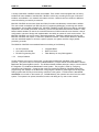
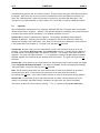
SmartStix is a family of remote products for the OCS. This manual covers programming information for
SmartStix used in CsCAN networks.
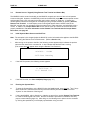
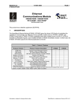
Figure 1.1 - Front View of MiniOCS (Shown on Door in Panel Box)
1.2
MiniOCS and MiniRCS Product Description
1.2.1
Functions and Features
The MiniOCS provides controller, I/O, operator interface, and optional networking capabilities in one unit.
The MiniRCS has the same functionality as the MiniOCS except that it does not have local operator
interface capabilities. Both the MiniRCS and the MiniOCS support a remote operator interface through a
PC connected to the Mini unit’s built-in network or serial port. The remote operator interface (Remote
Text Terminal) is particularly useful when using the MiniRCS, which does not have a physical front panel
screen or keypad.
The MiniOCS is mounted in a panel door; the MiniRCS is designed for backplate mounting. Both the
MiniOCS and the MiniRCS can be used in CsCAN or DeviceNet networks. To use the MiniRCS in a
DeviceNet network, a DeviceNet file can be downloaded from Cscape’s Firmware Update Wizard.
PAGE 10
MAN305-04
15 MAR 2003
CH.1
A variety of MiniOCS / MiniRCS models are available. Each model comes equipped with one factory
installed I/O board. Models of the MiniOCS / MiniRCS, which vary according to the type of I/O board
installed, are available in non-network and network versions. Network versions contain an additional
connector allowing connectivity to networks.
MiniOCS / MiniRCS devices have Serial and CAN (Controller Area Network) communication abilities.
The units contain a standard 9-pin RS-232 port for programming/debugging, monitoring and network
administration from an IBM-compatible PC. MiniOCS / MiniRCS models, which have built-in networking
capabilities, use CsCAN (pronouned “Sea-scan”) protocol and standard CAN network hardware. CANbased network hardware is used in the controllers because of CAN’s automatic error detection, ease of
configuration, low-cost of design and implementation and ability to operate in harsh environments. The
MiniOCS / MiniRCS can also be used in DeviceNet networks. Networking abilities are built-in to the
MiniOCS / MiniRCS and require no external or additional modules. When several MiniOCS / MiniRCS
units are networked together to achieve a specific purpose, the system acts like a large parallelprocessing controller.
The MiniOCS / MiniRCS have standard features consisting of the following:
•
•
•
1.2.2
24 VDC powered
One Internal I/O Module
RS-232 Programming Port
•
•
•
Integrated Bezel
Real-Time Clock
Flash Memory for easy field upgrades
Cscape Software
Cscape Software (pronounced “Sea-scape”) is used with the MiniOCS / MiniRCS, OCS, and RCS
products. (The part number for Cscape is HE500OSW232.) Cscape stands for Control Station Central
Application Programming Environment. The Windows-based software package is easy to use and aids in
the integration of a CAN-based Distributed Control System. The program is used for configuring
controllers and I/O Modules. Cscape is also used for programming MiniOCS / MiniRCS ladder logic,
programming user displays for the MiniOCS, configuring the network for global digital and analog data,
setting system-wide security and monitoring controllers in the system. Provided there is one serial
connection to one node on the network (i.e., CsCAN Network), the operator has control over the entire
system. The operator can upload, download, monitor and debug to any node on the network.
CH.1
1.2.3
15 MAR 2003
PAGE 11
MAN0305-04
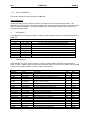
MiniOCS / MiniRCS Specifications
TBD = To Be Determined
Table 1.1 – Physical Specifications
MiniOCS and MiniRCS
Operating Temperature*
0°C to +50°C*
(* Although the MiniOCS / MiniRCS withstands the temperature range of 0°C
to +60°C, such temperatures can decrease the life of the display.
recommended rating is 0°C to +50°C.)
Humidity
NEMA Rating
Primary Power Range
Maximum Power Draw (Non-network
Version)
Maximum Power Draw (Network
Version)
Maximum Inrush Current ((Nonnetwork Version)
Maximum Inrush Current (Network
Version)
Ladder Execution
Typical Execution Speed
CAN Power Range
CAN Power Current
Serial
CAN
Input / Output
Keypad
UL
CE
MiniOCS
Height
Width
Mounting Depth
User Keys (MiniOCS Only)
Display (MiniOCS only)
MiniRCS
Height
Width
Mounting Depth
5% to 95% non-condensing
NEMA 4X
10-30VDC
Mini OCS
200mA max. @ 24VDC
The
Mini RCS
To Be Determined
200mA max. @ 24VDC
900mA max. @ 24VDC for 1mS
900mA max. @ 24VDC for 1mS
To Be Determined
To Be Determined
To Be Determined
2.0ms. per 1K of Boolean logic.
12 – 25 VDC
75mA maximum
Standard 9 pin RS-232 for programming, monitoring, and network
administration from a IBM compatible PC
CsCAN Network / DeviceNet
One factory-installed I/O board per model
10 user-programmable keys + , Esc, Enter and 4 direction keys
Faceplate made of Marnot XL Polyester by Tekra.
Please refer to Compliance Table located at
http://www.heapg.com/Support/compliance.htm
4.4” (111.76mm)
7” (177.80)
2.25” (57.15)
(approximately 2.75” [69.85] including Ground Screw extension)
17
2x20 LCD w/backlight; 3.2mm w x 5.55mm h characters
4.13” (104.78mm)
5.83” (147.98mm)
1.83” (46.48mm)
(approximately 2.33” [59.18] including Ground Screw extension)
PAGE 12
MAN305-04
15 MAR 2003
1.3
MiniOCS / MiniRCS Resources
1.3.1
Overview
CH.1
This section defines the resource limits that a programmer needs to know when writing a program using
the MiniOCS / MiniRCS.
A MiniOCS / MiniRCS combine local I/O (analog and digital), networking, and controller, into a single
product. The MiniOCS also provides an operator interface (display and keypad). The controller portion of
the MiniOCS / MiniRCS is programmed in ladder logic via the Windows-based Cscape (Control Station
Central Application Programming Environment) package. Each MiniOCS / MiniRCS provide a set of
resources for use by the ladder logic control program as indicated in Table 1.2. The table shows the
resources available in MiniOCS / MiniRCS products. Note that although each register type inherently
consists of either 1-bit or 16-bit registers, all registers can be accessed via User Screens and/or Ladder
Code as 1, 8, 16 or 32-bit values or as ASCII character strings.
Table 1.2 - MiniOCS/MiniRCS Resource Limits
%S Registers
%SR Registers
%T Registers
%M Registers
%R Registers
%K Registers
%D Registers
%I Registers
%Q Registers
%AI Registers
%AQ Registers
%IG Registers
%QG Registers
%AIG Registers
%AQG Registers
Network Port
Controllers Per Network
SmartStack I/O Modules
Keypad
Local MiniOCS Display /
Display
Screen Memory
User Screens
Data Fields Per
User Screen
8
192
2048
2048
2048
10
200
2048
2048
512
512
0 / 64 / 0
0 / 64 / 0
0 / 32 / 16
0 / 32 / 16
None / CsCAN / DeviceNet
0 / 253 / 64
1 Slot
16 Keys (Membrane)
The faceplate is made of Marnot XL Polyester by Tekra. The material is
resistant to most corrosive substances found in industrial environments. The
material also holds up well in most industrial conditions. If used outdoors, the
materials can yellow or crack.
Remote Text Terminal for MiniRCS and MiniOCS
2x20 Characters
Text Tables
200
(Text LCD)
64K
Items Per Text Table
20
200
Ladder Code
64K
10
CH.1
1.3.2
15 MAR 2003
PAGE 13
MAN0305-04
Resource Definitions
This section defines the resources listed in Table 1.2.
System Registers
System Registers (%S and %SR) are used to store general OCS or RCS status information. This
information is used internally, and is also available to the operator via the System Menu, using the Control
Station’s display and keypad. The System Registers are also available for User Screens and can be
accessed by Ladder Code.
a.
%S Registers
%S Registers are 1-bit memory locations, containing system status information, implemented as shown in
Table 1.3:
Table 1.3 - %S Registers
Register
Name
Description
%S1
FST_SCN
On during first scan after entering RUN mode
%S2
NET_OK
On if Network is functioning properly
%S3
T_10MS
On for 5 mS; Off for 5 mS
%S4
T_100MS
On for 50 mS; Off for 50 mS
%S5
T_SEC
On for 500 mS; Off for 500 mS
%S6
IO_OK
On if SmartStack I/O is configured properly
%S7
ALW_ON
Always On
%S8
ALW_OFF
Always Off
b.
%SR Registers
%SR Registers are 16-bit memory locations, containing system status information, implemented as
shown in Table 3. Note: Where 2 %SRs are combined to make a 32-bit value, the lower numbered %SR
is the low word, while the higher numbered %SR is the high word.
Register
%SR1
%SR2
%SR3
%SR4
Name
USER_SCR
ALRM_SCR
SYS_SCR
SELF_TEST
%SR5
CS_MODE
%SR6
%SR7
%SR8
%SR9-10
%SR11-12
%SR13-14
%SR15-16
%SR17-18
%SR19-20
%SR21-22
%SR23
%SR24
%SR25
%SR26
%SR27
SCAN_RATE
MIN_RATE
MAX_RATE
EDIT_BUF
LADDER_SIZE
UTXT_SIZE
Reserved
IO_SIZE
NET_SIZE
SD_SIZE
LADDER_CRC
UTXT_CRC
Reserved
IO_CRC
NET_CRC
Table 1.4 - %SR Registers
Description
Current User Screen Number (0=none)
Current Alarm Screen Number (0=none)
Current System Screen Number (0=none)
Bit-Mapped Self-Test Result
Control Station Mode
(0=Idle, 1=Do I/O, 2=Run)
Average Scan Rate (in tenths of mS)
Minimum Scan Rate (in tenths of mS)
Maximum Scan Rate (in tenths of mS)
Data Field Edit Buffer
Ladder Code Size
User Text Screen Table Size
I/O Configuration Table Size
Network Configuration Table Size
Security Data Table Size
Ladder Code CRC
User Text Screen Table CRC
I/O Configuration Table CRC
Network Configuration Table CRC
Min
0
0
0
0
Max
200
200
11
65535
0
2
0
2
4
16
34
0
0
0
0
1000
1000
1000
232-1
64K
64K
64K
32K
65535
65535
65535
65535
PAGE 14
MAN305-04
15 MAR 2003
Register
%SR28
Name
SD_CRC
%SR29
NET_ID
%SR30
NET_BAUD
%SR31
NET_MODE
%SR32
%SR33
LCD_CONT
FKEY_MODE
%SR34
SERIAL_PROT
%SR35-36
%SR37
%SR38
%SR39
%SR40
SERIAL_NUM
MODEL_NUM
ENG_REV
BIOS_REV
FPGA_REV
%SR41
LCD_COLS
%SR42
LCD_ROWS
%SR43
KEY_TYPE
%SR44
%SR45
%SR46
%SR47
%SR48
%SR49
%SR50
%SR51
%SR52
%SR53-54
%SR55
%SR56
%SR57
%SR58
%SR59
%SR60
%SR61
RTC_SEC
RTC_MIN
RTC_HOUR
RTC_DATE
RTC_MON
RTC_YEAR
RTC_DAY
NET_CNT
WDOG_CNT
BAD_LADDER
F_SELF_TEST
LAST_KEY
BAK_LITE
USER_LEDS
S_ENG_REV
S_BIOS_REV
NUM_IDS
%SR62-192
Reserved
Table 1.4 - %SR Registers
Description
Security Data Table CRC
This Station’s Primary Network ID (CsCAN)
This Station’s Primary Network ID (DeviceNet)
Network Baud Rate (CsCAN)
(0=125KB; 1=250KB; 2=500KB; 3=1MB)
Network Baud Rate (DeviceNet)
(0=125KB; 1=250KB; 2=500KB)
Network Mode
(0=Network Not Required; 1=Network Required;
2=Reserved; 3=Network Required and Optimized)
LCD Display Contrast Setting
Function Key Mode (0=Momentary; 1=Toggle)
RS232 Serial Protocol Mode
(0=Firmware Update (RISM); 1=CsCAN; 2=Generic
(Ladder- Controlled); 3=Modbus RTU; 4=Modbus
ASCII)
This Station’s 32-bit Serial Number
This Station’s Binary Model Number
Main CPU Engine Firmware Rev Number x 100
Main CPU BIOS Firmware Rev Number x 100
FPGA Image Rev Number x 10
LCD Text Display Number of Columns
LCD Graphics Display Number of Columns
LCD Text Display Number of Rows
LCD Graphics Display Number of Rows
Keypad Type
(0=16 Keys; 1=17 Keys; 2=32 Keys; 3=36 Keys)
Real-Time-Clock Second
Real-Time-Clock Minute
Real-Time-Clock Hour
Real-Time-Clock Date
Real-Time-Clock Month
Real-Time-Clock Year
Real-Time-Clock Day (1=Sunday)
Network Error Count
Watchdog-Tripped Error Count
Bad Ladder Code Error Index
Filtered Bit-Mapped Self-Test Result
Key Code of Last Key Press or Release
LCD Backlight On/Off Switch (0=Off; 1=On)
User LED Control / Status
Slave CPU Engine Firmware Rev Number x 100
Slave CPU BIOS Firmware Rev Number x 100
This Station’s Number of Network IDs (CsCAN)
This Station’s Number of Network IDs (DeviceNet)
-
CH.1
Min
0
1
0
Max
65535
253
63
0
3
0
2
0
3
0
0
255
1
0
4
0
0
0000
0000
000
20
240
2
128
232-1
65535
9999
9999
255
20
240
4
128
0
3
0
0
0
1
1
1996
1
0
0
0
0
0
0
0
0000
0000
1
1
-
59
59
23
31
12
2095
7
65535
65535
65534
65535
255
1
65535
9999
9999
253
1
-
CH.1
15 MAR 2003
PAGE 15
MAN0305-04
User Registers
User Registers (%T, %M and %R) are used to store application-specific Mini data. This data can be
accessed via User Screens and/or by Ladder Code.
a.
%T Register
A %T Register is a non-retentive 1-bit memory location, used to store application-specific state
information.
b.
%M Registers
A %M Register is a retentive 1-bit memory location, used to store application-specific state information.
c.
%R Registers
A %R Register is a retentive 16-bit memory location, used to store application-specific values.
HMI Registers
HMI Registers (%K and %D) give the user access to the OCS or RCS keypad and display.
The MiniOCS has a membrane keypad and text-based LCD display, allowing the operator to enter and
display general and application-specific information. This same information can be entered and displayed
for the MiniRCS (and MiniOCS if desired) via a remote PC using Cscape’s Remote Display Terminal
function.
a.
%K Registers
A %K Register is a non-retentive 1-bit memory location (contact), used to store the state of a function key
on the Control Station’s keypad. If the function keys are set for momentary mode, a function key’s
associated %K register will be ON as long as the function key is pressed. If the function keys are set for
toggle mode, a function key’s associated %K register will toggle each time the function key is pressed.
b.
%D Registers
A %D Register is a non-retentive 1-bit memory location (coil), which can be turned ON by Ladder Code to
cause the corresponding User or Alarm Screen to be displayed.
c.
User Screens
A User Screen is a combination of fixed text or graphics, along with variable Data Fields (called Graphics
Objects in the MINIOCS), which together fill the LCD display screen. These screens are defined via
Cscape dialogs and are then downloaded and stored into the Control Station’s Flash memory. User
Screens can be selected for display by operator entries on the keypad, or by Ladder Code.
d.
Data Fields
A Data Field is an area on a User Screen where variable data is displayed and edited. The source data
for a Data Field can be any of the Control Station’s Register resources as defined above. The field size
and display format is programmable via Cscape dialogs.
PAGE 16
MAN305-04
e.
15 MAR 2003
CH.1
Text Tables
A Text Table is a list of Text Items, which can be used in a Data Field, to display descriptive words and
phrases to describe the value of a Register, instead of displaying numeric values. A simple example of
this, would allow the strings “OFF” and “ON” to be displayed, instead of 0 and 1, to describe the state of
the %I4 digital input. The maximum number of Text Tables and Text Items per Text Table is shown in
Table 1, but the number can be further limited by overall User Screen memory usage.
Physical I/O Registers
Physical I/O Registers (%I, %Q, %AI and %AQ) give the user access to the Physical I/O Module
data. This data can be accessed via User Screens and/or by Ladder Code.
a.
%I Registers
A %I Register is a 1-bit memory location, which is normally used to store the state of one of the digital
inputs associated with a Physical I/O module. When used in this way, %I registers are non-retentive. All
extra %I registers, which are not associated with physical inputs, are retentive, and can be used just like
%M registers.
b.
%Q Registers
A %Q Register is a non-retentive 1-bit memory location, which is normally used to store the state of one
of the digital outputs associated with a Physical I/O module.
c.
%AI Registers
A %AI Register is a 16-bit memory location, which is normally used to store the value of one of analog
inputs associated with a Physical I/O module. When used in this way, %AI registers are non-retentive.
All extra %AI registers, which are not associated with physical inputs, are retentive, and can be used just
like %R registers.
d.
%AQ Registers
A %AQ Register is a non-retentive 16-bit memory location, which is normally used to store the value of
one of the analog outputs associated with a Physical I/O module.
Global Data I/O Registers
Global Data I/O Registers (%IG, %QG, %AIG and %AQG) give the user access to the Network Port’s
Global I/O data. This data can be accessed via User Screens and/or by Ladder Code.
a.
%IG Registers
A %IG Register is a retentive 1-bit memory location, which is normally used to store a global digital state
obtained from another Control Station on the network.
b.
%QG Registers
A %QG Register is a retentive 1-bit memory location, which is normally used to store a digital state to be
sent as global data to the other Control Stations on the network.
CH.1
c.
15 MAR 2003
PAGE 17
MAN0305-04
%AIG Registers
A %AIG Register is a retentive 16-bit memory location, which is normally used to store a global analog
value obtained from another Control Station on the network.
d.
%AQG Registers
A %AQG Register is a retentive 16-bit memory location, which is normally used to store an analog value
to be sent as global data to the other Control Stations on the network.
e.
Network Port
The CsCAN Network is based on the Bosch Control Area Network (CAN), and implements the CsCAN
Protocol which is designed to take maximum advantage of the global data broadcasting capability of
CAN. Using this network protocol, up to 64 Control Stations can be linked without repeaters, and up to
253 Control Stations can be linked by using 3 repeaters. For more information regarding CsCAN
Protocol, refer to the CsCAN Protocol Specification document.
DeviceNet is an “open” higher layer protocol, which is supported by products from multiple vendors. In an
OCS or RCS, DeviceNet can be loaded as a replacement for the CsCAN Protocol Message Layer, and as
a result, the OCS or RCS becomes a DeviceNet Slave device. Note that the Mini still implements the
CsCAN Protocol Command Layer with respect to the RS-232 programming port. For more information
regarding DeviceNet Protocol, contact the DeviceNet governing body (ODVA).
Ladder Code
The Ladder Code, stores ladder instructions generated by Cscape. This Ladder Code is downloaded and
stored into the Control Station’s Flash memory, to be executed each controller scan, when the controller
is in RUN mode.
1.4
MiniOCS / MiniRCS Models
Because there are several models of MiniOCS / MiniRCS models available, the MiniOCS / MiniRCS can
be used in a wide range of applications. The MiniOCS consists of an Operator Control Station, and the
MiniRCS consists of a Remote Control Station. Each model comes equipped with one factory installed
I/O board. The models vary according to the type of I/O board installed and are available in non-network
and network versions. Network versions contain an additional connector allowing connectivity to CAN
networks. Refer to Additional References on page 18 to locate model-specific information for each Mini.
PAGE 18
MAN305-04
1.5
15 MAR 2003
CH.1
Additional References
For further information regarding products covered in this manual, refer to the following references:
a.
Mini I/O (MAN0581) – Contains a collection of individual data sheets covering model-specific
information.
b.
DeviceNet Implementation Using Control Station Modules (SUP0326) - Covers the
implementation of Control Station products in a DeviceNet network.
c.
Cscape Reference Manual (MAN0313) – Contains topics specifically selected to assist you
through the programming process.
1.6
Technical Support
For user manual updates, contact Technical Services at the following locations:
North America:
(317) 916-4274
www.heapg.com
Europe:
(+) 353-21-4321-266
www.horner-apg.com
CH.2
15 MAR 2003
PAGE 19
MAN0305-04
CHAPTER 2: INSTALLATION
2.1
MiniOCS Mounting Requirements
2.1.1
MiniOCS Mounting Procedures (Installed in a Panel Door)
The MiniOCS is designed for permanent panel mounting. To install the MiniOCS, follow the instructions
below.
1. Prior to mounting the MiniOCS, observe requirements for the panel layout design and adequate
clearances. A checklist is provided on page 25.
2. Cut the host panel as described in the Figure 2.1 - Figure 2.6.
Warning: Make sure the power and network connectors are removed from the MiniOCS.
3. Insert the MiniOCS through the panel cutout (from the front). The gasket material needs to lie
between the host panel and the MiniOCS panel.
4. Install and tighten the mounting clips (provided with the MiniOCS) until the gasket material forms a
tight seal. (See Figure 2.7. )
Caution: Do not over-tighten. Over-tightening can potentially damage the case.
5. Connect the communications, programming, and power cables to the MiniOCS ports using the
provided connectors.
6. Begin configuration procedures for the MiniOCS models.
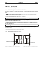
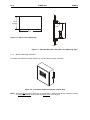
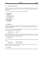
2.1.2
MiniOCS Dimensions and Panel Cut-outs
Network Port
3 3/16
80.96mm
Programming Port
Power Port
Figure 2.1 –Right-end View Network Model
Figure 2.2 - Left-end View Network Model
PAGE 20
MAN0305-04
15 MAR 2003
CH.2
3 3/16
80.96mm
Programming Port
Power Port
Figure 2.3 - Right-end View (Non-Network Model)
Figure 2.4 - Left -end View (Non-Network Model)
5 13/16
147.64mm
I/O Port
2 1/4
57.15mm
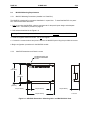
Figure 2.5 – Bottom View
CH.2
15 MAR 2003
PAGE 21
MAN0305-04
3 11/32
84.93mm
6
152.40
Figure 2.6 – Panel Cut-out (MiniOCS)
Figure 2.7 – MiniOCS Mounted in Panel Box using Mounting Clips.
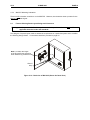
2.1.3
MiniOCS Mounting Orientation
The bases of the MiniOCS model needs to be mounted with the proper orientation.
Figure 2.8 - Orientation of MiniOCS (Shown in Panel Box)
NOTE: There are NO orientation restrictions on the MiniOCS. However, the above orientation provides
for optimum readability of the screen and ease of use of the keypad.
PAGE 22
MAN0305-04
15 MAR 2003
2.2
MiniRCS Mounting Requirements
2.2.1
MiniRCS Mounting Procedures (Installed in a Panel Box)
CH.2
The MiniRCS is designed for permanent installation in a panel box. To install the MiniRCS in a panel
box, use the instructions that follow:
1. Prior to mounting the MiniRCS, observe requirements for the panel layout design and adequate
clearances. A checklist is provided on page 25.
2. Drill holes as described in the Figure 2. 9.
Warning: Make sure the power and network connectors are removed from the MiniRCS.
3. Install and tighten washers and nuts. Do not over-tighten.
4. Connect the communications and power cables to the MiniRCS ports using the provided connectors.
5. Begin configuration procedures for the MiniRCS models.
2.2.2
MiniRCS Dimensions and Panel Cut-outs
MOUNTING HOLES FOR
#6 OR M3.5 HARDWARE
4 PLCS.
4.13
(104.78mm)
3.75
(95.25mm)
0.19
[4.78mm]
0.91 [23.19mm]
4.00 [101.60mm]
1.83 [46.48mm]
5.83 [147.98mm]
Figure 2.9 – MiniRCS Dimensions / Mounting Holes and MiniRCS Side View
001RCS001
CH.2
2.2.3
15 MAR 2003
PAGE 23
MAN0305-04
MiniRCS Mounting Orientation
There are NO orientation restrictions on the MiniRCS. However, the orientation shown provides for the
ease of use of the keypad.
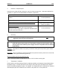
2.3
Factors Affecting Panel Layout Design and Clearances
Warning:
It is important to follow the requirements of the panel manufacturer and to follow
applicable electrical codes and standards.
The designer of a panel layout needs to assess the requirements of a particular system and to consider
the following design factors. A convenient checklist is provided on page 25.
Note: Consider the length
of the Ground Screw extension
when determining clearances.
Ground
strap
Figure 2.10 – Back view of MiniOCS (Shown On Panel Door)
PAGE 24
MAN0305-04
a.
15 MAR 2003
CH.2
Clearance / Adequate Space
Install devices to allow sufficient clearance to open and close the panel door. Note that the MiniOCS is
mounted on a panel door and the MiniRCS is mounted in a panel box.
Table 2.1 – Minimum Clearance Requirements for Panel Box and Door
Minimum Distance between base of device and sides of
cabinet
2 inches (50.80mm)
Minimum Distance between base of device and wiring ducts
If more than one device installed in panel box (or on door):
Minimum Distance between bases of each device
When door is closed:
Minimum distance between device and closed door
(Be sure to allow enough depth for MiniOCS / MiniRCS Model
and Ground Screw Extension.)
b.
1.5 inches (38.10mm)
4 inches between bases of each
device (101.60mm)
2 inches (50.80mm)
Grounding
Warning: Be sure to meet the ground requirements of the panel manufacturer and also meet
applicable electrical codes and standards.
Warning: To provide maximum noise immunity and to insure minimum EMI radiation, the Vsignal (DC power return) need to be connected to earth ground at the power supply.
The user must ensure that the power supply selected is compatible with this method
of grounding.
Panel box: The panel box needs to be properly connected to earth ground to provide a good common
ground reference.
Panel door: Tie a low impedance ground strap between the panel box and the panel door to ensure that
they have the same ground reference (Figure 2.10).
Devices in panel box and on the panel box door:
Use the mounting hardware provided with the device, which includes mounting clips.
c.
Temperature / Ventilation
Ensure that the panel layout design allows for adequate ventilation and maintains the specified ambient
temperature range. Consider the impact on the design of the panel layout if operating at the extreme
ends of the ambient temperature range. For example, if it is determined that a cooling device is required,
allow adequate space and clearances for the device in the panel box or on the panel door.
CH.2
d.
15 MAR 2003
PAGE 25
MAN0305-04
Orientation
Observe guidelines for proper orientation of the bases when mounting the MiniOCS / MiniRCS (page 25).
Proper orientation helps to ensure a good connection when MiniOCS / MiniRCS models are installed into
the devices.
e.
Noise
Consider the impact on the panel layout design and clearance requirements if noise supression devices
are needed. Be sure to maintain an adequate distance between the MiniOCS / MiniRCS and noisy
devices such as relays, motor starters, etc.
Note: Do not route power and signal wires in the same conduit.
2.3.1
Panel Layout Design and Clearance Checklist:
The following list provides highlights of panel layout design factors.
____Meets the electrical code and applicable standards for proper grounding, etc.?
____Meets the panel manufacturer’s requirements for grounding, etc.?
____Is the panel box properly connected to earth ground? Is the panel door properly grounded? Has the
appropriate procedure been followed to properly ground the devices in the panel box and on the
panel door? (See page 25.)
____Are minimum clearance requirements met? (See Table 2.1.) Can the panel door be easily opened
and closed? Is there adequate space between device bases as well as the sides of the panel and
wiring ducts?
____Is the panel box deep enough to accommodate the MiniOCS / MiniRCS. (Be sure to consider the
Ground Screw extension.)
____Are the device bases oriented correctly? (See page 25.) The MiniOCS / MiniRCS devices are
mounted on the door of a panel box.
____Is there adequate ventilation? Is the ambient temperature range maintained? Are cooling or heating
devices required?
____Are noise suppression devices or isolation transformers be required? Is there adequate distance
between the base of the MiniOCS / MiniRCS and noisy devices such as relays or motor starters?
Ensure that power and signal wires are not routed in the same conduit.
____Are there other requirements that impact the particular system, which need to be considered?
Warning: To provide maximum noise immunity and to insure minimum EMI radiation, the Vsignal (DC power return) need to be connected to earth ground at the power supply. The user must
ensure that the power supply selected is compatible with this method of grounding.
PAGE 26
MAN0305-04
15 MAR 2003
2.4
Ports, Connectors, and Wiring
2.4.1
Power, Network, and Programming Ports
CH.2
The MiniOCS / MiniRCS Power, Network, and Programming Ports are shown in Figure 2.11 - Figure 2.12.
for both the network and non-network versions of the MiniOCS / MiniRCS. The MiniOCS / MiniRCS I/O
Module receptacle is located on the bottom.
2.4.2
Primary Power Port
Table 2.2 – Primary Power Port Pins
Signal
Description
Frame Ground
Pin
1
2
3
V+
V-
Input power supply voltage
Input power supply ground
PIN 1
PIN 1
PIN 2
PIN 2
PIN 3
PIN 3
Figure 2.11 - Power Connector
(Primary Power Port)
(Front and Side Views Shown)
Figure 2.12 - As viewed looking at
the Mini
Note: Power Supply Voltage Range is from 10-30 VDC.
Warning: To provide maximum noise immunity and to insure minimum EMI radiation, the V-signal
(DC power return) need to be connected to earth ground at the power supply. The user must ensure
that the power supply selected is compatible with this method of grounding.
DC Power
Supply
+
+
-
MINI
Frame
(Earth)
Ground
Connect DC V- to earth ground at the power supply.
Figure 2.13 - Grounding
CH.2
2.3.3
15 MAR 2003
PAGE 27
MAN0305-04
CAN Network / DeviceNet Network Port and Wiring
Table 2.3 – CAN Port Pins
Signal
Description
VPower CN_L
Signal SHLD
Shield
CN_H
Signal +
V+
Power +
Pin
1
2
3
4
5
1 2
3
4
1
5
V+
CN_H
V-
2
3
4
5
V+
SHLD
CN_L
CN_H
SHLD
CN_L
V-
Figure 2.14 – Network Connector
(CAN Port)
Figure 2.15 – As viewed looking
at the Mini
VCN_L
SHIELD
CN_H
V+
CH.2
VCN_L
SHIELD
CN_H
V+
VCN_L
SHIELD
CN_H
V+
15 MAR 2003
VCN_L
SHIELD
CN_H
V+
PAGE 28
MAN0305-04
121Ω
121Ω
+
12-25VDC
V-
CN_ L
SHIELD
CN_ H
V+
BLU
121Ω
WHT
RED
V+
CN_ H
SHIELD
BLK
RED
RE
D
SHIELD
WHT
121Ω
BLK
BLU
BLK
VCN_ L
CN_ H
V+
SHIELD
VCN_ L
V+
CN_ H
SHIELD
VCN_ L
-
BLK
BLU
BLU
WHT
RED
WHT
RED
SHIELD
SHIELD
+
12-25VDC
Figure 2.16 – CAN Wiring
Note: To optimize CAN network reliability in electrically noisy environments, the CAN power
supply needs to be isolated (dedicated) from the primary power.
a.
1.
2.
3.
4.
5.
CAN Wiring Rules (See Figure 2.16.)
Wire the CAN network in a daisy-chained fashion such that there are exactly two physical endpoints on the network.
The two nodes at the physical end-points need to have 121 ohm 1% terminating resistors
connected across the CN_L and CN_H terminals.
Use data conductors (CN_L and CN_H) that are 24 AWG shielded twisted pair for “thin cable” and
22 AWG shielded twisted pair for “thick cable.” They must also have 120-ohm characteristic
impedance. In typical industrial environments, use a Belden wire #3084A (“thin”). Use #3082A
(“thick”) for network cable lengths greater than 100 meters environments where noise is a concern.
Place data conductors (CN_L and CN_H) into a twisted pair together.
Use power conductors (V- and V+) that are 18 AWG twisted-pair for “thin cable” and 15 AWG
twisted-pair for “thick cable.” Place power conductors (V- and V+) into a twisted pair together.
If local codes require the local CAN power supply to be earth grounded, connect the V- power
conductor to a good earth ground at one place only on the network, preferably at a physical
endpoint. If multiple power supplies are used, only one power supply must have V- connected to
earth ground. The remaining power supplies need to be isolated.
CH.2
6.
15 MAR 2003
PAGE 29
MAN0305-04
For a section of cable between two nodes, the cable shield is connected to the cable shield input at
one end of the cable only.
A CAN network (without repeaters) is limited to 64 nodes (with 63 cable segments) with a maximum
combined cable length of 1500 ft. at 125KBaud.
Up to four CAN network segments, which adhere to the above rules, may be connected together
using three CAN repeaters. In this manner, a CAN network may be extended to 253 nodes with a
total cable distance of 6000 ft. at 125KBaud.
7.
8.
b.
CsCAN or DeviceNet Cable
The 5-wire, multi-conductor copper cable used in CsCAN or DeviceNet network include:
1. Two wires used as a transmission line for network communications.
2. Two wires used to transmit network power.
3. One conductor used as an electromagnetic shield.
Cabling is available in a variety of current -carrying capacities. On a CsCAN or DeviceNet fieldbus, every
device must, at least, power its network transceivers from the network power supply. Some devices draw
all of their power from the network supply.
In CsCAN or DeviceNet, thick and thin cable is used as indicated:
1. Thick cable: Use for long distances and more power. Usually used for Trunk cable.
2. Thin cable: Use for shorter distances. Usually used for drop cables or where cable flexibility is
needed.
Table 2.4 - CsCAN / DeviceNet Cable Specifications
Thick Cable –
general specifications
(e.g., Belden 3082A)
Two twisted shielded pairs –Common axis with drain wire in center.
One signal pair (#18), blue/white; One power power pair (#15) black/red.
Separate aluminized mylar shields around power pair and signal pair.
Overall foil/braid shield with drain wire (#18), bare*. High Speed (Vp=75% min),
low loss, low distortion, data pair (to keep propagation delays to a minimum).
8 amp maximum current capacity. PVC insulation on power pair. Industrial
temperature range. High flexibility.
Thin Cable –
general specifications
(e.g., Belden 3084A)
Two twisted shielded pairs –Common axis with drain wire in center.
One signal pair (#24), blue/white; One power power pair (#22) black/red.
Separate aluminized mylar shields around power pair and signal pair.
Overall foil/braid shield with drain wire (#22), bare*. High Speed (Vp=75% min),
low loss, low distortion, data pair (to keep propagation delays to a minimum).
3 amp maximum current capacity. PVC insulation on power pair. Industrial
temperature range. High flexibility
Bus with limited branching (truckline / dropline)
Not Supported
Nominal 24 VDC ±4%
Network Topology
Redundancy
Network Power for Node
devices
Allowed Nodes (Bridging
excluded)
Data Packet Size
Duplicate Address Detection
Error Detection / Correction
*
64 nodes
0-8 bytes with allowance for message fragmentation
Addresses verified at power-up
CRC – retransmission of message if validity not acknowledged by
recipient.
The drain wire connects shields within the cable and serves as a means to terminate the shield into the
connector.
PAGE 30
MAN0305-04
c.
15 MAR 2003
CH.2
Bus Length
Several factors affect the maximum length of the bus including the accumulated length of drop lines,
cable type, transfer rate and the number of drop lines. Although a branch is limited to one network per
drop, it can have multiple ports. A branch can not exceed 6 meters.
Table 2.5 - CAN Network Baudrate vs. Total Cable Length
Note: The following values apply to both CsCAN or DeviceNetworks except as indicated.
Thick Cable: Network Data Rate
Maximum Total Cable Length
1Mbit / sec. (Does not apply to DeviceNet.)
40m (131 feet)
500Kbit / sec.
100m (328 feet)
250Kbit / sec.
200m (656 feet)
125Kbit / sec.
500m (1,640 feet)
Thin Cable Maximum Total Cable Length
Maximum bus length is independent of network data rate. Maximum bus length is 100m.
Note: Network baud rates above 250Kbit/sec are not recommended for the MiniOCS /
MiniRCS . The potential for a high rate of network messages can cause an unacceptable
increase in the ladder scan rate.
d.
Bus Power and Grounding
When using CsCAN or DeviceNet:
1. A power supply of 24VDC (±4%) at 16A maximum is required for use in a CsCAN / DeviceNet network
2. With thick cable, a single network segment can have a maximum of 8A. To do this, the power supply
needs to be located in the center of two network segments.
3. Thin cable has maximum of 3A.
4. To ground the cable shield, connect to pin 3 as shown in Figure 2.16.
5. If local codes require the local CAN power supply to be earth grounded, connect the V- power
conductor to a good earth ground at one place only on the network, preferably at a physical endpoint.
If multiple power supplies are used, only one power supply must have V- connected to earth ground.
The remaining power supplies need to be isolated.
2.3.4
RS-232 Programming Port and Wiring
Table 2.6 – RS-232 Port Pins
Pin
1
2
3
4
5
6
7
8
9
Signal
DCD
RXD
TXD
DTR
GND
DSR
RTS
CTS
RI
Description
Always high
Received Data
Transmitted Data
Data Terminal Ready
Ground
Data Set Ready
Request to Send
Clear to Send
Ring Indicate
Pin 1
Direction
Out
Out
In
In
Out
In
Out
Out
Pin 9
Figure 2.17 – RS-232 Port
CH.2
a.
15 MAR 2003
PAGE 31
MAN0305-04
RS-232 Communications Wiring
The MiniOCS / MiniRCS features an RS-232 port (Programming/Debug) for connection to a personal
computer. This port is used for the purposes of MiniOCS / MiniRCS programming, configuring,
monitoring, and debugging. This port can also be used for general ladder logic controlled serial
communications to printers, modems, terminals, etc. When ladder has control of this port, it is not
available for programming or debugging. The wiring diagram for the RS-232 ports is shown in Figure
2.18Figure 2.18. For connection between the MiniOCS / MiniRCS and the PC, the use of a shielded,
multiple conductor wire with a maximum length of 15.24 meters (50 feet) enables proper performance.
Note: A shorter cable can be required when used for high-speed MiniOCS / MiniRCS firmware updating.
SHIELDED MULTI CONDUCTOR
OCS RS-232
9-PIN PC COM
DCD 1
1 DCD
RXD 2
2 RXD
TXD 3
3 TXD
DTR 4
4 DTR
GND 5
5 GND
DSR 6
6 DSR
RTS 7
7 RTS
CTS 8
8 CTS
RI 9
9 RI
DB9
MALE
DB9
FEMALE
15.24 METERS MAX
(50 FEET MAX)
Figure 2.18 – MiniOCS / RCS to PC Wiring
2.3.5
Modem Setup
A modem can be used for remote communications between a computer (using Cscape Software) and the
MiniOCS / MiniRCS. The modem must operate at 9600 baud or higher.
PC
Modem
Modem
Telephone
System
Telephone
System
Figure 2.19 – Modem Setup
Mini
PAGE 32
MAN0305-04
15 MAR 2003
CH.2
a. Setup
Setup the modems to match the default serial port characteristics of the MiniOCS / MiniRCS.
9600 baud
8 data bits
No parity
1 stop bit
disable error checking
disable compression
b. Cable Wiring
OCS
MODEM
9-PIN
DCD
RXD
TXD
DTR
GND
DSR
RTS
CTS
RI
N/C
N/C
N/C
N/C
25- PIN
DCD
RXD
TXD
DTR
GND
DSR
RTS
CTS
RI
Figure 2.20 – Modem Wiring
Note: If the modem has a DB25 connector, a 9-to-25-pin adapter may need to be supplied.
The grayed connections
is required.
are used only if hardware handshaking between the controller and modem
The wire type used in not overly critical except where the length of the cable must be between 30 and 50
feet (10 to 15 meters). In all cases, the cable must be shielded multi-conductor with conductors of at
least 20 gauge. The length of the cable must be as short as possible, and in no case, longer than 50 feet
(15 meters).
The modem must be located as close as possible to the OCS, preferably less than one meter. However,
EIA-232 specifications allow for cable runs up to 50 feet (15 meters). If cable lengths longer than 30 feet
(10 meters) are required, a special low capacitance cable must be used.
Warning: Damage can result if the CD and RI lines are connected to each other or to any other signal
on the connector or through the cable to the other unit.
Warning: To connect a modem to the MiniOCS / MiniRCS the controller to modem cable must be
constructed or purchased. Using a Null Modem cable can cause damage to the MiniOCS / MiniRCS,
modem or both.
CH.2
15 MAR 2003
PAGE 33
MAN0305-04
c. Recommended Modem
Selection of a telephone modem for use with the OCS is highly dependent on environment. For a
relatively benign, low-noise environment, an off-the-shelf external modem like a U.S. Robotics Sportster
Modem can work well. For a more industrial environment, however, it is appropriate to use a telephone
modem designed for that environment. Manufacturers such as Datalinc and Sixnet have models, which
have been known to work in more harsh environments, at a higher cost. If a modem is used, which is not
appropriate for the environment, there may be little that can be done to correct the situation other than
change to a more appropriate model.
For detailed information regarding the use of modems with Control Station Products, contact Technical
Support. (See page 18.) You can also find specific application information (cabling, modem commands,
etc.) in the Cscape Help file as well.
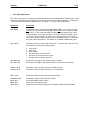
2.5
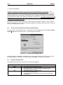
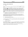
Selecting DeviceNet Network (Firmware Update Wizard)
To use the OCS in a DeviceNet network, use Cscape’s Firmware Update Wizard. Select File, Firmware
Update Wizard from the pull-down menu. The following screen appears.
Figure 2.21 – Using Firmware Update Wizard
Select the product type (MiniOCS or MiniRCS) using the pull-down menu and click on the circle next to
the desired network. Press OK. On the next screen, press Send. Firmware is now updated.
2.6
MiniOCS / MiniRCS LEDs
The following LED information is provided for the MiniOCS / MiniRCS.
Table 2.7 - LEDs
LED
RUN
OK
•
•
•
•
•
•
MiniOCS / MiniRCS
OFF indicates OCS is in IDLE/STOP mode.
Flashing indicates DO / IO mode or RUN with no ladder program.
ON indicates ladder code running.
OFF indicates one or more self-tests failed.
ON indicates all self-tests passed.
FLASHING indicates all self-tests passed and one or more I/O points is
currently forced.
PAGE 34
MAN0305-04
15 MAR 2003
CH.2
MiniOCS LED status is indicated on the physical unit as shown in the following figure.
OK
Esc
RUN
1
QZ
2
ABC
3
DEF
4
GHI
F1
F2
F3
F4
6
7
8
9
MNO
F6
PRS
F7
TUV
F8
WXY
F9
5
+/-
JKL
Enter
F5
0
F10
System
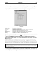
Figure 2.22 – MiniOCS LEDs
The MiniRCS LEDs are also viewed by looking at the physical unit. They are not viewable from a remote
screen.
mini OCS/RCS
OPERATOR CONTROL STATION
OK
RUN
NETWORK
V+
CAN_H
SHIELD
CAN_L
VINPUT
POWER
9-30VDC
COM
PORT
001RCS002
Figure 2.23 – MiniRCS LEDs (I/O Connections Not Shown)
CH.2
2.7
15 MAR 2003
PAGE 35
MAN0305-04
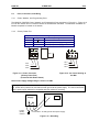
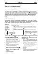
Mini Battery Replacement
The following instructions apply to the MiniOCS and MiniRCS.
1.
2.
3.
4.
5.
6.
Disconnect power from the unit.
Remove ground screw (item #1) from back of unit.
Remove back cover (item #2) by carefully pressing in on one corner locking tab and lifting back
cover to disengage the locking tab. Repeat this for all four corners.
Unscrew the grounding spacer (item #3) using a ¼” Hex nut driver.
Gently lift up and remove the I/O board (item #4) from the three snap top fasteners on the CPU
board.
Once the CPU board is exposed locate the battery (item #5, U7). Remove the battery by prying
up slightly on each end until it lifts free. Dispose of the battery.
Warning: Disposal of lithium batteries must be done in accordance with federal, state, and local
regulations. Be sure to consult with the appropriate regulatory agencies before disposing batteries. In
addition, do not re-charge, disassemble, heat or incinerate lithium batteries.
7.
Replace the battery with HE500BAT005 noting the polarity tab at one end of the battery. Use
care when replacing the battery that this tab is located in the right direction. Use only the authorized
battery part number.
Warning: Do not make substitutions for the battery. Be sure to only use the authorized part number
to replace the battery.
8.
Reassemble the Mini unit by first replacing the I/O board then replacing the ¼” hex spacer. It is
recommended that Loctite222MS Threadlocker or an equivalent be applied to the male threads of item
#xx before reassembling. Line up the back cover with ground hole over the ground spacer and press back
in place. Make sure all four locking tabs of the back cover snap into place. Reconnect the ground wire.
Follow the instructions in the units’ manual for powering up the Mini and restoring it to operation.
5
4
2
1
3
OR
Figure 2.24 – Battery Replacement
PAGE 36
MAN0305-04
15 MAR 2003
NOTES
CH.2
CH.3
15 MAR 2003
PAGE 37
MAN0305-04
CHAPTER 3: SYSTEM MENU
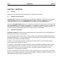
3.1
General
Chapter Three describes the System Menu for the MiniOCS / MiniRCS.
The System Menu is used to access and edit information using the MiniOCS front panel or using the
Remote Text Terminal, which is a feature available in both the MiniOCS and the MiniRCS. The Remote
Text Terminal is particularly useful when using the MiniRCS, because the MiniRCS does not have a
physical front panel display screen or keypad. For more information, see page 45.
The following list contains examples of parameters that can be set using the System Menu:
•
•
•
•
•
•
3.2
Network ID
Network Baud
RS232 Mode
Time/Date
LCD contrast
Fkeys mode
Navigating Through the System Menu
Prior to configuration, it is important to know how to navigate through the System Menu using the
following guidelines.
1.
2.
3.
Pressing the ↑ and ↓ keys scroll up or down through the menu options.
Pressing the Enter key selects the system screen that the indicator arrow is pointing to.
Once in a system screen, press ESC (if not currently modifying a field) to return to the main
System Menu.
3.3
Editing System Menu Screen Fields
Prior to configuration, it is important to know how to edit the System Menu screen fields using the
following guidelines.
1.
2.
3.
Some fields in the system screens are editable; others are not editable. The MiniOCS / MiniRCS
model indicates an editable field with a solid cursor (_) under the first character in the field.
To change a value in an editable field, press the Enter key to select edit mode. The MiniOCS /
MiniRCS model indicates edit mode by displaying a flashing block cursor.
In edit mode, the fields require one of the following methods for modifying the value. Refer to the
field description to determine which method to use.
•
•
•
4.
5.
Enumerated entry
Numeric entry
Bar graph entry
- use ↑ and ↓ keys to select appropriate value.
- use Numeric keys or ↑ and ↓ keys on the appropriate digit.
- use ← and → keys to adjust value.
After the value is correctly entered, press the Enter key to accept the value.
Should the user not wish to accept the value before the Enter key is pressed, the ESC key may
be pressed instead. This action restores the original value to the display. The MiniOCS /
MiniRCS model also immediately exits edit mode; however, the Text models remains in edit
mode with the original value and requires the Enter key to be pressed to exit.
PAGE 38
MAN0305-04
3.4
15 MAR 2003
CH.3
Remote Screen / Keypad (Using Remote Text Terminal and Status Bar)
The MiniRCS has the same functionality as the MiniOCS except that it does not have a local operator
screen and keypad. However, the MiniRCS (as well as the MiniOCS) supports a remote operator screen
and keypad through a PC connected to the Mini unit’s built-in network or serial port. If desired, the
remote operator interface and keypad can be displayed (using Cscape software) by pressing Screens,
Remote Text Terminal. A virtual display screen and keypad appear that are similar to that of the
MiniOCS, and the user can navigate through the system menu, make selections, and edit fields using a
mouse. In addition, the Cscape Status Bar can be used as a tool to ensure that communications are
properly established. For more information on the Remote Test Terminal and the Cscape Status
Bar feature, see page 45.
3.5
Initial System Menu Screens and Self-Test
Note: The examples in this chapter depict the MiniOCS, but the information also applies to the MiniRCS
when using the Remote Text Terminal screen. (Refer to Section 3.4.)
1.
After turning on the power to the Mini, the following screen appears which indicates the product
name and the network it is connected to. It also indicates that the Self-Test is running.
(This screen does not appear when using the Remote Text Terminal.)
MiniOCS – CsCAN
Self-Test Running
a.
If the Self-Test passes, the following screen appears:
** Self-Test **
**** Passed ****
b.
If the Self-Test fails, see View OCS(RCS) Diags (page 41.)
3.6
Entering the System Menu
a.
To enter the System Menu on the MiniOCS using the local keypad, press both the ↑ and ↓ keys
at the same time. Notice that the two keys are surrounded by a white outline and the word
“System” on the silkscreen of the keypad.
b.
If using the MiniRCS, refer to Section 4.1 (starting on page 45) to use the Remote Text Terminal
to create a virtual keypad and screen. Be sure to follow the procedures to establish and verify
proper communications (page 46). After doing so, the following menu options can be accessed
by clicking the specified key in the display representation using a mouse.
CH.3
3.7
15 MAR 2003
PAGE 39
MAN0305-04
System Menu Option Screens
In addition to providing access to the MiniOCS / MiniRCS, configuration parameters, the System Menu
also provides power-up and runtime status. For brevity, both configuration and status fields are covered
in this section
There are up to ten different menu options, which include the following:
•
•
•
•
•
•
•
•
•
•
Set Network ID
Set Network Baud
Set Contrast
View OCS(RCS) Status
View OCS(RCS) Diags
View I/O LEDs
View OCS(RCS) Model
Set Fkeys Mode
Set RS232 Mode.
Set Time/Date
•
Set Network ID
This screen contains two fields. The first field contains the current network status. The second field
contains the current Network ID of the model. The second field is numerically editable and is used to
configure the Network ID.
Each unit on the network needs a unique ID number. The correct ID number should be entered here
before physically attaching the unit to the network.
Cscan model:
DeviceNet model:
[ 1 - 253 ]
[ 0 - 63 ]
Note: If the Network ID setting is changed, the unit stops executing the ladder code (for up to 1 second)
while the network is re-tested. If the “Network OK?” status changes from “Yes” to “No,” the new Network
ID is a duplicate, and another ID needs to be selected.
•
Set Network Baud
This screen contains an editable enumerated field allowing the user to select the current baud rate of the
network.
Cscan model:
DeviceNet model:
[125K, 250K, 500K, 1M]
[125K, 250K, 500K]
Note: All devices on the network must be at the same baud rate. A device configured for the wrong
baud rate may shut down the network entirely.
•
Set Contrast
This menu contains an editable bar graph entry allowing the user to set the contrast of the LCD display.
PAGE 40
MAN0305-04
•
15 MAR 2003
CH.3
View OCS (RCS) Status
This screen contains both a single enumerated editable field that sets the MiniOCS / MiniRCS scan mode
and status fields that display information about the internal state of the MiniOCS/ MiniRCS. Pressing the
↑ and ↓ keys scrolls through the different items. Pressing Esc returns to the System Menu.
Parameter
Description
OCS Mode
Displays the current scanning mode (Idle, Run, DoIO). In Idle mode, the I/O is
not scanned and the OCS ladder program does not execute. The green “RUN”
LED is OFF. In Run mode, the ladder program executes and the green “RUN”
LED illuminates. DoIO mode is similar to Run mode, except the ladder logic is
not solved. When the OCS is in DoIO mode, the user is able to exercise all of
the I/O from Cscape, without interference from the ladder program. In this mode
the green “RUN” LED flashes. This feature is a valuable troubleshooting tool.
Scan-Rate
Shows the number of milliseconds for the scan. The scan-rate is the sum of the
time required to execute the following items:
a.
b.
c.
d.
e.
f.
Scan inputs
Solve logic
Write outputs
Handle network communications
Handle host communications request
Process data for operator interface
OCS Net Use
All Net Use
Shows the percentage of the network used by the Mini.
Shows the percentage of the network used by all devices on the network.
Ladder Size
Config Size
Shows the number of bytes used by the ladder program.
Shows the number of bytes used by the I/O configuration
Text Size
Shows the number of bytes used by the text screens
Firmware Rev
BIOS Rev
FPGA Rev
Self-Test
Shows the execution engine firmware version.
Shows the BIOS firmware revision.
Shows the FPGA Image version.
Shows if the power-up self-test passed or failed by displaying Ok or Fault.
CH.3
•
15 MAR 2003
PAGE 41
MAN0305-04
View OCS(RCS) Diags
This screen displays a list of self-test diagnostics results (no editable fields). Each item describes a test
and shows a result of Ok if the test passed or Fault/Warn if an error was found while running the test.
Fault indications will prevent the loaded application from running. Warn(ing) indications allow the
application to run but inform the user that a condition exists that needs correction.
System BIOS - This test checks for a valid BIOS portion of the controller firmware.
Ok
The loaded BIOS firmware is valid
Fault The loaded BIOS is invalid.
(Engine) Firmware - This test validates the controller firmware.
Ok
The firmware is valid.
Fault The controller firmware is invalid.
User Program - This tests for a valid user program and configuration data.
Ok
The user program and configuration is valid.
Fault The user program and/or configuration are not valid.
System RAM - This test checks the functionality of the controller RAM at power up.
Ok
The RAM is functioning correctly.
Fault The RAM is not functioning correctly.
Logic Error Ok
Fault
This test checks for problems with the user program while running.
No errors have been encountered while running a user program.
Indicates the user program contained an instruction that was invalid or unsupported.
W-Dog Trips - This test checks for resets caused by hardware faults, power brownouts or large amounts
of electrical interference.
0
No unintentional resets have occurred.
xx
Indicates a fault with xx showing the number of occurrences.
Net Errors 0
xx
This test checks for abnormal network operations while running. (Network models only.)
No network errors were counted
Indicate serious networking problems exist, xx indicates the number of occurrences.
Network State - This test checks that the network sub-system is powered and operating correctly.
(Network models only.)
Ok
The network system is receiving power and has determined other devices are
communicating on the network.
Warn Power is not being applied to the network or no other devices were found to be
communicating on the network.
Network ID Ok
Warn
This test checks that the network ID is valid. (Network models only.)
The network ID is valid.
The network ID is not valid for the selected protocol.
Dup Net ID Ok
Warn
This test checks for duplicate IDs on a network. (Network models only.)
This controller's ID was not found to be a duplicate.
Another controller on the network was found with the same ID as this controller.
PAGE 42
MAN0305-04
15 MAR 2003
CH.3
DeviceNet In - (DeviceNet model only.)
Ok
DeviceNet master is maintaining a polled connection and not sending IDLE.
Warn The DeviceNet master is no longer maintaining a polled connection or sending IDLE.
(IDLE is a network state in which ‘some’ masters maintain a polled connection but sends
zero data if an associated PLC controller is in IDLE mode. Refer to Master
documentation for more information.)
Clock Error Ok
Warn
This test checks that the real time clock contains valid data.
The real time clock contains valid data.
Indicates invalid data in the real time clock.
I/O System -
This test checks that the configured (downloaded) model number matches the physical
I/O module installed in the controller.
The configured model number matches the installed I/O module.
Indicates the configured model number does not match the installed I/O module.
(See View OCS(RCS) Model system screen for more information.)
Ok
Warn
•
View I/O LEDs
The View I/O LEDs simulate the LEDs and show the statuses of the first 16 %I and first 16 %Q registers.
•
View OCS(RCS) Model
The View OCS(RCS) Model screen allows the user to view the MiniOCS / MiniRCS model number.
When viewing the model number, the following status screens are possible. Note the term OCSxxx (or
RCSxxx) refers to the MiniOCS (or MiniRCS) model number such as OCS082 (or RCS082).
a.
b.
c.
d.
e.
f.
g.
h.
If the Mini model number is not configured and no I/O module is installed, the message
" I/O: Empty” is displayed.
If the Mini model number is not configured but has an I/O module installed, the message
"+Mini OCSxxx (or RCSxx)" is displayed.
If the Mini model number is configured but no I/O module is installed, the message
"-I/O Missing" is displayed.
If the configured Mini model number does not match the installed I/O module, the message
"?Mini OCSxxx (or RCSxx)" is displayed.
If the installed I/O module is not supported by the Mini firmware, the message
“*Unsupported” is displayed. The module is either defective or an Engine firmware upgrade is
required to support the module.
If the installed I/O module has erroneous or outdated firmware in it, the message
“fMini OCSxxx (or RCSxx)" is displayed. The module is either defective or a Module firmware
upgrade is required.
If the installed I/O module has a configuration error, the message
"cMini OCSxxx (or RCSxx)" is displayed. The configuration data for that module is incorrect.
If the configured Mini model number matches the installed I/O module, the message
" Mini OCSxxx (or RCSxx)" is displayed.
CH.3
•
15 MAR 2003
PAGE 43
MAN0305-04
Set FKeys Mode
This screen contains an editable enumerated field that allows the Function keys to be configured to
operate in one of two modes. When a function key is pressed, it can TOGGLE the point associated with
the key or it can MOMENTARILY turn the point ON when the key is pressed.
•
Set RS232 Mode
This screen contains an editable enumerated field that allows the mode of the serial port to be set to one
of two modes. The CsCAN mode allows Csape to connect to the serial port for uploads, downloads,
monitoring and control. The Update mode allows a firmware update and factory test utility to be used.
When Update mode is selected, the firmware is ready to download when the OK LED flashes. When
using Cscape to perform firmware updates, the “Update” mode is not necessary.
•
Set Time/Date
This screen contains two editable enumerated fields for displaying and modifying the Mini’s time and
date. Each field is subdivided and allows the ↑ and ↓ key to modify the value.
PAGE 44
MAN0305-04
15 MAR 2003
NOTES
CH.3
CH.4
15 MAR 2003
PAGE 45
MAN0305-04
CHAPTER 4: KEYPAD AND SCREEN
4.1
Remote Screen and Keypad Capability
4.1.1
Remote Text Terminal
The MiniRCS has the same functionality as the MiniOCS except that it does not have a local operator
screen and keypad. However, the MiniRCS (as well as the MiniOCS) supports a remote operator screen
and keypad through a PC connected to the Mini unit’s built-in network or serial port. The remote operator
interface and keypad can be displayed using Cscape software by pressing Screens, Remote Text
Terminal. A virtual display screen and keypad appear that are similar to the MiniOCS physical front
panel, and the user can navigate through various screens, make selections, and edit fields using a
mouse.
4.1.2
Cscape Status Bar
When the MiniOCS/ MiniRCS is connected to a PC using Cscape software, and the Remote Text
Terminal feature is selected, a Cscape Status Bar appears at the bottom of the screen. The Cscape
Status Bar can be used to determine if communications have been established between the Mini and the
Cscape program. Components of the Cscape Status Bar are explained in page 45.
Message Line contains Cscape
messages sent by
the programs.
The contents of
these messages
are context
sensitive. The
Message line can
be empty.
Equal Indicator – indicates whether the current program in Cscape is equal to the program
stored in the Target Controller.
•
If Equal, the program in Cscape is the same as the program stored in the Target
Controller.
•
If Not Equal, the program in Cscape is not the same as the program stored in the Target
Controller.
•
If Unknown, there may have been a change since the last time the program in Cscape
was compared to the Target Controller.
File Modified Indicator - indicates that the file in
the selected window has been modified but has
not been saved.
Current User indicates who is logged
(for security purposes).
Ready
User: NONE
HE500OCS061-CsCAN (Model=)
Controller Model - Network (Model Confirmation)
•
Controller Model indicates the MiniOCS or MiniRCS
for which the program in Cscape is configured.
•
Network indicates the type of network that the program
in Cscape expects to us e (e.g., CsCAN or DeviceNet).
•
(Model Confirmation) provides the following
indications:
•
(Model=) - the actual Target Controller matches the
configured Controller Model and Network.
•
(Model Not=) – the actual Target Controller does not
match the configured Controller Model and Network.
•
•
Equal
Local :1 Target :2(R) [no forces]
MOD
Communications Status - indicates the current status of the
“pass through” Connector.
•
Local: xx – indicates the Network ID of the Mini to which
the Cscape program is physically connected through its
serial port. It can serve as a “pass through” device to other
nodes on the network.
•
Target: yy(R) – indicates the Network ID of the Mini with
which the Cscape program is exchanging data.
Note: The Local unit and Target unit can be the
same unit or they can be separate units.
The following are status indicators:
(Model ?) – there may have been a change since the
last time the Target Controller was compared to the
configured
Controller Model and Network.
(R) – Running
(D) - Do I/o
(I) – Idle
(?) – Cscape is not communicating with the remote unit.
[no forces] – indicates no I/O has been forced.
PAGE 46
MAN0305-04
15 MAR 2003
CH.4
4.1.3
Establishing Communications using the Remote Text Terminal
1.
2.
Start Cscape software. Press Screens, Remote Text Terminal.
Establish communications between the Cscape program and Mini by pressing Controller, Set
Network Target ID. Set the Target ID.
Again, select Controller, Configure I/O. Follow the procedures specified in Chapter Five:
Configuration.
Download the program from Cscape to the Mini by pressing Program, Download.
Check the Cscape Status Bar as described in Section 4.1.2 to ensure that the program in
Cscape matches the program downloaded to the Mini model. Be sure to check the Status Bar
often. Another way to check that the download occurred is to press Program, Verify.
Click on the System Key in the display representation and continue the procedures to enter the
system menu beginning on page 38.
3.
4.
5.
6.
4.2
Keypad Description
The MiniOCS keypad contains 10 user-programmable keys, Esc, Enter and four direction keys. The
user-programmable keys, or function keys, also serve the purpose of numeric and alphabetic character
entry. Function keys F1-F10 are available (%K registers). Depending on the configuration of the
MiniOCS and the field needing to be edited, the MiniOCS automatically knows what type of digit or
alphanumeric character needs to be entered.
The MiniOCS keypad also contains four direction keys. The ↑ and ↓ keys contain split fields. The ↑ key
also contains the +/- function. The ↓ key also contains the . function. Similar to the operation of the
function keys, the MiniOCS automatically knows if a decimal point or a positive or negative indicator is
required. The ↑ and ↓ keys are also used to increment and decrement fields, respectively. The ← and →
keys are used to move the cursor from one character to another in an editable field and to switch from
one editable field to another editable field.
OK
Esc
RUN
1
QZ
F1
6 MNO
F6
2
ABC
F2
7
PRS
F7
3
DEF
F3
8
TUV
F8
4
GHI
F4
9
WXY
F9
5
JKL
+/-
Enter
F5
0
F10
System
Figure 4.1 - MiniOCS Keypad
The MiniOCS features an Esc and an Enter key. The Esc key is used to exit out of a number of
different menus and fields or abort an editing operation. The Enter key is used to select a field for
editing and for sending data to the MiniOCS. The Enter key can also be used to escape out of some
selected fields.
CH.4
15 MAR 2003
PAGE 47
MAN0305-04
The MiniOCS keypad has “OK” and “RUN” indicators. These indicators are green LEDs that are built into
the keypad. When there are no errors present in the MiniOCS and the Self-Tests have “passed,” the
green “OK” LED illuminates. When the controller is running logic, the RUN LED illuminates. If the
controller is in the RUN mode with no logic loaded or if it is in the DO I/O mode, the RUN LED flashes.
4.3
Operation
When the MiniOCS unit first powers-up, it displays “MiniOCS Self-Test In Progress.”Next, the message
“MiniOCS Self-Tests In Progress...” appears. After the Mini displays this message, the unit performs tests
to examine the current state of the network. Four different scenarios can occur:
Scenario #1: No power is supplied to the CAN port. The message “No Network Power Network
Disabled” is displayed. Assuming the controller is configured to require the network, the OCS then
displays the message “Self-Tests Failed.” Also, there is a Fault Code of 80 displayed in “View OCS Info”
in the System Menu (see Chapter 3). The green “OK” light does not illuminate.
Scenario #2: No other units are on the CAN network (or this is the first device to power-up on the
network). The message "Waiting for Net: F1 = Disable Net" is shown. If another device is placed on
the CAN network, the message clears and operation continues. The message “Self-Tests Passed” is
displayed. The green “OK” light illuminates. If F1 is pressed the message “No Net Response Network
Disabled” appears and is followed by the message “Self-Tests Failed”. The green “OK” light does not
illuminate.
Scenario #3: If a unit powers-up and finds another unit with the same node number as itself, the display
shows "Duplicate ID Network Disabled". The network is disabled, and the unit displays the message
“Self-Tests Failed.” The green “OK” light does not illuminate.
Note: The ID checking works when one of two devices with the same ID is powered-up more than 1
second before the other. If both devices are powered-up at the same time, this method of
ID checking may not work. In this case, the Mini continues to check for duplicate IDs during operation.
Scenario #4: If a unit powers up and it has network power, and other units are powered up on the
network, the message “Self-Tests Passed” is displayed, and the green “OK” light is illuminated.
At any time, the Mini unit can be reset by pressing: ↑ + F1 + F2 (press the keys at the same time)
PAGE 48
MAN0305-04
4.4
15 MAR 2003
CH.4
User Screens
In the normal operating mode there are a set of user-defined screens that can be scrolled through using
the ↑ and ↓ keys.
If the ladder program energizes a text coil, the screen associated with this coil is displayed and overrides
the "normal" user screens. This is designed to show alarm conditions or to display other ladder-detected
events. When the text coil is de-energized, the previous screen that was being viewed before the alarm
is returned.
If the screen contains an editable field, the user can press the Enter key to enter the edit mode. When
in edit mode, a cursor appears on one digit of the editable field. Use the direction keys (← and →) to
move to the cursor to the desired position. Use the ↑ and ↓ keys to increment or decrement the digit or
enter the number/data with the alphanumeric keys.
If there is more than one field on the screen needing to be edited, use the direction keys (← and →) to
move the cursor to the desired location.
The value chosen by the user may not exceed the minimum or maximum set by the user program. If the
user tries to exceed the maximum point or enter a value below the minimum point, the value does not
change.
Note: If the MiniOCS displays “>>>>>>” in a text field, the value is too big to display in the field or is
above the maximum for an editable field. If the MINI displays “<<<<” in a text field, the value is too small
to display or is below the minimum for an editable field.
4.4.1
Cursor Types
There are three different cursor types, which may show on the display:
a.
b.
c.
Solid underline
Blinking block
Blinking underline
A solid underline cursor appears under an editable field which is not being edited yet. The ← key and the
→ key can be used to move this type of cursor to select a different editable field, if required. Press Enter
to start editing the selected field. This causes a blinking block cursor to appear.
A blinking block cursor appears in an editable field when Enter is first pressed to start editing the field.
The blinking block cursor indicates that the field will be cleared when a numeric (or alphanumeric for an
ASCII field) key is pressed. This allows a new value to be entered for the field just as it would be entered
on a PC keyboard or a calculator. If a direction key (←, →,↑,↓) is pressed, the cursor changes from a
blinking block to a blinking underline, and single-digit edit mode is entered.
A blinking underline cursor appears under an editable field which is being edited in single digit edit mode.
In this mode, the digit (or character) above the cursor can be modified individually. This can be done by
pressing ↑ or ↓ (increments or decrements) or by pressing a numeric (or alphanumeric) key. Pressing ←
or → moves the cursor to the previous or next digit (or character).
CH.5
15 MAR 2003
PAGE 49
MAN0305-04
CHAPTER 5: MINI CONFIGURATION
5.1
General
Chapter Five provides preliminary configuration procedures that are applicable to all MiniOCS / MiniRCS
models.
Remote Screen Usage for the the MiniRCS: The MiniRCS has the same functionality as the MiniOCS
except that it does not have a local operator screen and keypad. However, the MiniRCS supports a
remote operator screen and keypad. through a PC connected to the Mini unit’s built-in network. If
desired, the remote operator interface and keypad can be displayed (using Cscape software) by pressing
Screens, Remote Text Terminal. A virtual display screen and keypad appears that is similar to that of
the MiniOCS. In addition, a Status Bar can be used as a tool to ensure that communications are properly
established. For more information on the Remote Test Terminal and the Status Bar feature, se e
page 45.
Note: The examples in this chapter depict the MiniOCS, but the information also applies to the
MiniRCS when using the Remote Text Terminal screen.
The MiniOCS / MiniRCS models use Cscape Software for configuration. General information is also
provided pertaining to the screens that the user encounters when configuring specific modules. In
addition, each MiniOCS / MiniRCS model has its own data sheet which covers specifications, wiring and
other pertinent information. (See page 18.)
5.2
Preliminary Configuration Procedures
1. The MiniOCS / MiniRCS configuration is accomplished through the Configure Controller Type Dialog.
Note: The configuration examples in this chapter depict the MiniOCS, but the procedures also apply to
the MiniRCS as well.
a.
Using Auto Configuration
From the Main Menu, select Controller|Configure for the following dialog. If the desired MiniOCS /
MiniRCS is physically connected to the PC, press Auto Config. A dialog box appears and indicates that
settings will be deleted from currently configured models. If OK, press Yes. Then press OK.
To obtain a description of the MiniOCS / MiniRCS model, double-click on the box (or press the top
Config button) to select the desired controller from the pull-down menu.
PAGE 50
MAN0305-04
15 MAR 2003
CH.5
Figure 5.1
Note: The configuration examples in this chapter depict the MiniOCS, but the procedures also apply to
the MiniRCS.
b.
Manual Selection of MiniOCS / MiniRCS Model and Obtaining a Description of the Model
Figure 5.2
CH.5
15 MAR 2003
PAGE 51
MAN0305-04
If a different controller is installed, select the MiniOCS / MiniRCS by double-clicking on the box (or press
the top Config button) and select the desired controller from the pull-down menu.
Figure 5.3
Note: The configuration examples in this chapter depict the MiniOCS, but the procedures also apply to
the MiniRCS.
Using pull-down menus, select either a network version of the MiniOCS / MiniRCS (MiniOCS / MiniRCS
– CsCAN) or a non-network version (MiniOCS / MiniRCS – No net). Then, select the MiniOCS /
MiniRCS model that is going to be configured. A description of the selected model is provided on this
screen. Press OK.
2. The following screen appears.
Figure 5.4
PAGE 52
MAN0305-04
15 MAR 2003
CH.5
3. To view the registers associated with the MiniOCS / MiniRCS model, press the lower Config button.
a. A screen appears showing the I/O Map for the MiniOCS / MiniRCS model selected. The user (i.e.,
programmer) needs to view the I/O Map to determine which registers are assigned to the model.
Figure 5.5
Model number:
Description:
Type:
Starting/Ending :
Number:
Provides the I/O part number.
Describes the number of input and output channels and other key
characteristics of the module.
Displays the register types assigned to the module.
Denotes the starting and ending locations of the register type.
Indicates the quantity for a particular register type.
Note: Do not confuse the described number of input and output channels with the numbers found in the
Type column (i.e., %I and %Q). The numbers do not necessarily match.
b. Selecting the I/O Map tab provides information about the I/O registers, which are assigned to a
specific MiniOCS / MiniRCS Module. The I/O Map is determined by the model number. The I/O Map is
not edited by the user.
The Module Setup is used in applications where it is necessary to change the default states of the
outputs when the controller (e.g., OCS100) enters idle/stop mode. The default turns the outputs OFF
when the controller enters idle/stop mode. By selecting the Module Setup tab, each output can be set to
either turn ON, turn OFF or to hold the last state. Generally, most applications use the default settings.
Warning: The default turns the outputs OFF when the controller enters idle/stop mode. To avoid injury
of personnel or damages to equipment, exercise extreme caution when changing the default setting
using the Module Setup tab.
4. There is no further configuration required for most MiniOCS / MiniRCS models. The exceptions are
the High Speed Counter MiniOCS / MiniRCS Models which include 033/063 and 034/064. Refer to the
SmartStack High Speed Counter Supplement for further information.
CH.6
MAN0305-04
15 MAR 2003
PAGE 53
CHAPTER 6: SMARTSTIX
6.1
General
Chapter Six covers SmartStix I/O programming and configuration parameters.
6.2
SmartStix I/O Introduction
SmartStix I/O is a family of low-cost Remote I/O devices that are designed to extend the I/O capabilities
of Control Station products, such as MiniOCS, OCS and RCS. SmartStix I/O Modules connect to
Control Station devices via the CsCAN Network and communicate using CsCAN Protocol.
Devices with CsCAN Network ports that are connected to each other for peer-to-peer communication are
called CsCAN Nodes. A device that is connected to a CsCAN Node’s programming port for master-slave
supervisory communication is called a CsCAN Host. For example, SmartStix I/O Modules and OCS
Control Stations are CsCAN Nodes while a PC running Cscape is a CsCAN Host.
6.3
SmartStix I/O Modules
SmartStix I/O Modules are devices that exchange data with Control Stations over the CsCAN Network
and control and monitor physical I/O points.
To control physical outputs, data is sent by a Control Station to the SmartStix I/O Module using CsCAN
Directed Data Messages. To monitor physical inputs, a Control Station receives data from the SmartStix
I/O Module using CsCAN Global Data Messages.
In addition to I/O control and monitoring, configuration and status data can be exchanged between a
Control Station and a SmartStix I/O Module.
For example, a Control Station can send configuration data to a SmartStix I/O Module to tell it how often
to expect output control data, and what to do if the Control Station stops sending output control data.
Also, a Control Station can receive status data from a SmartStix I/O Module indicating if it needs
configuration or if a fault has been detected.
All this is accomplished by using the PC-based Cscape programming tool to program the Control Station.
Since the Control Station dynamically configures the SmartStix I/O Module, SmartStix I/O Modules can be
readily deployed without having to configure them first.
PAGE 54
15 MAR 2003
CH.6
MAN0305-02
BASIC SMARTSTIX PROGRAMMING
6.4
Using GET and PUT
6.4.1
Get Remote I/O Function Block
This function handles receiving data from a remote I/O device and places the received data in a set of
registers specified by the user. This function passes power flow if the function is actively receiving data /
heartbeat messages from the remote I/O device. This function stops passing power flow if it has not
received data / heartbeat messages from the remote I/O device for 2000 milliseconds.
A remote I/O device consists of a CsCAN device such as a SmartStix Module that transmits global data
and receives directed network data.
Figure 6.1 – Get Remote I/O Function Block and Parameter Screen
6.4.2
Get Remote Parameter Description:
ID – This is the network ID of the remote I/O from which to receive data. This can be a constant from 1 to
253 or a 16-bit register.
Digital / Analog – These radio buttons allow choosing digital or analog network data. Remote I/O
devices with discrete inputs/outputs normally require digital data. Remote I/O devices such as voltage,
current or thermocouple would require analog data.
Destination Data Address – This is the location to start placing data received from the remote I/O
device. The number of registers used is defined by the Num Words parameter in this section. Any valid
read/write OCS reference types can be used (%R, %AI, %I, %M, etc.).
Status – This 16-bit register is used internally. It must not written by any other function block. Use the
power flow from this function for the pass/fail status.
CH.6
MAN0305-04
15 MAR 2003
PAGE 55
Num Words – This is the number of words to receive from the remote I/O device. Up to four words can
be received from the remote I/O device. The function of these words are described in Table 6.1.
Table 6.1 - Consumed / Produced Parameter Descriptions
Consumed Directed
Digital Data Words
Word 1 (bits 1 to 16)
Word 2 (bits 17 to 32)
Word 3 (bits 33 to 48)
Word 4 (bits 49 to 64)
Word 5 (bits 65 to 80)
Word 6 (bits 81 to 96)
Word 7 (bits 97 to 112)
Word 8 (bits 113 to 128)
Produced Global
Digital Data Words
Word 1 (bits 1 to 16)
Word 2 (bits 17 to 32)
Word 3 (bits 33 to 48)
Word 4 (bits 49 to 64)
Function
Controls on/off state of digital outputs 1-16.
Controls on/off state of digital outputs 17-32.
Specifies whether SmartStix uses default
configuration or values from Word 4.
Sets digital inputs / heartbeat and life
expectancy time data.
Sets the default state of outputs 1-16.
Sets the default state of outputs 17-32.
Determines if default state is on or off for
outputs 1-16.
Determines if default state is on or off for
outputs 17-32.
Function
On/off state of inputs 1-16.
On/off state of inputs 17-32.
Status bits and diagnostic data
Device class number and firmware identifier
sent by SmartStix module.
Affects
Relay or Digital output SmartStix
Relay or Digital output SmartStix
Relay and Digital input and output
Relay and Digital input and output
Relay and Digital output
Relay and Digital output
Relay and Digital output
Relay and Digital output
Affects
Digital input SmartStix
Digital input SmartStix
Relay or Digital input and output
Relay or Digital input and output
Note:
Table 6.1 summarizes SmartStix I/O module consumed and produced data words. For advanced
users, refer to pages 58 and 60 for sections describing the Consumed and Produced words in
detail.
6.4.3
Put Remote I/O Function Block
This function handles sending data to a remote I/O device block obtained from a set of registers specified
by the user. This function passes power flow if the remote I/O device is behavi ng normally. This function
does not pass power flow if the remote I/O device has not sent a heartbeat in 2000 milliseconds. This
function sends heartbeat messages to the output device every 1000 milliseconds. The default remote I/O
operation is to expect heartbeat messages at least every 2000 milliseconds; otherwise the outputs are
turned off (or their configured default state). Data is normally transmitted on change of state or if the
remote I/O device is power-cycled.
A remote I/O device consists of a CsCAN device such as SmartStix Modules that transmit global data and
receive directed network data.
Figure 6.2 - Put Remote I/O Function Block and Parameter Screen
PAGE 56
6.4.4
15 MAR 2003
CH.6
MAN0305-02
Put Remote Parameter Description:
ID – This is the network ID of the remote I/O to direct the sent data. This can be a constant from 1 to 253
or can be a 16-bit register.
Digital / Analog – These radio buttons allow choosing digital or analog network data. Remote I/O
devices with discrete inputs/outputs normally require digital data. Remote I/O devices such as voltage,
current or thermocouple require analog data.
Source Data Address – This is the starting location to get data to send to the remote I/O device. When
this data changes state, it is sent to the remote I/O device. The number of registers used is defined by the
Num Words parameter in this section. Any valid OCS reference types can be used (%R, %AQ, %Q, %M,
etc.).
Status – this 16-bit register is used internally. It must not be written by any other function block.
Bit 1-12 – reserved or internal use only
Bit 13 – Remote I/O OK and in sync with supplied data
Bit 14 – the Remote I/O detected a heartbeat error
Bit 15 – the Remote I/O has just powered up
Bit 16 – the function is forcing a send (unit just power cycled or first scan)
Num Words – This is the number of words to send to the remote I/O device. Up to 8 words can be sent
to the remote I/O device. The function of these words are described in Table 6.1.
6.5
SmartStix I/O Default Operation
SmartStix I/O has been designed so that its default operation satisfies the most common applications.
This keeps the user interface simple and makes the product easy to use. The default operation is
summarized in Table 6.2. To change the default operator, see Advanced SmartStix Programming (page
57).
Table 6.2 – SmartStix I/O Default Operation
Digital Input Devices
Data Reporting Method
Change of State
Heartbeat Generation Interval
1000msec.
Digital Output Devices
Update Method
Change of State
(using NETPUT Remote I/O Function block)
Heartbeat Generation Interval
1000msec.
(LET) Life Expectance Time
2000msec.
(Receipt of Heartbeat)
(LET) Action Upon Expiration
Turn all outputs OFF
CH.6
MAN0305-04
15 MAR 2003
PAGE 57
ADVANCED SMARTSTIX PROGRAMMING
6.6
SmartStix I/O Module Device Classes
There are currently five SmartStix I/O Module device classes (0, 1, 2, 3 and 7) that control and monitor
Digital I/O points and exchange Directed and Global Data words with a Control Station via the CsCAN
Network.
Table 6. 3 shows the five device classes along with the number of Digital I/O points they contain and the
number of Directed and Global Data words they exchange.
Example: Determining the class of a SmartStix module:
1. Select the number of digital output points and the number of digital input points using Table 6.3.
2. Upon doing so, the device class is located in the same row as the digital outputs and inputs; the
words consumed and produced are also shown for that device class.
Device
Class
0
1
2
3
7
Table 6.3 – SmartStix I/O Module Device Classes
Digital
Digital
Directed Data
Output Points
Input Points
Words Consumed
16
0
8
0
16
8
16
16
8
0
32
8
32
0
8
Global Data
Words Produced
4
4
4
4
4
All other device classes are reserved for future products.
Note that although all of the above device classes can consume eight Directed Data Words and can
produce four Global Data words, each device class uses a specific subset of this data.
The following terms are defined:
Consumed Data:
Directed Data received by a SmartStix I/O Module from a Control Station
Produced Data:
Global Data transmitted by a SmartStix I/O Module to a Control Station
Table 6.4 summarizes SmartStix I/O module consumed and produced data words. For advanced users,
the following sections describe the consumed and produced words in detail.
PAGE 58
6.7
15 MAR 2003
CH.6
MAN0305-02
SmartStix I/O Module Consumed (Received) Directed Data
Q16
Q15
Q16…Q1
Q32
Q31
Table 6.4 – Consumed Directed Data Word 1
16-bit Word
8-bit High Byte
8-bit Low Byte
Digital Output Control Data – Low Word
Q14 Q13
Q12
Q11 Q10 Q9
Q8
Q7
Q6
Q5
Q4
Q3
Q2
Q1
Controls the Off / On state of the SmartStix I/O Module’s 1st 16 Digital Outputs, if any.
Table 6.5 – Consumed Directed Data Word 2
16-bit Word
8-bit High Byte
8-bit Low Byte
Digital Output Control Data - High Word
Q30 Q29 Q28 Q27 Q26 Q25 Q24 Q23 Q22 Q21 Q20 Q19
Q18
Q17
Q32…Q17 Controls the Off / On state of the SmartStix I/O Module’s 2nd 16 Digital Outputs, if any.
Table 6.6 – Consumed Directed Data Word 3
16-bit Word
8-bit High Byte
8-bit Low Byte
Diagnostic Command Data
Configuration Command Data
CH
Reserved for Future Products
CIT
T
CL
T
CLT = 0
Command the SmartStix I/O Module to set its Life Expectancy Time to 2.0 seconds, as the maximum
time to wait between Control Station to SmartStix I/O Module output control data messages, before
setting all Digital Outputs to their default states.
CLT = 1
Command the SmartStix I/O Module to use Word 4’s Life Expectancy Time. In this case, a value of 0.0
disables the Life Expectancy feature.
CHT = 0
Command the SmartStix I/O Module to set its Heartbeat Send Time to 1.0 second, as the minimum time
between SmartStix I/O Module to Control Station Heartbeat messages.
CHT = 1
Command the SmartStix I/O Module to use Word 4’s Heartbeat Send Time. In this case, a value of 0.0
disables the Heartbeat Send feature.
CIT = 0
Command the SmartStix I/O Module to send its Digital Input data to the Control Station, only when the
Digital Inputs change state.
CIT = 1
Command the SmartStix I/O Module to use Word 4’s Digital Input Send Time, to determine how often to
periodically send its Digital Input data to the Control Station. In this case, a value of 0.0 disables
automatic sending of Digital Input data.
Note:
Regardless of the CIT setting, Digital Inputs are always sent to the Control Station when the
SmartStix I/O Module powers -up, and when specifically requested by the Control Station.
Table 6.7 – Consumed Directed Data Word 4
16-bit Word
8-bit High Byte
8-bit Low Byte
Digital Input / Heartbeat Send Time Data
Life Expectancy Time Data
0.0 to 25.5 seconds = Minimum Send Interval
0.0 to 25.5 seconds = Maximum Receive Interval
See Directed Data Word 3’s CLT, CHT and CIT command descriptions above.
CH.6
MAN0305-04
H16
PAGE 59
Table 6.8 – Consumed Directed Data Word 5
16-bit Word
8-bit High Byte
8-bit Low Byte
0 = Force Off / On 1 = Hold-Last-State Default Digital Output Data - Low Word
H15 H14 H13 H12 H11 H10
H9
H8
H7
H6
H5
H4
H3
H2
H16…H1
H32
15 MAR 2003
H1
Determines default state of the SmartStix I/O Module’s 1st 16 Digital Outputs, if any, when
the configured Life Expectancy Time expires. If an H bit is 1, its corresponding Digital
Output, by default, holds its last state. If an H bit is 0, its corresponding Digital Output is
forced Off or On, depending on the corresponding F bit in Word 7 (Table 6.10).
Table 6.9 – Consumed Directed Data Word 6
16-bit Word
8-bit High Byte
8-bit Low Byte
0 = Force Off / On 1 = Hold-Last-State Default Digital Output Data - High Word
H31 H30 H29 H28 H27 H26 H25 H24 H23 H22 H21 H20 H19 H18
H17
H32…H17 Determines default state of the SmartStix I/O Module’s 2nd 16 Digital Outputs, if any, when
the configured Life Expectancy Time expires. If an H bit is 1, its corresponding Digital
Output, by default, holds its last state. If an H bit is 0, its corresponding Digital Output is
forced Off or On, depending on the corresponding F bit in Word 8 (Table 6.11).
F16
F15
F16…F1
F32
6.8
F2
F1
Determines default Off or On state of each of the SmartStix I/O Module’s 1st 16 Digital
Outputs, if any, when the configured Life Expectancy Time expires, and when the
corresponding H bit in Word 5 (Table 6.8) is 0.
F31
F32…F17
Table 6.10 – Consumed Directed Data Word 7
16-bit Word
8-bit High Byte
8-bit Low Byte
0 = Force Off 1 = Force On Default Digital Output Data - Low Word
F14 F13
F12 F11
F10
F9
F8
F7
F6
F5
F4
F3
Table 6.11 – Consumed Directed Data Word 8
16-bit Word
8-bit High Byte
8-bit Low Byte
0 = Force Off 1 = Force On Default Digital Output Data - High Word
F30 F29
F28 F27
F26 F25
F24 F23 F22
F21 F20
F19
F18
F17
Determines default Off or On state of each of the SmartStix I/O Module’s 2nd 16 Digital
Outputs, if any, when the configured Life Expectancy Time expires, and when the
corresponding H bit in Word 6 (Table 6.9) is 0.
Consumed Directed Data Power-Up Initialization
At power-up, the SmartStix I/O Module’s eight Consumed Directed Data words are all cleared to 0. Until
Directed Data is actually received from a Control Station, the SmartStix I/O Module will exhibit the
following behavior:
1.
2.
3.
4.
5.
6.
All Digital Outputs are Off, until Q data is received from a Control Station.
The device expects to receive Q data at least every two seconds.
The device transmits a Heartbeat every second.
The device transmits its Digital Input data, only when the Digital Inputs change state.
If Q data is received, and then not received for 2 seconds, the outputs go Off again.
At power-up, a request for Directed Data is transmitted to the CsCAN Network.
PAGE 60
6.9
15 MAR 2003
CH.6
MAN0305-02
SmartStix I/O Module Produced (Transmitted) Global Data
I16
I15
Table 6.12 – Produced Global Data Word 1
16-bit Word
8-bit High Byte
8-bit Low Byte
Digital Input Status Data - Low Word
I14
I13
I12
I11
I10
I9
I8
I7
I6
I5
I4
I3
I16…I1
Monitors the Off / On state of the SmartStix I/O Module’s 1st 16 Digital Inputs, if any.
I32
Table 6.13 – Produced Global Data Word 2
16-bit Word
8-bit High Byte
8-bit Low Byte
Digital Input Status Data - High Word
I30
I29
I28
I27
I26
I25
I24
I23
I22
I21
I20
I19
I32…I17
I31
I2
I1
I18
I17
Monitors the Off / On state of the SmartStix I/O Module’s 2nd 16 Digital Inputs, if any.
Table 6.14 – Produced Global Data Word 3
16-bit Word
8-bit High Byte
8-bit Low Byte
Module Fault Data
Network Fault Data
Configuration Status Data
PUP
I/O ROM RAM LIFE
ID
DUP
NAK
SIT
SHT
SLT
SHT
SIT
CLT command status; matches CLT when command is complete
CHT command status; matches CHT when command is complete
CIT command status; matches CIT when command is complete
NAK
DUP
ID
LIFE
Network Acknowledge test failed; found no other Network devices
Network Duplicate ID test failed; found another Network device with our Network ID
Network ID test failed; Network ID rotary switches illegally set to 00, FE or FF
Network Life Expectancy Time has expired; outputs are in default state
RAM
ROM
I/O
PUP
Module RAM test failed; found a RAM memory fault during power-up-self-test
Module ROM test failed; found a ROM memory fault during power-up-self-test
Module I/O test failed; found an I/O fault during power-up-self-test
Module just powered up; using default configuration; outputs are Off
Table 6.15 – Produced Global Data Word 4
16-bit Word
8-bit High Byte
8-bit Low Byte
Firmware Revision Status Data
Device Identification Status Data
0.00 to 2.55 = Version Number
0 to 255 = Device Class Number
Device Class Number
Version Number
6.10
SmartStix I/O Module’s numeric product identifier (see Table 6. 3).
SmartStix I/O Module’s numeric firmware identifier
Produced Global Data Power-Up Initialization
At power-up, a SmartStix I/O Module’s four Produced Global Data words are initialized as follows:
1.
2.
3.
4.
Digital Inputs are read and loaded into Words 1 and 2.
Power-up-self-test result is loaded into Word 3; if tests passed, only PUP bit is On.
Module’s Device Class Number and Version Number are loaded into Word 4.
All four Produced Global Data words are transmitted to the CsCAN Network.
SLT
CH.6
MAN0305-04
6.11
15 MAR 2003
PAGE 61
SmartStix I/O Module LED Indicators
SmartStix I/O Modules provide diagnostic and status LED indicators
6.11.1 Diagnostic LED Indicators
The MS an NS diagnostic LEDs indicate the fault status of the module and the network, respectively.
Note that the diagnostic LEDs correspond directly to the Module Fault and Network Fault bits as shown in
Table 6.14.
The following table shows the possible LED states and their meanings:
Table 6.16 – SmartStix I/O Module Diagnostic LED Indicators
Diagnostic
LED
MS
(Module
Status)
NS
(Network
Status)
State
Meaning
Solid Red
Blinking Red
Blinking Green
Solid Green
Solid Red
Blinking Red
Blinking Green
Solid Green
RAM or ROM test failed (RAM or ROM bit On)
I/O test failed (I/O bit On)
Module is in power-up state (PUP bit On)
Module is running normally (all Module Fault bits Off)
Network Ack or Dup ID test failed (NAK or DUP bit On)
Network ID test failed (ID bit On)
Module is in Life Expectancy default state (LIFE bit On)
Network is running normally (all Network Fault bits Off)
6.11.2 Status LED Indicators
In addition to the MS and NS diagnostic LED indicators described above, SmartStix I/O Modules also
provide a Power Status LED, which illuminates Red when power is applied to the module.
Also, there are I/O Status LED indicators for each of the Digital I/O points, which illuminate Red when the
I/O point is On.
6.12
SmartStix I/O Module Network ID
Each SmartStix I/O Module (as well as all other CsCAN Nodes on the CsCAN Network) must be assigned
a unique Network ID number, to arbitrate network data exchanges.
Since a Network ID is a number in the range 1 to 253, up to 253 CsCAN Nodes can be logically
connected to a CsCAN Network. However, the use of standard CAN transceiver chips, limits the number
of physically attached devices to 64. Thus, to reach the logical limit of 253 devices, up to three smart
CAN repeaters (HE200CGM100) are used, to connect groups of devices together.
Assigning a SmartStix I/O Module’s Network ID is accomplished by setting its two hexadecimal (base 16)
Network ID rotary switches, which are labeled HI and LO. Each rot ary switch has 16 positions, labeled 0,
1, 2, 3, 4, 5, 6, 7, 8, 9, A, B, C, D, E and F, where A through F represent the decimal values 10 through
15. The Network ID rotary switches are set as follows:
Network ID = (Network IDHI x 16) + Network IDLO
This allows the Network ID to be set to any number from 0 to 255. However, since Network IDs 0, 254
and 255 (00, FE and FF) are reserved for other purposes, they are illegal settings for a SmartStix I/O
Module. If a SmartStix I/O Module’s rotary switches are set for an illegal Network ID, a default Network ID
of 253 will be used, the ID Network Fault bit will be On, and the NS LED will blink Red.
PAGE 62
15 MAR 2003
NOTES
CH.6
MAN0305-02
INDEX
MAN0305-04
15 MAR 2003
PAGE 63
INDEX
Auto Configuration, 49
Battery Replacement, 35
Bus Length
CsCAN, 30
DeviceNet, 30
Bus Power
CsCAN, 30
DeviceNet, 30
Cable
CsCAN or DeviceNet, 29
CsCAN/DeviceNet
Bus Length, 30
Bus Power and Grounding, 30
CAN Wiring Rules, 28
Checklist, 25
Configuration
Preliminary Procedures, 49
Connectors / Ports
CAN, 27
DeviceNet, 27
Primary Power, 26
CsCAN
cable, 29
Cscape Software, 10
Cursor Types, 48
DeviceNet
cable, 29
DeviceNet Network
Selecting, 33
Dimensions and Panel Cut-outs, 19
Features, 9
Firmware Update Wizard, 33
GET, 54
Grounding, 26
CsCAN, 30
DeviceNet, 30
Initial System Menu Screens, 38
Keypad, 46
Ladder Control, 17
LEDs, 33
Diagnostic, 61
Status, 61
LEDs, MiniOCS and MiniRCS, 33
Mini
Functions/Features, 9
Specifications, 11
Modem Cable Wiring, 32
Modem Setup, 31
Modem, Recommended, 33
Mounting Orientation, 21
Mounting Requirements, 19
Operation, 47
Panel Box
Clearances, 24
Design Checklist, 25
Grounding, 24
Noise, 25
Orientation, 25
Temperature, 24
Panel Box Design, 23
Primary Power Port, 26
PUT, 55
References, Additional, 18
Registers
Global I/O, 16
HMI, 15
Physical I/O, 16
System, 13
User, 15
Remote Screen and Keypad, 45
Using Remote Text Terminal, 38
Remote Text Terminal, 45
Establishing Communications, 46
Resources, 12
Definitions, 13
Global Data I/O Registers, 16
HMI Registers, 15
Ladder Code, 17
Physical I/O Registers, 16
System Registers, 13
User Registers, 15
RS-232 Communications Wiring, 31
RS-232 Programming Port and Wiring, 30
Scope, 9
Self-Test, System Menu, 38
Set Contrast, 39
Set FKeys Mode, 43
Set Network Baud, 39
Set Network ID, 39
Set RS232 Mode, 43
Set Time/Date, 43
SmartStix, 53
Consumed Data, 58
Consumed Data, Power-Up, 59
PAGE 64
CsCAN, 9
Default Operation, 56
Device Classes, 57
GET, 54
Introduction, 53
LED Indicators, 61
Module Network ID, 61
Modules, 53
Modules, Functions of, 53
Produced Data, 60
Produced Data Power-Up, 60
Programming, Advanced, 57
Programming, Basic, 54
PUT, 55
15 MAR 2003
INDEX
MAN0305-04
Specifications, 11
Status Bar, 45
System Menu
Entering, 38
Option Screens, 39
System Menu (Navigating through), 37
System Menu Screen Fields (Editing), 37
Technical Support, 18
User Screens, 48
View I/O LEDs, 42
View OCS (RCS) Status, 40
View OCS(RCS) Diags, 41
View OCS(RCS) Model, 42