1
Supplement for
HE400CCU310,
HE400DNTx14,
HE400PLC188
DeviceNet
Implementation
Using
Horner Electric’s
Conveyor Controllers
First Edition
26 February 1999
SUP0286-01
KEEP WITH USER MANUAL
PREFACE
26 FEB 1999
PAGE 2
PREFACE
This supplement is provided for Horner Electric’s Conveyor Controller Modules for use in a DeviceNet
network.
Copyright (C) 1999 Horner Electric, Inc., 640 North Sherman Drive Indianapolis, Indiana 46201. All rights
reserved. No part of this publication may be reproduced, transmitted, transcribed, stored in a retrieval
system, or translated into any language or computer language, in any form by any means, electronic,
mechanical, magnetic, optical, chemical, manual or otherwise, without the prior agreement and written
permission of Horner Electric, Inc.
All software described in this document or media is also copyrighted material subject to the terms and
conditions of the Horner Software License Agreement.
Information in this document is subject to change without notice and does not represent a commitment on
the part of Horner Electric, Inc.
CsCAN is a registered trademark of Horner Electric, Inc.
DeviceNet is a registered trademark of Open DeviceNet Vendor Association, Inc. (OVDA)
For user manual updates, contact Horner Electric Advanced Products
Group, Technical Support Division, at (317) 916-4274 or visit our
website at www.heapg.com.
PAGE 3
26 FEB 1999
PREFACE
LIMITED WARRANTY AND LIMITATION OF LIABILITY
Horner Electric, Inc. ("HE") warrants to the original purchaser that Conveyor Controller Modules
manufactured by HE are free from defects in material and workmanship under normal use and service.
The obligation of HE under this warranty shall be limited to the repair or exchange of any part or parts
which may prove defective under normal use and service within two (2) years from the date of
manufacture or eighteen (18) months from the date of installation by the original purchaser whichever
occurs first, such defect to be disclosed to the satisfaction of HE after examination by HE of the allegedly
defective part or parts. THIS WARRANTY IS EXPRESSLY IN LIEU OF ALL OTHER WARRANTIES
EXPRESSED OR IMPLIED INCLUDING THE WARRANTIES OF MERCHANTABILITY AND FITNESS
FOR USE AND OF ALL OTHER OBLIGATIONS OR LIABILITIES AND HE NEITHER ASSUMES, NOR
AUTHORIZES ANY OTHER PERSON TO ASSUME FOR HE, ANY OTHER LIABILITY IN CONNECTION
WITH THE SALE OF THESE Conveyor Controller Modules. THIS WARRANTY SHALL NOT APPLY TO
THESE Conveyor Controller Modules OR ANY PART THEREOF WHICH HAS BEEN SUBJECT TO
ACCIDENT, NEGLIGENCE, ALTERATION, ABUSE, OR MISUSE. HE MAKES NO WARRANTY
WHATSOEVER IN RESPECT TO ACCESSORIES OR PARTS NOT SUPPLIED BY HE. THE TERM
"ORIGINAL PURCHASER", AS USED IN THIS WARRANTY, SHALL BE DEEMED TO MEAN THAT
PERSON FOR WHOM THE Conveyor Controller Modules ARE ORIGINALLY INSTALLED. THIS
WARRANTY SHALL APPLY ONLY WITHIN THE BOUNDARIES OF THE CONTINENTAL UNITED
STATES.
In no event, whether as a result of breach of contract, warranty, tort (including negligence) or otherwise,
shall HE or its suppliers be liable of any special, consequential, incidental or penal damages including,
but not limited to, loss of profit or revenues, loss of use of the products or any associated equipment,
damage to associated equipment, cost of capital, cost of substitute products, facilities, services or
replacement power, down time costs, or claims of original purchaser's customers for such damages.
To obtain warranty service, return the product to your distributor with a description of the
problem, proof of purchase, post paid, insured and in a suitable package.
ABOUT PROGRAMMING EXAMPLES
Any example programs and program segments in this manual or provided on accompanying diskettes are
included solely for illustrative purposes. Due to the many variables and requirements associated with any
particular installation, Horner Electric cannot assume responsibility or liability for actual use based on the
examples and diagrams. It is the sole responsibility of the system designer utilizing Conveyor Controller
Modules to appropriately design the end system, to appropriately integrate the Conveyor Controller
Modules and to make safety provisions for the end equipment as is usual and customary in industrial
applications as defined in any codes or standards which apply.
Note:
The programming examples shown in this manual are for illustrative purposes only.
Proper machine operation is the sole responsibility of the system integrator.
PREFACE
26 FEB 1999
PAGE 4
TABLE OF CONTENTS
PREFACE............................................................................................................................................... 2
LIMITED WARRANTY AND LIMITATION OF LIABILITY ......................................................................... 3
ABOUT PROGRAMMING EXAMPLES ................................................................................................... 3
TABLE OF CONTENTS .......................................................................................................................... 4
CHAPTER 1: INTRODUCTION .............................................................................................................. 6
1.1
Scope ....................................................................................................................................... 6
1.2
Conveyor Controller Modules .................................................................................................... 6
1.3
Networks................................................................................................................................... 7
1.3.1
Types of Networks Used with HE Conveyor Controller Modules.......................................... 7
1.5
Additional DeviceNet Information............................................................................................... 8
1.6
Before Getting Started............................................................................................................... 8
CHAPTER 2: DEVICENET IMPLEMENTATION....................................................................................10
2.1
General....................................................................................................................................10
2.1.1
DeviceNet Features Supported Using HE Conveyor Controller Modules............................10
2.1.2
Configuration and Programming / Software Requirements.................................................11
2.1.3
Capabilities of HE Conveyor Controller Modules in a DeviceNet Network ..........................11
2.2
Requirements to Integrate HE Conveyor Controller Modules in a DeviceNet Network ...............12
CHAPTER 3: SETUP AND CONFIGURATION......................................................................................14
3.1
Initial Procedures and Requirements........................................................................................14
3.2
Configuration Procedures.........................................................................................................15
3.2.1
Selecting a Controller ........................................................................................................15
3.2.2
Network Configuration.......................................................................................................17
3.2.3
Relative ID Addressing ......................................................................................................21
CHAPTER 4: OPERATION ...................................................................................................................24
4.1
DeviceNet Overview.................................................................................................................24
PAGE 5
26 FEB 1999
THIS PAGE INTENTIONALLY LEFT BLANK
PREFACE
CHAPTER 1: INTRODUCTION
26 FEB 1999
PAGE 6
CHAPTER 1: INTRODUCTION
1.1
Scope
This supplement covers the implementation of Horner Electric (HE) Conveyor Controller Modules in a
DeviceNet network. Chapter One provides general information on HE’s Conveyor Controller Modules
and describes the capabilities of the modules in various networks including DeviceNet. Chapter Two
covers the implementation of the Conveyor Controller Modules in a DeviceNet network. Chapter Three
covers setup and configuration. Chapter Four provides operational information about an example
network setup.
1.2
Conveyor Controller Modules
The HE Conveyor Controller Modules are primarily designed for use in conveyor applications or other
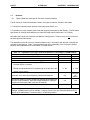
similar applications. They control devices that are connected via a network. Table 1.1 lists the Horner
Electric Conveyor Controller Modules.
Table 1.1 – Horner Electric Conveyor Modules
Horner Part Number
Description
HE400CCU310
Conveyor Control Unit with 0.5 Amp Outputs
HE400DNTx14
Micro PLC with Relay Outputs
HE400DNT188
Micro PLC with High Current Motor Outputs
PAGE 7
26 FEB 1999
1.3
Networks
1.3.1
Types of Networks Used with HE Conveyor Controller Modules
CHAPTER 1: INTRODUCTION
The HE Conveyor Controller Modules are used in two types of networks: CsCAN or DeviceNet.
a. CsCAN is a licensed network protocol created by Horner Electric, Inc.
b. DeviceNet is an open network protocol that was originally developed by Allen-Bradley. The DeviceNet
specification is currently administered by the Open DeviceNet Vendor Association, Inc. (ODVA).
DeviceNet and CsCAN use Controller Area Network (CAN) protocol. However, they can not co-exist on
the same physical CAN network.
The capabilities of the HE Conveyor Controller Modules vary in accordance with the type of network the
modules are designed for. Table 1.2 lists the differences in the capabilities of the Conveyor Controller
Modules when implemented into a DeviceNet or CsCAN network.
Table 1.2 – Capabilities of Conveyor Controller Modules in a DeviceNet or CsCAN Network
Capability
DeviceNet
CsCAN
Upload/Download Ladder Code over network.
No
Yes
Upload/Download firmware over network.
No
Yes
Ability to control the PLC and perform de-bugging.
No
Yes
a. Must directly upload/download programming into each
a. Yes
a. No
individual device on network.
b. Permits the upload/download of programming for all devices on the
network via one device.
Allows the use of slave devices made by various manufacturers.
Uses Horner Electric’s Cscape Software to configure and program the
Conveyor Control Modules. Also uses Cscape Software to configure,
program and download Ladder Code into the modules.
Provides for peer-to-peer communication
b. No
b. Yes
Yes
No-Uses
HE
Slaves.
Yes
Yes
*No
Yes
* To provide for peer-to-peer communications in a DeviceNet network, the “Unconnected Message
Manager” [UCMM] feature must be available. Currently, the HE Conveyor Controller Modules do not
support the UCMM method of communication in a DeviceNet network.
CHAPTER 1: INTRODUCTION
1.5
26 FEB 1999
PAGE 8
Additional DeviceNet Information
For more information on DeviceNet networks or the ODVA, visit the ODVA web site at www.odva.org.
1.6
Before Getting Started
a. Wiring diagrams, specifications, and other pertinent information for the HE Conveyor Controller
Modules are covered in individual data sheets created for each module.
PAGE 9
26 FEB 1999
NOTES
CHAPTER 1: INTRODUCTION
CHAPTER 2: DEVICENET
26 FEB 1999
PAGE 10
CHAPTER 2: DEVICENET IMPLEMENTATION
2.1
General
Chapter Two covers the features and requirements of HE Conveyor Controllers in a DeviceNet network.
2.1.1
DeviceNet Features Supported Using HE Conveyor Controller Modules
It is important to determine the features that the HE Conveyor Controller Modules support when used in a
DeviceNet network before programming, configuring, and setting up the network.
a. Communication Method
Although the DeviceNet Specification provides for two methods of communication, the HE Conveyor
Controller Modules implement only one of the methods, which is referred to as the “Predefined
Master/Slave Connection Set.” This method provides communications typically seen in a Master/Slave
relationship and uses a “DeviceNet Master/Slave” protocol.
The other method of communication is through the use of the “Unconnected Message Manager”
(UCMM). The HE Conveyor Controller Modules do not currently support the UCMM method of
communication.
b. Message Class / Message Priority
Both Explicit Messaging and I/O Connections are established using a message class known as
“Message Group 2 Only.” In this message class, the message priority is determined solely by the
network address of the individual nodes. The lower the node’s address, the higher its priority.
c. Types of Messages / Connections Supported
The “Explicit Messaging” and “Polled Connection” features are supported. The following terms are
defined per the DeviceNet Specification, Release (2.0), Volume I: DeviceNet Communication Model and
Protocol, Sections 1-4, 1-4.2., and 7-3.
Explicit Messaging: Used in typical request/response-oriented networks. Explicit Messages are used
to command the performance of a particular task and to report the results of
performing the task.
Polled Connection: Responsible for receiving the Master’s Poll Command and returning the associated
response.
“Explicit Messaging” is used for the transfer of small amounts of infrequently accessed data such
configurations or tuning.
The “Polled Connection” is used for data that is sent automatically between the slave and the DeviceNet
Master (Scanner) without intervention. The DeviceNet Master sends a “Polled Command” to a
DeviceNet Slave. The DeviceNet Slave produces or sends a “Polled Response” back to the DeviceNet
Master. (The “Polled Response” consists of 16 bits [2 bytes] of data.) All HE Conveyor Controllers
monitor (or “eavesdrop” on) “Polled Response” messages on the network. (See “Polled Snooping” in
Section 2.1.1,item d.)
PAGE 11
26 FEB 1999
CHAPTER 2: DEVICENET
The HE Conveyor Controller Modules do not support “Bit Strobed”, “Cyclic” and “Change-of-State”
connections.
d. Additional Feature available in HE Conveyor Controller Modules
A Horner Electric extension of the DeviceNet protocol known as “Polled Snooping” is also provided.
Polled Snooping is totally non-intrusive to DeviceNet traffic. The HE Conveyor Controllers monitor (or
“eavesdrop” on) all “Polled Response” messages on the network. The data in the “Polled Responses”
is used by the ladder code program in each of the HE Conveyor Controller Modules. Their ladder code
programs make decisions based on the “snooped” data. (See “Polled Connection” in Section 2.1.1,
item c.)
As “Polled Response” messages are received by other Conveyor Controllers, the first 16 bits (2 bytes)
of the response data are copied into their input map array indexed by the DeviceNet Node Address
(MACID) of the transmitting node. Through a process called “Mapping,” any 16 bits of data within the
Conveyor Controller Modules input map array can be selected to be copied into the %IG registers of the
respective Conveyor Controller. These 16 %IG registers can then participate in the ladder code running in
the HE Conveyor Controller Modules.
2.1.2
Configuration and Programming / Software Requirements
All configuration and ladder programming is performed through the use of Cscape Software. Cscape is
a 32-bit Windows program that runs on a Personal Computer (PC) using the Windows 95, Windows 98 or
Windows NT operating system. Cscape provides for a serial connection between the PC and the target
module. See the Cscape SoftwareUser Manual (GFK-1630) for more information regarding the features
and operation of Cscape.
Note:
It is not currently possible to perform ladder code updates, operating firmware updates or other
administration and control functions over a DeviceNet network. These function can only be
performed by a direct serial connection between a PC running Cscape and each individual front
panel serial port of the HE Conveyor Controller Modules.
2.1.3
Capabilities of HE Conveyor Controller Modules in a DeviceNet Network
The capabilities of the HE Conveyor Controller Modules vary in accordance with the type of network the
modules are designed for. The following list indicates the capabilities of the HE Conveyor Controller
Modules when implemented into a DeviceNet network.
a.
b.
c.
d.
e.
f.
g.
Allow the use of slave devices made by various manufacturers
Must have programming directly uploaded/downloaded into each individual device on network.
Must use Cscape Software to configure and program the Conveyor Control Modules. Must also
use Cscape Software to configure, program and download Ladder Code into the modules.
Can NOT upload/download Ladder Code or firmware over network
Can NOT control the PLC and perform de-bugging.
Can NOT permit the upload/download of programming for all devices on the
network via one device.
Can NOT provide for peer-to-peer communication
Note: To provide for peer-to-peer communications in a DeviceNet network, the “Unconnected
Message Manager” [UCMM] feature must be available. Currently, the HE Conveyor Controller
Modules do not support the UCMM method of communication in a DeviceNet network.
CHAPTER 2: DEVICENET
2.2
26 FEB 1999
PAGE 12
Requirements to Integrate HE Conveyor Controller Modules in a DeviceNet Network
The following requirements must be met to integrate HE Conveyor Controller Modules into a DeviceNet
network and to establish communications with a DeviceNet Master.
a.
DeviceNet Node Address (MACID)
In order to communicate with a DeviceNet Master, a unique MACID must be assigned to each node on
the network. Valid DeviceNet MACIDs are within the range of 0 - 63 inclusive (one DeviceNet Master and
63 Slave Nodes).
b.
DeviceNet Baud Rate
Each device connected to a DeviceNet network must be configured to operate at the same baud rate.
The baud rate for the HE Conveyor Controller Modules is fixed at 125K baud. Therefore, all other devices
on the network must also be configured to operate at 125K baud.
c.
Polled Input Data Assembly
The HE Conveyor Controller Modules “consume” (or expect to receive) 16 bits (2 bytes) of data whenever
a polled command is received. The 16 bits of data are stored in the Input Map array (at Index 64) in each
Conveyor Controller Module.
d.
Polled Output Data Assembly
After the poll command is received, the HE Conveyor Controller Modules “produce” (or send) 16 bits (2
bytes) of data to the DeviceNet Master as a response to a polled command.
PAGE 13
26 FEB 1999
NOTES
CHAPTER 2: DEVICENET
CHAPTER 3: SETUP/CONFIG.
26 FEB 1999
PAGE 14
CHAPTER 3: SETUP AND CONFIGURATION
3.1
Initial Procedures and Requirements
1.
Layout a DeviceNet scheme on paper and define I/O’s, node address references, etc.
It is important that the initial DeviceNet network be properly designed at the front-end of the project and
take in consideration any drops and nodes that will be added in the future. Haphazard additions of extra
"drops" and nodes at a later date often cause problems. Unterminated drops can be tolerated on a
DeviceNet network. Adding nodes later in the project can make configuration of the DeviceNet Master
(and its associated PLC) much more difficult and prone to human error.
2.
Configure the DeviceNet Master.
Consult the manufacturer’s user guide for procedures to configure the master.
The following items are required for communication between a DeviceNet Master and HE Conveyor
Controller Modules.
a.
DeviceNet Node Address (MACID)
In order to communicate with a DeviceNet Master, a unique MACID must be assigned to each node on
the network. Valid DeviceNet MACIDs are within the range of 0 - 63 inclusive (one DeviceNet Master and
63 Slave Nodes). To setup the MACID for the HE Conveyor Controllers, use a small screwdriver to
set the rotary encoder switch on the modules. Other slave devices on the network may need
different procedures. Consult the slave manufacturer’s user manual for procedures to set the MACID.
b.
DeviceNet Baud Rate (125Kbaud)
Each device connected to a DeviceNet network must be configured to operate at the same baud rate.
The baud rate for the HE Conveyor Controller Modules is fixed at 125Kbaud. Therefore, all other devices
on the network must also be configured to operate at 125Kbaud. Because HE Conveyor Controller
Modules are fixed at 125Kbaud, there is no action required by the user to set the baud rate.
However, other slave devices on the network may need different procedures. Consult the slave
manufacturer’s user manual for procedures.
PAGE 15
c.
26 FEB 1999
CHAPTER 3: SETUP/CONFIG.
Polled Input Data Assembly (Consumption Size)
The HE Conveyor Controller Modules “consume” (or expect to receive) 16 bits (2 bytes) of data whenever
a polled command is received. The 16 bits of data are stored in the Input Map Array (at Index 64) in each
Conveyor Controller Module. The process is called “Polled Snooping” and is described in 2.1.1 item d.
d.
Polled Output Data Assembly (Production Size)
After the poll command is received, the HE Conveyor Controller Modules “produce” (or send) 16 bits (2
bytes) of data to the DeviceNet Master as a response to a polled command.
3.2
Configuration Procedures
The following procedures are used to configure a HE Conveyor Controller Module for use in a DeviceNet
network. The configuration for the HE Conveyor Controller Module is accomplished using Cscape
Software. For the example configuration, the HE Conveyor Controller Module is a CCU310.
Note: Other slave devices on the network may require different configuration procedures. Consult the
slave manufacturer’s user manual for configuration procedures.
3.2.1
Selecting a Controller
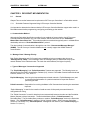
1. Go to the Main Screen and press Controller. Select Configure.
Press “Controller
and select “Configure.”
Figure 3.1 – Select Controller
CHAPTER 3: SETUP/CONFIG.
26 FEB 1999
PAGE 16
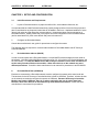
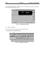
2. The following screen appears. The IC300OCS100 is shown as the selected controller. In this
configuration example, however, the desired controller is the HE400CCU310. Click the Config button
located next to the IC300OCS100 slot.
Figure 3.2 – Configure Controller Type Dialog
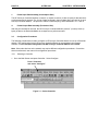
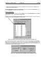
3. The following screen appears. Select the desired controller from the pull-down menu, and press OK.
Figure 3.3 – Selecting a Controller
PAGE 17
26 FEB 1999
CHAPTER 3: SETUP/CONFIG.
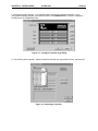
4. The following screen appears. The desired controller is now selected. Press the X in the upper-right
corner of the Configure I/O screen to close.
Figure 3.4 – HE400CCU310 Selected
3.2.2
Network Configuration
5. From the Main Screen, press Program and select “Network Config.”
Press Program. Select “Network Config.”
Figure 3.5 – HE400CCU310 Selected
CHAPTER 3: SETUP/CONFIG.
26 FEB 1999
PAGE 18
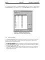
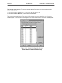
6. The following screen appears.
a. The Point node is the HE Conveyor Controller that is being configured.
b. The Source node represents a different HE Conveyor Controller on the network than the Point node.
c. The Net ID address is that of the Source node.
Configuring this screen allows the Point node to receive data from:
a. Various Source nodes’ %QG registers and to have the data sent to the Point node’s %IG
registers. (See Steps #6 through #8.)
b. The DeviceNet Master (using a special index address of “64”) and to have the data sent to the Point
node’s %IG registers. (See Steps #9 through #11.)
Example Configuration: This example depicts a Point node receiving data from a Source Node
(Refer to Figure 3.12.)
In this example configuration, the user wants the %QG8 data from a Source node (with a Net ID of 5) to
be sent to the Point node’s %IG2 register.
Note: An example of a Point node receiving data from a DeviceNet Master is illustrated later in Step #9.
To edit the screen and select the appropriate %IG and %QG registers and Net ID, use the mouse arrow
and double-click on the desired Point node’s %IG2 register.
1. The user needs
to edit this screen to
achieve the following
transfer of data:
The user wants the
%QG8 register data
from the Source
node to be sent to
the Point node’s
%IG2 register.
Network ID: Represents
the node address of the
Source node, which is a
different HE Conveyor
Controller on the network
than the Point.
The user wants to edit
this screen so that the
Source node’s %QG8 data
is sent to the Point node’s
%IG2 register.
The Source node
has a Net ID
address of 5.
Figure 3.6 – Network Configuration Screen (Before Configuration Parameters are Set)
PAGE 19
26 FEB 1999
CHAPTER 3: SETUP/CONFIG.
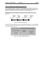
7. The following screen appears. Using pull-down menus, select the node address of the Source and
the %QG.register from which the data is to be obtained. In this example, the data is to be obtained
from a Conveyor Controller (Souce) with a Net ID of 5, and the information is to be obtained from
%QG8 within the Source. Press OK.
Figure 3.7 – Network I/O Input Assignment Screen
8. The following screen indicates that the Source node’s %QG8 data is to be sent to the Point node’s
%IG2 register. The Source node’s Net ID is 5.
Figure 3.8 – Network Configuration Screen
(Shows Status of Example Configuration%IG2)
CHAPTER 3: SETUP/CONFIG.
26 FEB 1999
PAGE 20
9. Steps #6 through #8 illustrated an example of the Point node receiving data from a Source Node
(HE Conveyor Controller Module).
The following example illustrates how the Point node receives data from the DeviceNet Master. The
DeviceNet Master uses special index address of “64.”
Example Configuration:
In this example configuration, the user wants the %QG1 data from a DeviceNet Master (with a special
Net ID of 64) to be sent to the Point node’s %IG1 register.
To edit the screen and select the appropriate %IG and %QG registers and Net ID, use the mouse arrow
and double-click on the desired Point node’s %IG1 register.
Figure 3.9 – Network Configuration Screen (Before Parameters have been set.)
10. The following screen appears. Using pull-down menus, select the node address of the DeviceNet
Master and the %QG.register from which the data is to be obtained. In this example, the data is to be
obtained from a DeviceNet Master (Source) with a special Net ID of 64 , and the information is to
be obtained from %QG1 within the Source. Press OK.
Figure 3.10 – Selecting the DeviceNet Master’s Special Address of “64.”
PAGE 21
26 FEB 1999
CHAPTER 3: SETUP/CONFIG.
11. The following screen appears. It indicates that the Point node’s %IG1 register is to receive data from
the DeviceNet Master’s %QG1 register (Source). The DeviceNet Master has a special Net ID of “64.”
Figure 3.11 – Network Configuration Screen
(Shows Status of Example Configuration%IG1)
3.2.3
Relative ID Addressing
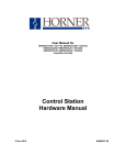
9. The Relative ID Addressing feature simplifies the configuration process involving a number of HE
Conveyor Controller Modules that are located on different conveyor segments. If each Conveyor
Controller is going to be configured such that:
a. The same %IG registers are going to be configured in each Point node to store specific data sent
from the Source nodes AND
b. The same %GQ registers of the Source nodes are going to be configured to send specific data to
the Point node’s %IG registers, THEN
c. The Relative ID Addressing feature allows a single ladder file (which includes logic, configuration,
and the network map) to be used by a number of conveyor controllers on the network, which are
performing the same functions.
CHAPTER 3: SETUP/CONFIG.
26 FEB 1999
PAGE 22
Example: Configuration using Relative ID Addressing Feature
In this configuration example , the Relative ID Addressing feature is selected. In Figure 3.9, the
user wants the Point node to be configured such that the Source nodes (on conveyor segments located
just before and after the Point node) send the data from the same %QG registers to the same %IG
registers as in the Point node. (The process is described in more detail in Section 3.2.2.)
Note that Source -1 is one Net ID address lower than the Point’s Net ID address. Also note that
Source+1 and Source +2 Net ID addresses are greater than the Point’s Net ID address by 1 and 2
respectively.
Source –1
Net ID: 3
CCU310
Point
Net ID: 4
CCU310
Segment 1
Segment 2
Source +1
Net ID: 5
CCU310
Source +2
Net ID: 6
CCU310
Segment 3
Figure 3.12 – Example Conveyor Line
In Figure 3.10, the user has clicked on the box to select “Relative ID Addressing.” The user has typed in
“-1” for the Remote Network ID. This means that the Net ID of the Source is relative to the Point’s Net ID
by an offset of minus one. Press OK.
Figure 3.13 – Network Configuration Screen
PAGE 23
26 FEB 1999
CHAPTER 3: SETUP/CONFIG.
The following screen appears. The screen indicates that the Point node is to receive data from two
Source nodes that are:
a. One Net ID address greater than (+1) the Point’s Net ID address, and
b. One Net ID address less than (-1) the Point’s Net ID address.
The screen also depicts that the Point node’s %IG1 register is to receive data from the +1 Source’s
%QG6 register. The Point node’s %IG2 register is to receive data from the -1 Source’s %QG8 register.
Figure 3.13 – Network Configuration Screen
(Shows Status of Relative ID Addressing)
CHAPTER 4: OPERATION
26 FEB 1999
PAGE 24
CHAPTER 4: OPERATION
4.1
DeviceNet Overview
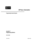
Chapter Four describes an example DeviceNet network using HE Conveyor Controller Modules
(CCU310) in a conveyor application. Refer to Figure 4.1.
1. The DeviceNet Network allows a DeviceNet Master to communicate with slave nodes over a
common bus. Figure 4.1 depicts a DeviceNet network using CCU310 devices. Conveyors are typically
laid out in segments. Each segment typically uses a HE Conveyor Controller (i.e., CCU310) to control a
specific segment and to communicate with HE Conveyor Controllers located on other segments of the
conveyor. The CCU310 also communicates with the DeviceNet Master. A total of 64 nodes is available
on the network including the DeviceNet master. Up to 63 slave devices can be used.
In the example configuration, two segments of a conveyor operation are shown. Each segment has a HE
Conveyor Controller Module (CCU310) and one other slave device connected to it.
Conveyor Segment 2
Conveyor Segment 1
2. DeviceNet Master
1. Device Net
3. CCU310
OCS100
CCU310
4. Slave Device
Up to 63 slave devices can be
used. (There are 64 Total Nodes
Including the DeviceNet Master.)
5. If configuration or
programming is required
for any device on the
network: The user must
directly upload/download
programming into each
individual device.
(Can be a slave device made by
various manufacturers.)
Figure 4.1 – Using HE Conveyor Controller Modules
in a DeviceNet Network
PAGE 25
26 FEB 1999
CHAPTER 4: OPERATION
2. The DeviceNet Master sends two types of messages to the slaves. The first message is an Explicit
Message, which is used for the transfer of small amounts of infrequently accessed data such as
configuration or tuning. The second type of message is a Polled Connection. It is used for data that is
sent automatically between the slave and the DeviceNet Master (Scanner) without intervention. When
the slave responds with a “Polled Response,” all of the HE Conveyor Controller Modules “snoop” the data
as described in item 3.
3. The DeviceNet Master sends data to the HE Conveyor Controllers (“Polled Commands”) and
receives data from the HE Conveyor Controllers (“Polled Responses”). Using a feature called “Polled
Snooping,” all HE Conveyor Controllers (i.e., CCU310) monitor (or “eavesdrop” on) the “Polled
Response” messages on the network. “Polled Snooping” is non-intrusive to DeviceNet traffic
The data in the “Polled Responses” can be used by the ladder code program in each of the HE Conveyor
Controller Modules (i.e., CCU310). The individual ladder code programs of the HE Conveyor Controllers
can then make decisions based on the “snooped” data.
Each of these processes are described as follows:
DeviceNet Master sends data to a HE Conveyor Controller, and the HE Conveyor Controller
responds; The other HE Conveyor Controllers in the network “snoop” the data, which is sent into
their %IG registers via “Mapping”:
a.
The DeviceNet Master sends a “Polled Command” to up to 63 DeviceNet Slaves on the network.
Each of the Slaves that were sent the “Polled Command” produces or sends a “Polled Response” back to
the DeviceNet Master. (The “Polled Response” consists of 16 bits [2 bytes] of data.). All other HE
Conveyor Controllers (i.e., CCU310) snoop (or “eavesdrop” on) all “Polled Response” messages on the
network.
b.
The “Polled Command” data that is send from the DeviceNet Master to specific HE Conveyor
Controllers is sent to a special address or “storage location” in the individual HE Conveyor Controller’s
Input Map Array at Index 64. The Input Map Array has sixty-five addresses or “storage locations” (0-64).
There is an address for each of the 64 nodes on the network.
c.
As “Polled Response” messages are received by the other HE Conveyor Controllers, the first 16
bits (2 bytes) of the response data are copied into each of the Conveyor Controller’s Input Map Array.
d.
Through a process called “Mapping,” any 16 bits of data within each Controller’s Input Map
Array can be selected to be copied into its %IG registers. (The user determines the selection of the 16
bits via the configuration process.) These 16 %IG registers can then participate in the ladder code
running in the HE Conveyor Controller Modules. “Mapping” occurs at the start of every scan.
The Ladder Code sends data to the DeviceNet Master via a “Polled Response” message;
Other HE Conveyor Controllers “snoop” which is sent to their Input Map Arrays:
a.
Depending upon how its written, the ladder code can respond to the “Polled Responses received
by the HE Conveyor Controller Modules. By sending “global data” (%QG) to the DeviceNet Master, this
output data is “snooped” by all HE Conveyor Controllers on the network and is placed into their Input
Map Arrays. For example, if one segment of the conveyor stops momentarily, the ladder code can be
written such that the rest of the conveyor line is “notified” and can respond appropriately. The user can
configure the HE Conveyor Controller Modules to receive the data in the %QG registers of other HE
Conveyor Controller Modules or the DeviceNet Master.
For a step-by-step explanation on how to configure the HE Conveyor Controller Modules (i.e.,CCU310)
and to use a feature known as Relative ID Addressing, refer to Sections 3.2.2 and 3.2.3 in Chapter 3.
CHAPTER 4: OPERATION
26 FEB 1999
PAGE 26
4. Up to 63 DeviceNet Slaves can be used in the network. There are 64 total nodes including the
DeviceNet Master. The slaves can be made by various manufacturers. In order to communicate with a
DeviceNet Master, a unique DeviceNet Node Address (MACID) must be assigned to each node on the
network. . HE Conveyor Controller Modules (i.e., CCU310) have a fixed baud rate of 125Kbaud. Thus,
all nodes on the network must be set at the same baud rate of 125Kbaud.
5. To install upgrades or perform configuration, the user must directly upload/download programming
into each individual device.