1
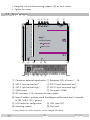
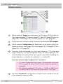
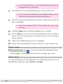
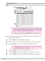
Head-end Station
GSS.compact
STC 4-16
KLASSE
Default access data:
192.168.0.120
User: admin
Password: geheim
English
CLASS
GSS
Grundig SAT Systems GmbH
Beuthener Strasse 43
D-90471 Nuremberg
Phone:
Fax:
E-mail:
Internet:
+49 (0) 911 / 703 8877
+49 (0) 911 / 703 9210
[email protected]
http://www.gss.de/en
Contents
1 Safety regulations and notes......................................................................... 3
2 General information..................................................................................... 5
2.1 Packing contents.............................................................................5
2.2 Meaning of the symbols used...........................................................5
2.3 Technical data................................................................................5
2.4 Description....................................................................................7
Block diagram................................................................................7
General.........................................................................................7
3 Assembly..................................................................................................... 8
3.1 Installing the device........................................................................8
3.2 Device overview.............................................................................9
3.3 Potential equalisation (PE)..............................................................10
3.4 Connecting the device...................................................................10
4 Configuration / Updates............................................................................. 11
4.1 Initial configuration.......................................................................11
4.2 Configuration...............................................................................14
Overview window........................................................................14
Perform changes..........................................................................15
Number format............................................................................15
Configuration menus.....................................................................16
Input......................................................................................16
Output...................................................................................18
NIT........................................................................................20
Filter......................................................................................23
LCN – Logical Channel Numbering...........................................25
System menus..............................................................................27
Logbook.................................................................................27
Network.................................................................................27
OpenVPN..............................................................................28
Security..................................................................................29
E-Mail....................................................................................30
Firmware................................................................................31
- System settings:.....................................................................31
- Firmware update:..................................................................32
- Backup:................................................................................33
- Reset to factory defaults:.........................................................33
- System restart:.......................................................................33
User.......................................................................................33
5 Channel and frequency tables..................................................................... 34
- 2 -
STC 4-16
1
Safety
regulations and notes
• The devices meet the EU directives 2006/95/EC, 2004/108/EC and
2011/65/EU.
• This device is subject to the provisions of protection class I. Operate the
device only to mains sockets with protective conductor connection!
• If the power cord needs to be replaced, only use an OEM power cord.
• The standards EN/DIN EN 50083 resp. IEC/EN/DIN EN 60728 must be
observed, especially concerning equipotential bonding and earthing.
• Observe the relevant country-specific standards, regulations and guidelines
on the installation and operation of antenna systems.
• Before starting installation or service work disconnect the receiving system
from mains.
• Do not perform installation and service work during thunderstorms.
• Assembly, installation and servicing must be carried out by an authorised
electrician.
• For a complete disconnection from the mains, the mains plug must be pulled
out of the mains socket. Ensure that the mains plug can be pulled out without
difficulties.
• The head-end station should only be installed in a room where the permissible ambient temperature range (0 °C … +50 °C ) can be maintained, even
during fluctuations in climatic conditions.
• Make sure there is a minimum space of 10 cm on either side and 50 cm
above and below.
• To avoid too strong interacted heating of the head-end stations it is not
admissible to mount them one upon the other without using thermic precautions (e.g. permanently air recirculation, ventilation, heat deflectors etc.).
• If additional fans are to be used to circulate the air, ensure that the system
will be shut down (disconnected from mains) should any one of the fans fail.
• Install the head-end station
- in a dry, dust-free environment, in such a manner that it is protected from
moisture, fumes, splashing water and dampness
- where it is protected from direct exposure to sunlight
- on a vibration-free wall or floor construction
- not within the immediate vicinity of heat sources
• In case of the formation of condensation wait until the system is completely
dried.
• Ensure that the head-end station is adequately ventilated.
• Do not cover the ventilation openings!
• Do not install the head end in cabinets or recesses which are not ventilated.
- 3 -
STC 4-16
• Do not place any vessels containing liquids on the head-end station.
• Do not place anything on the head-end station which could initiate fires
(e.g. candles).
• Due to the risk of fires caused by lightning strikes, we recommend that
all mechanical parts (e.g. distributor, equipotential bonding rail, etc.) be
mounted on a non-combustible base. Wood panelling, wooden beams,
plastic covered panels and plastic panels are all examples of combustible
bases.
• Avoid short circuits!
• To ensure electromagnetic compatibility, make sure all connections are tight
and that the covers are screwed on securely.
• No liability is accepted for damage caused by faulty connections or inappropriate handling of the device.
• The firmware contains components which are licensed as Open Source
software. The components to which this relates and the respective license
terms can be called up via menu Help/Licences.
This parts of software source code can be provided at cost price on CD
upon request. The licensee is granted a non-exclusive right of use for the
Open Source Software by the respective right holders used; the conditions
stipulated by the respective valid license terms apply. The license terms of
this license only apply to the components which are not listed as Open
Source software.
In relation to the licensor the regulations on liability and warranty in these
license terms apply for the whole software. The liability and warranty regulations of the Open Source licenses only apply in relation to the respective
right holders.
• Test the firmware versions of the device and update them if necessary. The
current firmware version can be found at "www.gss.de/en".
Take action to prevent static discharge when working on the device!
Electronic devices should never be disposed of in the household rubbish. In accordance
with directive 2002/96/EC of the European Parliament and the European Council from
January 27, 2003 which addresses old electronic and electrical devices, such devices
must be disposed of at a designated collection facility. At the end of its service life,
please take your device to one of these public collection facilities for proper disposal.
- 4 -
STC 4-16
2
General
2.1 Pac k i n g
information
contents
1 STC 4-16
1 LAN cable
1 Brief assembly instructions
1 Mains cable
1 Supplementary sheet station allocation
2.2 M e a n i n g
o f t h e s ym b o l s u s e d
Important note
Danger by electrical shock
—>
General note
•
Performing works
2.3 T e c h n i c a l
data
The devices meet the following EU directives:
2006/95/EC, 2004/108/EC, 2011/65/EU
The product fulfils the guidelines and standards for CE labelling (page 35).
Unless otherwise noted all values are specified as "typical".
RF input DVB-S/S2 (ETSI 300 421)
Frequency range:........................................................ 950 … 2150 MHz
DVB-S modes:................................................................................ QPSK
DVB-S2 modes:......................................... QPSK, 8PSK, 16APSK, 32APSK
Symbol rate DVB-S:............................................. QPSK: 1 … 45 MSymb/s
Symbol rate DVB-S2:
QPSK.................................................................... 4.5 … 45 MSymb/s
8PSK..................................................................... 4.5 … 45 MSymb/s
16APSK................................................................. 4.5 … 39 MSymb/s
32APSK................................................................. 4.5 … 32 MSymb/s
Maximum data rate/tuner.......................................................... 83 MBit/s
Level range:............................................................. 60 dBμV … 80 dBμV
Input impedance:............................................................................. 75 Ω
LNC 12V supply:.................................................................max. 300 mA
- 5 -
STC 4-16
RF output
Frequency range:.............................................. 42.0 MHz … 868.0 MHz
Channels:............................................................................. S21 … C69
Types of modulation:...................................QAM 4, 16, 32, 64, 128, 256
Dynamic phase error:..................................................................... < 0.2°
MER:.............................................................................................45 dB
Symbol rate.................................................................. 1000…7500 kBd
Output level:....................................................................... 80…96 dBμV
Output impedance:.......................................................................... 75 Ω
LAN interface for HTML control/update
Standard:............................................................................ 1000-BASE-T
Connections
SAT inputs:.............................................................................. 4 F sockets
RF output:............................................................................... 1 F socket
RF test output (-25 dB):............................................................. 1 F socket
LAN:................................................................................. 1 RJ 45 socket
General
Mains voltage:................................................... 220…240V~, 50/60 Hz
Power consumption without LNC supply............................................ 40 W
Maximum Power consumption:......................................................... 55 W
Admissible ambient temperature:.............................................0 … +50 °C
Dimensions (WxHxD):................................................ 341 x 282 x 85 mm
Weight:........................................................................................... 5 kg
- 6 -
STC 4-16
2.4 D e s c r i p t i o n
The head-end station converts 16 transponders modulated acc. to DVB-S/
DVB-S2 standard (up to 32 APSK) into 16 DVB-C modulated transponders.
B lo c k
d i ag r a m
SAT IN 1
SAT IN 2
Tuner "1"
TPS
Modulator
"1"
Tuner "2"
TPS
Modulator
"2"
Tuner "3"
TPS
Modulator
"3"
SAT IN 3
SAT IN 4
Combiner
RF OUT
–25dB
Tuner "16"
TPS
Modulator
"16"
TEST
General
The station is equipped with four SAT IF inputs, one RF output and one test output (–25 dB). It is preset to receive the most popular ASTRA transponders (see
supplementary sheet). Different programming is possible at any time. Each of
the 16 tuners can be assigned to any SAT input. Via the RF output of the station, the QAM modulated RF output signals are output. The output levels of the
channel strips can be set.
The configuration of the station is to be done via an HTML user interface via a
PC and a standard HTML browser connected to the LAN input.
After the initial setup, you have
worldwide access to the station via
an OpenVPN connection – by PC,
tablet or smart phone with Internet
access.
GSS
OpenVPN
Server
—> When using mobile terminals – dependent on your mobile contract
– additional connection costs / data transfer costs may also be
incurred here.
- 7 -
STC 4-16
16 LEDs provide an indication of the SAT IF input signal quality based on their
colour and indicate if the respective channel strip is switched on (LED illuminates) or off. If there is an overflow of the output data rate, the corresponding
LED blinks.
3
Assembly
3.1 I n s ta l l i n g
the device
– The device must not be operated lying down, since the function of the heat
sink will be severely restricted. Only with vertically arranged cooling fins
sufficient cooling is ensured.
– The device should only be installed in a room where the permissible ambient temperature range (0 °C … +50 °C ) can be maintained, even during
fluctuations in climatic conditions.
– Mount the device on a non-combustible base.
– Use mounting material suitable for the wall properties.
– Position the device with a minimum distance on the left and right side of 10
cm, below and above 50 cm.
• Attach four mounting screws at the installation site. The drilling distances
are shown in the drawing below.
#
218 mm
#
320 mm
- 8 -
STC 4-16
• Hang the unit with the mounting supports
• Tighten the screws.
3.2 D e v i c e
# on the 4 screws.
ov e rv i e w
1
2
3456
7
8
1
2
3
4
5
6
7
8
9
10
11
12
13
14
15
16
#
9
0
! @
#
9
0 $ ! @
1 Connector potential equalisation2 Reception LEDs of tuners 1…16
3 SAT IF input vertical low*
4 SAT IF input horizontal low*
5 SAT IF input vertical high*
6 SAT IF input horizontal high*
7 QAM output
8 Test output –25dB
9 IEC connector C14; connector for mains cable
0 Reset IP address and password (hold depressed for more than 5 seconds)
to 192.168.0.120 / geheim
! LAN socket for configuration
# Mounting support
* Factory defaults for ASTRA reception, can be changed individually.
@ LAN status LED
$ Not used
- 9 -
STC 4-16
3.3 P ot e n t i a l
e q ua l i sat i o n
(PE)
Equalise the potential (PE) in accordance with IEC/EN/DIN EN 60728.
• Connect the PE connection terminal 1 to a PE rail (supplied by customer)
using the PE wire (Cu 4 mm2 - 9 mm2).
3.4 C o n n e c t i n g
the device
• Connect the SAT IF inputs…
3 vertical low*
4 horizontal low*
5 vertical high*
6 horizontal high*
… to the corresponding outputs of an LNB.
*Factory defaults for the preprogrammed ASTRA reception, can be changed
individually.
• Connect the attached mains cable to the IEC connector C14
9.
—> If you would like to integrate the device to an existing plant, now
first you should connect it to the mains and perform all settings (Configuration page 11).
• Connect the mains cable to a mains socket with protective conductor connection. Thereby note the voltage specified on the device.
—> This device has no power switch and starts immediately after connecting the operating voltage.
• Configure the device (page 11).
• If the programming is finished connect the RF output
work.
- 10 -
7 to the cable net-
STC 4-16
4
C o n f i g u r a t i o n / U p d a t e s
The configuration of the station is to be done via an HTML user interface via a
PC and a standard HTML browser.
4.1 I n i t i a l
c o n f i g u r at i o n
• Connect a PC via a LAN cable directly to the LAN input
!.
—> The PC and the head-end station must be within the same network
(same IP address range). Cookies must be accepted an JavaScript
must be active.
—> Example for IP address setting with Windows 7 operating system:
• For the initial setup open the properties for TCP/IPv4 of the PC:
> Control Panel
> Network and Sharing Center
> LAN connection
> Properties
- 11 -
STC 4-16
> Internet Protocol Version 4 (TCP/IPv4)
> Properties
•
•
•
•
Activate point "Use the following IP address".
Enter e.g. 192.168.0.2 for the IP address.
Enter for the Subnet mask 255.255.255.0.
Confirm the setting with "OK".
- 12 -
STC 4-16
• Start the browser, enter the IP address of the device (factory default is
192.168.0.120) and start the establishment of the connection.
• Enter user "admin" and your Password and click on button "Login".
The default password is "geheim".
—> For further logins observe the menus System > Network and System
> OpenVPN!
—> The Overview window is displayed.
First, an "empty" table is displayed (as with all menus). While the
data is read from the device ...
… is displayed.
- 13 -
STC 4-16
4.2 C o n f i g u r at i o n
O v e rv i e w
w i n d ow
20
25
21
26
22
27
28
29
23
24
30
20 Via the selection System you have access to the menus of the System settings: Logbook (page 27); Network (page 27); OpenVPN (page 28); Security
(page 29); E-Mail (page 30); Firmware (page 31); User (page 33)
21 In all menus you will return to the Overview via the button GSS.compact.
22 Via the selection Configuration you have access to the menus of the Configuration settings: Input (page 16); Output (page 18); NIT (page 20); Filter
(page 23); LCN (page 25)
23 Overview of the transponder set, with input frequency, C/N value and
output frequency. Via the background colour of column Line you are
informed about the quality of the input signals, a possible exceeding the
output data rate, or whether the modulator is switched off.
—> If in menu Configuration/Input (page 16) transponder names are
NOT assigned, the name of the first station of each transponder is
displayed.
—> The maximum displayed C/N value is 15.0dB at DVB-S resp.
20.0dB at DVB-S2. This means the actual value is ≥15/20dB.
24 Via button Download a configuration protocol can be stored as text file
resp. opened using a text editor.
- 14 -
STC 4-16
—> From this protocol file e.g. a list of the programmed stations can be
prepared using e.g. a text editor.
25 This location text can be modified arbitrary in menu System/User.
—> If you remote control head-end station at different locations, herein
you can enter the location and a local contact person.
26 Herein the current system temperature as well as date and time of the last
login is displayed.
—> If a system temperature of 85°C will be reached, the system will be
shut down..
27 Via button Logout you can leave the graphical user interface.
28 Via the Help menu you can call up the assembling instructions (PDF) as
well as a ZIP file containing a list and all licences of the used OpenSource software.
29 Herein the installed firmware version is displayed.
30 Herein notes are displayed, which you can enter in menu System/User.
Perform
c h a n g es
Before leaving a menu, changes must be transmitted to the head-end station.
• Therefore click on button
.
After that
is displayed for a short time in the upper right corner.
Number
For entering/indication of the different IDs the number format can be set to
hexadecimal or decimal in menu System > Firmware.
f o r m at
- 15 -
STC 4-16
C o n f i g u r at i o n
Input
menus
31
33
34
32
35 36 37 38 39
40
—> Via the background colour of column Line you are informed about
the quality of the input signals, a possible exceeding the output data
rate, or whether the modulator is switched off.
31 In column fLNB, enter the LNB Oscillator frequencies for the 4 inputs – dependent on the LNB used.
32 In column Name, enter a personal input name.
33 With this button switch on or off the LNB supply (12V/max. 300mA).
34 In column Name, you can enter a personal transponder name
—> If transponder names are NOT assigned, the name of the first station of each transponder is displayed.
35 In column Input, select the desired input for each tuner.
36 In column f (MHz), enter the desired input frequency for each tuner.
37 In column SR (kS/s), enter the related input symbol rate for each tuner.
- 16 -
STC 4-16
38 In column foffset, the current frequency offset is displayed.
—> The frequency offset should not exceed ± 1.5 MHz!
IF necessary correct the LNB oscillator frequency (if all transponders of one input are affected) resp. the input frequency (if only one
transponder is affected) accordingly.
39 In this column, the C/N is displayed with reserve.
—> The maximum displayed C/N value is 15.0dB at DVB-S resp.
20.0dB at DVB-S2. This means the actual value is ≥15/20dB.
40 Before leaving the menu, changes must be transferred to the head-end
station!
• Therefore click on button
.
—> After that
is displayed for a short time in the upper right corner.
- 17 -
STC 4-16
Output
41 42
48
43 44 45 46
47
—> Via the background colour of column Line you are informed about
the quality of the input signals, a possible exceeding the output data
rate, or whether the modulator is switched off.
41 In column Output, switch on or off the modulators of the individual lines.
42 In column Chan. / Freq. [MHz], enter the desired output channel/frequency of the individual lines.
—> Double assignments are indicated by a
warning icon
.
—> The QAM signal is normally transmitted with a bandwidth of 8 MHz. This
means that you can only use the channel centre frequency of the existing channel grid in the range of
channels C21…C69 (frequency grid 8 MHz). The CCIR channel
grid is 7 MHz in the range of the lower frequency bands (channels
C5 … C12). If 8 MHz QAM signal packages are transmitted in
these channel ranges, this will result in interference (overlapping)
and transmission problems.
- 18 -
STC 4-16
43 For programming in these channel ranges and in the frequency ranges below them, we recommend starting with frequency 306 MHz
going back in steps of 8 MHz (see frequency table on page 34).
Please note thereby that many receivers cannot receive the channel
ranges S21 … S41 (306 … 466 MHz).
In column SR [kS/s], enter the desired output symbol rate of the individual
lines.
—> The background colour
in column Line indicates an output data
overflow.
In this case increase the output symbol rate or the QAM modulation
or remove stations from the data stream using the station filter.
44 In column Modulation, select the desired kind of modulation of the individual lines.
—> The background colour
in column Line indicates an output data
overflow.
In this case increase the output symbol rate or the QAM modulation
or remove stations from the data stream using the station filter.
45 For exceptional cases and "older" digital cable receivers, in column
Spectrum the spectral position of the user signal can be inverted (invers).
Factory default is "normal".
46 In column Level [dB], balance the output levels of the different lines
(0…-10dB).
Therefore measure and note down the output level of each modulator.
Adjust the higher output levels to the output level of the modulator with
the lowest output level incrementally.
—> Changes must be transmitted to the head-end station!
Therefore click on button
.
47 Balance here the master output level of the station to the level of the cable
network.
—> Changes must be transmitted to the head-end station!
Therefore click on button
.
- 19 -
STC 4-16
48 Before leaving the menu, changes must be transferred to the head-end
station!
• Therefore click on button
.
—> After that
is displayed for a short time in the upper right corner.
NIT
51
52
54
53
55
56
57
51 62 58 59 60 61
Herein you can change the Network ID.
—> For entering/indication of the different IDs the number format can
be set to hexadecimal or decimal in menu System > Firmware.
52 Herein you can enter a NIT version.
—> The maximum possible value is 1F/31.
53 Herein you can enter a network name.
54 Button Load resets the network ID, the version and the network name to
default.
55 Herein you get an overview of the transponders, which are included in
the NIT. If changes are done in menu output after preparing the NIT, this
is indicated in column Line by a "–" and in column Options the button
for Edit
and Delete
are displayed.
- 20 -
STC 4-16
Now you can delete
or edit
the faulty entry.
—> If you delete a faulty entry, all related LCNs will also be deleted.
—> If you did NOT manually added or imported transponders, you can
also easily generate only a new NIT 56 .
56 Create the NIT
—> If you had transponders manually added or imported, they will be
deleted.
57 Herein you can add a prior exported NIT (restore a backup) or e.g. the
NIT of a second station.
—> The data is added - NOT replaced!
Restore a backup:
• First delete the NIT ( 58 ).
• Click on button Upload 57 and select the backup file (*.bin).
• In the selection window click on button "Open".
The data is added.
• Click on button
.
Add the NIT of a second station:
• Click on button Upload 57 and select the backup file (*.bin).
• In the selection window click on button "Open".
- 21 -
STC 4-16
The data is added.
• Click on button
.
—> Added transponders of a second station are marked in column Line
by a "–".
—> If you use LCNs, you subsequently must add the "*.bin" file in menu
Configuration > LCN 91 (page 25), so that also the service names are
indicated.
—> Now finally you must export the revised NIT. Then load this file into
the second station like a backup.
Now both stations have identical NITs.
58 Herein you can delete the NIT as well as the LCNs.
—> Switch off the NIT:
Delete the NIT.
Thus, no NIT is played out on the station!
59 Herein you can manually add QAM transponders of
other stations.
—> Double assignments are indicated by a warning
icon
.
—> Added transponders of a second station are marked in column Line
by a "–".
—> For entering/indication of the different IDs the number format can
be set to hexadecimal or decimal in menu System > Firmware.
60 Herein you can manually add COFDM transponders of
other stations.
—> Double assignments are indicated by a warning
icon
.
—> Added transponders of a second station are marked in column Line
by a "–".
- 22 -
STC 4-16
—> For entering/indication of the different IDs the number format can
be set to hexadecimal or decimal in menu System > Firmware.
61 Herein you can export the NIT for backup or e.g. in order to add the NIT
to a second station.
—> The exported file contains the NIT as well as the LCNs.
62 Before leaving the menu, changes must be transferred to the head-end
station!
• Therefore click on button
.
—> After that
is displayed for a short time in the upper right corner.
F i lt e r
71
72
73
74
75
76
79
77 78
In menu Filter you can remove stations (Services) and PIDs (Drop PIDs) from the
data streams of the transponders (with adaptation of the tables).
71 Select between displaying the station filter …
72 … or displaying the PID filter.
—> For entering/indication of the different IDs the number format can
be set to hexadecimal or decimal in menu System > Firmware.
- 23 -
STC 4-16
73 Herein you can select whether only one line is displayed or all lines are
displayed.
74 In column Filter you can individually switch on or off the filter.
75 In column Pass Service you select the stations (services) which you would
like to play out.
—> Only if the filter 74 is enabled, services in which the hook has been
removed, are suppressed (filtered out)!
—> The background colour
in column Line indicates an output data
overflow. In this case increase the output symbol rate, change the
QAM modulation or remove individual stations from the data stream
using the station filter.
76 Via button Reset, only for the displayed filters (dependent on the selections for Typ 71 72 and Overview 73 ) column Pass Service is reset to
factory defaults.
—> All hooks are set.
77 Activate the indication of the PID filter by select box "Drop PIDs" 72 .
Herein you can remove individual PIDs from the transport stream of each
line.
• Enter the PID to be dropped...
78 ... and confirm with "+".
—> After that an additional field appears to enter an additional PID.
—> Therefore also observe the functions 73 and 76 .
79 Before leaving the menu, changes must be transferred to the head-end
station!
• Therefore click on button
.
—> After that
is displayed for a short time in the upper right corner.
- 24 -
STC 4-16
LCN – L o g i c a l C h a n n e l N u m b e r i n g
81
82
83
84
86
85
90
91
87
88
89
—> Before you can assign LCNs, a NIT must be created or imported.
—> Due to the differentiation of SD LCN and HD LCN it is possible to
assign the same channel number for a channel transmitted in "SD"
and "HD" quality. Suited "HD" receivers will prefer the services in
"HD" quality, "SD" receivers will use the service in "SD" quality.
81 Herein enter the LCNs for "SD" receiving devices.
82 Herein enter the LCNs for "HD" receiving devices (also SD channels).
—> Ensure that the receiving devices support HD LCN error-free. Otherwise we recommend to use exclusively SD LCNs.
83 Herein you can switch on or off the "Private Data Specifier".s
—> If you use HD-LCN, this must be switched on.
84 "Private Data Specifier" value
—> For "Private Data Specifier" IEC 62216-1 recommends the value
HEX 00000028. Receivers in German speaking regions mainly
use this setting. As in some regions (e.g. United Kingdom, Nordig,
France etc.) different regulations exist, observe the country specific
guidelines, if required.
- 25 -
STC 4-16
85 Bits for LCN data structure
—> For "LCN Data Structure" IEC 62216-1 recommends the value
"10 Bit". Receivers in German speaking regions mainly use this setting. As in some regions (e.g. United Kingdom, Nordig, France etc.)
different regulations exist, observe the country specific guidelines, if
required.
86 Herein you can add services manually.
—> Only TS-/ON-IDs are available which are registered in the NIT.
—> For entering/indication of the different IDs the
number format can be set to hexadecimal or
decimal in menu System > Firmware.
87 Via this button you can delete all SD-LCNs.
88 Via this button you can delete all HD-LCNs.
89 Via this button you can export LCNs as a ".bin" file
—> The exported file contains the LCNs as well as the NIT.
90 Herein you can import/add a ".bin" file.
—> If e.g. you had imported the NIT of a second Station in menu NIT,
herein you should also import this file, so that the service name are
also displayed.
91 Before leaving the menu, changes must be transferred to the head-end
station!
• Therefore click on button
.
—> After that
is displayed for a short time in the upper right corner.
- 26 -
STC 4-16
S ys t e m
Logbook
menus
95
96
97
95 Herein you can select whether only one line is displayed or all lines are
displayed.
96 Via this button you can clear the logbook.
97 Via this button you can refresh the indication.
—> The logbook is included in the protocol file (page 14)!
N e t wo r k
Herein you customize the IP Address, Gateway and Subnet to the local network. Enter a fixed IP address that is not yet assigned and is out of the DHCP
range of the router.
—> For remote access it is important to setup a gateway with Internet
access.
—> The MAC address is only displayed for information an can not be
changed.
- 27 -
STC 4-16
—> Before leaving the menu, changes must be transferred to the headend station! Therefore click on button
.
—> After that
is displayed for a short time in the upper right corner.
O p e n VPN
Via our VPN server you can get worldwide access to the head-end station by
an OpenVPN connection. Since the connection is made through our server,
you do not need a fixed external IP address or a dynamic DNS access.
—> In order that the OpenVPN connection works the following requirements must be fulfilled:
– Your PC must have access to the Internet.
– The STC 4-16 must have access to the Internet (already at the system start).
– TCP Port 1194 must be opened (e.g. at the router etc.).
• Open menu System > OpenVPN.
• Copy the "Private Link" http://… into the address line of your browser and
store it as favourite.
• As there is no Internet connection at the system start for the initial configuration, you need to reboot the device after configuration (System> Firmware>
Restart).
—> If there is no Internet connection at the system start, the OpenVPN
service is deactivated temporarily.
—> The Private Link is also included in the protocol file (page 14)!
—> Via the ON/OFF button you can deactivate the OpenVPN service.
—> Before leaving the menu, changes must be transferred to the headend station! Therefore click on button
.
—> After that
is displayed for a short time in the upper right corner.
- 28 -
STC 4-16
Securit y
Herein replace the default password geheim by a password of your choice.
—> We strongly recommend that you change the default password to
prevent unauthorized access to the station.
• For authorisation enter the "old" password and after that the "new" password twice.
—> Before leaving the menu, changes must be transferred to the headend station! Therefore click on button
.
—> After that
is displayed for a short time in the upper right corner.
—> If you have forgotten your password, but you do not wish to lose the
settings for e.g. the inputs and outputs, you can reset the network
settings and the password by the reset button (0 page 9)!
- 29 -
STC 4-16
E-M a i l
If you would like to receive error messages via email, herein enter the access
data of the outgoing mail server of your email account. Then the email is sent
via the outgoing mail server of your email account to the incoming mail server
of this account.
—> Therefor the STC 4-16 must have access to the Internet.
100
101
102
103
104
105
106
100
Herein enter the email address to transmit and receive the email.
101
Herein enter the password for the outgoing mail server of your email account.
102
Herein enter the outgoing mail server of your email account.
103
Herein enter the port of the outgoing mail server of your email account.
104
105
Herein select the email encryption which is supported from your email
provider:
– "TLS/STARTTLS" (usually Port 587) or
– "SSL" (usually Port 465)
Via button send alarm mail you can send a test mail.
—> Before you can send a test mail, changes must be transferred to the
head-end station! Therefore click on button
.
- 30 -
STC 4-16
—> Example:
—> In the email, the contact details, which are stored in menu System >
User are displayed to identify the head-end station.
106
Before leaving the menu, changes must be transferred to the head-end
station!
• Therefore click on button
.
—> After that
is displayed for a short time in the upper right corner.
F i r mwa r e
Herein select the menu language, time zone, automatic daylight saving time
and the number format (hexadecimal/decimal). In addition a firmware update, backup, factory reset as well as a system restart (warm start) can be
done.
110
112
111
113
114
115
116
118
117
119
- S ys t e m
110
s e t t i n gs :
Herein select the menu language English or German.
- 31 -
STC 4-16
111
Herein select the time zone setting dependent on the location of the headend station. The head-end station works with Coordinated Universal Time
– UTC. Enter the corresponding UTC offset.
—> Herein the "standard" or "wintertime" must be set.
—> In order e.g. to adjust the Central European Time – CET, the offset
must be set to +1 hour.
112
113
114
Herein you can switch off or on the automatic daylight savings time (DST).
Herein you can select the number format for entering/indication the different transport stream IDs (hexadecimal/decimal).
Before leaving the menu, changes must be transferred to the head-end
station!
• Therefore click on button
.
—> After that
- F i r mwa r e
115
is displayed for a short time in the upper right corner.
u p dat e :
Start the firmware update via button Upload.
• Select the new firmware file in the appearing pop-up menu.
—> Therefor the firmware must be previously stored on your PC. The
current firmware version can be found at "www.gss.de/en".
—> A firmware update may take a long time to complete.
—> Aborting the firmware update or interrupting the power supply during the update might in worst case result in a defect of the device!
—> During the update this
warning is displayed.
—> After a successful update, the following message appears:
- 32 -
STC 4-16
- B ac k u p :
116
117
- R e s e t
118
Via button Download backup you can download the settings from the
head-end station as "*.tar" file for backup.
Via button Upload you can restore the settings from a prior downloaded
backup.
to fac to ry d e fau lt s :
Reset the head-end station to factory defaults via button factory defaults.
—> Password, IP address and all settings!
—> If you have forgotten your password, but you do not wish to lose the
settings for e.g. the inputs and outputs, you can reset the network
settings and the password by the reset button (hold depressed for
more than 5 seconds; 0 page 9)!
- S ys t e m
119
User
In section User you can adjust the location-based data that is displayed in the
header of the menus accordingly. If you remotely manage multiple head-end
stations, you know at any time, at which station you just work.
In the Notes field you can enter any text that will be displayed in the overview
as a reference.
r e s ta r t :
Via button Reboot you can restart the head-end station (warm start).
—> Before leaving the menu, changes must be transferred to the headend station! Therefore click on button
.
—> After that
is displayed for a short time in the upper right corner.
- 33 -
STC 4-16
5
Channel
Advice for a frequency grid (8 MHz) in the Band I/III
Frequenzraster
Frequency grid
[MHz]
Frequenzraster
Frequency grid
[MHz]
Frequenzraster
Frequency grid
[MHz]
Frequenzraster
Frequency grid
[MHz]
Frequenzraster
Frequency grid
[MHz]
Frequenzraster
Frequency grid
[MHz]
42.00
50.00
58.00
66.00
74.00
82.00
114.00
122.00
130.00
138.00
146.00
154.00
162.00
170.00
178.00
186.00
194.00
202.00
210.00
218.00
226.00
234.00
242.00
250.00
258.00
266.00
274.00
282.00
290.00
298.00
26
27
28
29
346.00
354.00
362.00
370.00
S
S
S
S
30
31
32
33
378.00
386.00
394.00
402.00
S
S
S
S
34
35
36
37
410.00
418.00
426.00
434.00
S 38
S 39
S 40
S 41
442.00
450.00
458.00
466.00
C
C
C
C
C
C
C
C
C
C
51
52
53
54
55
56
57
58
59
60
714.00
722.00
730.00
738.00
746.00
754.00
762.00
770.00
778.00
786.00
C
C
C
C
C
C
C
C
C
794.00
802.00
810.00
818.00
826.00
834.00
842.00
850.00
858.00
Kanal
Channel
Kanalmittenfrequenz
Channel centre frequency
[MHz]
Kanal
Channel
Kanalmittenfrequenz
Channel centre frequency
[MHz]
Kanal
Channel
S
S
S
S
Kanalmittenfrequenz
Channel centre frequency
[MHz]
306.00
314.00
322.00
330.00
338.00
Kanal
Channel
21
22
23
24
25
Kanalmittenfrequenz
Channel centre frequency
[MHz]
S
S
S
S
S
Kanalmittenfrequenz
Channel centre frequency
[MHz]
CCIR – Hyperband (Frequency grid 8 MHz)
Kanal
Channel
and frequency tables
CCIR – Band IV/V (Frequency grid 8 MHz)
C
C
C
C
C
C
C
C
C
C
21
22
23
24
25
26
27
28
29
30
474.00
482.00
490.00
498.00
506.00
514.00
522.00
530.00
538.00
546.00
C
C
C
C
C
C
C
C
C
C
31
32
33
34
35
36
37
38
39
40
554.00
562.00
570.00
578.00
586.00
594.00
602.00
610.00
618.00
626.00
C
C
C
C
C
C
C
C
C
C
41
42
43
44
45
46
47
48
49
50
634.00
642.00
650.00
658.00
666.00
674.00
682.00
690.00
698.00
706.00
- 34 -
61
62
63
64
65
66
67
68
69
STC 4-16
Declaration of CE conformity
Service:
Phone: +49 (0) 911 / 703 2221 • Fax: +49 (0) 911 / 703 2326 • Email: [email protected]
Grundig SAT Systems GmbH • Beuthener Straße 43 • D-90471 Nürnberg • Germany
Alterations reserved. Technical data E. & O.E.
© GSS GmbH
V1/19052015