1
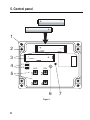
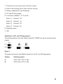
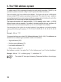
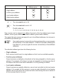
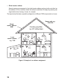
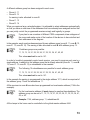
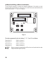
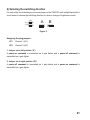
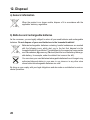
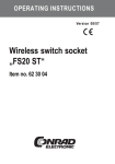
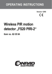
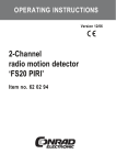
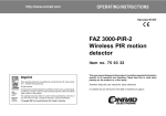
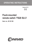
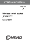
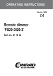
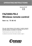
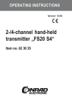
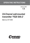
OPERATING INSTRUCTIONS Version 12/06 Wireless twilight transmitter „FS20 SD“ Item no. 62 30 19 Introduction Dear customer, Thank you for purchasing this product. This product meets the requirements of both current European and national guidelines. In order to preserve this condition and ensure the safe operation of the product we kindly ask you to carefully follow these operating instructions! Please read the operating instructions completely and observe the safety and operation notes before using the product! All company names and product names contained herein are trademarks of the respective owners. All rights reserved. Should you have any further questions, please contact our technical advisory service: Germany: Tel. no.: +49 9604 / 40 88 80 Fax. no.: +49 9604 / 40 88 48 e-mail: [email protected] Mon. to Thur. 8.00am to 4.30pm Fri. 8.00am to 2.00pm 2 Table of contents Page 1. 2. 3. 4. 5. 6. 7. 8. 9. 10. 11. 12. 13. 14. Prescribed use ............................................................................................................... 4 Scope of delivery ........................................................................................................... 5 Explanation of icons ...................................................................................................... 5 Safety instructions ......................................................................................................... 6 a) General information ................................................................................................ 6 b) Batteries and rechargeable batteries .................................................................... 6 Control panel ................................................................................................................. 8 The FS20 address system .......................................................................................... 10 Preparations for operation .......................................................................................... 15 a) Opening the casing .............................................................................................. 15 b) Inserting the batteries ........................................................................................... 15 c) Selecting the installation location, installation .................................................... 15 Programming/operation ............................................................................................... 17 a) Manual switching, address transmission ............................................................. 18 b) Programming the brightness response thresholds ............................................. 19 1. Setting both channels to different threshold values ..................................... 19 2. Setting both channels to the same threshold value ..................................... 19 3. Deleting a programmed switching threshold ................................................ 19 c) Programming the switching command type ........................................................ 20 d) Selecting the switching direction ......................................................................... 21 e) Programming the filter time .................................................................................. 22 f) Programming the FS20 timer function ................................................................. 23 g) Using several transmitters ................................................................................... 23 h) Setting the house code ........................................................................................ 24 i) Setting the addresses ........................................................................................... 24 Information on the range ............................................................................................. 26 Handling ....................................................................................................................... 27 Maintenance and cleaning .......................................................................................... 27 Disposal ....................................................................................................................... 28 a) General information .............................................................................................. 28 b) Batteries and rechargeable batteries .................................................................. 28 Technical specifications .............................................................................................. 29 Declaration of conformity (DOC) ................................................................................. 29 3 1. Prescribed use The ‘FS20 SD’ radio twilight transmitter is designed to remotely control various components from the FS20 wireless control system. It can remotely control these components on 2 channels, depending on the intensity of the ambient brightness. The brightness response thresholds as well as the type of switching command format on the receiver, the switching direction and the filter time for avoiding fast switching operations can each be programmed separately for each channel. In addition, the timers of the respective FS20 receivers can be programmed from the twilight transmitter. The device is housed in a dust and splash-proof casing (IP 65) and is therefore suitable for outdoor use. No cables are required to install the transmitter thanks to its battery operation. Depending on the quality of the batteries used, a battery life of several years is possible, due to the extremely low power consumption. Any use other than the one described above may damage the product and can also increase the risk of short-circuit, fire, electric shock, etc. No part of the product may be modified or adapted and the casing must not be opened. All the safety instructions and installation notes in this manual must be observed without fail. 4 2. Scope of delivery • ‘FS20 SD’ radio twilight transmitter • User manual 3. Explanation of icons The icon with a lightning flash in a triangle is used to alert you to potential personal injury hazards such as electric shock. The icon with an exclamation mark in a triangle points to important instructions in this user manual that must be observed. The ‘hand’ symbol provides special information and advice on operating the device. 5 4. Safety instructions The product’s guarantee becomes invalid, if the product is damaged as a result of the failure to observe these operating instructions! We do not assume any liability for any resulting damages! Nor do we assume liability for damage to property or personal injury caused by improper use or failure to observe the safety instructions. In such cases the product’s guarantee becomes invalid. Dear customer, the following safety instructions are intended to protect you as well as the device. Please take time to read through the following points: a) General information • If you are not sure how to assemble, connect and install the device or if you have doubts about its mode of operation, contact a skilled technician. • For safety and licensing (CE) reasons any unauthorised alterations to and/or modification of the product are not permitted. • When its casing is properly closed, this product is suitable for use outdoors (protection class IP65). • This product is not a toy and should be kept out of the reach of children. • Do not leave packaging material lying around. This may become a dangerous plaything in the hands of children. • Handle the product with care; knocks, blows or even a fall from a low height can damage it. b) Batteries and rechargeable batteries • Keep batteries/rechargeable batteries out of the reach of children. • Make sure that the polarity is correct when inserting batteries/rechargeable batteries. • Do not leave batteries/rechargeable batteries lying around as they could be swallowed by children or pets. In such case seek immediate medical care. • Leaking or damaged batteries/rechargeable batteries may cause acid burns, if they come into contact with skin. Therefore, please make sure you use suitable protective gloves. • Make sure that batteries/rechargeable batteries are not short-circuited or thrown into a fire. 6 They might explode! • Never disassemble batteries/rechargeable batteries! • Conventional batteries must not be recharged. They might explode! • If the device is not used for a longer period of time (when stored, for example), remove the inserted batteries/rechargeable batteries to prevent them from leaking and causing damage. The radio twilight transmitter can be operated using rechargeable batteries. However, due to the lower voltage of rechargeable batteries in comparison to other standard batteries (rechargeable battery = 1.2V, standard battery = 1.5V), the battery life and also the IR-range are reduced. As rechargeable batteries are more sensitive to temperature than standard batteries, the battery life of rechargeable batteries can be very short in winter. Rechargeable batteries may therefore need to be replaced more often. Due to the low power consumption, a battery life of 10 years is possible when high-quality alkaline batteries are used (depending, amongst other things, on the switching frequency). 7 5. Control panel + + - 1 2 - 5 + 3 4 - + K.1 K.2 JP1 AUS JP2 EIN 1 2 3 4 6 Figure 1 8 7 1 Screw hole for cover (one in each of the four corners) 2 Hole for wall mounting (one in each of the four corners) 3 Battery compartment for two AA batteries 4 JP1 and JP2 plug jumpers 5 Four buttons, labelled ‘1’, ‘2’, ‘3’ and ‘4’ Button ‘1’: Channel 1, Off Button ‘2’: Channel 1, On Button ‘3’: Channel 2, Off Button ‘4’: Channel 2, On 6 Brightness sensor 7 LED Significance of JP1 and JP2 plug jumpers: The switching pattern of the radio twilight transmitter ‘FS20SD’ can be set using these plug jumpers. K.1 K.2 JP1 A B JP2 Figure 2 The jumper can be set to two different positions for the JP1 and JP2 plug jumpers: Position Switching pattern A ON for ‘dark’, OFF for ‘light’ B ON for ‘light’, OFF for ‘dark’ 9 6. The FS20 address system To enable several FS20 components (including the radio twilight transmitter ‘FS20SD’) to be operated in parallel, extensive coding is used to protect the radio transmission. The code consists of a ‘house code’ and an ‘address’. The house code serves to differentiate between multiple FS20 systems operating simultaneously. This means that your neighbour can use the same wireless control system and the two systems will not interfere with each other (provided that the house code has been programmed differently). The house code consists of 8 base-four digits (1,2,3,4) meaning that in total 48 (= 65536) different house codes are possible. This makes it extremely unlikely that your neighbour will use the same house code (assuming that you do not use ‘simple’ house codes). The second part of the code is the so-called ‘address’. Every address is a four-digit number made up of the following 16 numbers: 11, 12, 13, 14, 21, 22, 23, 24, 31, 32, 33, 34, 41, 42, 43, 44 Example: Address 11 22 This means that there are a total of 256 different addresses (16x16 = 256). The addresses are divided into four address types (available number is in brackets): • Single addresses (225) • Function group addresses (15) • Local master addresses (15) • Global master address (1) Each address consists of two parts. Part 1 is the ‘address group’, part 2 is the ‘subaddress’. Example: Address 11 22 = address group ‘11’, subaddress ‘22’ 10 The number ‘44’ has a special meaning. Please see the table on the next page. Address group Single address Subaddress 44 44 Function group address 44 44 Local master address 44 44 Global master address 44 44 44 = This value must be set to ‘44’. 44 = This value must not be set to ‘44’. Possible values are: 11, 12, 13, 14, 21, 22, 23, 24, 31, 32, 33, 34, 41, 42, 43 Every receiver can be assigned one address from each of the four address types (single address, function group address, local master address, global master address). This means that each receiver can respond to up to four different addresses, but only ever to one address per address type. If you need a receiver to respond to more than one transmitter, you can program the transmitters to the same address or, if different transmitter address types have been set, you can program the receiver consecutively to these different addresses. The individual address types have the following function: • Single addresses Each receiver should be set to a single address so that it can be controlled separately. • Function group addresses Several receivers are defined as a functional unit by being assigned to a function group address. If, for example, all the lamps in a house are assigned to a function group, then all the lamps in the entire house can be switched on or off by pressing one button. • Local master addresses Several receivers are spatially defined as one unit and controlled via the local master address. If, for example, all the receivers in a room are each allocated to a local master address, then all you need to do is press one button when leaving the room to switch off all the consumer loads in the room. 11 • Global master address Several receivers are assigned to the global master address and are jointly controlled via this address. All the consumer loads can easily be switched off simply by pressing one single button when leaving a house, for example. The figure below illustrates a possible configuration of different FS20 components in a house: House code, e.g. 1234 1234 Global master address 4444 Function group 44xx, e.g. 4411 ceiling lamps A Local master address, e.g. 1144 D 112 2 114 4 444 4 113 1 114 4 444 4 B 121 1 111 1 114 4 441 1 444 4 121 2 441 1 444 4 141 2 444 4 141 1 441 1 444 4 C 131 1 441 1 444 4 Figure 3: Example of an address assignment 12 A different address group has been assigned to each room: • Room A: 11 • Room B: 12 An awning is also allocated to room B. • Room C: 13 • Room D: 14 When you require a large, extended system, it is advisable to select addresses systematically so that you have an overview of the addresses that have already been assigned and so that you can jointly control the programmed receivers simply and logically in groups. If you plan to use a number of different FS20 components, draw a diagram of the rooms and make a note of the location of the devices to be controlled and their addresses in the diagram. In the example, each room has been assigned its own address group (room A: 11, room B: 12, room C: 13, room D: 14). The awning is also allocated to room B with address group 12. 15 address groups are possible: 11, 12, 13, 14, 21, 22, 23, 24, 31, 32, 33, 34, 41, 42, 43 This value must not be set to ‘44’. In order to be able to separately control each receiver, you need to program each one to a single address. In addition to the address group that is already selected (room A: 11, room B: 12, room C: 13, room D: 14), a subaddress is also needed. The following 15 subaddresses are possible for each address group: 11, 12, 13, 14, 21, 22, 23, 24, 31, 32, 33, 34, 41, 42, 43 This value must not be set to ‘44’. In the example the awning is programmed to the single address 1211, which is comprised of the address group 12 and the subaddress 11. All the receivers in room A have also been programmed to a local master address (1144 in the example). For the local master address 44 must always be used as the subaddress. The address group can be set to 11, 12, 13, 14, 21, 22, 23, 24, 31, 32, 33, 34, 41, 42, or 43. Example: 1144, address group 11, subaddress 44 All the lamps in the house can be controlled via the global master address 4444. 13 The awning was deliberately not programmed to this address and can therefore only be addressed via its single address (1211). It must be operated separately in this example. The ceiling lamps in all the rooms are also combined in a function group (4411 in the example, address group 44, subaddress 11) and can therefore be jointly controlled. For a function group 44 must always be used as the address group. The subaddress can be set to 11, 12, 13, 14, 21, 22, 23, 24, 31, 32, 33, 34, 41, 42, or 43. Example: 4411, address group 44, subaddress 11 14 7. Preparations for operation a) Opening the casing Unscrew the four screws on the top side of the radio twilight transmitter using a suitable screwdriver and remove the casing cover. Do not straighten any of the components in the radio twilight transmitter just so that it ‘looks better’! Do not turn any setting controls or setting potentiometers! b) Inserting the batteries Insert two AA batteries, making sure that the polarity is correct. Useful diagrams are located in the two battery compartments. Also see figure 1. Leave the casing open. Do not tighten the screws on the casing cover yet. The radio twilight transmitter must first be installed/programmed. c) Selecting the installation location, installation When selecting an installation location choose a place where no moving shadows (for example, from trees, houses, street lights, etc.) can unsettle the sensor. The installation location should also be selected so that the radio twilight transmitter is protected from snow. A shady, roofed installation location on the exterior wall of a building, such as under a porch or under the roof, is ideal. The sensor should not be positioned on the side of a building that receives direct sunlight. The northern side of a building is preferable. When installed in a publicly accessible location, the sensor should be mounted so that it is out of reach and is protected from damage/vandalism. Proceed as follows to mount the device: • Position the lower part of the casing at the desired installation location and mark the installation location through the four mounting holes. • Depending on the installation location, suitable holes should be drilled and appropriate dowels should be inserted, before the lower part of the casing is screwed tight. 15 Make sure not to damage any power supply lines, gas or water pipes – this may cause life-threatening danger! • For fastening only use lens head screws or machine screws with washers, and not countersunk screws! Due to their conical design, countersunk screws can damage the casing, which will then invalidate the guarantee! • After programming the radio twilight transmitter (see the following pages), the casing cover should be attached and secured with four screws. Carefully ensure that the seal fits the casing cover properly and is not crushed. Only then is the device dust and splash-proof according to protection class IP65! 16 8. Programming/operation Please note: In the delivery state the components of the FS20 wireless control system do not respond to remote control commands. They must first be addressed by the transmitter according to the instructions provided in the respective switching device’s user manual. Only then is it possible to control the device with the transmitter. All settings such as the addresses, codes, brightness response thresholds, filter time, switching direction and timer programming can be programmed using the four buttons and the two plug jumpers on the circuit board inside the radio twilight transmitter. Once the radio twilight transmitter has been programmed it functions fully independently and does not require any operation whatsoever. The radio twilight transmitter is part of the FS20 wireless control system. For that reason it is of course possible to integrate it into the that code and addressing system, in case you wish to operate various devices of the FS20 wireless control system parallel. During the initial operation of the radio twilight transmitter, a random house code and the standard address assignment of the transmission channels are automatically configured. It is only necessary to change these automatically generated settings, if you wish to operate more than one device from the FS20 wireless control system. You can change or adjust the house code and addressing whenever you want. For information on coding and addressing, please read sections 6 and 8. 17 a) Manual switching, address transmission To test the radio connection or transmit the transmitter addresses to the receiver, you can manually switch the transmitter. For this purpose, four small buttons are located inside on the circuit board (marked 1, 2, 3 and 4 in the figure): - + - + + K.1 K.2 JP1 AUS JP2 EIN 1 2 3 4 Figure 4 The button assignment for the four buttons ‘1’, ‘2’, ‘3’ and ‘4’ is as follows: Press button ‘2’: Switch on channel 1 Press button ‘1’: Switch off channel 1 Press button ‘4’: Switch on channel 2 Press button ‘3’: Switch off channel 2 18 When a command is transmitted the LED on the circuit board inside the radio twilight transmitter lights up briefly. b) Programming the brightness response thresholds This programming step sets the brightness response thresholds at which the switching processes should be triggered. In the delivery state, no brightness response thresholds are programmed. Programming should be carried out at a time when the brightness is currently at the level at which the radio twilight transmitter should transmit a switching command. The brightness response thresholds can be programmed separately for each of the two channels. The same procedure is used for both channels. Therefore, we have included information for channel 2 in brackets. 1. Setting both channels to different threshold values • Press button ‘1’ (for channel 2: button ‘3’) until the LED on the radio twilight transmitter’s circuit board lights up briefly (approx. 5 seconds). • Place the cover on the radio twilight transmitter. After a minute, the current brightness level is measured and stored as the switching threshold for channel 1 (or channel 2). 2. Setting both channels to the same threshold value • Press button ‘1’ until the LED on the radio twilight transmitter’s circuit board lights up briefly (approx. 5 seconds). • Within the next minute, press button ‘3’ until the radio twilight transmitter’s LED briefly lights up again (approx. 5 seconds). • Place the cover on the radio twilight transmitter. After a minute, the current brightness level is measured and stored as the switching threshold for both channels. 3. Deleting a programmed switching threshold • Press button ‘1’ (for channel 2: button ‘3’) until the radio twilight transmitter’s LED lights up briefly (approx. 5 seconds). • Briefly press one of the four buttons within the next minute. Afterwards, the value for the switching threshold for channel 1 (or channel 2) is erased from the memory. 19 c) Programming the switching command type In the delivery state the ‘FS20 SD’ radio twilight transmitter transmits power-on as well as power-off commands on each programmed channel when the brightness level exceeds or falls below the set brightness threshold value. Each of the two channels can, however, also be programmed so that they only transmit power-on or power-off commands. Programming channel 1: • Only transmit power-on commands: Keep buttons ‘2’, ‘3’ and ‘4’ simultaneously pressed until the LED lights up briefly (approx. 5 seconds) • Only transmit power-off commands: Keep buttons ‘1’, ‘3’ and ‘4’ simultaneously pressed until the LED lights up briefly (approx. 5 seconds). Programming channel 2: • Only transmit power-on commands: Keep buttons ‘1’, ‘2’ and ‘4’ simultaneously pressed until the LED lights up briefly (approx. 5 seconds) • Only transmit power-off commands: Keep buttons ‘1’, ‘2’ and ‘3’ simultaneously pressed until the LED lights up briefly (approx. 5 seconds) Deleting the settings In order to get both channels to transmit power-on and power-off commands once again, keep all four buttons simultaneously pressed until the LED lights up briefly (approx. 5 seconds). 20 d) Selecting the switching direction For each of the two channels you can use a jumper on the ‘FS20 SD’ radio twilight transmitter’s circuit board to choose the switching direction for when a change of brightness occurs. K.1 K.2 JP1 A B JP2 Figure 5 Assigning the plug jumpers : JP1: Channel 1 (K.1) JP2: Channel 2 (K.2) 1. Jumper set to left position (‘A’) A power-on command is transmitted as it gets darker and a power-off command is transmitted as it gets lighter. 2. Jumper set to right position (‘B’) A power-off command is transmitted as it gets darker and a power-on command is transmitted as it gets lighter. 21 e) Programming the filter time In normal operation, the ‘FS20SD’ wireless twilight transmitter measures the brightness once every minute. This could, on specific occasions, such as when shadows are cast, clouds move overhead, or vehicles with bright headlights drive by, cause unintentional switching operations to be triggered. Therefore, a so-called ‘filter time’ can be set for each of the two channels. In the delivery state this filter time is set to 4 minutes. This means that four brightness measurements must yield the same value (light or dark), before a switching command will be issued. You can, of course, change this default filter time; different filter times of 2, 4, 8 and 16 minutes are possible. This means that 2, 4, 8 or 16 brightness measurements must each lie above or below the programmed threshold value, in order for a switching command to be activated. To program the filter time, proceed as follows: • For channel 1 press button ‘2’ until the LED blinks (approx. 5 seconds) (for channel 2, press button ‘4’). • To select the filter time, press one of the four buttons: Button ‘1’: 2 minutes Button ‘2’: 4 minutes Button ‘3’: 8 minutes Button ‘4’: 16 minutes • The LED goes out and the selected filter time is programmed. 22 f) Programming the FS20 timer function The timers of the FS20 receivers belonging to the FS20 wireless control system can, of course, be programmed from the ‘FS20SD’ radio twilight transmitter. To program the timers, proceed as follows: • Briefly press (for fewer than 5 seconds) both buttons of the respective channel simultaneously: Channel 1: Buttons ‘1’ and ‘2’ Channel 2: Buttons ‘3’ and ‘4’ • The time measurement for the timer starts. • Simultaneously press the button combination again to stop the time measurement for the timer. For further information on programming the timer and its special functions (activate, deactivate, slow-on, slow-off while dimming etc.) see the instructions provided in the receivers’ respective user manuals. g) Using several transmitters In the delivery state each transmitter in the FS20 wireless control system has its own, randomly set house code. If you want to jointly control one or several receivers via different transmitters, you first need to coordinate the house codes of all the transmitters. The same house code must be set for each transmitter. Make sure you coordinate the transmitters before programming or operating the receivers for the first time, as the associated house code is also sent to the receiver during this procedure. The transmitters’ channels are already set to the same addresses and only need to be changed, if required. 23 h) Setting the house code For a description of the ‘house code’, please see section 6. Once the ‘FS20SD’ radio twilight transmitter’s batteries have been inserted, a random house code is selected. If you want to jointly control one or several receivers via different transmitters, you first need to coordinate the transmitters’ house codes. The same house code must be set for each transmitter. If required, this house code can be changed as follows: • Keep buttons ‘1’ and ‘3’ on the ‘FS20SD’ radio twilight transmitter pressed until the LED blinks about every second (approx. 5 seconds). • Afterwards, enter the 8-digit house code of your FS20 wireless control system using the buttons ‘1’, ‘2’, ‘3’ and ‘4’. The house code can only comprise the numbers 1, 2, 3 and 4. Example: 23141342 • After the eighth digit has been entered, the programming mode is exited automatically and the LED goes out. The house code is saved. i) Setting the addresses For a description of the ‘addresses’, please see section 6. A channel’s address comprises a two-digit address group and a two-digit subaddress. In the delivery state the address group ‘11’ is set for both channels. If several transmitters are to be operated at the same time and control different receivers, then different addresses need to be set on the transmitters. To set a single address (address group/subaddress), proceed as follows: • Press the buttons of the button combination for the desired channel simultaneously until the LED blinks about every second (approx. 5 seconds). Channel 1: Buttons ‘1’ and ‘2’ Channel 2: Buttons ‘3’ and ‘4’ 24 • Now enter a 2-digit address group and a 2-digit sub-address using the buttons ‘1’, ‘2’, ‘3’ and ‘4’. Example: 14 31 (= address group ‘14’, subaddress ‘31’) • After the fourth digit has been entered, the programming mode is exited automatically and the LED goes out. The desired address (address group and subaddress) is programmed. Please note: The address group 44 and the subaddress 44 both have a particular meaning. See section 6. This address system opens up a variety of possibilities. The functions, switching operation authorisations and assignments to the system’s individual receivers can be clearly delimited or combined for hand-held remote controls, automatic transmitters such as the ‘FS20 SD’ radio twilight transmitter and automatic timers such as the ‘FS20 ZE’. Example scenario: An ‘FS20 SD’ radio twilight transmitter, ‘FS20 ZE’ radio timer and an ‘FS20 SA’ surfacemounted remote switch are programmed to the same address. The ‘FS20 SD’ switches on an outdoor light as it gets darker while the ‘FS20 ZE’ can switch this light off again at 11 pm, for instance. Using the ‘FS20 SA’, the light can be manually switched at any time. 25 9. Information on the range Ranges and interference • The FS20 wireless control system works in the 868MHz range, which is also used by other radio services. Therefore devices that operate on the same or neighbouring frequencies may restrict both its operation and its range. • The specified range of up to 100m is the free-field range, which means the range with visual contact between the transmitter and receiver. In practice, however, walls, ceilings, etc. between the transmitter and the receiver may affect and reduce the range. Other causes of reduced ranges: • All types of high-frequency interference • Any buildings or vegetation • Conductive metal parts that are located near the devices or within or near their transmission path, for example, radiators, metallised insulation glass windows, reinforced concrete ceilings, etc. • Influence on the radiation pattern of antennas due to the distance from the transmitter or receiver to conductive surfaces or objects (also to human bodies or the ground) • Broadband interference in urban areas that reduces the signal-to-noise ratio; the signal is no longer recognised due to this ‘noise’ • Interference radiation resulting from insufficiently shielded electronic devices, for example, operating computers or similar 26 10. Handling Take note of all the safety instructions in this user manual. Due to the way it is constructed (protection class IP65) the radio twilight transmitter can be used outdoors, provided that its casing is fully and correctly closed. The product must be assembled properly and professionally. Normally the radio twilight transmitter is installed once and then remains fixed at the installation location. Depending on the installation location, check occasionally that the product is in perfect condition. 11. Maintenance and cleaning The product requires no servicing except for battery replacement. The average power consumption (standby, brightness measurement and radio transmission) is approx. 20μA. Thanks to this low power consumption, the batteries can last up to ten years. In spite of this, you should replace the batteries approximately every 3 years, by way of precaution, as the batteries are more likely to leak as they get older (when purchasing batteries, pay attention to the specified service life). We recommend that you clean the upper surface of the transparent casing cover every now and then, as over the course of time and depending on the installation location, dust particles or dirt may have gathered. For cleaning, use a soft cloth moistened with lukewarm water. Do not use solvent-based cleaning agents, as these may damage the surface of the plastic casing and its inscription. 27 12. Disposal a) General information When the product is no longer usable, dispose of it in accordance with the applicable statutory regulations. b) Batteries and rechargeable batteries As the consumer, you are legally obliged to return all your used batteries and rechargeable batteries. Do not dispose of your used batteries via the household rubbish! Batteries/rechargeable batteries containing harmful substances are marked with the following icons, which alert you to the fact that disposal via the household rubbish is prohibited. The identifiers for the respective heavy metals are: Cd=cadmium, Hg=mercury, Pb=lead (identifier is on the battery/rechargeable battery, for example, under the rubbish bin icons on the left). You can return your used batteries/rechargeable batteries free of charge to any authorised disposal station in your area, in our stores or in any other store where batteries/rechargeable batteries are sold! By doing so you comply with your legal obligations and also make a contribution to environmental protection. 28 13. Technical specifications • Range ..................................................... up to 100m (in free-field) • Radio frequency: ................................... 868.35MHz • Power supply: ........................................ 2 x AA batteries (preferably alkaline batteries) • Battery life: ............................................. several years • Brightness range: .................................. 0.5 to 5000 Lux 14. Declaration of conformity (DOC) We, Conrad Electronic, Klaus-Conrad-Straße 1, D-92240 Hirschau (Germany), hereby declare that this product complies with the fundamental requirements and other relevant regulations of directive 1999/5/EG. You can find the declaration of conformity for this product at www.conrad.com. . 29 30 31 http://www.conrad.com CONRAD IM INTERNET http://www.conrad.com Imprint These operating instructions are published by Conrad Electronic SE, Klaus-Conrad-Str. 1, D-92240 Hirschau/Germany. No reproduction (including translation) is permitted in whole or part e.g. photocopy, microfilming or storage in electronic data processing equipment, without the express written consent of the publisher. 100% recycling paper. Bleached without chlorine. The operating instructions reflect the current technical specifications at time of print.We reserve the right to change the technical or physical specifications. © Copyright 2006 by Conrad Electronic SE. Printed in Germany.