1
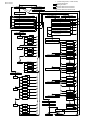
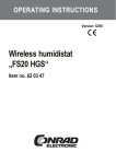
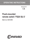
OPERATING INSTRUCTIONS Version 12/06 Load monitor „FS20 FMS“ Item no. 62 30 20 /* Item no. 62 30 20 Item no. 62 30 23 periodic blinking of LED (* = number of blinks) Continue automatically Briefly press button >5 >12 Operating mode Factory setting >12 >5 >2 Press the button for at least 2 seconds >5 Press the button for at least 5 seconds >12 Saving the setting >5 Press the button for at least 12 seconds >2 >2 Set-up mode >2 Preselection house code mode /1 Preselection adress code mode /2 >5 >5 >5 >5 >5 >2 "Negative" flank mode "Positive" flank mode no command /1 /3 Power-on command /2 Preselection "Positive" flank mode /4 Power-off command /3 Preselection "negative" flank mode /5 Preselection threshold value mode House code mode Digit 1 >2 >2 Value 1 /1 Value 2 /2 >2 Value 3 /3 >2 Value 4 /4 >2 Digit 2 >2 >2 >2 >2 >2 Value 1 /1 Value 2 /2 Value 3 /3 Value 4 /4 /4 >2 >2 Power-on command, timer function, /6 then power-off >5 >2 >5 Timer funct., then power-on command, /5 but only if the master is still active >2 >2 >5 Timer funct., then power-on command >2 >2 >5 >5 >5 >5 >2 Timer-Mode >5 >5 Hours entry >5 >2 >2 >5 >5 >2 >2 >5 >2 >5 1 hour /1 2 hours /2 3 hours /3 4 hours /4 0 hours /- >2 >5 >5 >5 >5 >5 Tens of minutes entry >5 >5 >2 >2 10 minutes /1 >5 20 minutes /2 >5 >2 Digit 8 >2 >2 >2 >2 Value 1 /1 Value 2 /2 Value 3 /3 Value 4 /4 >5 >2 >5 0 minutes /- >5 Minutes entry >5 >2 >2 >2 1 minutes /1 >5 2 minutes /2 >5 9 minutes /9 >5 Adress code mode Digit 1 >2 >2 >2 >2 Value 1 /1 Value 2 /2 Value 3 /3 Value 4 /4 >5 >2 >2 >5 0 minutes /- >5 >2 >5 Tens of seconds entry >5 >2 >2 >5 >5 >5 >2 >5 >2 50 minutes /5 10 seconds /1 20 seconds /2 >5 >5 >2 Digit 2 Value 1 /1 >5 >2 Value 2 /2 >5 >2 Value 3 /3 >2 >2 Value 4 /4 >2 >2 50 seconds /5 0 seconds /- >2 >5 >5 >5 >5 Seconds entry 1 second /1 >5 >2 >5 >2 2 seconds /2 >2 >5 >2 Threshold value mode >2 Digit 4 >2 >2 >2 >2 Value 1 /1 Value 2 /2 Value 3 /3 Value 4 /4 9 seconds /9 Automatic measurement >5 0 seconds />5 >5 >2 >5 >2 >5 Level 1 /1 >2 >5 >5 No level >2 Level 7 /7 >5 >2 Introduction Dear customer, Thank you for purchasing this product. This product meets the requirements of both current national and European guidelines. Please read the user manual completely and observe the safety and operation instructions before using the product! This user manual belongs to this product. It contains important information specific to its operation and handling. Please bear this in mind when passing on the product to a third party. Therefore keep this user manual for future reference! All company and product names contained herein are trademarks of their respective owners. All rights reserved. For more inquiries, contact or consult our technical service: Germany: 2 Tel. no.: +49 9604 / 40 88 80 Fax. no.: +49 9604 / 40 88 48 e-mail: [email protected] Mon. to Thur. 8.00am to 4.30pm Fri. 8.00am to 2.00pm Table of contents Page 1. 2. 3. 4. 5. 6. 7. 8. 9. 10. 11. 12. 13. 14. 15. 16. 17. 18. Prescribed use ................................................................................. 4 Scope of delivery ............................................................................. 4 Explanation of icons ......................................................................... 5 Safety instructions ........................................................................... 6 Description of functions ................................................................... 8 Control panel .................................................................................... 9 Initial operation ............................................................................... 10 Operation/basic function ................................................................ 11 a) Addressing the receiver .......................................................... 12 b) Manual switching ..................................................................... 12 c) Switching via the master device ............................................. 12 Programming .................................................................................. 13 a) Example ‘turning on the slave when the master is turned off’ .. 14 b) Setting the commands ............................................................. 16 1. Setting the ‘positive flank mode’ ........................................ 16 2. Setting the ‘negative flank mode’ ...................................... 16 3. Setting the ‘command mode’ ............................................. 17 4. Setting the timer duration (‘timer mode’) .......................... 20 c) Setting the threshold value ..................................................... 22 Restoring the factory settings ....................................................... 24 FS20 address system basics ........................................................ 25 Example of an address assignment ............................................. 27 Handling ......................................................................................... 29 Maintenance and cleaning ............................................................ 30 Disposal .......................................................................................... 31 Information on the range ............................................................... 31 Declaration of conformity (DOC) .................................................. 32 Technical specifications ................................................................ 33 3 1. Prescribed use The ‘FS20 FMS’ load monitor functions exclusively in conjunction with the FS20 wireless control system. The ‘FS20 FMS’ registers when a connected electric consumer load (master, 230V~/50Hz, load current max. 16A) is turned on or off and, with this information, controls any number of switching receivers in the FS20 system. Additional functions are described in detail in section 5. Any use other than the one described above may damage the product and cause other dangers. Read these operating instructions thoroughly and carefully, as they contain a great deal of important information for the operation and handling. 2. Scope of delivery • Load monitor ‘FS20 FMS’ • User manual • Flowchart for programming 4 3. Explanation of icons The icon with a lightning flash in a triangle is used to alert you to potential personal injury hazards such as electric shock. The icon with an exclamation mark in a triangle points to important instructions in this user manual that must be observed. The ‘hand’ symbol indicates special tips and information on operation. 5 4. Safety instructions The product’s guarantee becomes invalid if the product is damaged as a result of failure to observe these operating instructions. We do not assume any liability for any resulting damages! Nor do we assume liability for damage to property or personal injury caused by improper use or failure to observe the safety instructions. In such cases the product’s guarantee becomes invalid! • For safety and licensing (CE) reasons any unauthorised alterations to and/or modification of the product are not permitted. • Do not use this product in hospitals or medical institutions. Although the product emits only relatively weak radio signals, these may cause lifesupport systems to malfunction. This may also be the case in other areas. • The product is designed in accordance with protection class I. The only voltage source that may be used is that of the correct power socketoutlet (230V~/50Hz) with the protective earth conductor of the public power supply system. • The product is not a toy and should be kept out of the reach of children. Therefore take particular care when children are around! • Make sure the product does not become damp or wet; it is only suitable for use in dry indoor locations (not bathrooms or similar). Otherwise there is the risk of a life-threatening electric shock! • Protect the product against heat, cold, and direct sunlight while in storage or operation. • Never dismantle the product! There is danger of a fatal electric shock! 6 • Do not leave packaging material lying around. This may become a dangerous plaything in the hands of children. • The accident-prevention regulations, established by the Employer’s Liability Insurance Association for electrical equipment and facilities, must be adhered to in commercial facilities. • Consult a skilled technician if you have doubts about the mode of operation, safety or connection of the device. • Handle the product with care; knocks, blows or even a fall from a low height can damage it. 7 5. Description of functions The ‘FS20 FMS’ load monitor registers when a connected electric consumer load (master) is turned on or off and, with this information, remotely controls any number of switching receivers in the FS20 system, for example, an ‘FS20 ST’ wireless switch socket. The switching direction can be selected. With the factory settings the ‘FS20 FMS’ transmits a power-on command when the connected consumer is switched on and a power-off command when it is switched off. The opposite function can be programmed (power-on command when the consumer is turned off and power-off command when it is turned on). The triggering threshold can be adjusted in 7 steps, allowing consumer loads to be monitored that consume power while in standby mode. Due to the integration in the FS20 address and coding system, the data transfer within the FS20 wireless control system is very secure and several neighbouring systems can be operated simultaneously (for instance, if your neighbour uses the same system). The ‘FS20 FMS’ can be operated using any conventional earthed socket (230V~/50Hz). A consumer load with or without contact protection can be plugged into the socket of the ‘FS20 FMS’. The consumer load can have a maximum power consumption of up to (depending on the earthed socket!) 3680VA (230V~/16A). The ‘FS20 FMS’ is operated and programmed using the button on its front side, the status and program messages are displayed with an LED. 8 6. Control panel Button with integrated LED Socket for consumer loads (230V~/50Hz, max. 16A) On the back side there is an earthed plug that must be plugged into a socket of the public power supply system (230V~/50Hz). 9 7. Initial operation • Plug the ‘FS20 FMS’ into a power socket with an earthing conductor (public power supply 230V~/50Hz). • Plug the device to be monitored (hereafter ‘master’ or ‘master device’) into the socket on the front side of the ‘FS20 FMS’. • Do not turn the master device on yet! • Install the desired radio receiver of the FS20 switching system according to its installation and user manual. Plug, for example, an ‘FS20ST’ switch socket into an earthed socket and connect a consumer to it, for instance, a lamp. Hereafter the receiver will be referred to as ‘slave’ or ‘slave device’. 10 8. Operation/basic function Please note: In the delivery state the receiver components of the FS20 wireless control system do not respond to remote control commands. They must first be addressed according to the instructions provided in the respective device’s user manual. Afterwards, the factory settings of the ‘FS20 FMS’ are active. In this case turning the master on or off causes a power-on or power-off command, respectively, to be transmitted. The ‘FS20 FMS’ has a factory set, random house code and a random address code that are transmitted when a receiver is registered. You only have to changes these if you plan to expand your system with additional FS20 components, or if you wish to integrate the ‘FS20 FMS’ in an existing FS20 wireless control system. The master device must consume at least 20mA in order for it to be recognised as a load by the ‘FS20 FMS’. This means that the minimum power consumption of the master device is around 4.6W. For devices that consume less power, proper functioning cannot be ensured. 11 a) Addressing the receiver If you wish to use the basic settings of the ‘FS20 FMS’, proceed as follows (otherwise see the sections near the end of this manual!): • Place the corresponding receiver in the mode in which it can receive addressing data (for a wireless switch socket ‘FS20 ST’ you must press and hold its control button for more than 15 seconds, until the LED begins to blink). • Briefly press the control button of the ‘FS20 FMS’. • The receiver (for instance, the ‘FS20 ST’) confirms the reception (status indicator stops blinking or goes out). b) Manual switching • Briefly pressing the button on the ‘FS20 FMS’ transmits a TOGGLE command (switching back to the previous switch status). • The slave device is turned on or off. c) Switching via the master device • Turn the master device on (power consumption of at least approx. 4.6W!). The ‘FS20 FMS’ recognises this and sends a switching command. The slave device turns on. • Turn the master device off. The slave device also turns off. 12 You can now use the basic functions of the system. Please also read the following sections, if you require an extended system with several components or you wish to use the additional functions. 9. Programming To understand the following description of the programming steps, you will need the accompanying flowchart. The basic operating steps and displays are the same for all programming steps. You are guided through the operating steps by three displays of the control indicator (LED) of the ‘FS20 FMS’ that are always repeated. The LED shows, for how long the button has already been pressed: • Briefly pressing the button is indicated by the LED lighting up once • If the button is held down for longer, the LED lights up for approx 2 seconds and then goes out. • After 5 seconds the LED lights up again. • After a total of 12 seconds the LED goes out again. • In the setting modes the LED blinks periodically. The number of blinks can always be found on the right behind the slash (/) in the flowchart. In the following section an example of how to set up the device is described in detail. The settings that follow are described in short-hand with respect to the flowchart and are, for the most part, meant to be commentary for the flowchart. Please note the legend in the upper right-hand corner of the diagram. The starting point is always the ‘operating mode’ in the upper left-hand corner. From every set-up mode you can return to the operating mode by pressing the button for more than 5 seconds without making any changes (escape function). If no button is pressed for 60 seconds, then you will also be returned to the operating mode without any changes being made. 13 a) Example ‘turning on the slave when the master is turned off’ With the factory settings the function ‘power-on command’ is active when the master is turned on and the ‘power-off command’ when it is turned off. If you desire the opposite functionality, for instance if the device is meant to signal when the washing machine or dryer is done (power consumption sinks), then you must make the following settings: • Press the button on the ‘FS20 FMS’ for longer than 5 seconds. The LED lights up for 2 seconds and then goes out. After 5 seconds the LED lights up again. Release the button. • The LED blinks in intervals, 1x each. • The ‘FS20 FMS’ is now in the set-up mode for ‘preselection house code mode’. • Now press the control button briefly 3 times in a row. The LED blinks in intervals, 4x each. The ‘FS20 FMS’ is now in the set-up mode ‘preselection positive flank mode’. • Press the button until the LED goes out (approx. 2 seconds). The ‘FS20 FMS’ is now in ‘positive flank mode’. • The LED blinks in intervals, 1x each. The ‘FS20 FMS’ is now in command mode ‘no command’. • Now press the button 2 x. The LED blinks in intervals, 3x each. • Press the button for 2 seconds. The ‘FS20 FMS’ is in command mode ‘power-off command’. After a total of 2 seconds, the LED goes out. Release the button. 14 • The new switching command is saved and the ‘FS20 FMS’ returns to its normal operating mode. • You must now repeat the procedure for the ‘negative flank mode’ and in the command mode set the command ‘power-on command’. 15 b) Setting the commands Please note: If you accidentally press the button one time too many in a given menu, you can return to the beginning of the menu (LED blinks in intervals, 1x each) by repeatedly pressing the button briefly. 1. Setting the ‘positive flank mode’ ‘Positive flank mode’ means that the switching command for the slave device is transmitted when the master device is turned on (when the power consumption of the consumer load rises). The factory setting here is ‘power-on command’. This can be changed as follows: • From the normal operating mode press the control button on the ‘FS20 FMS’ for 5 seconds (LED goes out after 2 seconds and lights up again after 5 seconds). • Release the button, the LED blinks in intervals, 1x each • Press the button briefly 3x, the LED blinks in intervals, 4x each • Press and hold the button for 2 seconds, LED goes out, release the button, LED blinks in intervals, 1x each • Now select one of the commands in the command mode (see ‘3. Setting the command mode’ on the next page); press the button the corresponding number of times (always pressing the button briefly). 2. Setting the ‘negative flank mode’ ‘Negative flank mode’ means that the switching command for the slave device is transmitted when the master device is turned off (see example 9. a). 16 • From the normal operating mode press and hold the control button for 5 seconds (LED lights up for 2 seconds and goes out, after 5 seconds the LED lights up again) • Release the button, the LED blinks in intervals, 1x each • Press the button briefly 4x, the LED blinks in intervals, 5x each • Press and hold the button for 2 seconds, (LED goes out after 2 seconds), then release the button, LED blinks in intervals, 1x each • Select the desired command (see ‘3. Setting the command mode’) with the control button. 3. Setting the ‘command mode’ After the switching flank has been selected, which switching command is sent to the slave device is set here. • First set the desired flank mode according to point 1 or 2, if not already done! • Then select the corresponding command mode according to the following description: X No Command This function means that when the ‘FS20 FMS’ is triggered, no switching command will be transmitted: fLED blinks in intervals, 1x each fPress and hold the control button for 2 seconds, LED goes out, release the button fSetting has been saved, the ‘FS20 FMS’ is in normal operating mode 17 Y Power-on command This function means that when the ‘FS20 FMS’ is triggered, a poweron command will be transmitted: fLED blinks in intervals, 1x each, briefly press the control button 1x, LED blinks in intervals, 2x each fPress and hold the control button for 2 seconds, LED goes out, release the button fSetting has been saved, the ‘FS20 FMS’ is in normal operating mode Z Power-off command This function means that when the ‘FS20 FMS’ is triggered, a poweroff command will be transmitted: fLED blinks in intervals, 1x each, briefly press the control button 2x, LED blinks in intervals, 3x each fPress and hold the control button for 2 seconds, LED goes out, release the button fSetting has been saved, the ‘FS20 FMS’ is in normal operating mode [ Timer function, then power-on command This command means that when the ‘FS20 FMS’ is triggered, the power-on command is only sent to the slave device after the programmed timer duration expires: fLED blinks in intervals, 1x each, briefly press the control button 3x, LED blinks in intervals, 4x each fPress and hold the control button for 2 seconds, the LED goes out, then release the control button; the ‘FS20 FMS’ is now in ‘timer mode’. 18 Set the desired timer duration (point ‘4. Setting the timer duration’ on the next page, also see the flowchart). \ Timer function, then power-on command; but only, if the master is still active This command means that when the ‘FS20 FMS’ is triggered, first the programmed timer duration expires. Only if the master device is still active is a power-on command sent to the slave device. If this operating mode is selected for the ‘negative flank mode’, then it is meant that the master device is not yet active again. fLED blinks in intervals, 1x each, briefly press the control button 4x, LED blinks in intervals, 5x each fPress and hold the control button for 2 seconds, the LED goes out, then release the control button; the ‘FS20 FMS’ is now in ‘timer mode’. ] Set the desired timer duration (point ‘4. Setting the timer duration’ on the next page, also see the flowchart). Power-on command, then timer function, then power-off command This command means that when the ‘FS20 FMS’ is triggered, the slave device is turned on immediately. After the programmed timer duration has elapsed, a power-off command is sent to the slave device. fLED blinks in intervals, 1x each, briefly press the control button 5x, LED blinks in intervals, 6x each fPress and hold the control button for 2 seconds, the LED goes out, then release the control button; the ‘FS20 FMS’ is now in ‘timer mode’. Set the desired timer duration according to point 4 (see also the flowchart). 19 4. Setting the timer duration (‘timer mode’) The timer enables a time delay for the switching of between one second (1s) and 5 hours (4h 59min 59s). • The LED blinks in intervals, 1x each, the hours can be entered for the timer. • Press the control button as many times as necessary until the desired number of hours has been entered, for instance, press 3x for 4 hours (LED blinks in intervals, 4x each). • Press and hold the control button for 2 seconds, LED goes out, release the button. The digit for the tens of minutes can now be entered on the ‘FS20 FMS’. • Press the control button as many times as necessary until the desired number of tens of minutes has been entered, for instance, press 4x for 50 minutes (LED blinks in intervals, 5x each). • Press and hold the control button for 2 seconds, the LED goes out, then release the control button. The digit for the single minutes can now be entered on the ‘FS20 FMS’. • Press the control button as many times as necessary until the desired number of minutes has been entered, for instance, press 8x for 9 minutes (LED blinks in intervals, 9x each). • Press and hold the control button for 2 seconds, the LED goes out, then release the control button. The digit for the tens of seconds can now be entered on the ‘FS20 FMS’. • Press the control button as many times as necessary until the desired number of tens of seconds has been entered, for instance, press 4x for 50 seconds (LED blinks in intervals, 5x each). If ‘0 seconds’ is chosen, the LED does not blink. If ‘0 hours’ is chosen, the LED does not blink. If ‘0 minutes’ is chosen, the LED does not blink. If ‘0 minutes’ is chosen, the LED does not blink. 20 • Press and hold the control button for 2 seconds, the LED goes out, then release the control button; the ‘FS20 FMS’ is now in seconds entry mode. • Press the control button as many times as necessary until the desired number of seconds has been entered, for instance, press 8x for 9 seconds (LED blinks in intervals, 9x each). If ‘0 seconds is chosen, the LED does not blink. From any single second entry mode you can end and save the settings. To do this press and hold the control button for 2 seconds, the LED goes out. Release the control button. The timer setting has been saved, the ‘FS20 FMS’ is in normal operating mode. 21 c) Setting the threshold value The threshold value setting enables the tripping behaviour of the ‘FS20 FMS’ to be adjusted to the power consumption of the master device in standby mode. Many devices consume power even when turned off, for instance if they have a standby function. For instance a garage door drive consumes a base amount of power as the power supply and radio receiver are always on standby. So that the ‘FS20 FMS’ does not react to this base power consumption, a threshold value can be set. The minimum threshold value for triggering is 20mA, the maximum value that can be suppressed is approx. 400mA. The set-up is half-automatic, but it can be corrected manually, for instance, if the base power consumption changes (variable base power consumption). For devices with no base power consumption (for instance, devices with a ‘real’ power switch), the threshold value does not need to be set. Proceed as follows: • Connect the master device to the ‘FS20 FMS’ and switch it to standby mode • From the normal operating mode press the control button on the ‘FS20 FMS’ for 5 seconds (LED goes out after 2 seconds and lights up again after 5 seconds). • Release the control button, the LED blinks in intervals, 1x each • Press the control button 2x briefly, LED blinks in intervals, 3x each, the ‘FS20 FMS’ is in the menu point ‘preselection threshold mode’. • Press and hold the control button for 2 seconds, LED goes out, release the button. 22 • The LED lights up again and the device records the base power consumption of the master device automatically and sets the corresponding threshold level (this procedure can take up to 20 seconds). If no device is connected or if there is no base power consumption, the most sensitive level 1 will be automatically selected (LED blinks in intervals, 1x each). If the base power consumption is too high, this will be indicated by the LED blinking quickly for approx. 3 seconds. The ‘FS20 FMS’ will then set the ‘least sensitive’ level 7 (LED blinks in intervals, 7x each). • If you wish to set a base power consumption that is different from the one set by the automatic measurement, you can do this afterwards by briefly pressing the control button on the ‘FS20 FMS’. The number of times the LED blinks signals which level has been set. If you are at level 7 and the control button is pressed again, it returns to level 1. • After a successful measurement/set-up, press the control button for 2 seconds. After the LED goes out, release the button. • The setting has been saved, the ‘FS20 FMS’ is in normal operating mode. Please note: If the power consumption of the master device happens to be just at the edge of the threshold value of the ‘FS20 FMS’, then it is theoretically possible that the slave device is constantly turned on and off. In order to stop this from happening, the ‘FS20 FMS’ switches into a 30 second pause cycle (signalled by the LED blinking quickly) when it recognises this phenomenon. 23 If a continuous change in the load is still recognised during this time, then the pause cycle is extended another 30 seconds. The ‘FS20 FMS’ does not return to its normal operating mode until the constantly changing load is no longer recognised. If you notice a problem like this, it makes sense to manually increase the threshold one level. All timer functions that are active are deactivated during the pause cycle. 10. Restoring the factory settings Proceed as follows to restore the factory settings: • Press the button for approx. 12 seconds (LED goes out after 2 seconds, on after 5 seconds and off again after 12 seconds) • Release the button • The factory settings have now been restored to the ‘FS20 FMS’. 24 11. FS20 address system basics The FS20 wireless control system (including the ‘FS20 FMS’) works with a ‘house code’. This means that your neighbour can also use the same wireless control system and the two systems will not interfere with each other (provided that the house code has been programmed differently). 256 different addresses can be set within a house code. These addresses are divided into 4 address types (available number is in brackets): • Single addresses (225) • Function group addresses (15) • Local master addresses (15) • Global master address (1) One address from each address type can be assigned to each receiver. This means that each receiver can respond to up to four different addresses, but only ever to one address per address type. If you need a receiver to respond to more than one transmitter, you can program the transmitters to the same address or, if different transmitter address types have been set, you can program the receiver consecutively to these different addresses. The individual address types have the following function: • Single addresses Each receiver should be set to a single address so that it can be controlled separately. 25 • Function group addresses Several receivers are defined as a functional unit by being assigned to a function group address. If, for example, all the lamps in a house are assigned to a function group, then all the lamps in the entire house can be switched on or off by pressing one button. • Local master addresses Several receivers are spatially defined as one unit and controlled via the local master address. If, for example, all the receivers in a room are each allocated to a local master address, then all you need to do is press one button when leaving the room to switch off all the consumer loads in the room. • Global master address Several receivers are assigned to the global master address and are jointly controlled via this address. All the consumer loads can easily be switched off simply by pressing one single button when leaving a house, for example. This address system opens up a variety of possibilities. For example, you can even implement access authorisations by assigning three garage doors to different single addresses and a joint function group (‘garage doors’). Several people can then each be given a hand-held transmitter with a relevant single address for one garage door, while all the garage doors can be opened via a hand-held transmitter with a programmed function group address or all the doors can be automatically closed in the evening via an FS20 timer. 26 The various address types and addresses are only set on the transmitter and these settings are transmitted to the receivers via the address assignment. 12. Example of an address assignment When you require a large, extended system, it is advisable to select addresses systematically so that you have an overview of the addresses that have already been assigned and so that you can jointly control the programmed receivers simply and logically in groups. House code, e.g. 1234 1234 Global master address 4444 Function group 44xx, e.g. 4411 ceiling lamps A Local master address, e.g. 1144 D 112 2 114 4 444 4 113 1 114 4 444 4 B 121 1 111 1 114 4 441 1 444 4 121 2 441 1 444 4 141 2 444 4 141 1 441 1 444 4 C 131 1 441 1 444 4 A different address group has been assigned to each room: • • • • Room A: 11 Room B: 12 (The awning is also assigned to room B) Room C: 13 Room D: 14 27 15 address groups are possible: 11, 12, 13, 14, 21, 22, 23, 24, 31, 32, 33, 34, 41, 42, 43 In order to be able to separately control each receiver, you need to program each receiver to a single address. A subaddress is also required in addition to the address group that is already selected (room A: 11, room B: 12, room C: 13, room D: 14). The following 15 subaddresses are possible for each address group: 11, 12, 13, 14, 21, 22, 23, 24, 31, 32, 33, 34, 41, 42, 43 In the example the awning is programmed to the single address 1211, which is comprised of the address group 12 and its subaddress 11. All the receivers in room A have also been programmed to a local master address (1144 in the example). For the local master address 44 is always set as the subaddress, while one of the 15 local master addresses (11, 12, 13, 14, 21, 22, 23, 24, 31, 32, 33, 34, 41, 42, 43) can be selected via the address group. Example: 1144, address group 11, subaddress 44 All the lamps in the house can be controlled via the global master address 4444. The awning was deliberately not programmed to this address and can therefore only be addressed via its single address (1211). It must be operated separately in this example. The ceiling lamps in all the rooms are also combined in a function group (4411 in the example, address group 44, subaddress 11) and can therefore be jointly controlled. To select one of the 15 function groups, you need to set 44 as the address group and a value between 11 and 43 (11, 12, 13, 14, 21, 22, 23, 24, 31, 32, 33, 34, 41, 42, 43) as the subaddress. 28 13. Handling The product should only be used in dry indoor areas. The following unfavourable conditions at the installation site, during operation or transport are to be avoided: • Moisture or excessive air humidity • Extreme cold or heat • Direct sunlight • Dust or flammable gases, vapours or solvents • Strong vibrations • Strong magnetic fields such as those found near machines or loudspeakers Never use the product immediately after it has been brought from a cold room into a warm one. The condensation water generated could destroy the product. Wait until the product has reached room temperature. This can take several hours. Do not handle the product with damp or wet hands! This is true for all electrical devices! The device must not be opened or taken apart. There are no serviceable parts inside the product. The licence (CE) and the guarantee/warrantee becomes invalid if you open/take apart the device. Make sure that the insulation of the entire product is neither damaged nor destroyed. Always check the product for damage before using it! 29 If you detect any damage, do NOT connect the product to the supply voltage! Life-threatening danger! This product is not a toy and should be kept out of the reach of children. Even a fall from a low height can damage the product. 14. Maintenance and cleaning This product does not require maintenance. Repairs or maintenance work may only be carried out by a skilled technician! Before cleaning, unplug the ‘FS20 FMS’ from the power supply and remove any cables or devices that are plugged into the ‘FS20 FMS’. Then clean the ‘FS20 FMS’ using a soft, clean, dry and lint-free cloth. To remove heavier dirt, use a cloth which is slightly moistened with lukewarm water. Do not use solvent-based cleaning agents, as these may damage the surface of the plastic casing and its inscription. Afterwards allow the ‘FS20 FMS’ to dry completely before you plug it back into the socket. 30 15. Disposal When the product is no longer usable, dispose of it in accordance with the applicable statutory regulations. 16. Information on the range • The FS20 wireless control system (including the ‘FS20 FMS’) works in the 868MHz range. This range is also used by other devices and radio services. Therefore devices that operate on the same or neighbouring frequency may restrict both the operation of the ‘FS20 FMS’ and its range. • The specified range of up to 100m is the so-called free-field range. This describes the range when there is direct visual contact between the transmitter and the receiver. In practice, however, walls, ceilings, etc. between the transmitter and the receiver may affect and reduce the range. Other causes of reduced ranges: • All types of high-frequency interference • Any buildings or vegetation • Conductive metal parts that are located near the devices or within or near their transmission path, for example, radiators, metallised insulation glass windows, reinforced concrete ceilings, etc. • Influence on the radiation pattern of antennas due to the distance from the transmitter or receiver to conductive surfaces or objects (also to human bodies or the ground) 31 • Broadband interference in urban areas that reduces the signal-to-noise ratio; the signal is no longer recognised due to this ‘noise’ • Interference radiation resulting from insufficiently shielded electronic devices, for example, operating computers or similar Please note: Do not place several wireless receivers (for example switch sockets) directly next to each other, because they can negatively affect each other (range may be reduced!).). Keep them separated by a distance of at least 20cm. 17. Declaration of conformity (DOC) We, Conrad Electronic, Klaus-Conrad-Straße 1, D-92240 Hirschau (Germany), hereby declare that this product complies with the fundamental requirements and other relevant regulations of directive 1999/5/EG. 32 You can find the declaration of conformity for this product at www.conrad.com. 18. Technical specifications and features Power supply: ......................................... 230V~/50Hz Power consumption: ............................... approx. 32mA Minimum threshold value for triggering: approx. 20mA (approx. 4.6W) Maximum load current: .......................... 16A Transmission frequency: ....................... 868.35MHz Modulation: ............................................. AM Range: ..................................................... up to 100m (free-field) Dimensions (W x H x D): ....................... 56mm x 134mm x 77mm 33 34 35 http://www.conrad.com CONRAD IM INTERNET http://www.conrad.com Imprint These operating instructions are published by Conrad Electronic SE, Klaus-Conrad-Str. 1, D-92240 Hirschau/Germany. No reproduction (including translation) is permitted in whole or part e.g. photocopy, microfilming or storage in electronic data processing equipment, without the express written consent of the publisher. 100% recycling paper. The operating instructions reflect the current technical specifications at time of print. Bleached without chlorine. © Copyright 2006 by Conrad Electronic SE. Printed in Germany. We reserve the right to change the technical or physical specifications.