1
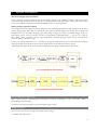
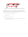
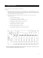
Infocharger(ICC & ICH) DC POWER SUPPLY/BATTERY CHARGER Important Notices! Thank you for choosing this charger system. This product can be used for both battery charger and DC power supply applications. For the staff and equipment safety it is necessary for the users to fully read and save this manual before working on this equipment. Description of the Symbols IMPORTANT NOTICE! Please follow the instructions. LIFE RISK! Please follow the instructions DANGER! Please follow the instructions otherwise the unit can be damaged or user can be hurt I Contents 1 Safety ...................................................................................................................................................... 3 2 System Description ................................................................................................................................ 4 3 Installation ............................................................................................................................................. 6 3rd1 Handling ............................................................................................................................................................................. 6 3rd2 Storage ................................................................................................................................................................................. 6 3rd3 Positioning .......................................................................................................................................................................... 6 3rd4 Connections ....................................................................................................................................................................... 7 3rd4.1 Ground (Earth) Connection ................................................................................................................................... 9 3rd4.2 Input connection....................................................................................................................................................... 9 3rd4.3 Battery connection .................................................................................................................................................... 9 3rd4.4 Output connection ................................................................................................................................................... 9 4 Switch ON and Switch OFF procedures ............................................................................................... 10 4th1 System Switch ON .......................................................................................................................................................... 10 4th2 System Switch OFF ........................................................................................................................................................ 10 5 Operating Instructions .......................................................................................................................... 11 5th1 Unit Operation ................................................................................................................................................................ 11 5th1.1 Operation modes .................................................................................................................................................... 11 5th2 Displays ............................................................................................................................................................................. 12 5th2.1.1 LCD Display................................................................................................................................................................ 12 5th2.1.2 MENU STRUCTURE .............................................................................................................................................. 13 5th2.1.3 Buttons ......................................................................................................................................................................... 15 There are mainly four buttons in the front panel. The functionalities of the buttons are given below. ..................... 15 6 Operating Procedures for Parallel Systems (Optional) ......................................................................... 17 7 Optional Modules ................................................................................................................................. 19 8 Maintenance ......................................................................................................................................... 20 9 Trouble Shouting .................................................................................................................................. 21 10 Technical Specifications ...................................................................................................................... 22 11 Block Diagrams .................................................................................................................................... 25 II 1 Safety For the staff and equipment safety, it is necessary for the users to fully read and understand this manual for DC Power Supply/Battery Charger before installation and operation. Avoid the sudden temperature changes, which can cause condensation inside the battery charger. Otherwise, wait at least for two hours before switching on. This product should be installed according to the instructions defined at ‘Positioning’. chapter 3.3 Do not close ventilation holes or other openings. Keep away the liquid and solid object entry inside the unit. Installation and commissioning have to be done by authorized technical service. Earth ( Ground ) connection should be done. Do not plug in/off the communication interface cables during bad weather conditions with lightning. To avoid the risk of fire, all the connections have to be done according to the suggested cable cross-sections. The cables should be isolated type and properly installed. Do not connect exceeding load than charger’s nominal power to the output. Maintenance and service of the equipment should be done by authorized technical service staff. In case of emergency (damage of the cabinet, front panel or connections etc.) switch off the battery charger, disconnect the input supply and inform the authorized technical service staff. The unit should be packed properly if it is needed to be moved. 3 2 System Description DC Power Supply Operation Mode If the equipment is being ordered as DC Power Supply, then the unit supplies a limited voltage and current value that is adjusted from the front panel to the connected DC load. The output voltage and current limits can be easily adjusted separately from the SETTINGS menu on the LCD panel. Battery Charger Operation Mode The equipment that is ordered as battery charger has the following specifications. This operation mode has 4 grades charging level depending on the battery type. These are initial charge, float charge, boost charge and temperature or auto controlled charging types. The charge voltages per cell are ; for initial charge: 2.04V, for float charge: 2.23V, for boost charge: 2.375V, for temperature controlled charge ; 2.17V at 00C / 2.29V at 500C. These values are factory set, but only temperature controlled charging values can be set from front panel according to the battery type. LVD ( Low Voltage Disconnector ) is available as an option. This function protects the batteries from deep discharge by disconnecting them from output during battery mode when the mains is absent. Additionally, the optional dry contact alarm card provides automation functionality to the device. ICC SYSTEM BLOCK DIAGRAM ICH SYSTEM BLOCK DIAGRAM Input EMI filters (Optional) These filters prevent electromagnetic interference between Infocharger, mains and loads. (EMI – electromagnetic interference) Your battery charger and loads are protected against high voltage. Bridge Rectifier This unit converts the AC voltage from mains to DC voltage.* *Available with ICH system. 4 DC / AC Inverter The inverter helps to obtain a very constant AC voltage level at the output by using DC voltage at the boost’s rectifier output. Rectifier This unit draws on the mains the power required to supply the inverter and to recharge the batteries. The alternating input voltage is rectified and distributed to the batteries. Low Voltage Protection (Optional) This type of protection is used as optional to prevent the deep discharge of the loads in the absence of the power at mains, and this voltage level can be adjustable at the front panel. Your Battery Charger’ features and benefits: Feature SMPS technology Transformerless design Microprocessor controller Benefit Compact design, small dimensions and low weight To use all the sources in optimum level. To observe carefully the failure conditions High input power factor To consume low reactive power PFC technology (only for ICC) Not to load the installation extra (cables, transformers, generators etc.) Clean power for the mains. Wide input voltage tolerance On-line double conversion topology Temperature Management This helps to reduce battery usage and guarantees battery to be fully charged and extends the battery life time. On-line operation even the mains is between 90 – 265 V for ICC and 176 – 265 V for ICH. The output voltage of the Infocharger is DC. Infocharger input total harmonic distortion is very low. This is very important for both the systems and batteries which are supplied by Infocharger. To calculate overloading time in a reliable way. To protect against over temperature. Modular System Architecture Parallel connection is available up to 7 units if you use InfoCharger ICH model as battery charger. Dry Contact Information Provides monitoring of your InfoCharger from your automation by relays and microprocessor. Effective output voltage regulation: (output voltage is not affected by changes on the mains input and load level.) High efficiency ( low power consumption) 5 3 Installation Check if the Infocharger has been subjected to any damage before unpacking it. If you notice any damage, please contact to transport firm. Check if all the additional parts have been supplied with the battery charger. Please make sure that the packing contains the following Infocharger User Manual Test Report Before the installation, please check if your Infocharger is customized following your special requirements (if any). The standard unit’s output voltage can be adjustable between 0, 30, 60, 150, 300VDC. 3rd1 Handling If needed to move the battery charger, it is obligatory to pack the unit. It is suggested to keep the original packing. 3rd2 Storage Please store the battery charger in an environment where the temperature is between –15 C and +70 C no receipt of direct sunlight, far from the heating, in a dry place. Environmental humidity must be between %20 and %95 (non-condensing). 3rd3 Positioning Infocharger and battery cabinet(if any) have to be positioned in an environment; No direct sun access, Must be dry, Far from the heating equipments No excessive dust Well-ventilated In order to maintain adequate ventilation of Infocharger and battery cabinets (if any), ensure the air vents are not blocked and leave at least 20 cm space at the rear side of the unit for ventilation. 6 3rd4 Connections Connections must be done by authorized technical service staff. Life risk for user! Temperature changes such as from cold to hot environment can cause condensation. It is dangerous to operate the Infocharger. Please wait at least two hours before making the connections. Connection terminals are on the front side of ICC models and on rear side of ICH models. Please take out the cover of the rear side to make the connections. Standard Infocharger connections are shown below. ICC Models; Load L+ (Gray) Battery L+ (Gray) * Ground (Yellow-Green) Input Phase (Gray) Load L- (Blue) Input Neutral (Blue) Battery L- (Blue) * 1 PHASE INPUT * Battery connection terminal is available with LVD option. 7 ICH Models; Load L+ (Gray) Ground (Yellow-Green) Battery L+ (Gray) * Input Phase (Gray) Load L- (Blue) Input Neutral (Blue) Battery L- (Blue) * 1 PHASE INPUT Ground (Yellow-Green) Load L+ (Gray) Input R Phase (Gray) Battery L+ (Gray) * Input S Phase (Gray) Load L- (Blue) Input T Phase (Gray) Battery L- (Blue) * Input Neutral (Blue) 3 PHASE INPUT * Battery connection terminal is available with LVD option. Please follow the instructions as explained below. 8 3rd4.1 Ground (Earth) Connection Inforcharger ground (earth) connections have to be done. The input ground terminals of the Infocharger should be connected to a reliable (low resisted) ground The grounding connection of the loads can be done over the output grounding contactor. The grounding connection of the external battery cabinet(if any) should be done over the same battery grounding contactor. The connection between the grounding unit of the Infocharger and the ground can be made according to the minimum cross-sectioned cables which are given in the technical specifications table below. 3rd4.2 Input connection The connections between the distribution frame and Infocharger for phase, neutral and ground are explained as below; FOR ICC: The Phase, Neutral and ground must be connected to their contactors on the front panel with a 2.5 mm2 cross-section multi-vein cable. FOR ICH: For single phase models, the Phase, Neutral and ground must be connected to their contactors on the back panel with a 10 mm2 cross-section multi-vein cable. For three phase models, the R, S, T, Neutral and ground must be connected to their contactors on the back panel with a 4 mm2 cross-section multi-vein cable. Changes on distribution panel have to be done by authorized persons only. 3rd4.3 Battery connection The batteries must be connected to the L+ (positive) and L- (negative) points properly (If LVD is used with device, the batteries must be connected to B+ and B- terminals). The DC power supply type Infocharger does not have this connection. The batteries have to be connected with an external circuit breaker. 3rd4.4 Output connection The terminal on the equipment can be used for the + and – output points. The cables to these terminals are connected to the fuses and the protection is over the (L+) point. 9 4 Switch ON and Switch OFF procedures 4th1 System Switch ON After making all the connections mentioned in the previous chapter, First switch on input fuse and check output voltage Then switch on output fuse and battery fuse (if any) If mains voltage is within the limits, the unit switches on. InfoCharger makes self-test for few seconds to check if everything is normal, and then starts to charge the batteries or supply the load. 4th2 System Switch OFF To stop the load to be supplied or the batteries to be charged, please switch off the all automatic fuses in the front panel. 10 5 Operating Instructions 5th1 Unit Operation Infocharger; is designed for the usage as a Battery Charger or DC Power Supply. Output current, voltage and the float charge limits are adjustable on the front control panel easily. 5th1.1 Operation modes Battery Charger The device charges batteries by converting AC voltage to DC voltage. Current limit, output voltage and charging temperature can be adjustable from front panel. The battery current and voltage characteristics are shown in the figure below Battery current is controlled in a way to keep stable the power transferred to batteries in direct charge zone. If the voltage passes a certain value, float charging starts. It is applied fixed voltage 2,23V per battery. Float charging takes 30 minutes. Then it passes to tampon charging. During the tampon charging, it is applied fixed voltage 2,25V per battery in 25 C environment temperature. Auto charge voltage is adjustable according to the environment temperature. DC Power Supply The device supplies the DC load by converting AC voltage to DC voltage. Current limit and output voltage can be adjustable from front panel. 11 5th2 Displays The front panel of the Infocharger is shown below: Infocharger control panel is composed of; LCD Display (Liquid Crystal Display), LEDs Buttons 5th2.1.1 LCD Display There are mainly four display sections on the control panel as follows Vbat= ….. VDC Ibat= ….. A ST Oto Operation Status - ST: Standalone (Battery Charger) MS: Master Sx: x. Slave module LCD Display Output current and voltage values Operation Mode - Aut: Automatic Charge (Battery Charger) Drc: Initialize Charge Flo: Float Charge Bst: Boost Charge On the “Operation status” section of the display, parallel operating mode is monitored. ST: If InfoCharger operates in single mode (standalone), this message is monitored. MS: If InfoCharger operates in parallel mode and is assigned as master, this message is monitored. Operating modes can be adjusted on only MS (master) unit. 12 Sx: If InfoCharger operates in parallel mode and is assigned as slave, this message is monitored. Slave units operate in “Float” mode and operation mode can not be adjusted when parallel communication is cut. On the “Operation mode” section of the display, the actual operating mode can be monitored. On the left part of this display section the following messages can be observed: 5th2.1.2 DRC : Initial Charging FLO : Float Charging BST : Boost Charging AUT : Automatic Charging MENU STRUCTURE 1 - ANALOG VALUES Vbatt : Battery voltage (VDC) Ibatt : Battery current (Idc) Vinput : Input voltage (VAC) Tred : Internal temperature of the charger (°C) Tenv : Environmental (ambient) temperature (°C) 2 - ADJUSTMENTS BATTERY CHARGER Battery Type : Maintenance Free Lead Acid, Ni-Cd Battery Capacity : Between 0 – 1000 Ah adjustable Charging Current : Between 0 – 100% adjustable Low Voltage Protection : Active or Passive Temperature Charging : Active or Passive 0°C voltage value : Depends on type (Temperature Charging voltage value 0°C) 50°C voltage value : Depends on type (Temperature Charging voltage value 50°C) Max Charging Duration : 0 – 120 minutes adjustable for ICH, 0-10 hours adjustable for ICC Low Voltage Limit VDC) : LVD low limit (Adjustable between 19-22, 38-44, 86-92, 172-184 Charging Limit : Direct, Float, Boost, Automatic charging limits 13 DC POWER SUPPLY Vout: The output voltage is adjustable between 0, 30, 60, 150, 300VDC. Iout: It is adjustable between 0-255. 3 - ALARMS Vinput : In case of the voltage at mains is out of limit value Vbatt : In case of the battery current is out of limit value Vload : In case of the load voltage is out of limit value Tcharger : In case of the measured value over the ventilator is higher than limit value. Tamb : In case of the operating temperature is higher than the limit value CURRENT LIMIT: Shows the output current value is equal to (nominal) current or greater than the (nominal) current LVD : When the charger is at charger mode, it shows that the battery voltage is below the adjusted value. EEPROM : When the memory log is not functioning. INVERTER : When a fault occurs on inverter side. 4 - UNIT INFORMATION Type : One of the following device type; ICC: 24V-60A, 48V-30A, 110V-15A ICH: 24V-200A, 48V-100A, 110V-50A, 220V-25A Address : Binary system is used Between 001 – 110 Sx Slave (up to 6 units) 111 Master Unit Ver : Microprocessor software version. Seri no : Serial number 5 - MODULE INFORMATION Only monitored during parallel mode. Analog values and present alarms of the other units can be monitored. 6 - SYSTEM SWITCH ON/ SWITCH OFF It is used of turning ON or OFF device. 7 - LANGUAGE SELECTION Language: English, Turkish 14 5th2.1.3 Buttons There are mainly four buttons in the front panel. The functionalities of the buttons are given below. button: Scroll down to next line button: Scroll up to previous line button: Exit from the active menu. button: Enter to active menu. 15 MENU STRUCTURE OF INFOCHARGER MENU SCREEN Vbat= ….. VDC Ibat= ….. A ST Oto ANALOG VALUES SETTINGS ALARM STATUS SYSTEM INFO ANALOG VALUES SETTINGS Batt.Tp: XXXX Alarm Status Type = 110 VDC Ibat (Idc) Batt.Capacity (Ah) Vinput: NORMAL Vbat: NORMAL ADRES= ADRESS:111 MASTER Vinput (VAC) Char. Cur. (A) Vlod: NORMAL Tred: NORMAL Version = 1.6 Tred (°C) Low Voltage scon.= XXXXX Tamb (°C) Charge with Temp LVD: NORMAL XXXXX 0 C Volt Value Eeprom: EEPROM:NORMAL NORMAL XXX VDC 50 C Volt Value Eeprom: NORMAL INVERTER:NORMAL XXX VDC Max Charge Time Eeprom: NORMAL Vbat (VDC) Fan: NORMAL Tenvrm: NORMAL Overload: ABSENT LANGUAGE Turkish English Serial= 12876 Seri No Serial= 12876 XXXX Hours Low Voltage Limit= XXX VDC Charge Step XXXXX 16 6 Operating Procedures for Parallel Systems (Optional) Infocharger can be purchased with parallel option for supplying the very critical load to increase the reliability. Maximum 7 identical power and specification Infocharger can be connected in parallel. Procedure for Commissioning and Start Up ( First Installation ) 1) The AC inputs of all units in the parallel system are connected to the same mains, and all the DC outputs are connected to each other. The critical load and batteries are connected to the common output of the parallel system. Ph N InfoCharger 1 DC Load InfoCharger 2 Battery ( OUTPUT CONNECTION OF PARALLEL CHARGER SYSTEMS ) 2) There are also some signal cable connections between the charger units necessary for parallel operation. The Communication of parallel systems is made according to communication protocol. Before starting up the DC units, make the connection of communication cables between units as per below diagram: 17 ( COMMUNICATION CABLE CONNECTION BETWEEN PARALLEL CHARGERS ) CAUTION: Do not remove the communication cables between the Chargers during parallel operation. In case this communication cable is removed or damaged during parallel operation and the communication is lost then the slave DC unit which cannot communicate with the master DC unit shall still supply the load at float mode. It shall not receive any further commands from Master unit. 3) All switches should be in “OFF” (“0”) position. 4) Switch on DC units. Note: DC units are factory parallel configured. 5) After all DC units starts operating in parallel, on the LCD panel, MS (master) and Sx (x defines no of slave unit) messages should be observed. 18 7 Optional Modules There are mainly two optional modules for the Infocharger These are; 1- LVD Module: This module prevents the loads and batteries to be deeply discharged. A relay is used for the separation of the batteries from the load. This relay is on B+ side. The voltage level of this separation process can be chosen on the control panel. This voltage level can not be less than 1,65V which is the minimum voltage level per cell. 2- Relay Module: This module is designed for the automation processes and has 9 relay output These are as follows; a. TOTAL ALARM: Total Alarm b. CUR LIM: Operating within the current limit c. FAN FAILURE: FAN FAILUE (Available only on ICC) d. TEMP HIGH :Ventilator temperature is out of limit e. VLOAD OUL: Load voltage is out of limit f. VBAT OUL: Battery voltage is out of limit g. VIN OUL : Mains voltage is out of limit h. +DC LEAKAGE: Leakage current to the earth at output + string i. -DC LEAKAGE: Leakage current to the earth at output - string In the event of error; “Total alarm”, “Vin out of limit”, “Vbat OUL”, “Vload OUL” relays become unenergized, and other relays become active. 19 8 Maintenance The Infocharger unit does not need maintenance. If you want to make cleaning on the unit, than you should perform the following: Disconnect the loads Bring all the fuses on the unit to “0” position. ( Wait for capacities to discharge for 10 minutes ) Clean the unit with a slightly moistened cloth. Do not drop any liquid and solid foreign substance inside the unit. Do not use a cleaning powder or any other material that may damage the plastic parts. 20 9 Trouble Shouting In this section, procedures that should be followed are explained during an abnormal condition of the unit. Before you inform the technical service, read and apply carefully things explained in detail in this section. If the fault led on front panel is on; then go to the main menu on front panel and check what the fault is. If the LEDs on front panel are all off please check input fuses. If you can read the battery and load voltage on front panel but can not measure the same voltage at battery and load then check the battery and load fuses. If there is an over temperature failure, please check the ventilator if it is running. If there is a problem with the batteries (boiling or over heating), please check the battery charge current and voltage on the front panel. If you still have problems, please call technical service. Please note the model and the serial number of the unit which are present on the rear panel label. Describe the problem with full information. 21 10 Technical Specifications ICC MODELS Dimensions Height 28 cm Width 25 cm Depth 42 cm Weight 11,6 kg Environmental Conditions Temperature Operating Storage 0 ... +40 [C] Relative Humidity -15 ... +70 [C] Operating %5 ... %90 Storage %0 ... %95 Electrical Specifications Connection cable’s section area BATTERY INPUT 24V 60A 10mm2 2,5mm2 48V 30A 6mm2 2,5mm2 110V 15A 4mm2 2,5mm2 Input Nominal Voltage 220V Nominal Frequency 50Hz Input voltage range at mains running 90 – 265 V Input frequency range at mains running 50 Hz / 60 Hz ±10% Power factor( at nominal input voltage) >0,99 @ full load Current Total Harmonic Distortion (THD)[%] <3% Efficiency >90% Output Output voltage 24VDC 48VDC 110VDC Initial charge 24,5V 49V 112V Float charge 26,75V 53,5V 122,6V Fast charge 28,5V 57V 130,6V DC Supply 0-30V 0-60V 0-140V Short circuit current 110% 110% 110% 60A 30A 15A <300mV <600mV <1V 2%< 2%< 2%< Output current Output Voltage fluctuations Dynamic response Output protection Electronically short circuit protection / over current protection / reverse voltage protection Standards Protection Class IP 20 EMC EN 50091-2 Performance EN 62040-3, EN 50091-3 Safety EN 50091-1 Product Certification CE, TSEK 22 ICH MODELS Dimensions Height 56 cm Width 26,5 cm Depth 55.6 cm Weight 35 kg Environmental Specifications Temperature Operating Storage 0 ... +50 [C] -15 ... +70 [C] Relative Humidity Operating %5 ... %90 Storage %0 ... %95 Electrical Specifications Connection Cable Cross Section OUTPUT INPUT 1 PH 3 PH 24V 200A 2X25mm2 10mm2 4mm2 48V 100A 25mm2 10mm2 4mm2 110V 50A 10 mm2 10mm2 4mm2 220V 25A 4mm2 10mm2 4mm2 INPUT 220V Ph-N or 380 Ph-Ph Nominal Voltage Nominal Frequency 50Hz 176 – 265 V Input voltage range at mains running Input frequency range at mains running 50 Hz / 60 Hz ±10% Power factor( at nominal input voltage) >0,8 @ full load >90% Efficiency OUTPUT 24VDC 48VDC 110VDC 220VDC Initial charge 24,5V 49V 110V 220V Float charge 26,8V 53,5V 120V 240V Boost charge 28,5V 57V 128V 254V Dc Supply 0-30V 0-60V 0-140V 0-260V Short circuit current 104% 104% 104% 104% Output current 200A 100A 50A 25A <100mV <200mV <500mV <1V 2%< 2%< 2%< 2%< Output voltage Output Voltage fluctuations Dynamic response Output protection Electronically short circuit protection / over current protection / reverse voltage protection Standards Protection Class IP 20 EMC EN 50091-2 Performance EN 62040-3, EN 50091-3 Safety EN 50091-1 Product Certification CE, TSEK 23 Cable cross-section area (mm2) Current value absorbed by the load (Amp.) 1,5 18 4 34 6 44 10 61 16 82 25 108 35 135 50 168 70 207 95 250 120 292 150 335 185 382 240 453 300 504 THESE UNITS ARE GIVEN FOR THE MULTI-VEINS CABLES. THE CABLE SIZE SHOULD BE INCREASED PROPORTIONALLY REGARDING TO THE DISTANCE. 24 11 Block Diagrams ICC BLOCK DIAGRAM 25 ICH BLOCK DIAGRAMS 1-PHASE BLOCK DIAGRAM 26 3-PHASE BLOCK DIAGRAM 27