1
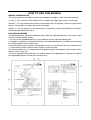
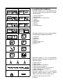
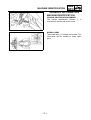
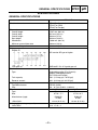
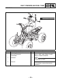
YFM80WP 4EM-AE1 SUPPLEMENTARY SERVICE MANUAL FOREWORD This Supplementary Service Manual has been prepared to introduce new service and new data for the YFM80WP. For complete information on service procedures, it is necessary to use this Supplementary Service Manual together with the following manual. YFM80(D) SERVICE MANUAL: 4EM-28197-20 YFM80WP SUPPLEMENTARY SERVICE MANUAL 2001 by Yamaha Motor Co., Ltd. First Edition, September 2001 All rights reserved. Any reproduction or unauthorized use without the written permission of Yamaha Motor Co., Ltd. is expressly prohibited. EB001000 NOTICE This manual was produced by the Yamaha Motor Company primarily for use by Yamaha dealers and their qualified mechanics. It is not possible to include all the knowledge of a mechanic in one manual, so it is assumed that anyone who uses this book to perform maintenance and repairs on Yamaha machine has a basic understanding of the mechanical ideas and the procedures of machine repair. Repairs attempted by anyone without this knowledge are likely to render the machine unsafe and unfit for use. Yamaha Motor Company, Ltd. is continually striving to improve all its models. Modifications and significant changes in specifications or procedures will be forwarded to all authorized Yamaha dealers and will appear in future editions of this manual where applicable. NOTE: Designs and specifications are subject to change without notice. IMPORTANT INFORMATION Particularly important information is distinguished in this manual by the following notations. The Safety Alert Symbol means ATTENTION! BECOME ALERT! YOUR SAFETY IS INVOLVED! WARNING CAUTION: NOTE: Failure to follow WARNING instructions could result in severe injury or death to the machine operator, a bystander or a person inspecting or repairing the machine. A CAUTION indicates special precautions that must be taken to avoid damage to the machine. A NOTE provides key information to make procedures easier or clearer. EB002000 HOW TO USE THIS MANUAL MANUAL ORGANIZATION This manual consists of chapters for the main categories of subjects. (See “Illustrated symbols”) 1st title 1: This is the title of the chapter with its symbol in the upper right corner of each page. 2nd title 2: This title indicates the section of the chapter and only appears on the first page of each section. It is located in the upper left corner of the page. 3rd title 3: This title indicates a sub-section that is followed by step-by-step procedures accompanied by corresponding illustrations. EXPLODED DIAGRAMS To help identify parts and clarify procedure steps, there are exploded diagrams at the start of each removal and disassembly section. 1. An easy-to-see exploded diagram 4 is provided for removal and disassembly jobs. 2. Numbers 5 are given in the order of the jobs in the exploded diagram. A number that is enclosed by a circle indicates a disassembly step. 3. An explanation of jobs and notes is presented in an easy-to-read way by the use of symbol marks 6. The meanings of the symbol marks are given on the next page. 4. A job instruction chart 7 accompanies the exploded diagram, providing the order of jobs, names of parts, notes in jobs, etc. 5. For jobs requiring more information, the step-by-step format supplements 8 are given in addition to the exploded diagram and the job instruction chart. 1 EB003000 2 GEN INFO ILLUSTRATED SYMBOLS Illustrated symbols 1 to 9 are printed on the top right of each page and indicate the subject of each chapter. SPEC 3 4 CHK ADJ 1 General information 2 Specifications 3 Periodic checks and adjustments 4 Engine 5 Carburetion 6 Drive train 7 Chassis 8 Electrical 9 Troubleshooting ENG 5 6 CARB DRIV 7 8 CHAS – ELEC + 0 Illustrated symbols 0 to F are used to identify the specifications appearing in the text. A B 0 Filling fluid A Lubricant B Special tool C Torque D Wear limit, clearance E Engine speed F Ω, V, A C D 9 TRBL SHTG T. R. E F G H G E J K B M L M M LS N Illustrated symbols G to M in the exploded diagrams indicate the types of lubricants and lubrication points. I S O LT New G Apply engine oil H Apply gear oil I Apply molybdenum disulfide oil J Apply wheel bearing grease K Apply lightweight lithium soap base grease L Apply molybdenum disulfide grease M Apply silicon grease Illustrated symbols N to O in the exploded diagrams indicate where to apply a locking agent N and when to install a new part O. N Apply the locking agent (LOCTITE) O Replace CONTENTS GENERAL INFORMATION ..............................................................................1 MACHINE IDENTIFICATION ....................................................................1 VEHICLE IDENTIFICATION NUMBER .................................................1 MODEL LABEL .....................................................................................1 SPECIFICATIONS ............................................................................................2 GENERAL SPECIFICATIONS ..................................................................2 MAINTENANCE SPECIFICATIONS .........................................................3 ENGINE ................................................................................................3 CHASSIS ..............................................................................................5 ELECTRICAL ........................................................................................5 CABLE ROUTING .....................................................................................7 PERIODIC CHECKS AND ADJUSTMENTS ..................................................11 INTRODUCTION .....................................................................................11 PERIODIC MAINTENANCE/LUBRICATION INTERVALS ......................11 SEAT, FENDERS AND FUEL TANK ......................................................12 SEAT AND FRONT PANEL ................................................................12 FRONT FENDER ................................................................................13 REAR FENDER ..................................................................................14 FUEL TANK ........................................................................................15 ENGINE ...................................................................................................16 SPEED LIMITER ADJUSTMENT ........................................................16 AIR FILTER CLEANING .....................................................................17 MACHINE IDENTIFICATION GEN INFO GENERAL INFORMATION MACHINE IDENTIFICATION VEHICLE IDENTIFICATION NUMBER The vehicle identification number 1 stamped into the left side of the frame. is MODEL LABEL The model label 1 is affixed to the frame. This information will be needed to order spare parts. –1– GENERAL SPECIFICATIONS SPEC SPECIFICATIONS GENERAL SPECIFICATIONS Model Model code number: Dimensions: Overall length Overall width Overall height Seat height Wheelbase Minimum ground clearance Minimum turning radius: Oil type or grade: Engine oil YFM80WP 5TH1 (For Oceania) 5TH2 (For CDN) 5TH3 (For Europe) 1,537 mm (60.5 in) 841 mm (33.1 in) 940 mm (37 in) 669 mm (26.3 in) 1,030 mm (40.6 in) 100 mm (3.9 in) 2,400 mm (94.5 in) API service SE type or higher Final gear oil Fuel: Type Tank capacity Reserve amount Spark plug: Type/Manufacturer Gap Tire: Type Size Manufacturer (type) <Wear limit> Indicator light wattage × quantity: “NEUTRAL” SAE 80API “GL-4” Hypoid gear oil Unleaded gasoline (For Oceania) Regular unleaded gasoline (For CDN and Europe) 6.8 L (1.5 Imp gal, 1.8 US gal) 0.9 L (0.2 Imp gal, 0.2 US gal) CR7HS (NGK) 0.6 ~ 0.7 mm (0.024 ~ 0.028 in) Front Rear Tubeless Tubeless AT18 × 7-7 AT18 × 8-7 DUNLOP DUNLOP KT586 KT587 <3 mm (0.12 in)> <3 mm (0.12 in)> 12 V 1.7 W × 1 –2– MAINTENANCE SPECIFICATIONS SPEC MAINTENANCE SPECIFICATIONS ENGINE Model YFM80WP Camshaft: Drive method Cam dimensions: Intake: Chain drive (Left) Exhaust: A “A” “B” “A” “B” 25.30 ~ 25.31 mm (0.996 ~ 0.997 in) 20.994 ~ 21.094 mm (0.827 ~ 0.831 in) 25.301 ~ 25.311 mm (0.996 ~ 0.997 in) 21.021 ~ 21.121 mm (0.828 ~ 0.832 in) B Camshaft runout limit Cam chain type/number of links Cam chain adjustment method Rocker arm/rocker arm shaft: Bearing inside diameter Shaft outside diameter Arm-to-shaft clearance <Limit> Valve spring: Free length: <0.03 mm (0.0012 in)> BUSH CHAIN/82 links Manual 10.000 ~ 10.015 mm (0.3937 ~ 0.3943 in) 9.981 ~ 9.991 mm (0.3930 ~ 0.3934 in) 0.009 ~ 0.034 mm (0.0004 ~ 0.0013 in) <0.08 mm (0.0032 in)> IN EX. <Limit> IN EX. Compressed length (valve closed): IN EX. Compressed spring force (installed): IN EX. <Tilt Limit> IN & EX. * 28.63 mm (1.13 in) 28.63 mm (1.13 in) <25.4 mm (1.00 in)> <25.4 mm (1.00 in)> 24.9 mm (0.980 in) 24.9 mm (0.980 in) 86.3 ~ 105.9 N (8.8 ~10.8 kgf) 86.3 ~ 105.9 N (8.8 ~10.8 kgf) <2.5° or 1.2 mm (0.047 in)> Direction of winding (top view): IN –3– EX MAINTENANCE SPECIFICATIONS Model YFM80WP Piston: Piston size “D” Measuring point “H” Piston over size: 2nd D 4th Offset Offset direction Piston clearance <Limit> Piston pin bore inside diameter Piston pin outside diameter Clutch: Friction plate: Thickness × Quantity <Wear limit> Clutch plate: Thickness × Quantity <Warp limit> Clutch spring: Free length × Quantity Clutch release method Clutch-in revolution Clutch-stall revolution Carburetor: Type/manufacturer/quantity I. D. mark Main jet Main air jet Jet needle-clip position Needle jet Cutaway Pilot jet Pilot outlet Pilot screw Valve seat Fuel level Float height Engine idling speed Intake vacuum SPEC 46.960 ~ 46.975 mm (1.8488 ~ 1.8494 in) 6.5 mm (0.256 in) (From bottom line of piston skirt) H 47.50 mm (1.870 in) 48.00 mm (1.890 in) 0.75 mm Intake side 0.025 ~ 0.045 mm (0.0010 ~ 0.0018 in) <0.15 mm (0.006 in)> 13.002 ~ 13.013 mm (0.5119 ~ 0.5123 in) 12.996 ~ 13.000 mm (0.5117 ~ 0.5118 in) 2.92 ~ 3.08 mm (0.115 ~ 0.121 in) × 6 <2.9 mm (0.114 in)> 1.2 ~ 1.6 mm (0.047 ~ 0.063 in) × 5 <0.06 mm (0.0024 in)> 28.3 mm (1.11 in) × 8 Inner push, cam push 2,100 ~ 2,300 r/min 2,800 ~ 3,000 r/min (M.J.) (M.A.J.) (J.N.) (N.J.) (C.A.) (P.J.) (P.O.) (P.S.) (V.S.) (F.L.) (F.H.) VM16SH/MIKUNI/1 5TH1 00 #76.3 ø1.2 3PZ 13-2 D-8M 3.5 #12.5 ø0.7 1-1/8 ø1.2 2.5 ~ 4.5 mm (0.10 ~ 0.18 in) Below carburetor body edge 20.0 ~ 22.0 mm (0.79 ~ 0.87 in) 1,750 ~ 1,850 r/min 36 kPa (270 mmHg) –4– MAINTENANCE SPECIFICATIONS SPEC CHASSIS Model YFM80WP Wheel: Front wheel type Rear wheel type Front rim size/material Rear rim size/material Rim runout limit: Vertical Lateral Brake lever & brake pedal: Brake lever free play (front brake) Brake lever free play (rear brake) Brake pedal free play Panel wheel Panel wheel 7 × 5.5 AT/steel 7 × 6.5 AT/steel <2.0 mm (0.08 in)> <2.0 mm (0.08 in)> 10 ~ 12 mm (0.4 ~ 0.5 in) at lever pivot 5 ~ 8 mm (0.20 ~ 0.31 in) at lever pivot 20 ~ 30 mm (0.8 ~ 1.2 in) ELECTRICAL Model YFM80WP CDI: Magneto model/manufacturer Pickup coil resistance (color) Source coil resistance (color) Lighting coil resistance (color) CDI unit model/manufacturer Ignition coil: Model/manufacturer Minimum spark gap Primary winding resistance Secondary winding resistance Rectifier/regulator: Type Model/manufacturer No load regulated voltage Capacity Withstand voltage F2FM/MORIC 264 ~ 396 Ω at 20°C (68°F) (W/L–W/R) 304 ~ 456 Ω at 20°C (68°F) (G/W–B/R) 0.72 ~ 1.08 Ω B–W 0.32 ~ 0.48 Ω B–Y/R 4EM/MORIC 2JN/MORIC 6 mm (0.24 in) 0.184 ~ 0.276 Ω at 20°C (68°F) 6.32 ~ 9.48 Ω at 20°C (68°F) (DC) (AC) (DC) (AC) Semi conductor-short circuit SH704-12/SHINDENGEN 14 ~ 15 V 13 ~ 14 V 5A 8A 200 V –5– MAINTENANCE SPECIFICATIONS Model Electric starter system: Type Starter motor: Model/manufacturer Out put Armature coil resistance Brush: Overall length <Limit> Spring pressure Commutator: Diameter <Wear limit> Mica undercut Starter relay: Model/manufacturer Amperage rating Coil winding resistance Starting circuit cut-off relay: Model/manufacturer Coil winding resistance Diode Circuit breaker: Type Amperage for individual circuit/quantity: Main Reserve SPEC YFM80WP Constant mesh type ADB4A5/DENSO 0.2 kW 0.0288 ~ 0.0352 Ω at 20°C (68°F) 6 mm (0.24 in) <3.5 mm (0.14 in)> 3.24 ~ 4.22 N (330 ~ 430 gf) 16.5 mm (0.65 in) <15.5 mm (0.61 in)> 1.0 mm (0.04 in) MS5D-611/JIDECO 100A 3.87 ~ 4.73 Ω at 20°C (68°F) ACA12115-3/MATSUSHITA 72 ~ 88 Ω at 20°C (68°F) Yes Fuse 5A×1 5A×1 –6– CABLE ROUTING SPEC CABLE ROUTING 1 Throttle cable 2 Fuel tank breather hose 3 Carburetor ventilation hose 4 Final gear case breather hose 5 Crankcase breather hose 6 Fuel hose 7 Band 8 Starter relay 9 Starting circuit cut-off relay 0 Rectifier/regulator A Battery breather hose B CDI magneto lead C Carburetor overflow hose D Front brake cable (right) E Front brake cable (left) È Pass the final gear case breather hose through the guide. É Pass the battery breather hose through the hole. –7– CABLE ROUTING 1 Rear brake cable 2 Band 3 Wireharness 4 Ignition coil 5 Handlebar switch lead 6 Rear brake switch lead 7 “NEUTRAL” indicator light lead 8 Main switch 9 CDI unit 0 Fuel hose A Front brake cable B Fuel tank breather hose C Throttle cable –8– SPEC CABLE ROUTING 1 Fuel tank breather hose 2 Throttle cable 3 Front brake cable (left) 4 Front brake cable (right) 5 Air filter joint 6 Rear brake switch lead 7 Handlebar switch lead 8 “NEUTRAL” indicator light lead 9 Rear brake cable –9– SPEC CABLE ROUTING 1 Front brake cable 2 Throttle cable 3 Fuel tank breather hose 4 Battery negative lead 5 Fuse 6 Battery positive lead 7 Band 8 Handlebar switch 9 Rear brake switch 0 Rear brake cable SPEC È Pass the leads through the hole. – 10 – INTRODUCTION/PERIODIC MAINTENANCE/ LUBRICATION INTERVALS CHK ADJ EB300000 PERIODIC CHECKS AND ADJUSTMENTS INTRODUCTION This chapter includes all information necessary to perform recommended inspections and adjustments. These preventive maintenance procedures, if followed, will ensure more reliable vehicle operation and a longer service life. The need for costly overhaul work will be greatly reduced. This information applies to vehicles already in service as well as to new vehicles that are being prepared for sale. All service technicians should be familiar with this entire chapter. EB301000 PERIODIC MAINTENANCE/LUBRICATION INTERVALS INITIAL ITEM ROUTINE 1 month Valves* • Check valve clearance. • Adjust if necessary. Cam chain* • Check chain tension. • Adjust if necessary. Spark plug • Check condition. • Adjust gap and clean. • Replace if necessary. Air filter element • Clean. • Replace if necessary. Carburetor* • Check idle speed/choke lever operation. • Adjust if necessary. Crankcase breather system* • Check breather hose for cracks or damage. • Replace if necessary. Exhaust system* • Check for leakage. • Retighten if necessary. • Replace gasket if necessary. Fuel line* • Check fuel hose for cracks or damage. • Replace if necessary. Engine oil • Replace (warm engine before draining). Final gear oil • Check oil level/oil leakage. • Replace every 12 months. Brakes* • Check operation. • Adjust if necessary. Clutch* • Check operation. • Adjust if necessary. Wheels* • Check balance/damage/runout. • Replace if necessary. Wheel bearings* • Check bearing assemblies for looseness/damage. • Replace if damaged. Steering system* • • • • Knuckle shafts/ steering shaft* • Lubricate every 6 months.** Fittings and fasteners* • Check all chassis fittings and fasteners. • Correct if necessary. Battery* • Check specific gravity. • Check breather hose for correct routing. • Correct if necessary. 3 months EVERY 6 months 6 months Every 20 ~ 40 hours (more often in wet or dusty areas.) Check operation. Repair if damaged. Check toe-in. Adjust if necessary. * It is recommended that these items be serviced by a Yamaha dealer. ** Lithium-soap-based grease. – 11 – 1 year SEAT, FENDERS AND FUEL TANK CHK ADJ SEAT, FENDERS AND FUEL TANK SEAT AND FRONT PANEL 1 3 4 5 2 Order 1 Job name/Part name Removing the seat and front panel Seat 2 3 4 5 Front panel Fuel tank breather hose Handlebar cover Neutral indicator light leads Q’ty 1 1 1 1 2 – 12 – Remarks Remove the parts in the order below. NOTE: Pull back the seat lock lever, than pull up on the rear of the seat. Disconnect For installation, reverse the removal procedure. SEAT, FENDERS AND FUEL TANK CHK ADJ FRONT FENDER 1 4 2 T. R. Order 1 2 3 4 7 Nm (0.7 m • kg, 5.1 ft • Ib) 3 Job name/Part name Removing the front fender Seat and front panel Fuel tank top panel Air cleaner joint clamp screw Main switch Front fender Q’ty 1 1 1 1 Remarks Remove the parts in the order below. Refer to “SEAT AND FRONT PANEL”. Loosen For installation, reverse the removal procedure. – 13 – CHK ADJ SEAT, FENDERS AND FUEL TANK REAR FENDER T. T. R. R. 7 Nm (0.7 m • kg, 5.1 ft • Ib) 7 Nm (0.7 m • kg, 5.1 ft • Ib) 3 1 5 6 4 2 3 Order 1 2 3 Job name/Part name Removing the rear fender Seat Front fender Battery band Main fuse Battery lead Q’ty 1 1 2 Remarks Remove the parts in the order below. Refer to “SEAT AND FRONT PANEL”. Refer to “FRONT FENDER”. Disconnect. CAUTION: First disconnect the negative lead, then disconnect the positive lead. 4 5 6 Battery breather hose Battery Rear fender 1 1 1 For installation, reverse the removal procedure. – 14 – SEAT, FENDERS AND FUEL TANK CHK ADJ FUEL TANK 2 T. R. 10 Nm (1.0 m • kg, 7.2 ft • Ib) 1 Order 1 Job name/Part name Removing the fuel tank Seat and front panel Front fender Fuel hose 2 Fuel tank Q’ty 1 Remarks Remove the parts in the order below. Refer to “SEAT AND FRONT PANEL”. Refer to “FRONT FENDER”. NOTE: Before disconnecting the fuel hose, turn the fuel cock to “OFF”. 1 For installation, reverse the removal procedure. – 15 – SPEED LIMITER ADJUSTMENT CHK ADJ ENGINE SPEED LIMITER ADJUSTMENT The speed limiter keeps the carburetor throttle from becoming fully-opened even when the throttle lever is applied to the maximum position. Screwing in the adjuster stops the engine speed from increasing. 1.Check: ● Speed limiter length a Out of specification → Adjust. a Speed limiter length: Less than 20 mm (0.8 in) 2.Adjust: ● Speed limiter length *********************************************** Speed limiter length adjustment steps: ● Loosen the locknut 1. ● Turn the adjuster 2 in or out until the specified speed limiter length is obtained. 1 2 Turning in Speed limiter length is decreased. Turning out Speed limiter length is increased. ● Tighten the locknut. WARNING ● ● Particularly for a beginner rider, the speed limiter should be screwed in completely. Screw it out little by little as their riding technique improves. Never remove the speed limiter for a beginning rider. For proper throttle lever operation do not turn out the adjuster more than 20 mm (0.8 in). Also, always adjust the throttle lever free play to 3 ~ 5 mm (0.12 ~ 0.20 in). *********************************************** – 16 – SPEED LIMITER ADJUSTMENT/ AIR FILTER CLEANING ● 1 CHK ADJ Air intake restrictor plate removal Refer to “AIR FILTER CLEANING”. NOTE: To obtain full engine performance capability, removing the air intake restrictor plate 1 is required. Since removal of this plate will result in a significant increase in power, turn the speed limiter completely back in again. AIR FILTER CLEANING NOTE: There is check hose 1 at the bottom of the air filter case. If dust and/or water collects in this hose, clean the air filter element and air filter case. 1 1.Remove: ● Front panel Refer to “SEAT, FENDERS AND FUEL TANK”. 2.Remove: ● Air filter cover 1 1 4 3 3.Remove: ● Rubber band 2 4.Pull out the air filter element assembly. 5.Remove: ● Guide ● Air filter element 3 ● Air intake restrictor plate 4 2 CAUTION: The engine should never be run without the air filter element; excessive piston and/or cylinder wear may result. – 17 – AIR FILTER CLEANING CHK ADJ 6.Check: ● Air filter element Damage → Replace. 7.Clean: Air filter element ● *********************************************** Cleaning steps: ● Wash the element gently, but thoroughly in solvent. WARNING Never use low flash point solvents such as gasoline to clean the air filter element. Such solvent may lead to a fire or explosion. ● Squeeze the excess solvent out of the element and let dry. CAUTION: Do not twist the filter element when squeezing the filter element. ● Apply the engine oil. out the excess oil. ● Squeeze NOTE: The element should be wet but not dripping. *********************************************** 8.Install: ● Air filter element NOTE: Make sure its sealing surface matches the sealing surface of the case so there is no air leak. – 18 –