1
EDK GENERIC
TUTORIAL MANUAL
FOR HITACHI ON-CHIP FLASH MICROCONTROLLERS
Cautions
1.
This document may be, wholly or partially, subject to change without notice.
2.
All rights reserved. No one is permitted to reproduce or duplicate, in any form, a part or this entire
document without Hitachi Micro Systems Europe Limited's written permission.
Trademarks
General
All brand or product names used in this manual are trademarks or registered trademarks of their respective
companies or organisations.
Specific
Microsoft, MS and MS-DOS are registered trademarks and Windows and Windows NT are
trademarks of Microsoft Corporation.
Document Information
Product Code:
D003959_11
Version:
4
Date:
28/10/2002
Copyright © Hitachi Micro Systems Europe Ltd. 1995-2002. All rights reserved.
Global:
http://www.hitachisemiconductor.com
http://www.hmse.com
2
1.
TABLE OF CONTENTS
1.
TABLE OF CONTENTS ............................................................................................................................................. 3
2.
GLOSSARY OF TERMS ............................................................................................................................................ 4
3.
INTRODUCTION ....................................................................................................................................................... 5
4.
TUTORIAL PROJECT WORKSPACE........................................................................................................................... 6
5.
DEBUG_WITH_HMON BUILD ................................................................................................................................. 7
5.1. CREATING A NEW PROJECT WORKSPACE.................................................................................................... 8
5.2. INTERRUPTS ...................................................................................................................................................... 8
5.3. WHAT THE STARTUP CODE DOES .................................................................................................................. 9
5.4. BUILDING CODE & PROGRAMMING THE FLASH.......................................................................................... 10
5.5. RUNNING THE DEBUG TUTORIAL ................................................................................................................. 10
6.
RELEASE BUILD ................................................................................................................................................... 15
6.1. VECTOR TABLE WITHOUT HMON:................................................................................................................. 15
6.2. LOW LEVEL INITIALISATION ........................................................................................................................... 16
6.3. THE SERIAL I/O FUNCTIONS: ......................................................................................................................... 16
6.4. LINKING FOR STANDALONE CODE ............................................................................................................... 17
6.5. RUNNING THE CODE....................................................................................................................................... 17
3
2.
GLOSSARY OF TERMS
HEW
Hitachi Embedded Workshop
CCR
Condition Code Register
EXR
EXtended control Register
SR
Status Register
ISR
Interrupt Service Routine
PWM
Pulse Width Modulation
CPU
Central Processing Unit
PC
Program Counter
IRQ
Interrupt ReQuest
NMI
Non-Maskable Interrupt
RTE
ReTurn from Exception
LED
Light Emitting Diode
4
3.
INTRODUCTION
This manual is designed to answer, in tutorial form, the most common questions asked about using an Evaluation
Development Kit: The tutorials help explain the following:
•
How do I compile, link, download, and run a simple program on the EDK?
•
How do I build an embedded application?
•
How do I use Hitachi’s tools?
The project generator will create a tutorial project with two selectable build configurations
•
Debug_with_HMON is a project built with the Hitachi Configurable monitor (HMON).
•
Release build demonstrating use without the embedded Monitor.
Files referred to in this manual are installed using the project generator as you work through the tutorials. The tutorial
examples in this manual assume that installation procedures described in the EDK Quickstart Guide have been
completed. Please refer to the quickstart guide for details of downloading the Hitachi Debugging Monitor to the
board.
The source code referred to in this manual is for example purposes only. Due to software revisions, the code may not
accurately reflect the supplied code. Tutorials are for Hitachi toolchains only.
NOTE: These tutorials are designed to show you how to use the EDK, and are not intended as a
comprehensive introduction to HMON, Hitachi Embedded Workshop (HEW) or the compiler toolchains –
please consult the relevant user manuals for more in-depth information.
5
4.
TUTORIAL PROJECT WORKSPACE
The workspace includes all of the files for both of the build configurations. The tutorial code is common to both the
Debug_with_HMON and the Release build configurations. The workspace is designed to show how code can be
written, debugged then downloaded without the debug monitor in a ‘Release’ situation.
The build configuration menu in HEW allows the project to be configured such that certain files may be excluded from
each of the build configurations. This allows the inclusion of the debug monitor within the debug build, and it’s
exclusion in the Release build. Contents of common C files are controlled with the defines set up in the build
configurations and #ifdef statements within the files.
Maintaining only one set of project files means that projects are more controllable.
The HMON Monitor code is provided in a pre-compiled library for inclusion in the users code. This library bust be
included in the tool chain linker settings. There are some configuration options provided to the user. These are
provided in the hmonserialconfiguser.c file and the referenced hmonserialconfiguser.h and hmonserialstruct.h More
information on this is provided later in the Tutorial Manual.
Certain files have different functionality depending on the build configuration. These differences are covered in
further detail within the chapters about these build configurations. However an example is that the part of the
program which, in Release mode, would output text to a serial teminal, is excluded from the debug build with an ifdef
statement because the debugger uses the serial port.
6
5.
DEBUG_WITH_HMON BUILD
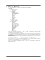
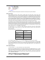
The Debug_with_HMON Build Configuration should look like the workspace below.
In the Debug_with_HMON configuration the file SCI.C is excluded. This is because in debug mode HEW
communicates with the monitor using the serial port.
The structure definition and assignment has already been done, to make it easy to access the on-chip peripheral
control registers for all the device’s peripheral registers. The code for this is in a header file called iodefine.h. This
file is created when you generate a new project in HEW. So for this tutorial example all we have to do is include the
header file in our C file:
#include “iodefine.h”
/* register definition header file */
With this file included, any structure or assignment declared, can be used in our C program. Note that each separate
C file that uses any of these definitions must #include the header file in it.
Please refer to the main.c and hwsetup.c source files for the function “HardwareSetup()” for specific on-chip
peripheral settings, etc.
7
5.1. CREATING A NEW PROJECT WORKSPACE
To look at the program start Hitachi Embedded Workshop from the Windows Start Menu or from its icon:
•
Open a new tutorial workspace from the ‘File | New Workspace…’ menu or select ‘Create a new project
workspace if you are presented with the ‘Welcome!’ dialog.
•
Enter a name for the workspace “EDK_Tutorial “
•
The project name field will be pre-filled to match the workspace name above; you may change this name.
•
Select the CPU family and Toolchain for the EDK
•
Select the EDK Project type for your EDK.
•
Click OK to start the EDK Project Generator wizard.
•
Select “Tutorial” as the type of project to generate and then click “Next”.
•
Click “Finish” to create the project
The project generator wizard will display a confirmation dialog. Press ‘OK’ to create the project and insert the
necessary files.
You will see a tree display showing all the files in this project.
•
To view the file main.c double click on the file in the Workspace window. A new window will open showing the
code.
5.2. INTERRUPTS
Interrupts are used within the tutorial. General usage and the interaction with HMON is explained in the following
sections. It is advisable that this section is read in detail to ensure any future Project Workspaces created by the user
are sufficient for use with HMON, additionally the HMON User manual should be referred to for implementation
details.
8
5.2.1. INTERRUPT OVERVIEW
In most user applications the rapid response of the system to external stimuli is essential, in such systems the CPU
must be informed of the change in the system status immediately. To rely on polled tests of the various peripheral
control registers represents a large CPU overhead. Hitachi microcontrollers support a wide range of on-chip
peripherals; each being capable of generating at least one CPU interrupt. In addition the CPU may be signalled from
external devices using the NMI or one of the IRQ interrupt signals. In the debug tutorial the compare/match interrupt
of the PWM Timer is used to vary the duty cycle of the flashing LED.
Microcontroller architectures provide direct hardware support for interrupts, via the interrupt controller. Each interrupt
source is allocated a special vector address. The vector address is used to store the address of the interrupt service
routine (ISR), which is to be executed when the relevant interrupt is accepted. The interrupt controller tests the
priority level of an incoming interrupt against the priority level that the CPU will currently accept. If the incoming
interrupt is higher than the current CPU mask interrupt mask level, then interrupt processing begins. The program
counter (PC) and the CCR / EXR / SR are stacked (processor dependant), and the PC set to the value contained in
the relevant vector address. Execution then continues from the new PC value. The ISR should be terminated with a
return from exception (RTE) instruction to ensure that the PC and the status/condition are correctly restored on exit.
5.2.2. CREATION OF AN ISR IN C
It is often desirable to write all your application code in C, where possible. The Hitachi tools support extensions to the
ANSI C language to allow interrupt service routines (ISR) to be written. As mentioned above an ISR is distinguished
from a normal function by the fact that it is terminated using an RTE instruction. However, this is not the only
difference. ISRs are by nature asynchronous and thus you cannot rely on the state of the registers on entry to the
function. In addition the ISR must preserve the state of all registers, as there is no way of telling which registers were
currently in use by the CPU when the exception occurred.
You also need to create an entry in the vector table that gives the address of the ISR for the given interrupt. Each
vector is located at a fixed address, so care must be taken to place it correctly. To define a function as an ISR, simply
precede it by either of the following forms of statement:
#pragma interrupt (Interrupt function declaration)
__interrupt (vect=x) : Where x is the vector number of the interrupt you wish to reference.
This instructs the compiler to treat the function as an ISR, and hence to preserve the register values, and to
terminate with an RTE instruction. When the interrupt occurs the corresponding ISR function address is fetched from
the vector table and the program will jump to that address. Therefore the address of the specific ISR needs to be
stored in the correct place in the vector table. When you create a new project in HEW, the file defining the vector
table and ISRs is intprg.c.
intprg.c contains default ISR functions for all interrupts. Those used by HMON are excluded from the
Debug_with_HMON build using #ifdef statements. The interrupt used by the tutorial code is defined and contained at
the bottom of the main.c file, and commented out of intprg.c.
5.2.3. HMON AND USER INTERRUPTS
When using HMON to debug code, certain interrupts are reserved for use by the Monitor.
These are, the TRAP INTERRUPTS, the PC BREAK (when available), and those for the serial port used to connect
to HEW. The vectors for these are provided in vectors.src Refer the HMON User Manual, this details the interrupts
used by HMON and user considerations to ensure correct operation.
5.3. WHAT THE STARTUP CODE DOES
The start up code will perform initialisation depending on the device used on your EDK. The start up routine differs
between SH, H8 and H8S devices. Review the startup source code before reading the next sections.
The initialisation process can be viewed in the PowerON_Reset() function in the project file resetprg.c. This functon
is declared as the entry point of the system using the “entry” #pragma, this tells the compiler to insert assembly code
at the beginning of the function to set up the stack pointer using the section name S and the stack size stored in
stacksct.h
The microcontroller reset vector (Vector 0) is used by HMON. This allows HMON to start first and initialise from
power on reset. When using the Release build configuration the entry point is defined in resetprg.c
9
The ‘Run | Reset CPU’
and ‘Run | Go Reset’
functionality is determined by configuring the monitor code
and the User_Vectors section in the Linker Settings. The User_Vectors section is a pointer to a location pointing to
the start address of the tutorial code. Its location in the linker section corresponds to the pre-defined value in the file
resetprg.c This pointer location is fixed in the HMON library and must not be changed. Review the debug build linker
sections to determine its value.
The pointer allows the monitor to set the PC to the address in memory of the start of the program code when either
‘Run | Reset CPU’
and ‘Run | Go Reset’
is pressed.
The operations performed by the startup code are:
•
Unmask all interrupts.
•
Set the stack pointer to a valid address.
•
Set the initialised static variables to the correct values.
•
Set all other static variables to 0 (see statics text for details).
•
Call the hardware initialisation code.
•
Call the main routine.
Finally the PowerON_Reset() function ends with a sleep() intrinsic function call to put the microcontroller into a safe
state and avoid code run-away.
5.4. BUILDING CODE & PROGRAMMING THE FLASH
Now armed with the knowledge of what is happening in the “background”, the Debug_with_HMON project will need
to be flashed into the microcontroller on the EDK to allow you to debug code.
Until this file is flashed onto the microcontroller no debug can be performed.
Please refer to the Quickstart guide for details of programming the EDK with the Debug Project containing the HMON
monitor
5.5. RUNNING THE DEBUG TUTORIAL
Once you have built your code in HEW as detailed in the Quickstart guide, the file <projectname>.abs is created.
•
To download the code on to the EDK, Right Click on the download module and choose “Download module” from
the pop-up menu.
•
To view the code, double click on the source code file resetprg.c in the project workspace window.
A window appears showing the C source code.
•
Click on the “ResetCPU” button,
•
The Program Counter will go to the program start address, denoted by a yellow arrow.
.
10
Place a breakpoint next to the main() function by double left clicking the mouse in the breakpoint column.
Then press ‘Debug | Go’
.
This command will enable us to start running our code from main, and will also have initialised the hardware.
To execute the first line of the program, select ‘Step in’ to step into the main function using one of the methods listed
below.
There are three ways to step / run through the tests
1)
Step over for the next line and continue this process to ‘step over’ the individual tests one at a time, or
2)
Step in to Step in to the individual tests, or
3)
Go and the program will run from where the PC is currently until it meets a breakpoint.
Function
Menu Command:
Accelerator
Step in
Debug | Step in
F11
Step over
Debug | Step over
F10
Step out
Debug | Step out
Shift + F11
Go
Debug | Go
F5
Toolbar Button
5.5.1. LED TEST
This test code allows the user to flash ON/OFF the on-board LED while stepping through the code within HDI.
Set a breakpoint at the line where the state of the LED port pin data register bit is toggled, as shown.
Choose ‘Run’ to run to the breakpoint. Choosing ‘Go’ again will toggle the state of the LED. ‘Go’ again a couple more
times to observe the LED change state, then double click the breakpoint to remove it. Place a breakpoint at the call
for the next function in Main(), the Statics Test; and press ‘Go’.
11
The LED should flash the remaining number of times left in the FOR loop and stop at the breakpoint.
5.5.2. STATICS TEST
Most C applications will have a certain number of variables which are of either global or module scope. These
variables are referred to as ‘static’, as they require statically allocated (i.e. build at a time) space. Static variables may
be of any valid type and may, or may not, be given an initial value. In an embedded system the code is resident in
some form of non-volatile memory (ROM, Flash), and the application must boot from an uninitialised state at powerup. In such systems the static data must be set to its initial value before the user’s application code is called (i.e.
before the main() executes). In addition it is common for the applications data area to be located in some form of
memory which requires the system hardware to be initialised before it can be accessed e.g. RAM. These systems
require startup code to perform the initialisation from reset, and then to pass execution to the user code.
The information on how to initialise the static areas must be stored in non-volatile memory (i.e. ROM), so that the
startup code knows what to do. However the most desirable situation is one where the user can happily forget about
the startup because initialisation information is automatically created and referenced using the compiler build tools.
This is the goal of the Statics test within the Debug_with_HMON tutorial, to demonstrate that this code has indeed
worked. This test must be run under HMON to verify the results.
The character string ucStr[]is defined as a global variable with an initial value of ”hello world”. Global variables
are static by definition, however variables can use static memory allocation by using the ‘static’ compiler directive
before its declaration.
By default the sections have the following names:
ANSI C Section
Hitachi Compiler/Linker
section name
Program
P
Constants
C
Initialised Data
D
Un-initialised Data
B
RAM
R
The un-initialised unsigned integer uiCount is in section B (RAM) and is initialised to zero by _INITSCT.
The code in _INITSCT copies the initial value of ucStr[] in ROM to RAM. The initial value is in section D (ROM)
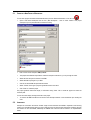
and is copied to R (RAM), this can be seen in the Link/Library tab of the ‘Options|Toolchain’ menu in HEW. Select
Output from the top drop down list and ‘Show entries for’ ROM to RAM mapped sections. This is referenced in the
source file dbsct.c.
5.5.3. VIEWING VARIABLES
To view the variable ucStr open a watch window ‘View | Watch’ within HEW.
Place the cursor in the Watch window, then use the right mouse button and click ‘Add watch’. Enter ‘ucStr’ as the
name of the variable in the field and click OK. The variable will be added to the watch window. Another method of
adding a watch is to right click on the variable in question and choose ‘instant watch’. This opens up an instant watch
window. Clicking ‘Add’ adds the variable to the watch window. The watch window shows that, before the statics test,
ucStr has the value “hello world”.
12
‘Step In’ repeatedly, and in the Watch window you will see that the contents of the variable ucStr is overwritten with
the data “abcdefghijk”.
The address shown above may differ on your EDK, however the string value will match.
5.5.4. TIMER PERIPHERAL
The microcontroller contains a lot more than simply a CPU. A whole host of peripherals are available to you for use in
a target application. Each peripheral module has a set of control and status registers, which act as the interface to
the CPU, Many peripherals also have pins associated with them, which act as the interface to the outside world.
Each peripheral can signal a change in its status by setting bits in one of its registers, or by sending an interrupt to
the CPU, prompting immediate action.
The control and status registers of the peripheral modules are memory mapped, each one having a unique address
at the top of the address space. Registers vary in type from byte wide to long word wide and from read/write to read
or write only. To allow simple access to the registers the flexible casting feature of C may be used. In this tutorial a
symbol can be defined which corresponds to the access inside the address of the given register. This requires the
address, which is a constant integer value, to be treated as an address reference (i.e. a pointer), and then pointer
indirection to be used to access the contents of the address. To further complicate matters, the entire construct must
be declared as ‘volatile’ to stop the C compiler from optimising away accesses to the register. This is because the
registers may be modified by some operation other than one performed by the CPU, and thus the compiler can have
no visibility of this. Optimising compilers often remove accesses to what appears to be redundant information – this
must be stopped in the case of peripheral control and status registers, hence the use of the ‘volatile’ keyword.
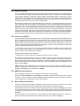
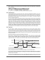
5.5.5. TIMER CODE
The Timer program is designed to flash an LED on the EDK using one of the on-chip timer modules, instead of
software. The timer is used to output a PWM square wave signal on the timer output that is multiplexed with a port
pin on the microcontroller, to which one of the LEDs on the EDK is connected. The port and the timer output both
share this pin, but cannot share it at the same time. The cycle period for the waveform is set by the value in one of
the timer’s Timer General Registers (TGRx) and the duty cycle is set by the value in another TGRx register using an
Interrupt Service Routine.
We will assume TGRA for the cycle period and TGRB for the duty cycle.
When the timer is enabled the timer will start counting up. When the value in the timer count (TCNT) register
matches the value in the (TGRB) register, the output of the pin will go to 1 turning the LED on, and the counter will
continue to increment. When the value in the TCNT register matches the value in the (TGRA) register the TCNT
register will be reset to zero, causing the cycle to reset and the output of the pin to be cleared turning the LED off.
TGRA
TGRB
0
time
Timer Pin O/P
The function HardwareSetup( ) sets up the control registers in the timer module. In order for it to be called we must
ensure the function is called at the start of resetprg.c
main( ) calls the timer test function in which the duty cycle register is set up and the timer started.
The timer interrupt function is the interrupt service routine used when the timer compare match occurs. The first line
clears the timer’s compare/match interrupt bit, if the interrupt is not cleared, another interrupt will immediately be
generated on return from the ISR.
The second line in the ISR decrements the duty value in the TGRB compare register to shorten the ‘off’ time of the
LED, when it is decremented past 0 the value in the register will underflow and start again at a high value i.e. with a
13
short pulse on the LED. Note that we decrement the value rather than increment it, because if we incremented then
very shortly after returning from the interrupt, we would get a compare/match on this larger value (as the timer is still
counting) rather than waiting until another complete cycle period has been completed.
The startup function HardwareSetup() in hwsetup.c has code to enable the Timer module compare/match interrupt:
TIMER_TCR = SETUP_TCR;
This causes an interrupt to occur whenever the value in the TCNT register matches that in the TGRB register. The
special function set_imask(0) or set_imask_ccr(0) or set_imask_exr(0) is added, this is an in-line function to insert an
instruction to unmask the interrupts. This allows HMON to utilise the interrupts while stepping the code.
In order to use this special function we have to include the header file machine.h. This contains a number of
functions definitions to allow access to CPU operations like accessing the CCR / SR and using specific instructions
e.g. trapa, sleep, movfpe, eepmov, mac, rotlw, dsub, nop. These functions may be used in an application to gain
access to the CPU, they should be used with care as they directly control the underlying hardware and are not
subject to checking by the compiler.
5.5.6. RUNNING THE TIMER
Open a code window with the main() function and set a breakpoint at the start of the timer function,
Press ‘Go’ or ‘Go Reset’ and the program should stop at the breakpoint. This instruction will have set up the registers
for the Timer peripheral to the necessary values for running the timer.
Next use ‘Debug | Step In’. This will step into the timer function.
Set a breakpoint in the interrupt routine where the duty cycle is changed and ‘Go’ to the breakpoint. The line should
look like this:
‘You should be able to see the LED flash with 50% duty.
•
Run to the breakpoint using ‘Run | Go’ again
You can see the duty value change and the corresponding flash period of the LED also change.
Note that when the program is stopped the duty value does not change even though the LED continues to flash
and compare/match occurs as the timer continues to run. Although this does in fact cause an interrupt request,
HMON masks interrupts while the program is stopped.
•
Remove the breakpoint and Go
You cannot see the Timer register value decrement while the program is running, however you can see the duty
value of the LED flash change.
14
6.
RELEASE BUILD
This tutorial includes the three tests from the debug tutorial (Flashing LED, Statics Test, and Timer Test). This tutorial
shows how to run the code on the EDK without the debug monitor. The aim of this example is to show that an
application can be created using these tools which will be capable of running ‘stand-alone’. The majority of the work
has already been done. This example uses the same source files that were used in the Debug Tutorial. The main
difference is that since HMON will not be resident, a real power-on reset vector must be created and not one that
calls HMON initialisation function. Since HMON is no longer using the UART serial interface this is now available to
our application, hence in this build the source code for the serial port is included. This is now used to output a test
menu to an external terminal application. This allows the user to select between the tests, which run individually.
6.1. VECTOR TABLE WITHOUT HMON:
Change the session menu from ‘SessionH8S_2000_HMON’ to ‘DefaultSession’.
When prompted to save the session, choose Yes.
Now change the build configuration from ‘HMON_Debug’ to ‘Release’.
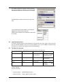
The project workspace now shows the HMON files excluded and the serial port functions included.
15
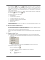
The ‘Release’ configuration replaces the define for the debug
build. The project build now includes the code contained in the
‘#ifdef Release’ statements, as the serial port is now available.
The HMON library has been removed from the ‘Input’ of the
linker
If you examine the linker section settings, you’ll see that the
HMON specific sections have been removed.
(Note the section addresses may be different from those shown
for your EDK)
6.2. LOW LEVEL INITIALISATION
As we saw in the debug tutorial, low level initialisation occurs before the user’s code is called in order to set up the
CPU and essential peripherals. Since we are running standalone we do not use HMON to initialise the EDK
environment for us. Therefore we must do it ourselves in HardwareSetup().
6.3. THE SERIAL I/O FUNCTIONS:
SCI.c and SCI.h are the files containing the four serial functions shown in the table below:
Function
Returns
Arguments
Description
InitSCI
Unsigned char (UINT8)
Struct
Initialises serial port
using data in structure
and returns error flags
SCI_Init_Params
GetChar
Unsigned char (UINT8)
Void
Returns a character
received by SCI
PutChar
Void
Unsigned char
Transmits a character
PutStr
Void
Unsigned char *
Transmits a string of
characters
(null
terminated)
This is example code for control of the SCI port. The initialisation function takes a structure containing four variables
set in SCI_Init_Data:
struct SCI_Init_Params
{
unsigned char Baud;
/* Baud Rate Register Value */
unsigned char Parity; /* Parity P_NONE, P_EVEN, P_ODD */
16
unsigned char Stops; /* Number of stop bits 1,2 */
unsigned char Length; /* Length of byte transmitted 7,8 */
};
struct SCI_Init_Params SCI_Init_Data={B115200, P_NONE, 1, 8};
B115200 is a macro defining the BRR register value to set the serial port speed to 115200 bits per second.
6.4. LINKING FOR STANDALONE CODE
Now we need to program the absolute file into the Flash memory, we want an S-Record format output rather than a
Elf/Dwarf debug file, the build process includes a final build phase that creates a .mot s-record file from the .abs file.
Also debug information is of no use to us, by default the output format for the “Release” build configuration is to not
include debug information in the output file.
•
You can inspect these options in the Output options of the Linker dialog.
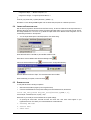
Press the BOOT button on the EDK, to place the EDK into Boot mode.
Select “Boot” from the HMON FLASH Download Settings button,
Click on the “Download Device Image”
.
, and browse to the “Configuration Directory”
Select the Release mot file and “Open”. This will download the file to the EDK.
When downloading is complete, choose disconnect,
.
6.5. RUNNING THE CODE
To verify that the tutorial is working as expected:
•
Start a terminal emulation program (such as HyperTerminal).
•
Connect to the EDK with the correct protocol settings set in the Release tutorial, the structure
struct SCI_Init_Params SCI_Init_Data={B115200,P_NONE,1,8};
in this example 115200 baud, 8 bit, no parity, 1 stop.
Please refer to your serial port comms definition file for specific settings.
•
On pressing the reset button, the EDK will enter user mode and a test menu should appear on your
hyperterminal screen. This allows you to select between the 3 individual tests:
1. Flashing LED Test
2. Statics Test
3. Timer Test.
17
Choose an option and view the test running on the EDK. The Flashing LED will flash one LED On/Off for a few
seconds. The Statics test will output a string of characters, and the Timer test will flash the other LED.
18