1
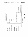
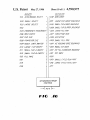
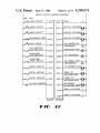
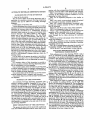
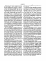
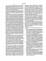
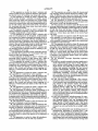
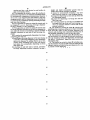
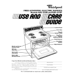
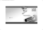
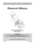
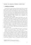
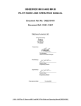
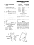
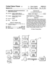
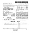
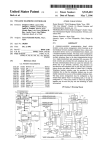
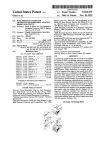
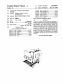
I
United States Patent [19]
[11] Patent Number:
Credle, Jr.
[45]
[54]
Date of Patent:
4,590,975
May 27, 1986
AUTOMATIC BEVERAGE DISPENSING
3,951,303
9/1973 Hobden et a1. ..................... .. 221/96
SYSTEM
4,102,660
8/1976
Beckett et a1. . . . . . .
4,174,742 11/1979 Murphey et a1.
[75]
Inventor:
William S. Credle, Jr., Stone
4,198,831
Mountain, Ga.
4,228,923
8/1979
Barnard ..... ..
The (ma-C01“ Cmnpany, Atlanta»
4,241,847 12/1978 Lancia et a1.
Ga-
4,3l9,441 11/1980
[21] APPI- N04 620,192
[22] Filed:
Jun, 13, 1984
[5
141/174
1/1978 Barnard ................... .. 62/320
4,226,269 12/1978 Carr et a1. ......................... .. 222/361
,
[73] Asslgne°=
. . . . .. 62/344
.. 222/52
.. 221/12
Credle ................................. .. 53/131
Primary Examiner—Houston S. Bell, Jr.
[57]
ABSTRACT
Illt. Cl.‘ .............................................. ..
3/04
U.S. Cl. ...... ..‘ ................................ ..
A narrow, modular automatic beverage dispensing as
sembly to be attached to an existing ice dispensing be‘):
_
141/174
[58] Fleld of Search .............................. .. 141/ 129-191,
erage dispenser, to provide automatic beverage dispens
ing capability. The modular assembly includes two
141/84’ 1'12’ 94’ 95’ 198
References Cited
separate subassemblies; the ?rst subassembly includes
an automatic cup dropper, and the second subassembly
[56]
Us. PATENT DOCUMENTS
includes an automatic beverage dispensing means and
an automatic conveyor. The exlstmg beverage dis=
Tacchella .......................... ..
Z/
i‘ggct’yne
3:142:267 42961 shofe?
3,298,565
12/1963
Cease
......... ..
penser to which the modular assembly of
22124/
141/174
. . . ..
221/13
3,364,959 12/1965 Herman et a1.
141/155
3,530,907 12/1967 Slass .................................. .. 141/174
invention
is attached is modi?ed by adding thereto an automatic
ice dispenser that feeds ice into the attached modular
asscmbly~
31 Claims, 18 Drawing Figures
US. Patent May27, 1986
Sheetl ofll
4,590,975
FIG /1
US. Patent May27, 1986
Sheet20f1l
4,590,975
US. Patent May27,1986
60
Sheet30fl1
+>~4
4,590,975
US. Patent IMay27, 1986
Sheet4ofli
4,590,975
US. Patent May27, 1986
SheetSofll
4,590,975
92
7054KMLF/AmGl/f.
U.S, Patent ‘May27, 1986
Sheet60fll
4,590,975
FIG6
US. Patent May27,l986
Sheet7of1l
4,590,975
FIGM
US. Patent May27, 1986
Sheet8ofll
4,590,975
' mb/
FIG 14
1
4,590,975
2
nection with the accompanying drawings wherein like
reference numerals refer to like elements and wherein:
FIG. 1 is a perspective view of the narrow modular
assembly of the present invention attached to an ice
AUTOMATIC BEVERAGE DISPENSING SYSTEM
BACKGROUND OF THE INVENTION
dispensing beverage dispenser;
1. Field of the Invention
This invention relates to beverage dispensers and in
FIG. 2 is an exploded perspective view similar to
FIG. 1;
particular to a modular automatic beverage dispensing
FIG. 3 is a partly cross-sectional, partial elevational
assembly that can be added to an existing beverage
view through the modular assembly of FIG. 1;
dispenser.
FIG. 4 is a partly cross-sectional, elevational view
10
2. Description of the Prior Art
through the modular assembly of FIG. 3 taken along
Various techniques have been proposed for providing
lines ,4-4 thereof;
automated systems for dispensing soft drinks such as the
FIGS. 5A and 5B are plan views of the conveyor;
utilization of conveyor type systems whereby cups are
FIG. 6 is a perspective view of the conveyor;
FIGS. 7 and 8 are diagrammatic views showing the
automatically introduced to a continuously moving
operation of the camming action of the conveyor;
conveyor which receives the cups and processes them
FIGS. 9-11 are partly cross-sectional, elevational
forward through a cup ?lling station, a cup capping
views through the ice chute showing the operation
station and a cup discharge station. The cup ?lling
means travels forward synchronously with the con
thereof;
veyor belt while ?lling the cups and a heat sealing de= 20 FIGS. 12 and 13 are elevational views of the two ice
chute stop members;
vice is provided whereby caps are heat sealed to the
FIG. 14 is a pespective view of another embodiment
rims of the cups while traveling forward. A discharge
of the present invention showing a plurality of modular
station is provided for automatically lifting and transfer
ring the cups. Other techniques provide elaborate ap
proaches for ful?lling each phase of a drink dispensing
25
system such as at the ice dispensing station, the cap
dispensing and sealing station or the beverage dispens
ing station, but these approaches have the overall disad
vantage of being too large and/or expensive for utiliza
DETAILED DESCRIPTION OF THE
PREFERRED EMBODIMENTS
tion as a self-contained, compact post-mix drink dis
With reference now to the drawings, FIGS. 1 and 2
pensing system.
show an automatic beverage dispensing apparatus 10
‘according to the preferred embodiment of the present
invention. The apparatus 10 includes a standard, well
It is an object of the present invention to provide an
inexpensive and easy way to add automatic beverage
dispensing capability to an ice-dispensing beverage dis
penser.
It is another object of this invention to provide a
narrow, modular, automatic beverage dispensing assem
bly for attachment to an ice dispenser.
It is a further object of this invention to provide such
a modular assembly with two separate subassemblies to
provide greater ?exibility in installing and interfacing
assemblies side by side;
FIG. 15 is a timing diagram showing the operation of
the modular assembly of the present invention; and
FIGS. 16 and 17 are input-output wiring diagrams.
35
known ice dispensing beverage dispenser 12, modi?ed
as will be discussed below, in combination with a nar
row, modular automatic beverage dispensing assembly
14 according to the present invention, that attaches to
the right side of the dispenser 12. As shown in phantom
lines in FIG. 2, a second modular assembly 16 can also
be attached to the dispenser 12 on its left side, if desired.
The dispenser 12 can be any one of a number of well
with an existing beverage dispenser.
known dispensers having a plurality of beverage dis
It is another object of the invention to provide such a
modular assembly with a compact, safe conveyor.
It is another object to provide an improved automatic
pensing valve assemblies 18, 19, 20, and 21 and an ice
dispenser. The ice dispenser includes a standard ice
compartment 22 (see FIG. 2) and a standard manual ice
ice dispenser.
dispensing chute (not shown) located between the valve
assemblies 19 and 20.
SUMMARY OF THE INVENTION
With reference to FIGS. 2-4 and 9-13, the dispenser
An automatic beverage dispensing apparatus com 50 12 is modi?ed by adding thereto, on the right side
prising a modular assembly, composed of two subas
thereof, an automatic ice dispenser 24. The ice dispenser
semblies, for attachment to an existing beverage dis
24 can be any standard, well-known type including an
penser of the type having an ice dispenser. The modular
ice chute 26, and an automatic ice dispensing mecha
assembly includes an automatic cup dropper, an auto
nism 28 for dispensing different predetermined quanti
matic beverage dispenser, and an automatic conveyor.
The existing beverage dispenser is modi?ed to add an
ice chute extending from a side wall thereof, and means
ties of ice, such as for small and large size cups.
The mechanism 28 can be any standard, well-known
mechanism (see US. Pat. Nos. 4,226,269 and 4,386,640,
for example, incorporated herein by reference) includ
for automatically dispensing different predetermined
ing, for example, three removable stop members 30, 31
quantities of ice from the additional ice chute. The mod
ular assembly has an opening in a vertical side wall of 60 and 32, operated by three solenoids 33, 34 and 35, re
spectively. FIG. 9 shows the normal or start condition
of the mechanism 28 with stop member 32 inserted in
the ice chute 26 and with stop members 30 and 31 re
tracted from the ice chute. The solenoids 33, 34 and 35
ing beverage dispenser.
65 are unenergized in this condition. To ?ll a large cup, the
BRIEF DESCRIPTION OF THE DRAWINGS
stop member 30 is inserted and then the stop member 32
is withdrawn, as shown in FIG. 10, thus dispensing a
The present invention will be more fully understood
full amount of ice into a large size cup.
from the detailed description below when read in con=
the cup chute to receive and to accommodate the dis
charge end of such additional ice chute, when the mod
ular assembly is connected to the side wall of the exist
3
4,590,975
4
wall having an opening 68 for receiving the distal end of
the ice chute 26.
Similarly, for a small size cup, starting with the condi
tion shown in FIG. 9, the stop member 31 is inserted
and then stop member 32 is withdrawn, as shown in
FIG. 12, thus dispensing a small quantity of ice into a
small cup. The modular assembly 14 employs only two
The automatic beverage dispensing valve assembly
48 includes a valve assembly 70 mounted on a lower
portion of the cup chute 66. The beverage dispenser 12
cup sizes, small and large, however, other sizes and
is also modi?ed to have a carbonated water line 72 and
a syrup line 74 extend from the sidewall thereof to the
other numbers of sizes such as small, medium and large
can be used, if desired.
The operation of the stop members is shown in FIGS.
valve assembly 70.
The valve assembly 70 can be any well-known type
of valve assembly. The valve assembly shown is for
dispensing a single ?avor; however, a multi-?avor
12 and 13. The stop member 32 is held inserted by a
spring 50 and is retracted by the solenoid 35. The two
stop members 30 and 31 operate differently from the
valve assembly can alternatively be used. The nozzle 76
stop member 32. Because the two stop members 30 and
of the valve assembly 70 extends out over the edge of a
31 both operate the same way, a description of the oper
cup 78 in the cup dropping station, just inside of the
ation of only one of the stop members 30 and 32 will be
wall of the cup chute.
described. With reference to FIG. 12, the spring 54 is
The automatic conveyor 56 of the second subassem=
stronger than the spring 52 and thus the stop member 30
bly will now be described. Although any well-known
is held retracted in its normal condition when the sole
conveyor can be used, such as that shown in US. Pat.
noid 33 is unenergized. To insert the stop member 30
No. 2,580,257, for example, the preferred conveyor
into the ice chute 26, the solenoid 33 is energized, and it 20 described below has the advantages of being compact
is stronger than the spring 54. Thus, the spring 52 is now
and safe. While the conveyor as shown terminates at an
allowed to insert the stop member 30 into the ice chute.
operator station 82, a second conveyor can be located
The modular assembly 14 of the present invention
adjacent the front end of conveyor 56 to receive ?lled
will now be described. The assembly 14 is composed of
cups therefrom, so that the modular assembly will not
a ?rst subassembly 40 and a separate, second subassem 25 stop operating when four cups are present on the con
bly 42. The ?rst subassembly 40 includes an automatic
cup dropper 44. The second subassembly 42 includes an
veyor surface 80. The particular conveyor 56 of the
present invention also provides the capability of posi
automatic beverage dispensing valve assembly 48 and
tively pushing ?lled cups onto such an additional con‘=
an automatic conveyor 56.
The two subassemblies 40 and 42 are separately at 30
veyor (not shown).
tached to the side of the beverage dispenser 12 and are
cup supporting surface 80 adjacent the lower portion of
the assembly 14 and extending from the cup dropping
then covered by a shroud or cover 58. The front face of
the cover 58 of the modular assembly 14 includes a top
The conveyor 56 includes a ?at, narrow, horizontal
station 67 to an operator station 82. The surface 80 is
stationary and the cups are moved by a shuttle arrange
row of three indicator lights 110, 111, and 112 that
indicate when the ?rst, second, and third stacks 45, 46
and 47, of cups, respectively, is empty and needs refill-=
ing; each light is connected to a respective cup sensing
verse push arms connected to a reciprocatable rod 86.
The push arms are retractable during the return stroke
switch in each cup stack. The front face of the cover 58
also includes a second row of one light 113 and two
mounted for turning movement about its longitudinal
buttons 114 and 115. The light 113 simply informs the
operator that the assembly 14 is on. The button 114 is an
emergency stop. The button 115 is a brix button which
ment including a plurality of equally spaced-apart trans‘:
of the shuttle arrangement by means of the rod 86 being
axis. A cam follower 88 is connected to the rod 86 and
is located adjacent to a cam 90.
The back and forth movement of the rod 86 is con=
causes only beverage to be dispensed and which pre
trolled by a gear motor 92, connected to the rod 86 by
a lever mechanism 94 as shown in FIGS. 5A. and 6. A
vents the ice dispenser and the conveyor from operat
ing. The brix of the product can then be measured ac 45 switch 96 is located as shown in FIG. 5A adjacent to
cording to standard procedures.
The use of two separate subassemblies provides ?exi
bility in installing and interfacing the modular assembly
14 with different beverage dispensers 12. For example,
different dispensers have different sizes and because the
two subassemblies are not attached to each, they can
easily be attached to a dispenser at the desired location,
whereas this would not always be possible if they were
the lever mechanism 94 to turn off the gear motor 92 at
the end of one rotation, which produces one back and
forth cycle of the rod 86 and push arms 84.
The push arms 84 push the cups forward on the for
ward stroke and are retracted away from the surface 80
during the return stroke by means of the cam-cam fol
lower arrangement of FIGS. 6, 7 and 8. The cam 90
pivots‘ down as shown in FIG. 7 during the forward
stroke and then snaps back in place, by a spring bias, so
?xed relative to each other. Further, one of the compo
nents such as the conveyor, can be changed without 55 that during the return stroke, the cam follower 88 hits
requiring any change in the remainder of the assembly.
the cam surface 98 and causes the rod 86 to rotate which
The cup dropper 44 can use any one of a number of
retracts the push arms away from the surface 80.
well-known cup holding and cup dropping mechanisms
As shown in FIG. 3, the second subassembly 42 has a
cup sensor 100 at the cup dropping station. The sensor
59 such as shown in US. Pat. Nos. 4,319,441 and
3,951,303, incorporated herein by reference. The pre=
ferred embodiment shown in the drawings uses only
small cups 60 and large cups 62; however, other ar=
rangements such as small, medium, and large cups can
60 100 includes a light source and a sensor to receive re
?ected light from a cup if present at the cup dropping
station. The sensor 100 generates a signal which is sent
to a processor 102. The processor 102 is preferably a
be used. A solenoid device 64 is used to dispense one
microprocessor which is part of a control circuit
cup at a time, as is well-known in this art. The cup 65 mounted behind the button arrangement on the front of
dropper 44 also includes a cup chute 66 that guides the
the cover 58. The control circuit controls the ?lling of
dropped cup onto the conveyor 56 at the cup dropping
the cup 78 with ice and beverage, and runs the com
station 67. The cup chute includes at least one vertical
veyor to move the ?lled cup forward.
5
4,590,975
6
A second cup'sensor 104 is located at the operator
automatically dispense various different beverages.
station 82 to detect the presence of a cup. The sensor
104 also includes a light source and a sensor to receive
While only two cup sizes are shown, more or fewer can
be used. The modular assembly can be used on one side
re?ected light from the surface of the cup. If a cup is
present at the operator station, the control circuit will
now allow the modular assembly 14 to again be oper
ated until such cup has been removed.
FIG. 14 shows a plurality of the modular assemblies
105, 106, 107, and 108 arranged side by side and con
only of a beverage dispenser or alternatively on two or
three sides. Also, more than one modular assembly can
nected at their rear surfaces to an ice dispenser 109. For
post-mix use, the ice dispenser 109 may also include a
carbonator.
modular assembly, and the valve assembly can then be
be connected to any one side, preferably by having the
modular assembly extend away from the beverage dis
penser rather than alongside of it. In such case, the ice
can come in from the rear rather than into the side of the
at the front rather than at the rear end. Further, more
than one valve assembly can be used, if desired, to dis
FIG. 15 shows the time sequence which repeats itself
pense different beverages, for example.
during the automatic cycling of the modular assembly.
While it is preferred to use the modular assembly in
As will be seen from FIG. 15 and from the above de 15 combination with and connected to a beverage dis
scription of the modular assembly 14, the sequence of
penser with a manual ice dispenser and a plurality of
events is as follows: (1) the automatic cup dropper 44
valve assemblies, it is not essential that any valve assem
drops a cup; (2) the presence of the cup in the cup drop
blies be included on the ice dispenser to which the mod
ping station 67 is validated by the cup sensor 100; (3) the
automatic ice dispenser 24 then dispenses either a small
or a large quantity of ice into the cup, depending upon
ular assembly is to be attached. The modular assembly is
shown for use with post-mix; however, it can also be
whether the particular drink ordered was a small or a
The beverage dispensing valve assembly 48 can be
attached to the ?rst subassembly with the cup dropper
used for pre-mix beverages.
large size, by ?rst closing the proper metering gate or
stop member 30 or 31 and by then opening the release
gate or stop member 32, (4) the beverage dispensing
valve assembly 48 then dispenses the beverage for a
predetermined period of time depending upon whether
.
25 rather than to the second subassembly with the con
a particular drink ordered is a small or a large size, the
time being four seconds for a small and seven seconds
for a large; (5) the automatic conveyor is then operated
for one cycle to move the ?lled cup forward one posi
tion, where it can be picked up by the operator; and (6)
veyor. Further, it is not essential that the modular as
sembly have two separate subassemblies; it can alterna
tively be only a single unit, or it can have three separate
subassemblies, if desired.
I claim:
1. An automatic beverage dispensing apparatus com
prising:
the ice agitator (not shown) is preferably operated for
(a) a narrow, modular assembly having a height and a
the time periods shown in FIG. 15. If another drink is
ordered before the above-mentioned drink has been
picked up, then after the next drink is made both ?lled
cups will be moved forward along the conveyor surface
80 until a cup is present at the operator station 82, at
veyor means for moving a beverage-?lled cup
which time no further drinks will be made until such
40
cup is removed.
Any one of a number of control circuits can be used
to achieve the automated control of the modular assem
bly 14. Because no part of the present invention in»
depth substantially greater than its width, and hav
ing a uniform width along the entire height and
depth thereof, said assembly including a cup drop~
ping station, a beverage ?lling station, and con
away from said beverage ?lling station;
(b) said conveyor means including a ?at, narrow,
horizontal surface located adjacent a lower portion
of said assembly and extending from said cup drop
ping station to an operator station at a front end of
volves the speci?c control circuitry used and because it
is well within the skill of the art to provide the straight 45
forward control circuitry, a speci?c control circuit
to receive and support a cup dropped thereon
while said cup is ?lled with a beverage and is then
need not and should not be described in detail.
moved away from said beverage ?lling station; said
However, brie?y, FIGS. 16 and 17 are input and
output diagrams used in one preferred embodiment
with a particular processor control. The particular pro-=
conveyor means including means for automatically
moving a cup on said surface from said cup drop
cessor used was a modular automation controller by
Allen-Bradley which is described in Allen-Bradley’s
User’s Manual bulletin 1742, Cat. No. 1742-UM, May,
1983.
While the preferred embodiment of this invention has
been described above in detail, it is to be understood
that variations and modi?cations can be made therein
without departing from the spirit and scope of the pres
said modular assembly, said surface being adapted
ping station to said operator station;
(c) said assembly including means for automatically
dropping a cup onto said surface at said cup drop
ping station, said cup dropping means including
cup holding means located adjacent an upper por
tion of said assembly, and also including a cup
chute located below said cup holding means for
guiding a dropped cup onto said surface in an up
right condition;
ent invention as set forth in the appended claims. For
example, other conveyors can be used, such as chain, 60
(d) said assembly including means for automatically
belt, or other types. In the preferred embodiment, the
?lling of the beverage is controlled by time, however, it
can alternatively be controlled by measuring the weight
said beverage dispensing station; and
(e) said cup chute including an opening extending
of the cup as it is being ?lled or by ultrasonic level
detecting means, for example. The ice can be fed into 65
the cup, and the beverage can be fed into the cup at
different locations, if desired. While a single ?avor
valve is shown, a multi-?avor valve can be used to
dispensing a beverage into a cup on said surface at
through a vertical wall thereof and located above a
cup dropped onto said surface at said cup dropping
station, whereby ice can be dispensed through said
opening and into a cup located on said surface in
said cup dropping station.
7
4,590,975
2. The apparatus as recited in claim 1 wherein said
surface of said conveyor means is stationary and includ
8
18. The apparatus as recited in claim 13 wherein said
cup dropping station includes means for holding a plu
rality of different sized cups and wherein said ice dis
pensing means comprises means for dispensing a plural
ing shuttle means for pushing cups along said surface.
3. The apparatus as recited in claim 2 wherein said
shuttle means includes a plurality of equally spaced 5 ity of different, predetermined quantities of ice.
apart transverse push arms mounted for reciprocating
19. The apparatus as recited in claim 18 including
movement with respect to said surface including a push
means for detecting the presence of a cup dropped onto
stroke and a return stroke, said arms being positioned on
said surface at said cup dropping station.
top of said surface during said push stroke, and means
20. The apparatus as recited in claim 19 wherein said
for retracting said push arms away from said surface
beverage dispensing means comprises a single beverage
during said return stroke.
dispensing valve assembly located adjacent the bottom
4. The apparatus as recited in claim 3 wherein said
of said cup chute and having a nozzle oriented at an
surface comprises a plurality of thin, spaced-apart ribs
angle to the vertical and having a nozzle opening ori
extending longitudinally of said surface.
ented in a vertical plane just inside of the wall of said
5. The apparatus as recited in claim 3 wherein said 15 cup chute.
arms are all connected to an elongated, reciprocatable
21. The apparatus as recited in claim 19 wherein said
rod, mounted for limited rotational movement about its
valve assembly is a multi-?avor valve assembly.
axis, said rod having a cam follower extending trans
22. The apparatus as recited in claim 19 wherein said
versely therefrom, a stationary cam located adjacent to
valve assembly is oriented at an angle to the vertical and
said rod and to said cam follower for causing said rod to 20 is mounted on said conveyor.
rotate at the end of the push stroke to retract said arms
23. The apparatus as recited in claim 22 wherein said
beverage dispensing means comprises a single beverage
dispensing valve assembly located adjacent the bottom
away from said surface during the return stroke.
6. The apparatus as recited in claim 1 wherein said
cup dropping station includes means for holding a plu
rality of different sized cups.
of said cup chute and having a nozzle oriented at an
25 angle to the vertical and having a nozzle opening ori
7. The apparatus as recited in claim 1 including means
ented in a vertical plane just inside of the wall of said
cup chute, wherein said surface of said conveyor means
for detecting the presence of a cup dropped onto said
surface at said cup dropping station.
is stationary and including shuttle means for pushing
8. The apparatus as recited in claim 7 wherein said
cups along said surface.
detecting means comprises a light source and a light 30
24. An automatic beverage dispensing apparatus
comprising:
sensor for sensing light re?ected from a dropped cup.
9. The apparatus as recited in claim 1 wherein said
(a) a narrow, modular assembly having a height and a
beverage dispensing means comprises a single beverage
dispensing valve assembly located adjacent the bottom
of said cup chute and having a nozzle oriented at an 35
angle to the vertical and having a nozzle opening ori
ented in a. vertical plane just inside of the wall of said
cup chute.
10. The apparatus as recited in claim 1 wherein said
valve assembly is a multi-?avor valve assembly.
11. The apparatus as recited in claim 10 wherein said
beverage dispensing means comprises a single beverage
dispensing valve assembly located adjacent the bottom
end of said modular assembly;
of said cup chute and having a nozzle oriented at an
for automatically dispensing a predetermined quantity
of ice into a cup dropped onto said surface at said cup
dropping station, said ice dispensing means including an
55
said cup chute opening.
14. The apparatus as recited in claim 13 wherein said
assembly is attached to said ice dispenser.
15. The apparatus as recited in claim 14 wherein said
ice dispensing means comprises means for dispensing a 60
plurality of different, predetermined quantities of ice.
16. The apparatus as recited in claim 15 wherein said
ice dispensing means includes an ice chute and a plural
ity of spaced-apart stop members movable into and out
of said ice chute to control the quantity of ice dispensed 65
therefrom.
17. The apparatus as recited in claim 16 including a
solenoid connected to each of said stop members.
subassembly including a beverage filling station
and conveyor means for moving an ice-?lled and
beverage-?lled cup to an operator station at a front
(b) said conveyor means including a ?at, narrow,
horizontal surface located adjacent a lower portion
angle to the vertical and having a nozzle opening ori» 45
ented in a vertical plane just inside of the wall of said
cup chute.
12. The apparatus as recited in claim 1 wherein said
valve assembly is a multi-?avor valve assembly.
13. The apparatus as recited in claim 1 including in
combination therewith an ice dispenser including means
ice chute having a discharge opening extending through
depth substantially greater than its width, and hav=
ing a uniform width along the entire height and
depth thereof, said width being less than about ten
inches, said assembly including ?rst and second
separate subassemblies, said ?rst subassembly in=
cluding a cup dropping station, and said second
of said assembly and extending from said cup drop
ping station to said operator station, said surface
being adapted to receive and support a cup
dropped thereon while said cup is sequentially
?lled with ice, then ?lled with a beverage, and then
moved to said operator station, said conveyor
means including means for automatically moving a
cup on said surface from said cup dropping station
to said operator station;
(0) said ?rst subassembly including means for auto»
matically dropping a cup onto said surface at said
cup dropping station, said cup dropping means
including cup holding means located adjacent an
upper portion of said assembly and a cup chute
located below said cup holding means for guiding a
dropped cup onto said surface in an upright condi
tion;
(d) said second subassembly also including means for
automatically dispensing a beverage into a cup
located at said beverage dispensing station; and
(e) said cup chute including an opening extending
through a vertical wall thereof and located above a
cup dropped onto said surface at said cup dropping
station, whereby ice can be dispensed through said
4,590,975
10
height and depth substantially greater than its
width, said modular assembly including:
opening and into a cup located on said surface in
said cup dropping station.
(i) means for automatically dropping a cup onto
said conveyor means at a cup dropping station;
(ii) means for dispensing ice into said cup from said
25. The apparatus as recited in claim 24 including in
combination therewith an ice dispenser including means
for automatically dispensing a predetermined quantity
ice dispensing means;
(iii) means for dispensing a beverage into said ice
filled cup; and
(iv) conveyor means for moving an ice-?lled and
beverage-?lled cup from said cup dropping sta
of ice into a cup dropped onto said surface at said cup
dropping station, said ice dispensing means including an
ice chute having a discharge opening extending through
said cup chute opening.
26. The apparatus as recited in claim 25 wherein said
tion to an operator station at a front end of said
ice dispenser is an ice dispensing beverage dispenser
modular assembly.
having a plurality of valve assemblies.
29. The method as recited in claim 28 wherein said
27. The apparatus as recited in claim 26 wherein said
modifying step comprises adding an ice chute extending
from both side walls of said beverage dispenser and
wherein said attaching step comprises attaching one of
beverage dispenser includes one of said ice dispensers in
each sidewall thereof and including a separate modular
assembly connected to each side of said beverage dis
penser.
28. A method for automatically dispensing a beverage
said modular assemblies to each of said side walls.
30. The method as recited in claim 28 including sens~
ing the presence of a cup dropped onto said conveyor at
comprising the steps of:
(a) modifying a beverage dispenser of the type having 20 said cup dropping station and dispensing ice into said
cup after a “cup present” signal has been received by
a plurality of beverage dispensing valve assemblies
said sensing step.
and an ice dispenser by adding thereto an ice dis»
31. The method as recited in claim 28 including sens
pensing chute extending from a side wall thereof
ing the presence of a cup on said conveyor means at said
and means for automatically dispensing ice from
25 operator station and inactivating said apparatus if a cup
said chute; and
is present at such distal end.
(b) attaching to said side wall a narrow, automatic
*
*
t
1*
1t
beverage dispensing modular assembly having a
30
35
45
50
55
65