1
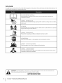
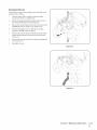
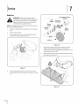
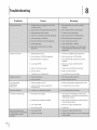
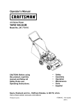
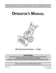
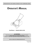
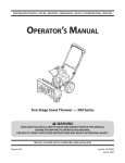
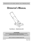
Safe Operation
Practices • Set-Up • Operation
• Maintenance
• Service • Troubleshooting
OPER roR's
• Warranty
L
Chipper/Shredder
Vacuum
Model CSV 020
MTD LLC, P.O. BOX 361131 CLEVELAND, OHiO 44136-0019
PrintedIn USA
FormNo.769-06164
(May27,2010)
1
ToTheOwner
Thank¥ou
Thank you for purchasing
a Chipper/Shredder
Vacuum
the right to change
equipment
without
manufactured
by MTD. It was carefully engineered to provide
excellent performance
when properly operated and maintained.
Please read this entire manual
It instructs
prior to operating
your machine.
persons
who will operate
If you have any problems or questions concerning the machine,
phone your local authorized MTD service dealer or contact us
the equipment.
you how to safely and easily set up, operate
maintain
and
directly.
Please be sure that you, and any other
the machine,
carefully
follow
product
in this manual
information
the
at the time of printing.
may not be applicable
to all models.
all references
are observed
website
at all times.
to fightand
from the operating
manufacturer
numbers,
on this page. We want
is responsible
left side of the
position
for all engine-related
power-rating,
specifications,
warranty and service. Please refer to the engine manufacturer's
Owner's/Operator's
Manual, packed separately with your
Manual may cover a range of product specifications
for various
models. Characteristics
and features discussed and/or illustrated
in this manual
satisfaction
this manual,
issues with regards to performance,
this manual frequently to familiarize yourself with the machine,
its features and operation.
Please be aware that this Operator's
telephone
Throughout
The engine
Review
Support
address can be found
to ensure your complete
machine
is relative to the most recent
available
MTD's Customer
address and mailing
recommended
safety practices at all times. Failure to do so could
result in personal injury or property damage.
All information
product specifications,
designs and
notice and without
incurring obligation.
machine,
for more information.
We reserve
Tableof Contents
Safe Operation
Practices ........................................
3
Service .....................................................................
14
16
Assembly & Set-Up ..................................................
Controls & Features ................................................
7
10
Troubleshooting
Opera tion ................................................................
11
Warranty
Maintenance
12
& Adjustment
.................................
Replacement
RecordProductinformation
Before setting
up and operating
information
in the provided
area to the right. You can locate the
Support
Department,
support
17
20
NNDNDNDNDND
please
and record the
model plate by standing at the operator's position and looking
down at the rear of the deck. This information
will be necessary,
should you seek technical
Parts .................................................
................................................................
MODEL NUMBER
your new equipment,
locate the model plate on the equipment
.....................................................
SERIAL NUMBER
via our web site, Customer
or with a local authorized
NDDDDDDDDDD
service dealer.
CustomerSupport
Please
do NOT return
If you have difficulty
this machine,
the machine
assembling
to the retailer
this product
you can seek help from
Visit us on the web at www.mtdproducts.com
0
Call a Customer
0
Write
Support
Representative
without
or have any questions
the experts.
0
or dealer
Choose
from
at (800) 800-7310
us at MTD LLC • RO. Box 361131 • Cleveland,
first contacting
regarding
the options
the controls,
below:
or (330) 220-4683
OH • 44136-0019
our Customer
operation,
Support
Department.
or maintenance
of
2
ImportantSafeOperationPractices
WARNING:
This symbol
could endanger
all instructions
points out important
the personal
safety and/or
in this manual
with these instructions
before
property
attempting
may result in personal
When you see this symbol
safety instructions
of yourself
to operate
which,
if not followed,
and others.
this machine.
Read and follow
Failure to comply
injury.
- NEED ITS WARNING!
CALIFORNIA
PROPOSITION
65
WARNING: Engine Exhaust, some of its constituents,
and certain vehicle components
contain or emit chemicals known to State of California to cause cancer and birth defects
or other reproductive
harm.
DANGER: This machine
this manual.
operator
was built to be operated
As with any type of power
can result in serious injury. This machine
toes and feet and throwing
result in serious injury
machine
all instructions
and in the manual(s) before
assemble
future
and follow
and operate.
and regular
on the
attempting
Keep this manual
reference
is capable
practices
in
or error on the part of the
of amputating
the following
fingers,
hands,
safety instructions
could
or death.
8.
Read, understand,
to the safe operation
carelessness
debris. Failure to observe
Training
1.
according
equipment,
opening,
to unclog
remove
either the feed intake or discharge
or empty
bag, or inspect
and repair the
machine while the engine is running. Shut the engine off
and wait until all moving parts have come to a complete
to
in a safe place for
and for ordering
Never attempt
stop. Disconnect
replacement
the spark plug wire and ground
it against
the engine.
parts.
2.
Preparation
Be familiar with all controls and their proper operation.
Know how to stop the machine and disengage them
1.
quickly.
3.
and safe operation
and on the machine
adult.
4.
5.
without
and deadly
indoors
2.
contains
carbon
chambers
the rotating
feet.
Always wear safety glasses or safety goggles
proper
and while
Wear sturdy, rough-soled
and discharge
can amputate
feeding
4.
material
fingers,
Contact
with
hands, and
which
or repair,
ricochet
can
work shoes and close-fitting
clothes or jewelry
Before starting,
in the chipper
can be
5.
Maintain
necessary.
chute.
check all bolts and screws for proper
to be sure the machine
condition. Also, visually
frequent intervals.
parts or in the
opening.
during
an adjustment
caught in movable parts. Never operate this machine
in bare feet or sandals. Wear leather work gloves when
tightness
impeller
performing
slacks and shirts. Loose fitting
area.
an odorless
and cause
to the machine.
to protect your eyes. Thrown objects
cause serious injury to the eyes.
gas.
Do not put hands and feet near rotating
or damage
operation
at least 75 feet from
Stop machine if
monoxide,
could be picked up or thrown
injury
by an
3.
or in a poorly ventilated
which
personal
enters the area.
Never run an engine
feeding
in this manual
and supervised
this machine
Keep bystanders, pets, and children
the machine while it is in operation.
Engine exhaust
7.
practices
and be trained
Never allow adults to operate
instruction.
anyone
6.
objects
Never allow children under 16 years of age to operate this
machine. Children 16 and over should read and understand
the instructions
Thoroughly
inspect the area where the equipment
is to
be used. Remove all rocks, bottles, cans, or other foreign
or replace
inspect
is in safe working
machine
safety and instructions
for any damage
labels, as
at
4.
SafeHandlingof Gasoline:
To avoid personal
in handling
injury or property
gasoline. Gasoline
vapors are explosive.
damage
is extremely
Serious personal
use extreme
flammable
1.
Use only an approved
2.
Never fill containers
gasoline
3.
inside a vehicle
remove gas-powered
possible,
then refuel such equipment
portable
nozzle.
container,
5.
from
6.
opening
at all times
Extinguish
ignition.
all cigarettes,
until fueling
is complete.
Never fuel machine
7.
Never remove
7.
cigars, pipes and other sources of
indoors.
before
bottom
10.
If gasoline is spilled, wipe it off the engine and equipment.
Move unit to another area. Wait 5 minutes before starting
8.
9.
securely.
or other debris build-up.
10.
free of grass, leaves,
11.
any fuel soaked debris.
Never store the machine
inside where
there is an open flame, spark or pilot
light as on a water
heater, space heater, furnace, clothes
dryer or other
12.
chambers
the rotating
feet.
and discharge
impeller
gas
Before starting
the machine,
feed intake, and cutting
debris.
3.
Thoroughly
chamber
J
SECTION 2 --
chute,
are empty and free of all
to be shredded
injury
with
hands, and
cans, or other foreign
which could cause personal
machine.
4
Contact
make sure the chipper
inspect all material
any metal, rocks, bottles,
fingers,
and remove
objects
or damage to the
IMPORTANT SAFE OPERATION
Personal injury
parts have stopped,
disconnect
it against the engine
the
before
debris.
Never operate
without
vacuum
bag and discharge
Never operate
without
chute
or change
bag must
operation.
either the inlet nozzle or optional
while the engine is running.
Keep all guards, deflectors
PRACTICES
and safety devices in place and
properly.
Keep your face and body back and to the side of the
chipper chute while feeding material into the machine
Never operate
kickback
this machine
without
good visibility
or light.
and keep a firm hold on the
Do not operate
level surface.
this machine
on a paved, gravel or non-
14.
Do not operate
this machine
while
alcohol
to
injuries.
13.
parts or in the
opening.
can amputate
the
result.
Always be sure of your footing
handles.
Operation
Do not put hands and feet near rotating
through
larger than
or in this manual.
could
to
proper
Never attempt to unclog either the feed intake or discharge
opening while the engine is running. Shut the engine off,
avoid accidental
or fuel container
of material
to shred or chip material
damage
material
area. This can prevent
on the machine
attachment
Clean up oil or fuel spillage and
appliances.
2.
Do not attempt
operating
To reduce fire hazards, keep machine
of processed
to assure
properly attached to the machine. Never empty
vacuum bag while the engine is running.Vacuum
the engine.
feeding
up in the discharge
parts.
hose attachment
(if applicable) properly attached to
the machine. Never attempt to attach or change either
Replace gasoline cap and tighten
1.
Do not allow an accumulation
be kept closed at all times during
of filler neck to allow space for fuel
9.
12.
Check for any loose parts and tighten
continued safe operation.
clearing
gas cap or add fuel while the engine is hot or
expansion.
remove
c.
spark plug wire and ground
Never over fill fuel tank. Fill tank to no more than 1/2
inch below
11.
Repair or replace any damaged
or machine
refueling.
8.
b.
specified
Do
device.
Allow engine to cool at least two minutes
the following
Inspect for damage.
wait until all moving
6.
running.
it against the engine and perform
discharge and result in kickback
feed opening.
on a trailer with a
with the rim of the fuel tank or
not use a nozzle lock-open
or if your machine
noise or vibration,
a.
build
If this is not
rather than from a gasoline dispenser
Keep the nozzle in contact
container
5.
on the
equipment
object
an unusual
steps:
filling.
the truck or trailer and refuel it on the ground.
4.
ground
can ignite.
or on a truck or trailer
before
strikes a foreign
start making
immediately
shut the engine off. Allow the impeller to
come to a complete stop. Disconnect the spark plug wire,
container.
away from your vehicle
When practical,
care
and the
bed with a plastic liner. Always place containers
ground
should
injury can occur when
gasoline is spilled on yourself or your clothes which
Wash your skin and change clothes immediately.
If the impeller
under the influence
of
or drugs.
15.
Muffler and engine
not touch.
16.
Never pick up or carry machine
17.
If situations
become
occur which
hot and can cause a burn. Do
while the engine is running.
are not covered
in this manual,
care and good judgement.
Contact Customer Support
assistance and the name of the nearest service dealer.
use
for
Maintenance & Storage
Never tamper
operation
2.
with safety devices. Check their proper
to keep the machine
Also, visually
if needed.
inspect
Before cleaning,
condition.
for any damage
and repair,
machine
repairing,
Disconnect
or inspecting,
5.
stop the engine
and all moving
parts have
the spark plug wire and ground
against the engine to prevent
4.
at frequent
in safe working
and make certain the impeller
stopped.
To avoid serious injury
regularly.
Check bolts and screws for proper tightness
intervals
3.
Do not modify engine
unintended
it
starting.
with factory
to operate
may include
the following
Modification
(EM), Oxidizing
SparkArrestor
safety and instruction
7.
or fuel container
there is an open flame, spark or pilot
clothes dryer, etc.
8.
Allow
to cool at least 5 minutes
9.
Always refer to the operator's manual
instructions
on off-season storage.
on regular
gasoline,
and
systems: Engine
Air
internal combustion
engine and should not be used
machine isforest-covered,
equipped with an
on ARNING:
or near anyThis
unimproved
_
brushcovered
or grass-covered
before
storing.
for proper
If the fuel tank has to be drained,
do this outdoors.
11.
Observe proper disposal laws and regulations
etc. to protect the environment.
for gas, oil,
land unless the
engine's exhaust system is equipped with a spark
attester meeting applicable local or state laws (if
inside where
10.
12.
control
Catalyst (OC), Secondary
any).
Ira spark arrester is used, it should
machine
unleaded
emission
(SAI) and Three Way Catalyst (TWC) if so equipped.
light such as a water
heater, furnace,
governor.
labels, as
Follow this manual for safe loading, unloading,
transporting,
and storage of this machine.
Never store the machine
of engine
are certified
operating
or replace
in any
Engines which are certified to comply with California and federal
EPA emission regulations for SORE (Small Off Road Equipment)
Injection
Maintain
engine
Notice Regarding Emissions
necessary.
6.
setting
Do not change the engine governor settings or overspeed
the engine. The governor controls the maximum safe
speed of the engine.
or death, do not modify
way. Tampering with the governor setting can lead to a runaway
engine and cause it to operate at unsafe speeds. Never tamper
working
order by the operator.
above is required
be maintained
by law (Section
4442 of the California
Resources Code). Other states may have similar
apply on federal lands.
A spark attester for the muffler
nearest engine authorized
department,
in effective
In the State of California
is available
laws. Federal laws
through
service dealer or contact
P.O. Box 361131 Cleveland,
the
Public
your
the service
Ohio 44136-0019.
According to the Consumer Products Safety Commission
(CPSC) and the U.S. Environmental
Protection Agency (EPA),
this product
has an Average Useful Life of seven (7) years,
or 60 hours of operation.
Life have the machine
At the end of the Average Useful
inspected
annually
by an authorized
service dealer to ensure that all mechanical and safety
systems are working properly and not worn excessively.
Failure to do so can result in accidents,
injuries
or death.
SECTION 2 --
IMPORTANT SAFE OPERATION
PRACTICES
S
Safety Symbols
This page depicts and describes safety symbols that may appear
machine before attempting
to assemble and operate.
on this product.
Read, understand,
and follow
all instructions
on the
READ THE OPERATOR'S MANUAL(S)
Read, understand,
assemble
and follow
all instructions
in the manual(s) before
WARNING--
to
ROTATING BLADES
Keep hands out of inlet and discharge openings
blades inside
o
attempting
and operate
while
machine
is running.
There are rotating
®
BYSTANDERS
Keep bystanders,
Stop machine
WARNING--
pets, and children
if anyone
at least 75 feet from the machine
while
it is in operation.
enters the area.
THROWN OBJECTS
This machine
may pick up and throw and objects which
can ricochet.
EYE PROTECTION
Always wear safety glasses or safety goggles
WARNING--
WARNING--
follow
and instructions
before refueling.
or in a poorly ventilated
area. Engine exhaust contains carbon
an odorless and deadly gas.
Your Responsibility--Restrict
the warnings
the use of this power machine
in this manual
to persons
and on the machine.
SAVETHESEINSTRUCTIONS!
6
I
SECTION 2 --
IMPORTANT SAFE OPERATION
this machine.
CARBON MONOXIDE
Never run an engine indoors
WARNING:
operating
GASOLINE IS FLAMMABLE
Allow the engine to cool at least two minutes
monoxide,
when
PRACTICES
who read, understand
and
3
Assembly
& Set-Up
Contentsof Carton
One Chipper/Shredder
Vacuum
One Operator's
Manual
One Safety Glasses
of Oil
Assembly
NOTE:This
One Engine Operator's
One Bac
One Upper and Lower Handle
One Bottle
Manual
2.
Unfold the upper
handle until it aligns with lower
handle.
Make sure the rope guide is on the right side of upper
unit is shipped
without
gasoline
or oil in the engine.
Fill up gasoline and oil as instructed in the accompanying
engine
manual BEFORE operating your chipper shredder vacuum.
handle.
See Fig. 3-2A.
f
Handle
1.
Remove the hairpin
clips from
the handle
brackets and the
carriage screws and wing nuts from the lower handle.
a.
Place the bottom
holes in lower handle over the
pins on the handle brackets
pointing downwards
See Fig. 3-1.
with notch in handle
and secure with hairpin
clips.
/
Figure 3=2
3.
Secure the two handles bytightening
bolts must be seated properly
3-2B.
/
/
/
/
Figure 34
b.
Insert carriage
screws through
upper
hole in lower
handle from the inside and secure with wing
See Fig. 3-1.
nuts.
the star knobs (carriage
into the handle). See Fig.
4_
Loosen the wing nut that secures the rope guide to the
right side of upper
handle.
a.
Slowly pull starter
b.
Slip the starter
c.
Tighten
Bag
1.
rope out of engine.
Grasp bag handle with one hand and slide locking
rod on
mounting
Use
bracket
with other hand toward
the end of mounting bracket
locking rod. See Fig. 3-4.
rope into the rope guide.
the wing nut. See Fig. 3-3.
engine.
as leverage when
sliding
the
Figure 3-4
Figure
3-3
2_
Slip bag over the rim of the discharge
locking
opening
and release
rod to secure bag in place.
3.
Snap bag clip to the top of the lower handle.
4.
Place the lower straps on the bag over the top of lower
handle,
hooking
NOTE:The
them
bag/chute
on the studs. See Fig. 3-4.
switch button
attached
to the
mounting
bracket must be fully depressed by the tip of
front tab on bag handle when securing the bag or engine
will not start.
8
I
SECTION3 --
ASSEMBLY&
SET-UP
Adjustments
Set-Up
NozzleHeight
GasandOil Fill-Up
The nozzle can be adjusted
5/8" to 4 1/8" ground
adjusted
1.
according
to any six positions,
ranging
clearance. The nozzle height
to chipper
shredder
Depress nozzle height adjustment
See Fig. 3-5.
from
has to be
conditions.
lever towards
Refer to the separate engine owner's
manual
for additional
engine information.
1.
Add oil provided
of the box.
2.
Service the engine with gasoline as instructed
wheel.
before
starting
unit for the first time out
in the
Engine manual.
_
gasoline. Gasoline is extremely flammable
and the
vapors are explosive.
WARNING:
Use extreme
Nevercare
fuel when
the machine
handling
indoors
or while
Extinguish
the engine
cigarettes,
is hot or running.
cigars, pipes and other
sources of ignition.
_
running or until the engine has been allowed to cool
WARNING:
fill fuel
indoors with engine
for
at least twoNever
minutes
aftertank
running.
Figure 3-5
2.
Move the height adjustment
lever forward or backward to
adjust the nozzle upwards or downwards.
Make sure both
levers are in the same position.
3.
Release lever towards
NOTE: In general,
deck. See Fig. 3-5.
raise the nozzle height to vacuum
thick layer of leaves. Lower the nozzle height
surfaces.
a
for smoother
SECTION3 --
ASSEMBLY
& SET-UP
9
4
Controls
and Features
Bag
Recoil
Chip|
Nozzle Height
Adjustment
Lever
J
Figure 44
WARNING:
The operation
can result in foreign
objects
of any chipper shredder
being thrown
eyes, which can damage your eyes severely. Always
wear the safety glasses provided with this unit or
eye shields while
adjustments
operating
or while
performing
any
or repairs.
Yard waste such as leaves or pine needles
through the nozzle for shredding.
shredded
vacuumed
Allows twigs and small branches
for chipping.
up to 1-1/2" in diameter
See Fig. 4-1.
the nozzle ground
approximately
5/8" to 4 1/8".
clearance
up
fed through
the chipper
chute or
the nozzle.
RecoilStarter
behind
ranging
material
through
The recoil starter
Nozzle Height AdjustmentLever
Used to adjust
to be
can be vacuumed
Bag
Collects
Chipper Chute
fed into the impeller
Nozzle
into the
is attached
to the right upper
handle.
Stand
unit and pull the recoil starter to start engine.
EngineControls
See the separate
the controls
engine manual
on the engine.
for the location
and function
of
Operation
Starting & Stopping Engine
5_
Twist the two buttons
empty
Refer to the Engine Operator's manual packed with your chipper/
shredder vacuum for instructions
on starting and stopping the
engine.
contents.
while emptying
on the back of the bag to unlock and
See Fig. 5-2. Hold bag handle and bag clip
the contents.
F
1"oEmptyBag
1.
Unhook
bag straps from the lower handle.
2.
Unsnap bag clip from the top of lower handle.
See Fig. 5-1.
J
Figure 5-2
6.
Compress
7.
Fold outer flap over inner flap and insert buttons
bag through
8.
Figure 5-1
3_
4.
instructed
bracket
with other hand toward
engine to
and fold inner flap over opening.
metal outlets.
Twist the buttons
Grasp bag handle with one hand and pull lock rod on
mounting
release.
bag opening
on the
See Fig. 5-2.
to lock bag. Place bag back onto unit as
in Assembly
& Set-Up.
adjustments
_
without first stopping engine and
ARNING: Dospark
not at
anywire.
time make any
disconnecting
plug
Lift bag off back of unit.
vacuum any material larger than specified on the
WARNING:
attempt Personal
to shred,
chip, oror
machine or inDo
thisnotmanual.
injury
damage to the machine
could
result.
IMPORTANT:The
flail screen is located inside the housing in
the discharge area. If the flail screen becomes clogged, remove
and clean as instructed
performance,
in Maintenance
it is also important
& Adjustments.
to keep the chipper
For best
blade
sharp.
11
6
Maintenance& Adjustments
Maintenance
Equipment Care
Clean the chipper/shredder
use.
General Recommendations
Always observe
maintenance.
The warranty
safety rules when
performing
on this chipper/shredder
any
vacuum
Wash bag periodically
in shade.
does not
must maintain
the equipment
as instructed
NOTE:Cleaning
here.
recommended
Changing
of engine-governed
should
be checked at least once each
shredder
check all fasteners
WARNING:
Always stop engine,
plug, and ground
against
disconnect
engine before
any type of maintenance
spark
performing
on your machine.
Lubrication
1.
Lubricate each wheel shoulder screw (rear wheel) and pivot
arm axle (front wheel) once a season with light oil.
2.
Lubricate the pivot points of the nozzle height adjustment
levers once a season with light oil. See Fig. 6-1.
Figure 6-1
4.
spray of water is not
the fuel system.
the locking
rod with
of attaching
vacuum
for all engine
Manual
packed with your chipper/
maintenance.
and make sure these are
il_llii_li
application
remove and clean as
as it could contaminate
Refer to the Engine Operator's
tight.
Lubricate
with a forceful
to dry thoroughly
Engine Care
All adjustments
season.
3.
clogged,
after each
speed will void engine
wa rra nty.
Periodically
thoroughly
with water. Allow
If the flail screen becomes
instructed
below.
cover items that have been subjected to operator abuse or
negligence. To receive full value from warranty, operator
vacuum
light oil to ease the
on or removing
Follow the separate engine manual
for lubrication
instructions.
bag.
packed with your unit
maintenance
on the machine, wait for all parts to
WARNING:
Before
performingthe any
typeplugof wire.
stop moving and
disconnect
spark
Failure to follow this instruction could result in
personal
injury or property
damage.
F
Removing the FlailScreen
If the discharge area becomes
and clean area as follows:
clogged,
remove the flail screen
1.
Stop the engine. Make certain the chipper/shredder
vacuum has come to a complete stop.
2.
Before unclogging
ground
the discharge
chute, disconnect
the spark plug wire to retaining
3.
Remove the vacuum bag from the unit as instructed
OPERATION section to obtain access to flail screen.
4.
Remove self tapping
attaches
5.
in the
screw on right side of unit that
to the flail screen. See Fig. 6-2.
Remove hex screw on top of rear housing
bracket
and
post.
near mounting
and the flange lock nut that secures flail screen.
See Fig. 6-2.
6.
Remove and clean the screen by scraping
water. See Fig. 6-3.
7.
Reinstall
or washing
with
the screen.
Figure 6-2
\
Figure 6=3
SECTION 6 --
MAINTENANCE
& ADJUSTMENTS
13
7
Service
F
BladeCare
Front Support Bracel
L6ck N ut
maintenance
on the machine, wait for all parts to
ARNING:
performingthe any
typeplugof wire.
stop
moving Before
and disconnect
spark
Failure to follow this instruction could result in
_kk
personal
NOTE: When tipping
keep engine
1.
injury or property
Bell
Washer
damage.
Thrust
Washer
the unit, empty the oil and fuel tank and
spark plug side up.
Disconnect
and ground
Pivot Arm
Assembly
/
Shoulder
Screw
the spark plug wire to retaining
post.
2.
Remove bag assembly.
3.
Remove the three hex cap screws holding
chute to the upper
housing.
the chipper
See Fig. 7-1.
Lock Nut
Figure 7-2
5.
Remove the shoulder
screws, thrust
washers that go through
support brace. The front support
removed at this time as well.
6.
washers, and bell
the pivot arms to the front
brace and lock nut can be
Remove the three screws on the upper
housing
that secure
the nozzle cover. See Fig. 7-3.
F
Figure 7-1
4.
Remove the flange lock nuts, front wheels,
and wave
washers that attach to the pivot arm assemblies.
7-2.
See Fig.
\
J
Figure 7-3
Carefully
tilt and support
underneath
the unit up to provide
to the nozzle mounting
hardware
access
10.
and impeller.
The nuts on the flat head cap screws can be reached
from underneath
Remove the three shoulder bolts securing the black plastic
lower flail housing to the lower housing. Refer to Fig. 7-4.
extension.
using a 1/2-inch
socket, universal,
and
See Fig. 7-6.
,_
/ ..................
,
/
Impeller
Nuts
,J
Figure
7-6
Figure 7-4
11.
8_
Tilt top of black plastic
engine to remove.
lower flail housing
9.
Using a 3/16" allen wrench,
screws that hold the chipper
remove
toward
the
Replace or sharpen
sharpened
the flat head cap
blade to the impeller.
These
screws are accessible through the opening created when
the chipper chute was removed earlier. See Fig. 7-5.
blade. The blade can be
wheel.
sharpening blade, wear leather work gloves to
ARNING:
blade the
is sharp.
protect
your The
handschipper
and follow
originalWhen
angle of
_
grind.
12.
Reassemble
opposite
by performing
order and manner
NOTE:Tighten
Flat Head
Ca
chipper
with a file or on a grinding
steps in the
of removal.
blade screws to 210 - 250 in-lbs. Make
certain chipper
facing
the previous
blade is reassembled
with the sharp edge
upward.
Off-SeasonStorage
When storing
unventilated
to rustproof
the chipper/shredder
or metal storage
the non-painted
or silicone, coat the equipment,
bearings,
in an
be taken
surfaces. Using a light oil
especially
any springs,
and cables.
Remove all dirt from exterior
Chipper
Blade
vacuum
shed, care should
Follow lubrication
Refer to engine
instructions.
Store equipment
of engine and equipment.
recommendations.
manual
for correct engine storage
in a clean, dry area. Do not store in an
area where equipment
is present that may use a pilot light
or has a component
that can create a spark.
Figure 7-5
SECTION
7 -- SERVICE
15
Troubleshooting
Problem
Engine runs erratic
Cause
!
Remedy
1. Spark plug boot loose.
1. Connect and tighten
2. Unit running
2. Move choke lever to OFF position.
on CHOKE (if equipped).
3. Blocked fuel line or stale fuel.
spark plug boot.
3. Clean fuel line; fill tank with clean, fresh
gasoline.
4. Lowengine
RPM.
4. Always run engine at full throttle
(if
equipped).
Occasional skips
(hesitates) at
5. Water or dirt in fuel system.
5. Drain fuel tank. Refill with fresh fuel.
6. Dirty air cleaner.
6. Referto
7. Carburetor
7. See authorized
out of adjustment.
engine manual.
service dealer.
1. Spark plug gap too close.
1. Remove spark plug and adjust gap to .030".
high speed
2. Carburetor
improperly
2. See authorized
Unit does not discharge
1. Discharge area clogged.
idle mixture
set.
adjustment
service dealer.
Stop engine immediately
and disconnect
spark plug wire. Clean flail screen and inside
of discharge
2. Foreign object
3. Lowengine
4. Vacuum
lodged in impeller.
RPM.
bag is full.
opening.
2_
Stop engine and disconnect spark plug wire.
Remove lodged object.
3_
Always run engine at full throttle.
4. Empty bag.
9
Replacement
Parts
Component
1
Part Number
and Description
664-04040
Bag
981-0490
Chipper Blade
719-0329
Flail Blade (2 total)
734-1987
Wheel
17
19
MANUFACTURER'S
LiMiTED WARRANTY
The limited warranty set forth below is given by MTD LLC with
respect to new merchandise purchased and used in the United States
and/or its territories and possessions, and by MTD Products Limited
with respect to new merchandise purchased and used in Canadaand/
or its territories and possessions (either entity respectively, "MTD").
"MTD" warrants this product (excluding its Normal Wear Parts and
Attachments as described below) against defects in material and
workmanship for a period of two (2) years commencing on the date
of original purchase and will, at its option, repair or replace, free of
charge, any part found to be defective in materials or workmanship.
This limited warranty shall only apply if this product has been
operated and maintained in accordance with the Operator's Manual
furnished with the product, and has not been subject to misuse,
abuse, commercial use, neglect, accident, improper maintenance,
alteration, vandalism, theft, fire, water, or damage because of other
peril or natural disaster. Damage resulting from the installation or use
of any part, accessory or attachment not approved by MTD for use
with the product(s) covered by this manual will void your warranty as
to any resulting damage.
Normal Wear Parts are warranted to be free from defects in material
and workmanship for a period of thirty (30) days from the date of
purchase. Normal wear parts include, but are not limited to items
such as: batteries, belts, blades, blade adapters, tines, grass bags,
wheels, rider deck wheels, seats, snow thrower skid shoes, friction
wheels, shave plates, auger spiral rubber, engine oil, air filters, spark
plugs and tires.
Attachments-- MTD warrants attachments for this product against
defects in material and workmanship for a period of one (1) year,
commencing on the date of the attachment's original purchase or
lease. Attachments include, but are not limited to items such as:
grass collectors and mulch kits.
HOWTO OBTAINPARTSAND SERVICE:Warranty service is available,
WITH PROOFOF PURCHASE,through your local authorized service
dealer. To locate the dealer in your area:
In the U.S.A.
Check your Yellow Pages, or contact MTD LLC at RO. Box 361131,
Cleveland, Ohio 44136-0019, or call 1-800-800-7310, 1-330-2204683 or log on to our Web site at www.mtdproducts.com.
In Canada
Contact MTD Products Limited, Kitchener, ON N2G4J1, or call 1-800668-1238 or log on to our Web site at www.mtdcanada.com.
This limited warranty does not provide coverage in the following
cases:
a.
FOR
c. Service completed by someone other than an authorized service
dealer.
d. MTD does not extend any warranty for products sold or exported
outside of the United States and/or Canada, and their respective
possessions and territories, except those sold through MTD's
authorized channels of export distribution.
e. Replacement parts that are not genuine MTD parts.
f. Transportation charges and service calls.
g. MTD does not warrant this product for commercial use.
No implied warranty, including any implied warranty of
merchantability or fitness for a particular purpose, applies after
the applicable period of express written warranty above as to the
parts as identified. No other express warranty, whether written or
oral, except as mentioned above, given by any person or entity,
including a dealer or retailer, with respect to any product, shall
bind MTD. Duringthe period of the warranty, the exclusive remedy
is repair or replacement of the product as set forth above.
The provisions as set forth in this warranty provide the sole and
exclusive remedy arising from the sale. MTD shall not be liable
for incidental or consequential loss or damage including, without
limitation, expenses incurred for substitute or replacement lawn
care services or for rental expenses to temporarily replace a
warranted product.
Some states do not allow the exclusion or limitation of incidental
or consequential damages, or limitations on how long an implied
warranty lasts, so the above exclusions or limitations may not apply
to you.
In no event shall recovery of any kind be greater than the amount of
the purchase price of the product sold. Alteration of safety features of
the product shall void this warranty. You assume the risk and liability
for loss, damage, or injury to you and your property and/or to others
and their property arising out of the misuse or inability to use the
product.
This limited warranty shall not extend to anyone other than the
original purchaser or to the person for whom it was purchased as a
gift.
HOWSTATELAW RELATESTO THIS WARRANTY: This limited
warranty gives you specific legal rights, and you may also have other
rights which vary from state to state.
IMPORTANT: Owner must present Original Proof of Purchase to
obtain warranty coverage.
Log splitter pumps, valves, and cylinders havea separate oneyear warranty.
b. Routine maintenance items such as lubricants, filters, blade
sharpening, tune-ups, brake adjustments, clutch adjustments,
deck adjustments, and normal deterioration of the exterior finish
due to use or exposure.
MTD LLC, P.O. BOX 361131 CLEVELAND, OHIO 44136-0019; Phone: 1=800=800=7310, 1=330=220-4683
MTD Canada Limited - KITCHENER, ON N2G 4J1; Phone 1-800-668-1238
GDOC-100016 REV. C