1
ISIS® Software for
PHOENIX XT and MENTOR
User Manual
Software v. 1.54
Lighting Technologies
M 1253
1106.01.253
Chapter Overview
1
2
3
4
5
6
7
8
9
10
11
12
13
14
15
16
17
18
19
20
21
22
23
24
25
26
27
28
29
30
31.
32
INTRODUCTION..................................................................................................................................... 2
WORKING FIELDS................................................................................................................................. 5
PHYSICAL AND VIRTUAL FADERS..................................................................................................... 7
QUICK START GUIDE ......................................................................................................................... 25
CHANNEL CONTROL .......................................................................................................................... 29
SUBMASTERS ..................................................................................................................................... 47
GROUPS............................................................................................................................................... 96
BANKS ................................................................................................................................................ 113
LIVE ..................................................................................................................................................... 130
RECORDING AND LOADING MEMORIES .................................................................................. 139
RECORDING AND MODIFYING TIMES....................................................................................... 196
SEQUENCE MANAGER AND EVENTS........................................................................................ 228
PLAYBACKS AND PLAYBACK CONFIGURATION ..................................................................... 254
CHASERS ....................................................................................................................................... 291
EFFECTS ........................................................................................................................................ 327
MACROS......................................................................................................................................... 358
COPY AND PART FUNCTIONS .................................................................................................... 372
PATCH............................................................................................................................................. 389
SPECIAL CHANNEL NUMBERING............................................................................................... 432
HTP – FTP – LTP MODES............................................................................................................. 441
COLOUR CHANGERS ................................................................................................................... 459
MOTION CONTROL SETUP.......................................................................................................... 533
MOTION CONTROL USE .............................................................................................................. 584
MOTION CONTROL LIBRARIES................................................................................................... 641
MIDI Control .................................................................................................................................... 651
Networking....................................................................................................................................... 652
SHOW MANAGEMENT.................................................................................................................. 656
HELP ............................................................................................................................................... 683
USING THE ALPHANUMERIC KEYBOARD ................................................................................ 685
PHOENIX 10 SYSTEM................................................................................................................... 688
ADDITIONAL SOURCES OF INFORMATION .............................................................................. 697
CHAPTER OVERVIEW .................................................................................................................. 698
www.adblighting.com
Page:1
Issue 1.01
Introduction
1 INTRODUCTION
1.1
Welcome to the ISIS User Manual
ISIS software from ADB is an advanced approach to the control of lighting systems. It provides the
operator total command over standard luminaires, colour changers and moving light instruments.
ISIS is an evolutionary software platform, designed with the most advanced development techniques
and characterised by a perfectly structured architecture. The software design allows ISIS to be open
to further expansion and innovation for many years to come.
One of the concepts behind ISIS is to make the system intuitive for the operator, whether control is
required over a small generic lighting system, or a rig comprising many moving lights and DMX
instruments. Many functions have been incorporated into ISIS following suggestions from lighting
professionals from around the World.
Any show programmed on ISIS can be run on any other console or PC running ISIS software. This
means that shows can be easily transported between different lighting desks, and the operator can be
quickly familiarised with other consoles of the ISIS family.
ISIS software is running on a powerful real-time 32-bit operating system, providing multi-user and
pre-emptive multi-tasking capabilities, with a very short boot-up time. This system has proved highly
reliable and stable.
1.1.1 About this manual
This manual describes the functions of ISIS software in detail, and provides examples of their use.
The information in some chapters is partially included in other sections, to guide the operator through
a complete procedure.
The manual is split into logical chapters, allowing the required information to be found quickly. It is
designed to be useful for those operators who prefer to use the manual when necessary, as well as for
those who would like to follow the chapters from start to finish.
In addition to this manual, the ISIS software contains a complete on-line help system, accessed by
pressing the <HELP> key. The on-line help system contains hypertext links between various topics,
allowing relevant information to be quickly found. Importantly, using the on-line help does not affect
the physical operation of the lighting desk: all faders and controls can still be used whilst the on-line
help is active. Use of the on-line help system is described in the chapter *HELP*.
All functions and operations performed from the control platform can be made from the alphanumeric
keyboard supplied with the system. The chapter *USING THE ALPHANUMERIC KEYBOARD*
explains how the desk and fader selections can be made in this way. The alphanumeric keyboard is
also used to input titles and other information when required. ISIS recognises commands made from
both the control platform and the alphanumeric keyboard simultaneously without the operator having
to enable one or the other.
The chapter *QUICK START GUIDE* provides a very simplified guide to the most common
requirements and functions of the lighting desk: it can be used as a quick reference chart or as a basic
tutorial to the ISIS system.
Page:2
Issue 1.01
www.adblighting.com
Introduction
1.1.2 Main features of the ISIS software
ISIS provides all the operating functions expected of a high performance lighting control system, and
in particular:
2
3
4
5
6
7
8
9
10
11
12
13
14
15
16
17
18
Intuitive control of channels and memories in submasters, playbacks or Live;
Powerful and flexible submasters with configurable functions for each submaster;
Completely user-configurable screen displays show the information required;
All channels and parameters within a memory can run different fade times simultaneously;
Advanced sequence manager allows any event to be inserted into the playback sequence and
triggered by the operator;
Easy modifications can be made from the channel and memory tracking functions;
Complete control over chasers and pre-programmed effects;
Unrestricted allocation of luminaires, colour changers and moving lights to control channels and
DMX outputs: a 20 parameter instrument requires 20 DMX outputs, but only one control channel;
Each channel and parameter can be set to one of three operating modes: HTP, FTP or LTP;
Extended motion control functions include move in black, tracking functions, and more;
Sophisticated concept of libraries for motion control elements;
Smart patch for DMX inputs and outputs, including proportional output factors and dimmer laws;
Selective multi-merge of show data;
MIDI control;
Standard comprehensive Ethernet functions include full tracking back-up and DMX through
Ethernet;
Standard Ethernet functions can be expanded to include extensive Ethernet systems;
Comprehensive on-line help system with hypertext links.
ISIS is Integrated Software for Intelligent Systems!
1.2
Introduction to Using the ISIS System
Before using an ISIS system for the first time, the basic methods used to navigate the system and
select functions should be understood.
1.2.1 Access to functions
Access to ISIS functions is provided through the menu bar, accessed by pressing the <MENU> key,
although there are also dedicated keys for many functions.
The most commonly required functions are loaded onto the eight function keys F1 to F8, which are
displayed at the bottom of the screen. The functions assigned to these keys will change as the
operator performs different functions, providing immediate access to the most logical functions.
1.2.2 Navigation
The <MENU> key displays the main menu bar, from which functions can be selected. The menu bar
can be navigated using the function keys to make the selection indicated by the numbers 1 to 8, or the
arrow (or cursor) keys used to highlight a function which is then selected with the <ENTER> key.
Many menu selections will bring up a display, or dialogue box, on screen, where the operator can
browse and configure options and make selections. Again, these dialogue boxes can be navigated
using the four arrow keys and the <ENTER> key, or the function keys F1 to F8 directly.
Items can be highlighted from lists using the arrow keys, but more directly by using the main fader
wheel. Pressing <ALT> in combination with an arrow key will produce the functions <HOME>, <END>,
<PAGE UP> and <PAGE DOWN> when navigating longer lists.
www.adblighting.com
Page:3
Issue 1.01
Introduction
Numerical items in any manager or list can be directly selected by typing the number on the keypad.
The number entered will appear in the information bar at the bottom of the list, and can be reset one
digit at a time by pressing <CLEAR>.
Each dialogue box is given a number within its title - for example, 810: Screen Configuration. If a
dialogue box is regularly used, its number can be used to display the dialogue box directly, instead of
accessing the function through the menu.
The shortcut to displaying the required dialogue box is to hold down the <MENU> key and type the
associated dialogue number on the keypad.
1.2.3 Messages
From time to time, ISIS displays messages to the operator on the screen. These appear in a small
blue window which automatically disappears after approximately five seconds, or on a subsequent
keypress. The latest message is at the bottom of this message list.
If the operator wishes to redisplay the blue message window, this facility is available from the Tool
functions of the menu, under the option ‘Show Messages’.
1.3
Summary
ADB’s ISIS software provides the operator with complete command over the lighting control system.
The software is very easy to use and, once the basics have been mastered, the system is highly
intuitive.
It is not necessary to understand all of the concepts and functions of the ISIS system before it can be
used: the lighting for many shows can be controlled straight away using only the submaster faders.
However, the advanced functions of ISIS give the operator control of stage lighting to a precise and
repeatable level. The software offers highly sophisticated controls and can be customised as required
by the operator.
We hope that you will enjoy using the ISIS software and, with the aid of this manual, learning to
exploit this high performance system.
Page:4
Issue 1.01
www.adblighting.com
Working Fields
2 WORKING FIELDS
2.1
Introduction
ALL PHOENIX and VISION 10 consoles use a system of working fields.
Some other desks use a system of “editors” where work is carried out, and then sent (or assigned)
either automatically or manually to the required part of the desk; such as a submaster.
PHOENIX and VISION 10 (and also other ADB desks such as TENOR) require the desired working
field to be selected first: all work carried out on the keypads is automatically sent to the selected field.
To select a field, simply press its white selector key.
The LED in the key lights up when the field is selected.
For example, select submaster 15 by pressing the <15> key above the fader.
All subsequent operations of the channels and memories keypad, special functions panel, and motion
controller will be sent to submaster 15; until a different field is selected.
Working fields are easily identified by their white selector keys:
Submasters 1 to 48
(17 to 48 or 25 to 48 by turning submaster pages)
P1 Preset 1
S1 Stage 1
P2 Preset 2
(Not Phoenix2)
S2 Stage 2
(Not Phoenix2)
LIVE Live
EDMEM Edit Memory
Whichever field is selected, it “receives” the commands made on other parts of the control surface.
If channels are allocated intensities when a submaster is selected, the submaster now contains those
channels with their intensities.
All the basic functions such as channel selection, intensity allocation, recording and loading memories
(or cues), colour and motion control can be carried out in all of the working fields, but some of the
different fields have other functions associated to them.
For example, submasters can be used for special effects, Live for capturing channels, and the
playbacks (Stage and Preset fields) for complex memory sequences.
Any memory created in any field can be loaded into any other field for playback or modification
purposes, and field contents or memories can be copied from one area or list to another.
So, simply select the desired working field before commencing other commands. Selecting either S1
or S2 will make subsequent channel manipulations visible at the output of the desk, and appear on
stage.
The Live field is, as its name implies, also concerned with the output of the desk; but in this instance
any channels modified will be captured, so that further manipulations of those channels in other fields
will not alter the live output of the desk.
If a submaster is selected, the fader must be raised to see its contents on stage (and these channels
will be shown in the live field), although keeping the fader down is a useful way of creating scenes
“blind”.
Using the Preset side of a playback, rather than the Stage/Studio side, is also an easy way of plotting
blind, particularly if the newly created blind state is to be played back as the next operation.
To empty the contents of a working field, press <erase> twice while it is selected.
www.adblighting.com
Page:5
Issue 1.01
Working Fields
2.2
To Select a Working Field
To select any of the working fields, simply press its associated white selector key: its LED will light.
To select more than one submaster, use the white selector keys in conjunction with the <+>, <->, and
<THRU> keys.
Playback fields and special function fields (such as edit memory, live and the patch) are exclusive:
they cannot form part of a list of selected fields.
Page:6
Issue 1.01
www.adblighting.com
Physical and Virtual Faders
3 PHYSICAL AND VIRTUAL FADERS
3.1
Introduction
Because ISIS software is able to run on a variety of hardware platforms, the software may support
faders, keys, or other controls that do not physically exist.
When this happens, the controller is known as a virtual controller.
The most obvious example of this is the submasters.
The software supports 48 submasters but there are physically only 24 faders (16 on PHOENIX 2).
If submaster page 1 is selected, submasters 25 to 48 (17 to 48 on PHOENIX 2) are virtual.
®
In the case of the submasters, the page can be turned to give physical access to these higher
numbered submasters, but there are other faders within the software that are always virtual.
Sometimes, due to operational manipulations, there is a discrepancy between the level of a physical
fader and its associated virtual fader. In this case, it is the virtual fader that is contributing to the desk
output status and to regain manual control of it, the physical fader must be moved to the same level as
the virtual fader.
When the levels match, the physical fader takes control. This is called “collecting” the fader. In all
screen displays, virtual fader levels are displayed in red, whereas physical fader levels are shown in
white. When the physical fader is moved, the level display will turn from red to white when the physical
fader matches the virtual fader level.
At this point, the operator has control of the fader level. Virtual fader levels can also be entered directly
as keyboard commands, or in conjunction with the fader wheel.
Functions that do not have a physical fader or key at all are controlled by a simple code of keystrokes
from the alphanumeric keyboard or by assigning them to the wheel.
In fact, all functions can be controlled in this way and a full list of all the keyboard shortcuts is given in
the section *USING THE ALPHANUMERIC KEYBOARD*.
3.2
Fader Sampling at Power up
Except for the grand master and playback faders, it is the values of the virtual faders rather than the
physical faders that are restored on power-up of the desk.
If submasters were left at specific values when the desk was shut down, those values are restored on
power-up, even if the faders have been moved in the meantime.
The grand master is an exception to that rule, so that if the desk is turned off but channels have been
left at the output, the grandmaster can be faded down while the desk is off to avoid those channels
coming straight back on at the next power-up.
It is the physical level of the grandmaster that is loaded at power-up, not the virtual.
3.3
The GRAND MASTER Fader and BLACKOUT Functions
All the hardware platforms, except for VISION 10 RB and PHOENIX RB, have both a grand master
fader and a blackout key.
www.adblighting.com
Page:7
Issue 1.01
Physical and Virtual Faders
The alphanumeric keyboard is used to access functions when no physical controls are present, or
should the operator prefer to do so.
examples of keystrokes
</> <B><O>
Activates the blackout function: this toggles the blackout function on and off. When
blackout is activated there is no output from the desk, the LED in the B/O key flashes, and “B-O”
in red is displayed in the GM box on monitor 1.
<=> <G><M> <PGUP>
Increases the level of the grand master.
<=> <G><M> <PGDN>
Decreases the level of the grand master.
3.4
The Override Fader
The override fader is controlled by a pair of keys, <OVE+> and <OVE->, on all hardware platforms
except PHOENIX 2, VISION 10 RB and PHOENIX RB, in which case it is entirely virtual. The override
facility forces intensities beyond 100% of their current level, up to 140%, but works on all channels
proportionally. Intensities that are at FF cannot go beyond 100%, but intensities that are less than
100% can be proportionally increased until they reach 140% of their original level or absolute 100%,
whichever comes first. This is the opposite function of the grand master fader: where the grand master
proportionally decreases intensities, the over-ride fader proportionally increases them. <OVE-> is used
to return the level back to 100%, but not lower.
examples of keystrokes
<=> <o><v> <pgup>
Proportionally increases the output of all channels until they reach 140% of their initial
value.
<=> <o><v> <pgdn>
Proportionally decreases the output of all channels until they return to their initial value.
OR
<F6 (WHEEL)> <F8 (OTHER)> <F2 (OVER)> <Wheel / Belt>
<F6 (WHEEL)> <F8 (OTHER)> <F2 (OVER)> <pgup>
<F6 (WHEEL)> <F8 (OTHER)> <F2 (OVER)> <pgDN>
3.5
The Auditorium Fader
The auditorium is a special group, or list of channels, which is allocated to the auditorium fader.
This group can then be manually faded down or out at any time, as the fader has an inhibitive effect.
One example of using this feature would be to allocate all the front of house lights in a traditional
proscenium theatre to the auditorium fader.
Then, whenever the house curtain is lowered, all lights that would otherwise spill onto it can be faded
out as and when required.
3.5.1 Allocating channels to the auditorium fader
The channel list assigned to the auditorium fader can be added to or changed at any time.
Page:8
Issue 1.01
www.adblighting.com
Physical and Virtual Faders
examples of keystrokes
<MENU> <F7 (SETUP)> <F5 {auditorium}>
Displays a simple channel list.
Auditorium channel selection (Dialogue Box 840)
...
<enter> <enter> etc.
Selects the first channel and moves the cursor down to the next channel in the list. Each
time, press <ENTER> to confirm.
...
<> <> etc.
The arrow keys can be used to highlight a non-consecutive channel from the list, which is
then selected with <ENTER>.
<f8 {ok}>
Confirms the selection and exits the dialogue box, returning to the working field previously
selected.
OR
<MENU> <F7 (SETUP)> <F5 {auditorium}>
Displays a simple channel list.
www.adblighting.com
Page:9
Issue 1.01
Physical and Virtual Faders
<> <> <> <enter> etc.
Selects the first channel required in a list.
<F2 {thru}> <><><> <F2 {thru}>
Selects the through function, then the last channel required in a list, and finally turns off the
through function.
<F8 {ok}>
Confirms the list selection and exits the dialogue box, returning to the working field
previously selected.
OR
examples of keystrokes
<MENU> <F7 (SETUP)> <F5 {auditorium}>
Displays a simple channel list.
<> <> <> <enter>
By using the arrow keys and the <enter> key,
<><> <enter>
individual channels can be selected,
<> <> <> <enter>
as required, from the list. Using this method, channels are only included in the auditorium
list when the <enter> key is pressed.
<F8 {ok}>
Confirms the list selection and exits the dialogue box, returning to the working field
previously selected.
Page:10
Issue 1.01
www.adblighting.com
Physical and Virtual Faders
3.5.2 Using the auditorium fader
The auditorium fader is used to manually inhibit the channels allocated to it when required.
It can be useful to manually fade out the front-of-house lights when the tabs are flown in - hence the
name of the function.
However, the auditorium fader can also be used for any group of channels that need manual control in
this way, such as working lights or music stands.
VISION 10 has a dedicated auditorium fader, whilst PHOENIX 10 has an auxiliary fader that can be
assigned the auditorium group. On all other systems, the auditorium fader is a virtual control. In this
case, the auditorium level can be assigned to the wheel, or adjusted via the alphanumeric keyboard.
examples of keystrokes
<=> <a><u> <Pgdn>
On the alphanumeric keyboard, fades down the channels allocated to the auditorium
group.
<=> <a><u> <PgUP>
On the alphanumeric keyboard, raises the auditorium level once it has been decreased.
Note : The auditorium fader is purely inhibitive.
It can fade down the channels allocated to it if they are present at the output from other working fields.
It cannot add those channels to the output unless they are present elsewhere.
For more information on inhibit, please turn to the *SUBMASTERS AND BANKS* section.
3.5.3 Assigning the wheel (belt) to the auditorium fader
For easier adjustment of the auditorium fader level, it can be temporarily assigned to the wheel.
examples of keystrokes
<f6 {wheel}> <F4 {auditm}>
Assigns the wheel (or belt) to the auditorium fader
WHEEL (OR Belt) up
Adjusts the level of the auditorium fader
www.adblighting.com
Page:11
Issue 1.01
Physical and Virtual Faders
<f6 {wheel}> <F1 {intens}>
Re-assigns the wheel to intensities.
While the wheel is assigned to the auditorium fader, the wheel box in the information bar on monitor 1
changes from “Wh Intens” to “Wh Auditm” to indicate the special function of the wheel (or belt).
3.6
The Submasters
There are 48 submasters on all platforms, but only 24 physical faders (16 faders on PHOENIX 2 ).
Each of these faders can have a non-zero value at any time, but only one page of submasters can
have physical control.
The levels of individual submasters are displayed on screen in the submaster information boxes.
Because of the concept of submaster pages, it is likely that there will be discrepancies between the
positions of the actual submaster faders and their virtual values.
This is indicated by the submaster level being shown on the monitors in white if it is the physical value
controlling the submaster level, or in red if it is the virtual value controlling the submaster level.
When there is a difference such as this, manual control of the submaster can be taken by moving the
physical fader so that its level matches that of the virtual fader.
When the match is made, the submaster value on the screens changes from red to white to show that
the physical fader is in control of the submaster level.
Any submaster can be controlled by the physical fader by changing pages as required.
If a page change is not desirable, the virtual faders of the unselected submaster page(s) can be
controlled from the alphanumeric keyboard.
examples of keystrokes
<=> <0><1> <PGUP>
Fades up submaster 1.
<=> <0><2> <PGDN>
Fades down submaster 2.
<=> <%>
Returns control to channel intensities.
Note: These functions alter the submaster fader values without actually selecting the submaster. If Stage 1 is
selected, it will remain selected while the submaster virtual faders are modified.
When submasters on the first page are set to non-zero values and the submaster page is turned, the
position of the physical faders is different from the position of the virtual faders.
Page:12
Issue 1.01
www.adblighting.com
Physical and Virtual Faders
There is a function in the submaster configuration dialogue box that sets the virtual fader value to the
physical fader of the selected submaster(s) on the selected page.
For example: if submaster 1 is set to 50% and the page turned so that the physical fader becomes
submaster 25 (submaster 17 on PHOENIX 2 ), the fader is at 50% but the virtual value of submaster
25 (17) is still zero.
Either the operator moves the physical fader down to zero to match the virtual value (shown in red in
the submaster information box), or the “faders” function can be used to force the virtual value to match
the physical position of the selected submaster.
examples of keystrokes
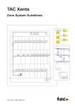
<sub 1> <CONFIG>
Enters the submaster configuration dialogue box (for submaster 1 only).
<F2 {FADERS}>
Forces the virtual value of submaster 1 to match the position of the fader.
<F8 {OK}>
Confirms the action.
Submaster Configuration Dialog Box
3.7
The Submaster General Fader
The submasters can be individually assigned to the submaster general fader.
This is a master fader that has overall control of the levels of all submasters that are allocated to it.
www.adblighting.com
Page:13
Issue 1.01
Physical and Virtual Faders
It is entirely virtual on all operating surfaces (except VISION10, where the function can be assigned to
the auxiliary fader). The submaster general fader has optional usage: individual submasters do not
have to be assigned to it.
For example, submasters 1 to 12 could be allocated to the submaster general fader while submasters
13 to 24 remain independent of it.
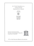
The submaster general fader and flash master faders are configured in the submaster configuration
dialogue box, along with submaster and flashkey modes.
examples of keystrokes
<sub. selection> <config>
Displays the submaster configuration dialogue box for submaster 1.
Submaster General Fader Configuration Dialog Box
examples of keystrokes
<>
Pressing the down arrow key 6 times moves the cursor to the submaster general fader
box.
<enter>
Selects or deselects the option, thus allocating the selected submaster(s) to the submaster
general fader.
Page:14
Issue 1.01
www.adblighting.com
Physical and Virtual Faders
<f8 {ok}>
Confirms the selection and exits the dialogue box.
Once the submaster(s) have been allocated to the submaster general, the fader must have its virtual
level set by using the alphanumeric keyboard or the wheel.
examples of keystrokes
<=> <s><m> <pgup>
Increases the level of the submaster general fader.
<=> <s><m> <pgdn>
Decreases the level of the submaster general fader.
3.7.1 Assigning the wheel (belt) to the submaster general fader
For easier adjustment of the submaster general fader level, it can be temporarily assigned to the fader
wheel.
examples of keystrokes
<f6 {wheel}> <F2 {submst}>
Assigns the wheel (or belt) to control the submaster general fader.
WHEEL (OR Belt) up
Adjusts the level of the submaster general fader.
<f6 {wheel}> <F1 {intens}>
Re-assigns the wheel to intensities.
While the wheel is assigned to the submaster general fader, the wheel box in the information bar on
monitor 1 changes from “Wh Intens” to “Wh SubMst” to indicate the special function of the wheel (or
belt).
3.8
The Flash Master
In a similar fashion to the submaster General fader, each submaster flashkey can be allocated as
required to a flash general fader.
Where, normally, the contents of a submaster are flashed to full, they will be flashed to an intensity
relative to the level of the flash general master.
The submaster flashkeys are allocated to the flash general fader in the same submaster configuration
dialogue box as shown above.
www.adblighting.com
Page:15
Issue 1.01
Physical and Virtual Faders
examples of keystrokes
<submaster selection> <config>
Displays the submaster configuration dialogue box for submaster 1.
…
<>
Pressing the down arrow key 7 times moves the cursor to the submaster general fader
box.
<enter>
Selects or deselects the option, thus allocating the selected submaster(s) to the flash
general fader.
<f8 {ok}>
Confirms the selection and exits the dialogue box.
Once the submaster(s) have been allocated to the flash general fader, the fader must have its virtual
level set by using the alphanumeric keyboard or the wheel.
examples of keystrokes
<=> <f><l> <pgup>
Increases the level of the flash general fader.
<=> <f><l> <pgdn>
Decreases the level of the flash general fader.
3.8.1 Assigning the wheel (belt) to the flash master fader
For easier adjustment of the flash master fader level, it can be temporarily assigned to the fader
wheel.
Page:16
Issue 1.01
www.adblighting.com
Physical and Virtual Faders
examples of keystrokes
<f6 {wheel}> <F3 {flash}>
Assigns the wheel (or belt) to control the flash master fader.
wheel (Or belt) up
Adjusts the level of the flash master fader.
<f6 {wheel}> <F1 {intens}>
Re-assigns the wheel to intensities.
While the wheel is assigned to the flash master fader, the wheel box in the information bar on monitor
1 changes from “Wh Intens” to “Wh Flash” to indicate the special function of the wheel (or belt).
3.9
The DMX input fader
When an external desk is connected to a PHOENIX or VISION 10 via the DMX input, the input patch
is subject to the level of the DMX input fader.
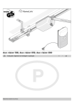
This fader is also entirely virtual and its value is set and enabled from the general configuration
dialogue box in the setup menu.
Assigning the DMX In Fader from the General Configuration Dialog Box (Dialogue box 866)
examples of keystrokes
<menu> <f7 {setup}> <f3 {general}>
Displays the General Configuration dialogue box, giving access to all input options.
www.adblighting.com
Page:17
Issue 1.01
Physical and Virtual Faders
<enter>
Enable the DMX input by checking the box.
<> WHEEL (OR belt)
Moves the cursor to the DMX input level, if required. The DMX input level can be set
proportionally: 0% is the minimum, 100% is the maximum. A value of 50% will produce an output
of half the DMX input levels. The fader wheel (or belt) can be used to set the input level, or it may
be entered directly from the keypad.
<f8 {ok}>
Page:18
Issue 1.01
Confirms the operation and closes the dialogue box.
www.adblighting.com
Physical and Virtual Faders
3.9.1 Assigning the wheel (belt) to the DMX input fader
For easier adjustment of the DMX input fader level, it can be temporarily assigned to the fader wheel.
examples of keystrokes
<f6 {wheel}> <F5 {DMX in}>
Assigns the wheel (or belt) to control the DMX input fader.
WHEEL (OR BELT) DOWN
Adjusts the level of the DMX input fader.
<f6 {wheel}> <F1 {intens}>
Re-assigns the wheel to intensities.
While the wheel is assigned to the DMX input fader, the wheel box in the information bar on monitor 1
changes from “Wh Intens” to “Wh Dmx In” to indicate the special function of the wheel (or belt).
3.10 The Audio Input fader
To enable the audio functions, a suitable input level must be set with the audio input fader.
If an audio signal is connected, its level can be visualised on-screen via bargraphs to help optimise the
setting of the audio input.
The audio input fader is entirely virtual and is controlled within the same general configuration
dialogue box as shown above.
examples of keystrokes
<menu> <f7 {setup}> <f3 {general}>
Displays the General Configuration dialogue box.
<><> <enter>
Enables the audio input by checking the box.
www.adblighting.com
Page:19
Issue 1.01
Physical and Virtual Faders
<> wheel (or belt) down
Move the cursor to the audio input level, if required. The audio input level can be set
between 0% and 100% (the input is unattenuated). The fader wheel (or belt) can be used to set
the input level, or it may be entered directly from the keypad.
If the audio input is connected and active, average, bass, mid-range, and treble bargraphs
are displayed on-screen to give a visualisation of the audio input level. The optimum level should
allow the signal to peak occasionally, but not persistently. The required level will vary between
different input sources.
Assigning the Audio Input from the General Configuration dialog box (Dialogue box 866)
<f8 {ok}>
Confirms the operation and closes the dialogue box.
3.10.1 Assigning the wheel (belt) to the audio input fader
For easier adjustment of the audio input fader level, it can be temporarily assigned to the fader wheel.
examples of keystrokes
<f6 {wheel}> <F6 {audio}>
Assigns the wheel to control the audio input fader.
wheel (or Belt) down
Adjusts the level of the audio input fader.
Page:20
Issue 1.01
www.adblighting.com
Physical and Virtual Faders
<f6 {wheel}> <F1 {intens}>
Re-assigns the wheel to intensities.
While the wheel is assigned to the audio input fader, the wheel box in the information bar on monitor 1
changes from “Wh intens” to “Wh Audio” to indicate the special function of the wheel (or belt).
3.11 Using the Fader Wheel (Belt) to Control the Virtual Faders
As described above, all the virtual faders can be temporarily assigned to the fader wheel or belt
instead of setting their levels from the alphanumeric keyboard. However, when the wheel (or belt) is
assigned to a virtual fader function, it cannot be used for adjusting intensities. The fader assignment is
shown in the information bar on monitor 1 above the screen footer.
By default this is shown as “Wh Intens” for intensities, but the selected virtual fader is shown in this
box when it is assigned to the wheel.
Re-assigning the wheel (or belt) to control any of the virtual faders is achieved via the function keys.
examples of keystrokes
<f6 {wheel}> <F2 {submst}>
Assigns the wheel to control the submaster general fader.
wheel (Or BELT) UP/DOWN
Adjusts the level of the Submaster General Fader.
examples of keystrokes
<f6 {wheel}> <F3 {flash}>
Assigns the wheel to control the flash master fader.
wheel (Or BELT) UP/DOWN
Adjusts the level of the flash master fader.
<f6 {wheel}> <F4 {auditm}>
Assigns the wheel to control the auditorium fader.
www.adblighting.com
Page:21
Issue 1.01
Physical and Virtual Faders
wheel (Or BELT) UP/DOWN
Adjusts the level of the auditorium fader.
<f6 {wheel}> <F5 {DMX in}>
Assigns the wheel to control the DMX input fader.
wheel (Or BELT) UP/DOWN
Adjusts the level of the DMX input fader.
The value of the DMX input will be changed in this way, although there is no direct display
of the level on-screen. The level can be checked via the General Configuration Dialog Box as
shown above.
<f6 {wheel}> <F6 {audio}>
Assigns the wheel to control the audio input fader.
Note that the actual value of the audio input will be been changed in this way, although
there is no direct display on-screen. The level can be checked via the General Configuration
dialog box as shown above.
wheel (Or BELT) UP/DOWN
Adjusts the level of the audio input fader
<F6 {wheel}> <F7 {PARAM}>
Assigns to the wheel control of motion control parameters.
<f6 {wheel}> <F8 {other}>
Provides access to other virtual faders that can be assigned to the wheel, such as effect
speed <F1 {SpdEff}> and override <F2 {Over}>.
Page:22
Issue 1.01
www.adblighting.com
Physical and Virtual Faders
<f6 {wheel}> <F1 {intens}>
Assigns the fader wheel (or belt) back to control intensities. This should be done after
using the wheel to control any of the virtual faders.
3.12 Summary
Any virtual fader can be controlled via the alphanumeric keyboard, using the <PAGE UP> and <PAGE
DOWN> keys. The required fader must first be assigned by using the <=> (equals) key, followed by
the fader’s abbreviation. These are shown below.
Fader Abr.
=GM
=OV
=AU
=AX
=SM
=FL
= 0 1 to 4 8
=S1
=P1
=S2
=P2
=XX
= YY
Value
pgup / pgdn
pgup / pgdn
pgup / pgdn
pgup / pgdn
pgup / pgdn
pgup / pgdn
pgup / pgdn
pgup / pgdn
pgup / pgdn
pgup / pgdn
pgup / pgdn
pgup / pgdn
pgup / pgdn
Result
Sets the value of the Grand Master fader.
Sets the value of the Over-ride fader.
Sets the value of the Auditorium fader.
Sets the value of the Auxiliary fader.
Sets the value of the Submaster general fader.
Sets the value of the Flash general fader.
Sets the value of the individual submaster fader.
Sets the value of the Stage 1 fader.
Sets the value of the Preset 1 fader.
Sets the value of the Stage 2 fader.
Sets the value of the Preset 2 fader.
Sets the value of the trackball (PAN only).
Sets the value of the trackball (TILT only).
Example: ‘= G M’ for control of the grand master
3.13 Warning (end of chapter)
If the desk is to be turned off, it is important to shut down the software properly before turning
off the power.
A correct shutdown ensures that all the files in the working directory “data \ work” are properly updated
and saved, and that important system files are not corrupted. This procedure ensures that the show is
restored on the next power-up.
examples of keystrokes
<menu>
Enters the menu.
<f1 {file}>
Selects the file menu.
<f8 {shutdown}>
www.adblighting.com
Page:23
Issue 1.01
Physical and Virtual Faders
Selects the shutdown procedure.
A warning is issued.
A warning is given: This will stop all Phoenix / ISIS services
Are you sure?
<F7 {YES}>
Confirms the shutdown.
All the files in the “data \ work” directory are properly updated, saved, and closed.
The system can be safely switched off when the monitor displays the message “Power Down”.
Page:24
Issue 1.01
www.adblighting.com
Quick Start Guide
4 QUICK START GUIDE
4.1
Turning ON
Turning on the power is known as a warm start. After a normal warm start, the desk is
exactly as it was left - submasters loaded, fades running, all memories etc intact.
Power switches are located on the front of the external processing unit and the rear of
Phoenix systems. For Vision, there is a single power switch on the left hand side of the
front edge, beneath the trim.
The monitor displays the system’s warm start routine: you can see all the ISIS files,
and the current show, being loaded.
Warning:
Selecting and initialising the
Configuration option will reset
the monitor displays to their
default settings.
Show Initialisation (clearing the desk)
It may be desirable to initialise the system – clearing previous work from the desk. To
initialize the desk, allow the system to boot normally and then select <Show Init> in the
File option of the Menu. This allows areas of the desk to be selected for deletion.
Confirm with <F8 (OK)>.
…
Working Field Selection
All channel operations are sent to the selected Working Field: press the white selector
key associated with the desired field prior to entering channels and intensities. The
content of the Working Field is displayed on the monitor.
4.2
…
…
Channel Selection
On systems with one keypad (Phoenix 2 & Phoenix 5), any entered number is assumed
to be a channel number unless told otherwise. Therefore, simply type the desired
channel number on the keypad.
On systems with two keypads (Phoenix 10 & Vision 10), enter the desired channel
number on the dedicated Channels keypad.
4.3
Intensity Assignment
After a channel has been entered, the <AT> key is pressed to assign an intensity level.
ISIS is a Single Digit Direct Entry system, so intensities can be entered as follows:
50% would be entered as <5>
25% as <2><.><5>
100% (or Full On) is <AT><AT>
0% is 0.
.
or
The <AT> key is not required for use of the <WHEEL>, <FF>, <00>, <+5%> or <-5%>
keys, although it does not matter if <AT> is accidentally pressed prior to these keys.
www.adblighting.com
or
Page:25
Issue 1.01
Quick Start Guide
4.4
Memory Number Selection
On single keypad systems (Phoenix 2 & Phoenix 5), precede the memory number with
the <MEM> key.
On dual keypad systems (Phoenix 10 & Vision 10), enter the memory number on the
dedicated Memories keypad.
4.5
Recording Memories
To record the contents of the selected Working Field only, enter the memory number
and use <REC>.
To record the total desk output, excluding any bypassed channels, use <SUM>.
4.6
Assigning Memories Times
When recording any memory, the default time will be associated to the memory.
To specify memory Up and Down times, press the <UP> or <DOWN> key, enter the
time (in seconds), then press <UP> or <DOWN> for a second time.
If both times are to be changed to the same value, the keystrokes can be shortened by
pressing the <UP> key, entering the time (in seconds), followed by the <DOWN> key.
4.7
Loading Memories
Select the desired Working Field, then select the desired memory number and press
<LOAD>.
Loading will replace the contents of the selected Working Field with the memory
selected.
4.8
Sequential Memory Playback
Each playback has two sides: S for Stage, which is output to the dimmers, and P for
Preset, which is effectively blind. The stage and preset halves of the playbacks are
analogous with a two preset manual desk. In order to playback pre-recorded memories
in sequential order, the <SEQ> button must be illuminated.
Playbacks can be operated manually by moving the S and P fader pairs, or
automatically by pressing the <GO> key. A running crossfade can be paused and unpaused by using the <HOLD> key.
4.9
Erasing Contents
Erase removes the contents of a Working Field. Press <ERASE> twice. But if it is a
recorded entity such as a memory or chaser, it is not deleted from the system memory.
Page:26
Issue 1.01
www.adblighting.com
or
Quick Start Guide
4.10 Deleting
All deleting (permanent removal) is done from the relevant manager. For example:
to delete a memory, use memories manager;
to delete a group, use group manager.
…
4.11 Creating Chasers
Select a submaster, press <CHASER>, select the required chaser number, and press
<LOAD>.
Press <ADD> to create each new step, and then enter the channels, groups, or
memories required and assign an intensity level. Chasers are started and stopped
using the Flashkey associated with the submaster containing the chase, whilst the
overall intensity level is set with the fader.
4.12 Creating Effects
Select a submaster, press <EFFECT>, select the required effect number, and press
<LOAD>. Enter the channels, groups, or memory contents required in the effect in the
order desired.
The effect type can be changed by selecting <TYPE> and selecting from the list of
effects.
Effects are started and stopped using the Flashkey associated with the submaster
containing the effect.
4.13 Output Patch
To change the output patch, press <PATCH> to enter the Patch Screen. The syntax for
patching is:
channel number to dimmer number at proportional level
Press <PATCH> a second time or <F8> when complete.
www.adblighting.com
Page:27
Issue 1.01
Quick Start Guide
4.14 Saving a Show
The current show can be saved to disk. Use the Menu as shown, or the dedicated
<TO DISK> key, enter a filename and description using the alphanumeric keyboard, and press <F8
(OK)> to complete the operation. The save progress is shown on the monitor.
…
4.15 Shut Down
If the desk is to be turned off, it is important to shut down the software properly before turning off the
power. A correct shutdown ensures that all the files in the working directory are properly updated and
saved so that the show is restored on the next power-up.
Page:28
Issue 1.01
www.adblighting.com
Channel Control
5 CHANNEL CONTROL
5.1
Introduction
This chapter describes how to make channel selections and allocate intensities to individual or lists of
channels.
The channel keypad works directly in the selected working field.
If submaster 1 is selected, the channels will be sent to submaster 1.
If Stage 1 is selected, the channels will be sent there and so on.
To see the output from a submaster, its fader must be raised to send its contents to the output.
Please also check that the Grand Master is raised to 100%, and the Blackout is not activated - the
LED in the blackout key should be off, and the top line of the display on monitor 1 should show “GM
FF”.
The channel keypad and associated functions work in the following fields:
Submasters 1 to 48
Playback 1 (S & P)
Playback 2 (S & P)
Live
Edit Mem
It is also used for auditorium configuration, patch, print operations and during the programming of
other functions.
5.2
Selecting Channels
When channels are selected, they are shown highlighted with a white background on monitor 1.
If a list of channels is selected, they are all shown with a white highlight on monitor 1, and the last
entered channel number is displayed in the information line towards the bottom of monitor 1.
After an intensity is given, the next number entered is assumed to be a new channel number, so the
previous channel selection is cancelled automatically.
Pressing the <CLEAR> key once clears the last number entered from the selection; pressing
<CLEAR> twice clears all selections made from the channel and memory keypads.
examples of keystrokes
<1>
Selects channel 1.
www.adblighting.com
Page:29
Issue 1.01
Channel Control
<1> <+> <2>
Selects channels 1 and 2.
<1> <+> <2> <+> <1><7>
Selects channels 1 and 2 and 17.
<1> <THRU> <3><0>
Selects the list of channels 1 to 30.
<1> <THRU> <3><0> <+> <4><5>
Selects the list of channels 1 to 30, and channel 45.
<1> <THRU> <3><0> <-> <2><8> <+> <4><5>
Selects the list of channels 1 to 30, except 28, and plus channel 45.
<ALL>
Selects all the channels that currently have an intensity (non-zero or “visible” channels).
<1> <THRU> <1><0><0> <-> <ALL>
Selects all channels with no intensity in the selected range. (In this example the range is 1
to 100).
<ALL> <-> <4><1> <THRU > <4><5>
Selects all the non-zero channels, except those in the selected range. (In this example the
range is 41 to 45).
<1><2><0> <+> <NEXT> <+> <NEXT>
Selects channels 120 and 121 and 122.
Page:30
Issue 1.01
www.adblighting.com
Channel Control
<2><5><0> <+> <PREV> <+> <PREV>
Selects channels 250, 249 and 248.
<1><0> <thru-on> <8><0> <thru-on> or <ENTER>
Selects all non-zero intensity channels between 10 and 80.
<1><0><1> <thru-on> <thru-on>
Selects all non-zero intensity channels from 101 onwards.
<invert>
Swaps the current channel selection for all other non-zero intensity channels.
<solo>
Keeps selected channels at their respective intensities, and temporarily removes all other
channels in the selected field from the output. The solo function is cancelled by pressing <clear>
or <solo> for a second time.
<CLEAR>
Clears the last entered number from a selection.
<CLEAR> <CLEAR>
Clears the current channel and memory selection.
<last>
Re-selects the last channel selection made before the keypad was cleared.
<erase> <erase>
Removes all channels from the selected field.
www.adblighting.com
Page:31
Issue 1.01
Channel Control
5.3
Allocating Intensities
When a channel selection is made, it must be given an intensity value by entering digits on the
keypad, or by using the wheel (digital fader endless belt on PHOENIX 2).
examples of keystrokes
<1> <AT> <7>
Sets channel 1 to 70%.
<1> <AT> <7><.><3>
Sets channel 1 to 73%.
<1> <AT> <6><+5%>
Sets channel 1 to 65% (VISION 10 & Phoenix 10 only).
<1> <AT> <6><-5%>
Sets channel 1 to 55% (VISION 10 & Phoenix 10 only).
<1> <AT> <.><5>
Sets channel 1 to 5%.
Page:32
Issue 1.01
www.adblighting.com
Channel Control
<1> WHEEL (or BELT)
Sets channel 1 to any level between 0% and 100% (FF).
<1> <FF>
Sets channel 1 to FF (100%) (VISION 10 only).
<1> <AT> <AT>
Sets channel 1 to FF (100%).
<1> <00>
Sets channel 1 to 00 (zero) (VISION 10 & PHOENIX 10 only).
<1> <AT> <0>
Sets channel 1 to 00 (zero) (single keypad systems).
<RET>
Returns the currently selected channel(s) to its / their previously unmodified intensity
level(s). Return cannot work after the selection has been cleared with <clear> <clear>.
This method of intensity allocation is known as “Single digit direct entry” because tens of percent are
entered as a single digit i.e. 50% is entered as just “5”. ISIS can emulate “Two digit direct entry”
systems (i.e. 50% entered as 5 0, or 47% entered as 4 7 rather than 4.7) by holding down the <AT>
key whilst entering the intensity.
®
examples of keystrokes
www.adblighting.com
Page:33
Issue 1.01
Channel Control
<8> <at> <4> <7>
Sets channel 8 to 47%, if the <AT> key is held down whilst the <4> and <7> keys are
pressed.
The channel selection methods and intensity allocation methods work in tandem, so any combination
of channels can be set to any intensity levels by any of the methods shown above. Thus ISIS offers
the operator much faster, simpler and flexible means of channel control.
Some examples are given below.
®
5.3.1 Channel selection and intensity allocation
A whole list of non-sequential channel numbers can be selected in order to allocate the same intensity
to all of them.
examples of keystrokes
<1> <THRU > <6><5> <-> <2><8> <THRU > <3><2>
<+> <8><1> <THRU > <1><0><0>
<-> <8><8> <+> <1><0><0><2>
<+> <NEXT> <+> <4><7><6> <+>
Page:34
Issue 1.01
www.adblighting.com
Channel Control
<PREV> <AT> <4><.><7>
Sets channels 1 to 27, 33 to 65, 81 to 87, 89 to 100, 475, 476, 1002 and 1003 at 47%.
5.4
Advanced Intensity Modifications
Channels with intensities can be modified proportionally to their current levels, either individually or as
a list.
Using these methods, a lighting state, or part thereof, can be proportionally modified without using the
grandmaster or over-ride functions; this means that channels being output from other submasters are
not affected.
Proportional modifications are made with the wheel or by adding or subtracting any percentage to the
current levels by using the keypad.
examples of keystrokes
<1> <THRU > <1><0> WHEEL (or BELT)
Proportionally increases the intensities of channels 1 to 10. If they are at different levels,
they will increase in intensity as the wheel is moved upwards. Eventually all the channels will
reach 100%, but if the wheel is then moved downwards, they will regain their original balance and
be decreased proportionally. Similarly, if the wheel is moved downwards, all the channels will
reach an intensity of zero, but when the wheel is moved back up, they regain their original
balance.
<2><5> <thru> <2><8> <enter> <.> <5>
Channels 25 to 28 have 5% added to their original intensities. Do not use the <AT> key.
<1> <THRU > <1><0> <+><.><3>
Channels 1 to 10 have 3% added to their original intensities. Do not use the <AT> key.
www.adblighting.com
Page:35
Issue 1.01
Channel Control
<1> <THRU > <5> <at> <+> <3>
The levels of channels 1 to 5 increase proportionally by 30% of their current intensities.
<1> <THRU > <5> <at> <-> <7>
The levels of channels 1 to 5 decrease proportionally by 70% of their current intensities.
<4><1> <THRU > <4><5> <at> <+> <0><5>
The levels of channels 41 to 45 increase proportionally by 5% of their current intensities
when the <AT> key is held down.
<4><1> <THRU > <4><5> <at> <+> <5><0>
The levels of channels 41 to 45 increase proportionally by 50% of their current intensities
when the <AT> key is held down.
<4><1> <THRU > <4><5> <at> <-> <0><5>
The levels of channels 41 to 45 decrease proportionally by 5% of their current intensities
when the <AT> key is held down.
<4><1> <THRU > <4><5> <at> <-> <5><0>
The levels of channels 41 to 45 decrease proportionally by 50% of their current intensities
when the <AT> key is held down.
Page:36
Issue 1.01
www.adblighting.com
Channel Control
5.5
Allocating Intensities to Pre-recorded Groups
Once a group has been recorded, its intensity can be manipulated in the same way as a channel, or
list of channels. For information on creating groups, please see the next chapter: *GROUPS*.
examples of keystrokes
<grOUp><1> <AT> <7>
Sets group 1 to 70%
<grOUp><2> <AT> <7><.><3>
Sets group 2 to 73%
<grOUp><3> <AT> <6><+5%>
Sets group 3 to 65% (VISION 10 & Phoenix 10 only)
<grOUp><4> <AT> <6><-5%>
Sets group 4 to 55% (VISION 10 & Phoenix 10 only)
<grOUp><5> <AT> <.><5>
Sets group 5 to 5%
www.adblighting.com
Page:37
Issue 1.01
Channel Control
<grOUp><6> WHEEL (or belt)
Sets group 6 to any level between 1% and 100% (FF)
<grOUp> <7> <thru> <10> <at> <4>
Sets groups 7, 8, 9, and 10 to 40%
<grOUp><1> <+> <grOUp><5> <+><.><6>
Adds 6% to the current levels of groups 1 and 5.
The <group> key must be used before entering any group number, except during a <thru> command.
If <thru> is used, the system automatically takes the second number to mean the same type of entity
(channel, group, memory, chaser, etc.) as the first number. When creating a group list with the <+>
and <-> keys, the <group> key must be used in each case: the system always understands a number
to be a channel number unless it is prefixed with another instruction (such as <GROUP> or <MEM>).
5.6
Allocating Intensities to Pre-recorded Memories
Memories are usually played back as their recorded states, but they can also be used proportionally
as building blocks to create other states.
The channels contained in an existing memory can be selected and all given the same intensity, or the
memory itself can be given an intensity, thus keeping the proportional balance of the channels within
the memory but at an overall lower level.
examples of keystrokes
<mem> <1> <AT> <7>
The contents of memory 1 are set at 70% of their recorded intensities. Any channel at FF
in the memory will be at 70%, any channel at 70% in the memory will be at 49% and any channel
at 40% in the memory will be at 28%. The balance of the memory remains proportional.
Page:38
Issue 1.01
www.adblighting.com
Channel Control
<mem> <2> <All> <aT> <6>
All the channels that are in memory 2 are given an intensity of 60%, regardless of their
recorded levels within the memory. The balance of the memory is ignored as 60% is a finite value.
Note: PHOENIX10 and VISION 10 systems have a dedicated memories keypad: this is used directly when
selecting memories, instead of pressing the <MEM> button.
Full details on memories are given in the section *RECORDING AND LOADING MEMORIES*.
If a channel happens to be a moving light instrument or have a colour changer attached, its
parameters can be controlled whenever it is selected on the channel keypad.
This is covered in the chapters *COLOUR CHANGERS*, *MOTION CONTROL USE* and *MOTION
CONTROL SETUP*.
5.7
Copying Channels and their Intensities between the Fields
Once channels have been set in a working field (such as a submaster or playback), they can easily be
copied or moved to a different working field. This can be a very useful function.
examples of keystrokes
<sub1> <copy> <sub2> <copy>
Copies the contents of submaster 1 into submaster 2.
Note that the original contents of submaster 2 will be replaced by this operation.
<erase> <erase>
Removes the contents of submaster 1.
This has moved the contents of submaster 1 to submaster 2.
<sub1> <copy> <sub2> <thru> <sub6> <copy>
Copies the contents of submaster 1 into submasters 2 to 6.
www.adblighting.com
Page:39
Issue 1.01
Channel Control
Copy can be used in many ways for many functions. It is described fully in the section *COPY AND
PART FUNCTIONS*.
Note: The key pictures above show the COPY and PARTCOPY functions on the same key. These functions are
on separate keys on the PHOENIX 10 and VISION 10 platforms.
5.8
The Next Step...
All of these channel and intensity manipulations are required for further operations of ADB lighting
desks with ISIS software. Once the channels have been set, the next logical step is to record them as
memories.
®
The same type of manipulations are also used for creating chasers, effects, macros and for using
moving lights. The channel selection methods <+>, <->, <THRU>, <NEXT> & <PREVIOUS> are also
used in other functions such as the patch.
It is therefore very important to be familiar with the channel tools, as this will optimise the operator’s
speed on the rest of the desk. Familiarity with the layout of the keypads will help to increase plotting
speeds.
5.9
Channel Utilities
It can be useful to gain an overview of how channels are used at any time. This can be of assistance if
extra lights need to be rigged but channels or dimmers are in short supply.
The channel utilities can search for free or used channels, or track a particular channel’s usage. The
channel tracking function provides details of all memories, groups, effects, etc. in which a particular
channel is used.
For example: a channel may have been used in a group but was never recorded into any memories.
5.10 Free Channels
The free channels function is simply a list showing all the channels that have not been used in groups,
memories, chasers, effects, loops, macros, or submasters. It gives a quick overview of spare channels
that could be put to a new use.
examples of keystrokes
<menu> <f3 {channels}>
Selects the channels menu.
<f3 {info}>
Selects channel information.
Page:40
Issue 1.01
www.adblighting.com
Channel Control
<f1 {free}>
Displays the list of free (unused) channels that are patched.
5.11 Used Channels
The used channels function is simply a list showing all the channels that have already been used in
memories, chasers or effects. It gives a quick overview of channel usage and can therefore help the
operator in the management of the lighting rig.
examples of keystrokes
<menu> <f3 {channels}>
Selects the channels menu.
<f3 {info}>
Selects channel information.
<f2 {used}>
Displays the list of used channels.
5.12 Testing Channels
The test channels function is provided to assist in lamp identification or fault finding. All used channels,
or all channels in a range are sequentially flashed to a default intensity of 70% for one second, or
manually for as long as is required. During testing, the channels are sent directly to the output, after
the grandmaster. The default intensity and the duration of the flash can be changed.
www.adblighting.com
Page:41
Issue 1.01
Channel Control
examples of keystrokes
<test>
By pressing the button, directly enters the channel testing facility.
Note: This key is not available on Phoenix 2: the function must be accessed via the Channels options of the
menu.
<MENU> <F3 (CHANNEL)> <F4 (TEST)
<F1 {start}>
Starts the automatic testing of all channels. They are individually and sequentially flashed
to 70% for 1 second. These default settings can be changed by the operator.
<f2 {stop}>
Stops the test routine.
<F3 {prev}>
Selects and tests the previous channel to the one where the sequential testing was
stopped.
<f4 {next}>
Selects and tests the next channel. Using the Next and Previous functions in this way
allows channels to be tested manually instead of to a sequential pattern. Using Next and Previous
makes the selected channel appear at the output.
Page:42
Issue 1.01
www.adblighting.com
Channel Control
<f8 {EXIT}>
Stops the testing and exits the test facility.
<test>
Enters the channel testing facility.
...
<> <> <> …
Use the arrow keys to move the cursor to the first desired channel for testing.
<TAB>
On the alpha-numeric keyboard, use the <TAB> key to move the cursor to the Delay box.
Enter the time of the delay for sequential testing. The default is 1 second; the delay can be set
between 1 second and 10 seconds.
OR
<tab>
On the desk, the arrow key moves the cursor to the Intensity box. Enter the new testing
intensity from the keypad or wheel.
5.13 Channel Tracking
Channel tracking gives an overview of an individual channel’s usage. It lists all the groups, memories,
chasers and effects where that the channel is used, and its intensity within each memory. It differs
from the used channels list because it includes channels used in groups, and channel’s intensities in
memories. It is therefore a useful way of finding stray channels at unusual intensities.
For example: a zero value channel that has been controlled proportionally and therefore recorded at
less than 10% within a memory can be found.
examples of keystrokes
<select channel>
Selects the channel to be tracked.
www.adblighting.com
Page:43
Issue 1.01
Channel Control
<chtrack>
Displays the usage of the selected channel (VISION 10 & Phoenix 10 only).
OR
<select channel>
Selects the channel to be tracked.
<menu> <f3 {channels}>
Selects the channels menu.
<f3 {info}>
Selects the information menu.
<f3 {channel tracking}>
Displays the usage of the selected channel.
5.14 Summary
For ISIS® software, channel selection and intensity assignment is by SINGLE DIGIT DIRECT ENTRY.
Examples:
<1> <AT> <5>
is channel 1 at 50%.
<2> <AT> <7> <.> <5>
is channel 2 at 75%.
<3> <AT> <4> <.> <3>
is channel 3 at 43%.
<4> <FF> or <4> <AT> <AT>
is channel 4 at 100% or full (FF).
<5> <00> or <5> <AT> <0>
Page:44
Issue 1.01
www.adblighting.com
Channel Control
is channel 5 at zero (0%).
<6> <WHEEL>
is channel 6 at any intensity. The <AT> key is not required before using the wheel.
<chanNEL selection> <.> <5>
adds 5% to the current channel intensities.
<chanNEL selection> <at> <+> <5>
proportionally adds 50% of the current channel intensities.
Channel intensity allocation can be made to emulate two digit direct entry by holding down the
<AT> key:
<1> <at> <4> <7>
is channel 1 at 47%.
<chanNEL selection> <at> <+> <0> <5>
proportionally adds 5% of the current channel intensities.
<chanNEL selection> <at> <+> <5> <0>
proportionally adds 50% of the current channel intensities.
Lists of channels are made by using <+>, <->, and <THRU> keys:
<RET>
Returns the selected channel(s) to their previously unmodified level(s).
<NXT>
Selects the next numerically sequential channel number (current channel number plus 1).
<PRV>
Selects the previous numerically sequential channel number (current channel number
minus 1).
<CLEAR>
Clears the last entered number from a selection.
<CLEAR> <CLEAR>
Clears the current selection of channels.
<LAST>
Re-selects the last used channel selection.
<ERASE> <ERASE>
Erases the contents of the currently selected working field.
<GROUP>
Means the next number entered will be a group number.
<MEM>
Means that the next number entered will be a memory number.
www.adblighting.com
Page:45
Issue 1.01
Channel Control
5.15 Warning (end of chapter)
If the desk is to be turned off, it is important to shut down the software properly before turning off the
power.
A correct shutdown ensures that all the files in the working directory “data \ work” are properly updated
and saved, and that important system files are not corrupted. This procedure ensures that the show is
restored on the next power-up.
examples of keystrokes
<menu>
Enters the menu.
<f1 {file}>
Selects the file menu.
<f8 {shutdown}>
Selects the shutdown procedure.
A warning is issued.
A warning is given: This will stop all Phoenix / ISIS services
Are you sure?
<F7 {YES}>
Confirms the shutdown.
All the files in the “data \ work” directory are properly updated, saved, and closed.
The system can be safely switched off when the monitor displays the message “Power Down”.
Page:46
Issue 1.01
www.adblighting.com
Submasters
6 SUBMASTERS
6.1
Introduction
The submasters can be used for creating lighting states, recording and playing back memories,
chasers, effects, and loops, and used with audio and MIDI.
If several different lighting states are stored in the submasters, it is easy to “busk” an unrehearsed
show.
The submaster contents may be parts of a more structured show, or they may be used as a means of
overriding previously created conditions, if required.
Submasters are both easy to use and versatile.
When plotting channels into submasters, the contents of the submaster will only be seen at the output
of the desk if the submaster fader (and the grand master) is raised.
The output may also be subject to the level of the submaster general fader, if the submaster is
assigned to it.
Note: The behaviour of channels within the submasters will depend upon the precedence mode selected by the
operator.
A normal spotlight has only an intensity attribute (only the brightness of the lamp can be adjusted from the control
desk): this is termed a generic spotlight.
Generic channels operate on highest-takes-precedence (HTP) basis: the working field contributing the highest
intensity value for a given channel will be the one sent to the desk output.
A motion control instrument (such as a moving light or colour scroller) has many more parameters that can be
adjusted from the control desk: this may be on a first-takes-precedence (FTP) or latest-takes-precedence (LTP)
principle.
The operation of HTP, FTP and LTP modes is discussed in full in the chapter *HTP – FTP – LTP MODES* and an
overview is given below in section 6.11.
6.2
Submaster Pages
In order to provide control of 48 submasters on all PHOENIX and VISION 10 systems, there are
submaster pages. These accommodate all 48 submasters available within the ISIS software into the
16 or 24 physical faders found on the hardware platforms.
®
The second and third pages of submasters are accessed by turning the submaster page when
required. It is possible to make submaster selections across more than one submaster page, by using
the submaster page keys while making the selection.
examples of keystrokes (for Phoenix 2)
<1 - 16>
Turns to page 1: submasters 1 to 16.
www.adblighting.com
Page:47
Issue 1.01
Submasters
<17 - 32>
Turns to page 2: submasters 17 to 32.
<33 - 48>
Turns to page 3: submasters 33 to 48.
<sub1> <thru> <33 - 48> <sub48>
Selects all of the 48 submasters.
When submasters on the first page are set to non-zero values and the submaster page is turned, the
position of the physical faders is different from the position of the virtual faders.
There is a function in the submaster configuration dialogue box that sets the virtual fader value to the
physical fader of the selected submaster(s) on the selected page.
For example, if submaster 1 is set to 50% and the page turned so that the physical fader becomes
submaster 25 (submaster 17 on PHOENIX 2 ), the fader is at 50% but the virtual value of submaster
25 (17) is still zero.
Either the operator moves the physical fader down to zero to match the virtual value (shown in red in
the submaster information box), or the “faders” function can be used to force the virtual value to match
the physical position of the selected submaster.
examples of keystrokes
<sub 1> <config>
Enters the submaster configuration dialogue box (for submaster 1 only).
<F2 {faders}>
Forces the virtual value of submaster 1 to match the position of the fader.
Page:48
Issue 1.01
www.adblighting.com
Submasters
Submaster Configuration Dialogue Box
6.3
Selecting Submasters
When a submaster is selected, operations on the keypads, special functions, and motion control panel
are sent to it.
If several submasters are selected simultaneously, memories, chasers etc. will be loaded into all of the
selected submasters, but intensities can only be modified in one submaster at a time.
If more than one submaster is selected when intensity tools are used, the message “select one
submaster only” is displayed.
When a submaster is selected, its number is highlighted in the associated submaster information box,
and it is displayed by default on monitor 1.
Submaster 1 Screen as shown by default on Monitor 1.
www.adblighting.com
Page:49
Issue 1.01
Submasters
6.3.1 Selecting one submaster
examples of keystrokes
<sub1>
Selects submaster 1.
<sub5>
Deselects submaster 1, selects submaster 5.
6.3.2 Selecting a list of submasters
examples of keystrokes
<sub1> <thru> <sub16>
Selects submasters 1 to 16 simultaneously.
<sub1> <thru> <sub8> <-> <sub4> <-> <sub5>
Selects submasters 1, 2, 3, 6, 7, and 8 simultaneously.
<sub1> <+> <sub3> <+> <sub5> <+> <sub7>
Selects submasters 1, 3, 5, and 7 simultaneously.
<sub1> <thru> <sub12> <-> <sub8> <+> <sub14> <+> <sub16>
Selects submasters 1 to 16, except 8, 13, and 15.
6.3.3 Selecting a list of submasters across two pages
So far, all submaster selections have been on one page.
Page:50
Issue 1.01
www.adblighting.com
Submasters
As all PHOENIX and VISION 10 systems have 48 submasters in the ISIS software, it is possible to
select all 48 submasters, or combinations of submasters from 1 to 48.
®
examples of keystrokes
<sub6> <thru> <17 - 32> <sub28>
Selects submasters 6 to 28, by turning pages after the thru command.
<sub12> <thru> <17 - 32> <sub20>
Selects submasters 12 to 20, by turning pages after the thru command.
Any submaster selections using <+>, <->, and <THRU> can be made across the submaster pages.
The page selection must be made in the submaster selection list as required.
Don’t forget to turn the page back again when excepting submasters from a list.
examples of keystrokes
<SUB4> <thru> <33-48> <sub48> <-> <17-32> <sub25>
Selects all submasters from 4 to 48, except 25.
Note: If the Submasters Auto Paging option is selected in the Display Format dialogue box, any submaster
information boxes displayed on-screen will change to show the group of submasters containing the selected one.
6.4
Channel Control in Submasters
Any of the channel control manipulations described in the section *CHANNEL CONTROL* will work in
any of the submasters, but only in one submaster at a time. If channels are to be modified in several
different submasters, each submaster must be selected individually.
If channels entered on the keypad are not cleared before selecting a different submaster, these
channel numbers will remain selected in the new submaster.
Only pressing <clear> twice or recording a memory clears the selected channels.
If the selection was cleared in error, it can be recovered by using the <last> key.
6.4.1 Selection and intensity allocation
When working in submasters, all the channel control manipulations demonstrated in the chapter
*CHANNEL CONTROL* can be used.
www.adblighting.com
Page:51
Issue 1.01
Submasters
examples of keystrokes
<sub1> <1>
Selects channel 1 in submaster 1.
<sub2> <1> <+> <2> <+> <1><7>
Selects channels 1, 2 and 17 in submaster 2.
<sub3> <1> <THRU > <3><0>
Selects the list of channels 1 to 30, in submaster 3.
<sub4> <1> <THRU > <3><0> <+> <4><5>
Selects the list of channels 1 to 30, and channel 45, in submaster 4.
<sub5> <1> <THRU> <3><0> <-> <2><8> <+> <4><5>
Selects the list of channels 1 to 30, except 28, plus channel 45, in submaster 5.
<ALL>
Selects all the channels that currently have an intensity in the active submaster.
<1> <THRU> <1><0><0> <-> <ALL>
Selects all channels that have no intensity within the selected range in the active
submaster. (In this example the range is 1 to 100.)
<ALL> <-> <4><1> <THRU > <5><4>
Selects all the non-zero channels in the active submaster, except those in the selected
range. (In this example the range is 41 to 54).
Page:52
Issue 1.01
www.adblighting.com
Submasters
<sub13> <1><2><0> <+> <NEXT> <+> <NEXT>
Selects channels 120, 121 and 122 in submaster 13.
<SUB14> <2><5><0> <+> <PREV> <+> <PREV>
Selects channels 250, 249 and 248, in submaster 14.
<CLEAR>
Clears the last entered number from a selection.
<CLEAR> <CLEAR>
Clears the current channel and memory selection.
<solo>
Keeps selected channels at their respective intensities, and temporarily removes all other
channels in the selected field from the output. The solo function is cancelled by pressing
<CLEAR> or <SOLO> a second time.
or
<1><0> <thru-on> <8><0> <THRU-ON> or <ENTER>
Selects all non-zero intensity channels between 10 and 80.
<1><0><1> <thru-on> <thru-on>
Selects all non-zero intensity channels from 101 onwards.
<invert>
Swaps the current channel selection for all other non-zero intensity channels contained in
the active submaster.
<last>
Re-selects the last channel selection made before the keypad was cleared.
www.adblighting.com
Page:53
Issue 1.01
Submasters
<erase> <erase>
Removes all channels from the selected submaster.
The following examples require the second page of submasters to be selected.
<sub 25> <1> <AT> <7>
Sets channel 1 to 70% in submaster 25.
<sub26> <1> <AT> <7><.><3>
Sets channel 1 to 73% in submaster 26.
<sub27> <1> <AT> <6><+5%>
Sets channel 1 to 65% in submaster 27 (VISION 10 and PHOENIX 10 only).
<sub28> <1> <AT> <6><-5%>
Sets channel 1 to 55% in submaster 28 (VISION 10 and PHOENIX 10 only).
<sub29> <1> <AT> <.><5>
Sets channel 1 to 5% in submaster 29.
<sub30> <1> WHEEL (OR Belt)
Sets channel 1 to any level between 0% and 100% (FF), in submaster 30.
Page:54
Issue 1.01
www.adblighting.com
Submasters
or
<sub31> <1> <FF> or <1> <AT> <FF>
Sets channel 1 to FF (100%), in submaster 31 (VISION 10 only).
<1> <AT> <AT>
Sets channel 1 to FF (100%), in submaster 31.
<1> <AT> <0>
Sets channel 1 to 0 (zero), in the selected submaster.
<RET>
Returns the currently selected channel(s) to its / their previously unmodified intensity
level(s) in the selected submaster.
Return cannot work after the selection has been cleared with <CLEAR> <CLEAR>.
<sub32> <1> <THRU > <6><5> <-> <2><8> <THRU > <3><2> <+> <8><1> <THRU > <1><0><0>
<-> <8><8> <+> <1><0><0><2> <+> <NEXT> <+> <4><7><6> <+> <PREV> <AT> <4><.><7>
Sets channels 1 to 27, 33 to 65, 81 to 87, 89 to 100, 475, 476, 1002 and 1003 at 47%, in
submaster 32.
This method of intensity allocation is known as “Single digit direct entry” because tens of percent are
entered as a single digit i.e. 50% is entered just as “5”.
ISIS can emulate “Two digit direct entry” systems (i.e. 50% entered as 5 0, or 47% entered as 4 7
rather than 4.7) by holding down the <AT> key whilst entering the intensity.
®
examples of keystrokes
<8> <at> <4> <7>
Sets channel 8 to 47%, the <AT> key is held down whilst the <4> and <7> keys are
pressed.
www.adblighting.com
Page:55
Issue 1.01
Submasters
The channel selection methods and intensity allocation methods work in tandem, so any combination
of channels can be set to any intensity levels by any of the methods shown above.
6.4.2 Adding and subtracting groups
Groups can be manipulated in individual submasters in the same way as individual or lists of
channels, using the same intensity allocation tools.
examples of keystrokes
<sub1> <GROUP> <1> <AT> <7>
Sets group 1 to 70% in submaster 1.
<sub2> <GROUP> <1> <AT> <7><.><3>
Sets group 1 to 73% in submaster 2.
<sub3> <GROUP> <1> <AT> <6><+5%>
Sets group 1 to 65% in submaster 3 (VISION 10 and PHOENIX 10 only).
<sub4> <GROUP> <1> <AT> <6><-5%>
Sets group 1 to 55% in submaster 4 (VISION 10 and PHOENIX 10 only).
<sub5> <GROUP> <1> <AT> <.><5>
Sets group 1 to 5% in submaster 5.
<sub6> <GROUP> <1> <FF>
Sets group 1 to FF (100%), in submaster 6 (VISION 10 only).
or
<GROUP> <1> <AT> <AT>
Page:56
Issue 1.01
www.adblighting.com
Submasters
Sets group 1 to FF (100%), in submaster 6.
<GROUP> <1> <00>
Sets group 1 to 00 (zero) in the selected submaster (VISION 10 and PHOENIX 10 only).
or
<GROUP> <1> <AT> <0>
Sets group 1 to 00 (zero) in the selected submaster.
<GROUP> <1> WHeel (or Belt)
Sets group 1 to any level between 0% and 100% (FF), in the selected submaster.
<RET>
Returns the currently selected group (or groups) to its previously unmodified intensity level,
in the selected submaster.
<sub9> <GROUP> <1> <+> <GROUP> <2> <AT> <5>
Sets groups 1 and 2 to 50%, in submaster 9.
<sub10> <GROUP> <1> <THRU> <GROUP> <8> <AT> <4><.><5>
Sets groups 1 to 8 at 45%, in submaster 10.
<sub11> <GROUP> <1> <+> <GROUP> <5> <+> <4><7> <THRU > <8><2> <-> <6><9> <FF>
Sets groups 1 and 5, and channels 47 to 82, except channel 69 at FF (100%), in
submaster 11.
6.4.3 Proportionally adding and subtracting memories
www.adblighting.com
Page:57
Issue 1.01
Submasters
Memories can be proportionally added to, or subtracted from existing submaster contents. The
memory is being manipulated as if it were a list of channels or groups, but unlike groups, the balance
within the memory remains, so the atmosphere of a lighting state is kept.
examples of keystrokes
<sub1> <MEM> <1> wheel (or belt)
Proportionally adds memory 1 into submaster 1.
<sub2> <MEM> <1> <+> <mem> <2> wheel (or belt)
Proportionally adds memories 1 and 2 into submaster 2.
<sub3> <MEM> <3> <load> <mem> <4> wheel (or belt)
Loads memory 3 into submaster 3, and proportionally adds memory 4 to it.
<sub4> <MEM> <1> <thru> <mem> <1><0> <-> <mem> <5> wheel (or belt)
Proportionally adds memories 1, 2, 3, 4, 6, 7, 8, 9, and 10 to submaster 4.
<MEM> <1> wheel (or belt)
Proportionally decreases memory 1 in the selected submaster.
6.4.4 Combining channels, groups and memories in a submaster
By using the intensity tools, channels, groups, and memories can all be combined within a single
submaster.
examples of keystrokes
Page:58
Issue 1.01
www.adblighting.com
Submasters
<sub4> <MEM> <5> <FF>
Adds memory 5 to the existing contents of submaster 4.
If <LOAD> had been used instead of assigning an intensity, the existing contents of
submaster 4 would have been replaced by memory 5, instead of memory 5 being added to it.
<MEm> <6> <AT> <5>
Adds memory 6 at 50% of its recorded levels into the active submaster.
This method of intensity allocation is known as “Single digit direct entry” because tens of percent are
entered as a single digit i.e. 50% is entered just as “5”. ISIS can emulate “Two digit direct entry”
systems (i.e. 50% entered as 5 0, or 47% entered as 4 7 rather than 4.7) by holding down the <AT>
key whilst entering the intensity.
®
examples of keystrokes
<mem> <8> <at> <4><7>
Sets memory 8 to 47% of its recorded level, if the <AT> key is held down whilst the <4>
and <7> keys are pressed.
Memories can also be added proportionally by using the fader wheel or endless belt.
examples of keystrokes
CHANNEL SELECTION
<Channel selection> <+> <MEM> <7> WheeL (or belt)
The selected channels and memory 7 are added at any intensity level to the existing
contents of the active submaster.
Channel Selection
Group Selection
<Channel SELEction> <+> <group selection> <+> <MEM> <8> wheel (or Belt)
The selected channels, groups and memory 8 are added at any intensity level to the
existing contents of the active submaster.
A selection of channels from existing memories can be loaded into a working field WITHOUT replacing
any existing contents. In this way, some channels from one memory can be added - at their recorded
intensities - to the existing contents of the selected working field.
examples of keystrokes
www.adblighting.com
Page:59
Issue 1.01
Submasters
<sub12>
Selects submaster 12, which already contains some channels with intensities.
<6><1> <thru> <7><0>
Selects channels 61 to 70.
<pload> <mem> <7><4><7>
Selects the PART LOAD function.
<pload>
Adds the intensities of channels 61 to 70 in memory 747 to the existing contents of
submaster 12.
6.5
Erasing the Submasters
When the contents of a submaster are no longer required, or the submaster needs to be emptied to
make way for new work, it must be erased.
Erasing removes the contents of the submaster and any times allocated to it, returning them to the
default times. It also resets the submaster and flashkey mode to NORMAL.
If the content of the submaster is a recorded entity, such as a memory, chaser or effect, erasing
removes it from the submaster, but does not delete it from the system memory. After a memory has
been erased from a submaster, it is still in the memory list.
The <ERASE> key must be pressed twice to clear the selected submaster. This is to prevent
accidental erasing. If the <ERASE> key is pressed once, it’s LED flashes as a warning. Pressing
<CLEAR> cancels the erase command, and prevents the selected working field from being erased.
examples of keystrokes
<sub1> <erase> <erase>
Erases the contents of submaster 1, and resets it’s operating mode to Normal.
Page:60
Issue 1.01
www.adblighting.com
Submasters
<sub1> <thru> <sub6> <erase> <erase>
Erases the contents of submasters 1 to 6.
<sub9 <thru> <sub12> <-> <sub11> <erase> <erase>
Erases the contents of submasters 9, 10 and 12.
<sub1 <+> <sub3> <+> <sub5> <erase> <erase>
Erases the contents of submasters 1, 3 and 5.
<sub1 <thru> <33-48> <sub48> <erase> <erase>
Erases the contents of all submasters, and resets their modes to Normal.
Note: The key <33-48> in the example above selects the third page of submasters on PHOENIX 2.
On other PHOENIX and VISION 10 systems, there are only two pages of submasters: in these cases the key
<25-48> is used.
6.6
Flashkeys
Flashkeys, also known as “bump buttons” are primarily used for momentarily flashing the contents of a
submaster to full. However, PHOENIX and VISION 10’s flashkeys can also be used for starting and
stopping chasers and special effects.
All flashkeys can be individually configured within ISIS to give different characteristics. The mode of
each flashkey is indicated by abbreviation in the submaster information boxes, displayed on-screen.
®
The different flashkey modes are indicated below.
Type
Normal
Solo
On / Off
Off
Preset
Abbreviation
Fla
Sol
O/F
Off
Pre
Description
Flashes the submaster contents to full, subject to the Flash Master level
Operates the same as in Normal mode, but kills all other channels
The Flashkey becomes a toggle switch
Disables the flashkey
The output level of the submaster depends upon the physical value of the
fader when the flashkey is pressed.
www.adblighting.com
Page:61
Issue 1.01
Submasters
6.6.1 Configuring the flashkeys
Each submaster flashkey can be configured individually, or a list of submasters can be selected and
the same flashkey mode given to all the selected submasters.
They can also be individually configured to follow the level of the “flash master”, which is a virtual fader
within the software.
The flashkey modes can be selected directly from the control surface of VISION 10 desks, or through
the submaster configuration dialogue box on PHOENIX systems. The same dialogue box is also used
to configure other submaster characteristics such as priority and audio response.
Flashkey Configuration Dialogue Box
examples of keystrokes
<submaster selection> <config> <> <enter>
Displays the submaster configuration dialogue box.
Options will be applied to all the selected submasters.
Use the arrow keys and <ENTER> to select the required flashmode.
<f8 {ok}>
Confirms the selections, and exits the configuration dialogue box.
6.6.2 Setting the flashkey to respond to the flash master level
By default, the submaster flashkey will be subject to the flash master level. This is a virtual fader within
the software, the level of which controls the proportional output of the flashkey function.
The flash master is normally set to full, meaning that channels will be flashed at the levels set in the
submaster. If the flash master is set to 50%, the channels within the submaster will be flashed to half
their values within the submaster.
Page:62
Issue 1.01
www.adblighting.com
Submasters
It is possible to configure each submaster flashkey to ignore the flash master level, and always flash to
full (100%).
examples of keystrokes
<submaster selection> <config> <> <enter>
Displays the submaster configuration dialogue box.
The submaster flashkey will be subject to the flash general level when there is a cross in
the box.
6.6.3 Setting the flash master virtual fader level
The flash master can be temporarily assigned to the wheel (or belt) on all systems, to enable
adjustments. It can also be controlled via the alphanumeric keyboard.
On the VISION 10 and PHOENIX 10 systems, it is also possible to allocate the flash master to the
auxiliary fader, for convenience of operation.
examples of keystrokes
<=> <F><L> <PgDN>
On the alphanumeric keyboard, this abbreviation assigns the flash master function.
Page Up fades up the virtual fader, Page Down fades it down. The virtual fader level is
shown on the top row of monitor 1, as the abbreviation FL. The level is shown in red, as it is
virtual.
Alternatively, the fader wheel (or belt) can be used to adjust the level of the virtual faders.
<f6 {wheel}> <f3 {flash}> wheel (or Belt)
Assigns the flash master virtual fader to the wheel (or belt).
<f6 {wheel}> <f1 {intens}>
Re-assigns the wheel (or belt) back to intensity control.
6.6.4 Normal
…
www.adblighting.com
Page:63
Issue 1.01
Submasters
Normal is the default flashkey mode. When a flashkey is momentarily pressed, the contents of the
submaster flash to 100% of their intensities within the submaster; and proportional to the level of the
flash master virtual fader, if configured. If the flashkey is manually held down, the flash will remain on
until the flashkey is released.
If more than one flashkey is operated at a time, any shared contents will be seen on a highest takes
precedence basis.
6.6.5 Solo
…
Select Solo through the submaster configuration dialogue box (or by using the flash mode key on
VISION 10).
In solo mode, the submaster content is flashed in the same way as normal mode, but all other
channels at the output are simultaneously flashed to zero.
This excludes channels captured in live, or in any submasters in bypass mode, but does include all
other submasters.
When the flashkey is released, the previous output is restored.
6.6.6 On / off
…
Select ON / Off through the submaster configuration dialogue box (or by using the flash mode key on
VISION 10).
In this mode, the flashkey becomes a toggle switch, turning the submaster’s contents on and off.
The “ON” level is proportional to the level of the flash master fader.
A red colour will indicate the flash position in the submaster information box on-screen: it will be red
when the flash function is on.
6.6.7 Off
…
Select Off through the submaster configuration dialogue box (or by using the flash mode key on
VISION 10).
Off disables the flashkey so that it is safe from accidental presses.
This is particularly recommended if the submasters contain moving lights.
6.6.8 Preset
…
Select Preset through the submaster configuration dialogue box (or by using the flash mode key on
VISION 10).
When a flashkey is momentarily pressed, the contents are then sent to the output at levels
proportional to the submaster’s fader value, and proportional to the level of the flash master virtual
fader, if configured.
Page:64
Issue 1.01
www.adblighting.com
Submasters
6.6.9 Flash modes in banks
When a bank is recorded, the flashkey mode of each individual submaster is recorded into the bank.
If memories were loaded that needed to be solo flashed, for example, the solo flash mode is recorded
and re-loaded with the bank.
Full details of using and configuring banks are given in the section *BANKS*.
6.7
Submaster Modes
Normally the submasters work by adding their contents on an HTP (highest takes precedence) basis
to the system output when their faders are manually raised. PHOENIX and VISION 10 submasters
have different modes that enable lighting states to be manipulated in other ways.
A submaster can be configured as an autofader.
The contents of a submaster in this auto mode are added to, or subtracted from, the output as an
accurately timed fade at the press of its flashkey, instead of as a manual fade.
A submaster can be set in inhibit mode.
This is used purely to subtract or boost channels that are at the output from other working.
A submaster can also be set in bypass mode.
This setting is used to bypass the grandmaster and sum (record live) functions.
The contents of submasters can also be made to respond to an audio signal or MIDI channel, or to
work proportionally to a virtual submaster “general” fader.
Each submaster can be individually configured with any of these functions, and some functions, such
as Auto and Inhibit can work simultaneously.
In addition, when a submaster contains channels that are colour changers (scrollers) or moving lights,
the operation can be configured specifically for motion control parameters (such as colour, gobo). This
is explained in detail in the section *MOTION CONTROL*.
The different submaster modes are summarised below.
Mode
Normal
Auto
Audio
MIDI
Inhibit
Bypass
Description
Normal, manual, HTP
Submasters become simple timed playbacks
Submaster contents modulate according to an audio signal
Submaster contents respond to a MIDI input
Submaster level becomes a cut and boost function for the selected channels
Submaster contents bypass all other areas and functions of the desk
www.adblighting.com
Page:65
Issue 1.01
Submasters
6.7.1 Configuring the submasters
In a similar way to the submaster flashkey modes, the submaster modes can be configured
individually or as a group, using the same submaster configuration dialogue box.
They can also be individually configured to follow the level of the “submaster general master”, which is
a virtual fader within the software.
Submaster Configuration Dialogue Box
examples of keystrokes
<submaster selection> <config>
Displays the submaster configuration dialogue box.
Options will be applied to all the selected submasters.
<enter>
Use arrows and <enter> to make the required submaster mode selection.
<f8 {ok}>
Confirms the selections, and exits the configuration dialogue box.
Depending upon the chosen operating platform, some of the submaster modes can be selected
directly from the mode keys located next to the lower row of submaster faders. This avoids the
necessity of opening the dialogue box. The mode chosen in this way is applied to all selected
submasters.
examples of keystrokes
<auto>
Selects AUTO mode for the selected submasters.
6.7.2 Setting the submaster to respond to the submaster general master level
Page:66
Issue 1.01
www.adblighting.com
Submasters
By default, the submasters will be subject to the submaster general master level. This is a virtual fader
within the software, the level of which controls the proportional output of the submaster.
The submaster general master is normally set to full, meaning that the contents of the submaster will
be output at 100% of their intensities within the submaster, with respect to the position of the
submaster fader. If the submaster general master is set to 50%, the channels within the submaster will
be output proportionally at half their values with respect to the position of the submaster fader.
It is possible to configure each submaster to ignore the submaster general master level, and always
output channel intensities at the proportional level of the submaster fader.
examples of keystrokes
<submaster selection> <config> <> <enter>
Displays the submaster configuration dialogue box. The selected submaster(s) will be
subject to the submaster general master level when there is a cross in the box.
6.7.3 Setting the submaster general master virtual fader level
The submaster general master can be temporarily assigned to the wheel (or belt) on all systems, to
enable adjustments. It can also be controlled via the alphanumeric keyboard.
On VISION 10 and PHOENIX 10 systems, it is also possible to allocate the flash master to the
auxiliary fader, for convenience of operation.
examples of keystrokes
<=> <S><M> <PgDN>
On the alphanumeric keyboard, this abbreviation assigns the submaster general master
function.
Page Up fades up the virtual fader, Page Down fades it down. The virtual fader level is
shown on the top row of monitor1, as the abbreviation SM. The level is shown in red, as it is
virtual.
Alternatively, the fader wheel (or belt) can be used to adjust the level of the virtual faders.
examples of keystrokes
<f6 {wheel}> <f2 {submst}> wheel (OR Belt)
Assigns the submaster general fader to the wheel (or belt).
www.adblighting.com
Page:67
Issue 1.01
Submasters
<f6 {wheel}> <f1 {intens}>
Re-assigns the wheel (or belt) back to intensity control.
6.7.4 Normal
Normal is the default mode for all submasters.
To see the submaster contents at the output, the fader must be manually raised. The contents are
then sent to the output at levels proportional to the fader value.
If a submaster fader is configured to follow the general fader, the output is also proportional to that
level.
If channel 1 is at 100% and channel 2 at 80% in submaster 1, and the fader of submaster 1 is at 50%,
whilst the general fader is at 50%, the level of channel 1 will be 25% at the output, and channel 2 will
be 20%. If the grandmaster were also lowered to 50%, output from channel 1 would drop to 12% and
channel 2 to 10%.
Therefore submaster content is proportional to:
The intensity of the channel within the submaster;
The level of the submaster fader;
The level of the submaster general fader;
The level of the grand master fader.
If there are channels in more than one submaster, they are sent to the output on an HTP basis,
subject to Inhibit and Bypass.
When a submaster is in normal mode, the associated information box on-screen shows the contents
of the submaster; channels, memory, chaser or effect, and its fader level.
Submaster info box showing channels in submaster 1 and the fader level.
6.7.5 Auto
Auto mode is selected through the submaster configuration dialogue box, or by using the submaster
<AUTO> mode key, where available.
Auto mode changes the submaster from a manual fader into an automatic timed fader, executed either
by pressing the associated flashkey or by movement of the submaster fader.
If the submaster contains channels and groups, auto mode uses the system’s default times (usually 5
seconds).
Page:68
Issue 1.01
www.adblighting.com
Submasters
If the contents are a memory, the memory times are used. The times of a submaster in auto mode can
be changed, but the new times are lost when the submaster is erased. If the times are changed and
the submaster contains a memory, the new times only apply while the memory is loaded in same
submaster, unless the memory is re-recorded to keep the changes.
examples of keystrokes
<AUTO>
Selects auto mode for the selected submaster.
Auto mode can also be selected from the submaster configuration dialogue box.
<flashkey>
Activates the automatic fade. Pressing the flashkey again reverses the fade.
<up time> <3> <up time> <down time> <7> <down time>
Changes the fade up time to 3 seconds, and the fade down time to 7 seconds.
These times will remain allocated to the selected submaster until they are changed, a
memory with different times is loaded, or the submaster is erased. If the content is a memory, the
new times will be applied to the memory only while it is loaded in the selected submaster. In other
fields on the desk, its original times remain, unless it is re-recorded with the new times.
<up time> <3> <up time> <down time> <7> <down time> <rec> <rec>
Changes the fade up time to 3 seconds, and the fade down time to 7 seconds. The loaded
memory is re-recorded to permanently take the new times.
Note: When an autofade is running, or the up fade has completed, the submaster level (FF) is shown in the
submaster information box on-screen in red instead of white. A red value always indicates that there is a
difference between the position of the physical fader and the level of the virtual fader. It is always the virtual fader
value that is sent to the system output.
When a submaster is in auto mode, the associated information box shows the contents of the submaster;
channels, memory, chaser, or effect; the virtual fader level, and the fade time duration.
www.adblighting.com
Page:69
Issue 1.01
Submasters
A submaster info box showing channels in submaster 1 and the auto fade duration of 5 seconds.
For full details on times, please see the chapter *RECORDING AND MODIFYING TIMES*.
6.7.6 Bypass
Bypass mode is selected through the submaster configuration dialogue box, or by using the
submaster <BYPASS> mode key where available.
Bypass is a simple but powerful feature of ISIS .
When channels are in a submaster in bypass mode, their intensities cannot be modified at the output
from any other working field, or even by the grandmaster or blackout functions.
®
Bypassed channels are also ignored by the <sum> function when recording memories.
For example: some lights need to be left on during plotting, but are not wanted in the memories,
putting them in a bypassed submaster is the ideal solution. This can be extremely useful for working
lights, house lights, or illuminated music stands.
As bypassed submasters are not affected by the grandmaster or blackout functions, this can be a
“safe” place for channels that must never be turned off, such as smoke machine or scroller power
supplies, or HMI type luminaires.
The channels in a bypassed submaster are still proportional to the level of the submaster fader and so
can be faded up and down manually, or by putting the submaster into Auto mode.
To avoid the bypassed submaster from being accidentally faded out, it can be set to full (or any level)
by means of its virtual fader.
In the same way that the levels of the flash master and the submaster general fader can be set from
the keyboard, so too can any of the submaster faders.
An example: To raise the virtual fader of submaster 8 to 75%
examples of keystrokes
Page:70
Issue 1.01
www.adblighting.com
Submasters
<=> <0><8> <PgUp>
On the alphanumeric keyboard, this abbreviation assigns the fader level of submaster 8.
Page Up fades up the virtual fader, Page Down fades it down. The virtual fader level is
shown in the submaster information box. The level is shown in red, as it is virtual.
If the submaster level is set in this way, it is now virtually impossible to accidentally fade down
submaster 8 because its fader must be moved up to 100% to “collect” control, and then back down
again to fade it out.
The output screen shows bypassed channels in purple if there is an intensity value. If any channels in
bypass mode are at zero, they are shown they are shown as « - - ». The double dash symbol indicates
that the channels have been forced to zero due a special mode.
When a submaster is in bypass mode, the associated information box shows the contents of the
submaster: channels, memory, chaser or effect, its fader level, and its mode: the word “bypass” in
purple.
A submaster info box showing submaster 3 in bypass mode, with the contents of memory 10.
6.7.7 Inhibit (sum correction)
Inhibit mode is selected through the submaster configuration dialogue box, or by using the submaster
<INHIBIT> mode key, where available.
Inhibit allows a submaster to work in a subtractive as well as additive way, acting on the channels it
contains. The submaster itself does not contribute channels to the output of the desk, but it allows
them to be increased or decreased proportionally at the output if they are present from other working
fields.
This cut and boost effect allows the selected channels to be increased or decreased in value by 100%
of their current intensity.
Note: Inhibit mode does not affect channels that are in bypass mode, or are captured in Live.
www.adblighting.com
Page:71
Issue 1.01
Submasters
Selected channels in an inhibited submaster are indicated as « II » in the working field and displayed
in yellow colour. The output screen shows inhibited channels in yellow if there is an intensity value,
otherwise the « - - » sign will appear.
As the function can increase or decrease channel intensities, setting the submaster fader at 50% will
have no effect on the output level.
The lower half of the submaster fader (from 50% to 0%) controls the proportional cut in channel
intensity; the upper half (from 50% to 100%) sets the proportional boost in channel intensity.
Note: Channels can be decreased from their current value to 0% (a cut of 100%). Channels can only be
increased in value to 100% of their current value.
If the submaster fader is down when inhibit mode is selected, there is no immediate change to the
output. The submaster level is shown as 50% in red because its virtual fader has been forced to 50%
by the action of selecting inhibit. This prevents the channels from suddenly snapping out to 0%.
The fader must be physically moved to the 50% position to “collect” control of the inhibit submaster.
A submaster in inhibit mode can be forced to the 50% setting, regardless of the physical position of
the fader. This allows the inhibit action to be easily reset: any cut or boost at the output will be
removed instantly.
This is achieved by pressing <SHIFT> and the associated submaster flashkey together.
examples of keystrokes
<SHIFT> <FLASH #>
Forces the inhibit function of submaster 1 to 50%, regardless of the physical fader position.
Fading the inhibit submaster down from 50% (or up from 50%) proportionally fades its contents down
(or up) at the output, regardless of which other submasters and playbacks contain the same channels.
Inhibit does not affect channels captured in Live or set in bypass.
Channels selected within an inhibited submaster can be set at any intensity, as it is only the level of
the submaster fader that determines the output values of inhibited channels.
This allows the channels to be entered into an inhibitive submaster either by loading a memory, a
group, or by entering channels directly at an intensity of full. (Any intensity can be used but full is quick
and convenient.)
example:
SUB1
1@10%
NORM
SUB2
2@20%
NORM
SUB3
3@30%
NORM
SUB4
4@40%
NORM
SUB5
5@50%
NORM
SUB6
6@60%
NORM
SUB7
7@70%
NORM
SUB8
8@80%
NORM
SUB9
9@90%
NORM
SUB10
10@FF
NORM
SUB12
1-10@FF
INHIBIT
Submasters 1 to 10 are raised to full, thus creating a balanced output of channels 1 to 10. Submaster
12 has channels 1 to 10 at FF, is set to inhibit mode, but it’s fader remains down.
Raise submaster 12 to 50%. There is no change to the output, but the level of submaster 12 (indicated
on-screen in the submaster information box) changes from 50 shown in red to 50 shown in white, to
indicate that the operator has now “collected” control of submaster 12. The channels 1 to 10 are also
shown on the output screen in yellow to indicate that there is an active inhibit submaster.
Lower submaster 12 to 25%. The following result is seen at the output:
Page:72
Issue 1.01
www.adblighting.com
Submasters
SUB1
1@5%
SUB2
2@10%
SUB3
3@15%
SUB4
4@20%
SUB5
5@25%
SUB6
6@30%
SUB7
7@35%
SUB8
8@40%
SUB9
9@45%
SUB10
10@50
SUB12
25%
SUB9
9@FF
SUB10
10@FF
SUB12
100%
SUB9
9@ - -
SUB10
10@ - -
SUB12
0%
Raise submaster 12 to 100%. The following result is seen at the output:
SUB1
1@20%
SUB2
2@40%
SUB3
3@60%
SUB4
4@80%
SUB5
5@FF
SUB6
6@FF
SUB7
7@FF
SUB8
8@FF
Lower submaster 12 to zero. The following result is seen at the output:
SUB1
1@ - -
SUB2
2@ - -
SUB3
3@ - -
SUB4
4@ - -
SUB5
5@ - -
SUB6
6@ - -
SUB7
7@ - -
SUB8
8@ - -
The double dash symbol indicates that the channels have been forced to zero due a special mode.
A double dash displayed in yellow means that the channels have been inhibited to zero.
(A red double dash means that channels are captured at zero in live, and a purple double dash means
they have been bypassed to zero.)
Raise submaster 12 fader back to 50%, the result is:
SUB1
1@10%
SUB2
2@20%
SUB3
3@30%
SUB4
4@40%
SUB5
5@50%
SUB6
6@60%
SUB7
7@70%
SUB8
8@80%
SUB9
9@90%
SUB10
10@FF
SUB12
50%
If the same channels are put into another submaster which is also in inhibit mode, the two inhibited
submasters have a cumulative affect on the output. If submaster 11 as well as 12 contain channels 1
to 10 in inhibit, and both faders are at 25%, the resultant output would be:
SUB1
1@2%
SUB2
2@5%
SUB3
3@7%
SUB4
4@10%
SUB5
5@12%
SUB6
6@15%
SUB7
7@17%
SUB8
8@20%
SUB9
9@22%
SUB10
10@25
SUB11&12
25%
Inhibit mode can be de-selected at any time, but in this case the channel levels will jump to match the
level of the physical submaster faders.
The examples above demonstrate the inhibited submaster in manual (normal) mode, but it is also
possible to set an inhibited submaster to auto mode. The results on the output are the same, although
the changes will be made in the times associated with the auto mode.
When a submaster is in inhibit mode, the associated information box shows the contents of the
submaster: channels, memory, chaser or effect, its fader level, and the word “inhibit” in yellow.
A submaster info box showing submaster 2 in inhibit mode, with the contents of memory 1.
www.adblighting.com
Page:73
Issue 1.01
Submasters
6.7.8 Audio
Audio mode is selected through the submaster configuration dialogue box, or by using the submaster
<AUDIO> mode key, where available.
Each submaster can be individually configured to respond to an audio signal. This response can be
set to the bass input, a mid-range input, a treble input, or an average input.
Channels in an audio submaster must be given intensities. Their intensity at the output will modulate
with the audio signal and the maximum intensity at the output will be proportional to:
The channel intensities;
The submaster level;
The level of the submaster general fader (if configured);
The audio input level as set in the setup menu;
The audio input from the given piece of music at any time.
The audio input must also be enabled in the general configuration dialogue box.
examples of keystrokes
<menu> <f7 {setup}> <f3 {general}>
Displays the General Configuration dialogue box, giving access to all input options.
<> <enter>
Activate the audio input by checking the box.
<> wheel (or belt)
Moves the cursor to the audio input level. The level can be set between 0% and 100%.
The fader wheel (or belt) can be used to set the input level, or it may be entered directly from the
keypad.
The audio input and the attenuated level is visualised on-screen via bargraphs when an
audio signal is present. The optimum level allows the signal to peak occasionally, but not
persistently.
<f8 {ok}>
Page:74
Issue 1.01
Confirms the operation and closes the dialogue box.
www.adblighting.com
Submasters
General Configuration dialogue box showing audio controls (Dialogue Box 866)
6.7.9 To configure a submaster for audio
Individual or groups of submasters can be configured for Audio mode; the options chosen will be
made to all selected submasters.
examples of keystrokes
<config>
Displays the submaster configuration dialogue box.
<enter> <> <> <enter>
Selects Audio mode for the selected submasters, if necessary.
<> <enter>
Drops down the audio input options.
Average
Responds to the average level of the audio signal, across all frequencies.
Treble
Responds to the treble of the audio signal (high frequencies, approx 4kHz)
Medium
Responds to mid-range of the audio signal (approx 2kHz)
Bass
Responds to the bass of the audio signal (low frequencies, approx 200Hz)
www.adblighting.com
Page:75
Issue 1.01
Submasters
<> and <enter>
To make the required selection.
<f8 {ok}>
Confirms the operation and exits the dialogue box.
Whenever a submaster in Audio mode is raised, and there is an audio input, the contents of that
submaster are modulated in time to the music. This is the simplest way of using audio. It can also be
used to much greater effect when used in conjunction with chasers and special effects. Please refer to
the section *EFFECTS* and *CHASERS* for full details.
When a submaster is in Audio mode, the associated information box shows the contents of the
submaster: channels, memory, chaser or effect, its fader level, and its mode: the word “Audio” in
white.
A submaster info box showing submaster 1 in audio mode, with the contents of memory1.
6.7.10 Submaster modes in banks
When a bank is recorded, the submaster mode of each individual submaster is recorded into the bank.
When the bank is re-loaded, all these different modes are automatically selected.
In this way, very complex bank sequences can be used without danger of the operator forgetting or
miss-setting the modes for all the different submasters.
If submasters were used in all the available banks, this would otherwise be up to 1188 submasters to
configure!
6.8
Recording Memories in Submasters
Memories - the recording of the different lighting scenes - are the essence of lighting a show. Once
memories have been created, they can be modified or played back in any order, by many methods.
When a memory is recorded in a submaster, it is instantly available for replay either manually, or as a
timed fade.
Recording memories in submasters involves any of the channel, intensity and time manipulations
already demonstrated in the chapters *Channel Control* and *Recording and Loading Memories*.
Page:76
Issue 1.01
www.adblighting.com
Submasters
There are several methods of recording memories.
The basic method to record a memory in a single submaster is as follows:
select the desired submaster;
set channel intensities (and moving light parameters);
adjust the up and down times if necessary;
select a memory number;
press <REC> to record the submaster contents, independent of the fader level.
Instead of using the <REC> function, <SUM> can also be used to record a memory. However, using
sum will record the total output of the desk. This means that the submaster fader must be raised in
order to include the contents in the memory.
The <SUM> function also excludes the contents of any submasters in bypass mode when recording,
6.8.1 Memory protection
To record memories, the memory protect option must be disabled. The memory protect is used to
prevent unauthorised modifications to the show.
examples of keystrokes
<menu> <f7 {setup}> <F4 {MEM PROTECT}>
Displays the memory protection dialogue box.
A cross in the ‘ON’ option enables memory protection, meaning that no memories can be recorded.
Note: If the box is blank, memory protect is disabled, thus allowing memories to be recorded. If memory
protection is enabled, a red flashing key symbol is displayed on monitor 1.
Memory Protection (Dialogue box 830)
www.adblighting.com
Page:77
Issue 1.01
Submasters
The password is optional. If no password is entered, the memory protection is enabled and disabled
simply by checking and unchecking the box.
If a password is required, it can be any combination of letters and numbers, up to 10 characters.
The password is CASE SENSITIVE, so if the memory is protected with a word in capital letters, it can
only be unprotected by the same word typed in uppercase letters.
To set a password, enter the word before changing the memory protection status.
To change the memory protection status back again, the password must be entered before checking
or unchecking the ‘ON’ box.
If a password is active and, for any reason, must be disabled, the word «ADBADB» (in capital letters
and without spaces) can be used as a universal key.
6.8.2 Recording the contents of a single submaster
For most situations, the lighting state to be recorded as a memory will be the contents of a single
working field; in this example, a single submaster.
examples of keystrokes
channel selection
<SUB1> <channel selection> <MEM> <1> <REC>
Records the contents of submaster 1 as memory 1.
channel selection
<SUB2> <channel selection> <MEM> <0><.><1> <REC>
Records the contents of submaster 2 as memory 0.1.
channel selection
<SUB3> <channel selection> <MEM> <.><2> <REC>
Records the contents of submaster 3 as memory 0.2.
channel selection
<SUB4> <channel list> <MEM> <9><9><9><.><9> <REC>
Records the contents of submaster 4 as memory 999.9.
Any number between 0.1 and 999.9 can be used, but the total number of memories within the show
cannot exceed 1000.
6.8.3 Recording the total output of the desk («SUM»)
Page:78
Issue 1.01
www.adblighting.com
Submasters
The <SUM> recording function can be used to take a snapshot of the current desk output (except for
the contents of any submaster set to bypass).
A lighting state may be created in this way by manually balancing the contents of several different
submasters to create the right look. When this has been done, using <REC> would only record the
contents of the selected submaster, whereas <SUM> records the output of the all the submasters.
Note: Sum records the current output of the desk. It includes output from all the submasters, the playbacks, and
Live, but not any submasters that are in bypass mode. Sum will also capture the current step of any running
chaser or effect.
When a memory has been recorded in this way, it is stored in the memory list, but is not loaded into
any submaster.
If the submaster contents are a mixture of previously recorded memories, no title is recorded with
<SUM>, and the times used are those of the currently selected working field.
Note: Motion control parameters (if used) are sent to the output subject to the HTP-FTP-LTP configuration of the
instrument. Parameter output philosophy is fully described in the chapters *COLOUR CHANGERS* and
*MOTION CONTROL USE*.
In the same way that channel intensities are recorded, the <SUM> function will record the setting of motion
control parameters as they appear at the output of the desk.
examples of keystrokes
<MEM> <6> <SUM>
Records the current output of the desk as memory 6, except for the contents of any
submasters in bypass mode. Memory 6 is now in the memory list, but will not be seen in any of
the working fields until it has been loaded.
Please see the section on loading, below.
SUB 1 to SUB 4
<SUB1 fader 70%> <SUB2 fader 80%> <SUB3 fader 35%> <SUB4 fader FF>
<MEM> <7> <SUM>
Assuming no other working fields are in use, records the proportional output of submasters
1 to 4 as memory 7. Memory 7 is now in the memory list, but will not be seen in any of the working
fields until it has been loaded.
Please see the section on loading below.
SUB 1 to SUB 4
<SUB1 fader FF> <SUB2 fader FF> <SUB3 fader FF> <SUB4 fader FF>
<MEM> <8> <SUM>
Assuming no other working fields are in use, records the contents and output of
submasters 1 to 4 as memory 8. Memory 8 is now in the memory list, but will not be seen in any
of the working fields until it has been loaded.
www.adblighting.com
Page:79
Issue 1.01
Submasters
Please see the section on loading below.
6.8.4 Creating memories by using the «COPY» function
Copy is a powerful function that can be used in many different ways, but is particularly useful when a
lighting state is to be repeated in many memories.
examples of keystrokes
channel manipulations
<sub7> <channel manipulations>
<copy> <mem> <4> <copy>
Copies the contents of submaster 7 into memory 4. Memory 4 now exists in the memory
list but is not currently loaded.
channel manipulations
<sub5> <channel manipulations>
<copy> <mem> <4> <+> <mem> <7> <+> <mem> <9> <copy>
Copies the contents of submaster 5 into memories 4, 7 and 9.
Part Copy (PCOPY) makes the copy commands even more flexible by copying channel selections or
intensities or parameters from the source to the destination.
examples of keystrokes
<sub6> <pCOPY> <f2 {% only}> <mem> <9><4> <pcopy>
Copies the intensities but not the parameters of the contents of submaster 6 into memory
94.
<sub7> <pCOPY> <f3 {param only}> <mem> <9><5> <pcopy>
Copies the parameters but not the intensities of the contents of submaster 7 into memory
95.
channel selection
<sub8> <channel selection> <pCOPY> <mem> <9><6> <pcopy>
Copies the intensities and parameters of only the selected channels from submaster 8 into
memory 96.
6.8.5 Copying memories within the memory list
Page:80
Issue 1.01
www.adblighting.com
Submasters
If lots of repeat states are required, a quick and easy way of creating the copies is by just using the
memories keypad.
The memory list can be viewed at the same time so that copied memories are displayed
instantaneously.
examples of keystrokes
<MEM> <1> <COPY> <MEM> <1><0><1> <COPY>
Copies memory 1 to memory 101.
<MEM> <1> <THRU> <MEM> <5> <COPY> <MEM> <1><0><1> <THRU> <COPY>
Memories 1 to 5 are copied into memories 101 to 105 respectively. Five separate
memories are created.
<MEM> <1> <THRU> <MEM> <5> <COPY>
<MEM> <1><0><1> <THRU > <MEM> <1><0><5> <COPY>
Copies the combined contents of memories 1 to 5 into memories 101 to 105.
Any channels used in more than one memory will be copied at their highest plotted
intensity.
Memories 101 to 105 will all be the same.
<MEM> <1> <THRU> <MEM> <5> <COPY>
<MEM> <2><0><1> <+> <MEM> <3><0><1> <COPY>
Copies the combined memories 1 to 5 into memories 201 and 301.
Any combinations of memory lists can be made in the same way as channel lists, using
<+>, <->, <THRU>, <NEXT> and <PREV>.
<MEM> <2> <PCOPY> <F2 {% ONLY}> <MEM> <1><2><3> <F7 {PCOPY}> or <PCOPY>
Copies the intensities, but not the parameters, of all the channels in memory 2 into
memory 123.
<MEM> <3> <PCOPY> <F3 {PARAM}> <MEM> <1><2><6> <F7 {PCOPY}> or <PCOPY>
Copies the parameter values, but not the intensities, of all the channels in memory 3 into
memory 126.
www.adblighting.com
Page:81
Issue 1.01
Submasters
6.8.6 Recording memories with fade times
If no times are given by the operator when recording a memory, the default times are used. These are
initially set as shown below.
Time
Wait Up
Up
Wait Down
Down
Default setting
0 seconds (Cut)
5 seconds
0 seconds (Cut)
5 seconds
The default times can, of course, be changed to suit the operators preference. The default times are
set from the Setup option of the menu.
Note: Memory times are described fully in the chapter *RECORDING & MODIFYING TIMES*.
examples of keystrokes
<channel manipulations> <up time> <7> <down time> <mem> <1> <rec>
Creates a lighting state, to fade over 7 seconds, and records it as memory 1.
<channel manipulations> <up time> <0> <down time> <mem> <2> <rec>
Allocates up and down times of zero seconds, and records them, and the intensities, as
memory 2. A fade time of zero seconds is also known as a “cut”, or “snap”.
<channel manipulations> <up time> <1><0> <down time> <mem> <3> <rec>
Allocates up and down times of ten seconds, and records them, and the intensities, as
memory 3.
<channel manipulations> <up time> <6><0> <down time> <mem> <4> <rec>
Allocates up and down times of 1 minute, and records them, and the intensities, as
memory 4.
<channel manipulations> <up time> <1><.><0> <down time> <mem> <5> <rec>
Allocates up and down times of 1 minute, and records them, and the intensities, as
memory 5.
Page:82
Issue 1.01
www.adblighting.com
Submasters
<channel manipulations> <up time> <9><0> <down time> <mem> <6> <rec>
Allocates up and down times of 90 seconds (1 minute 30 seconds), and records them, and
the intensities, as memory 6.
<channel manipulations> <up time> <1> <.> <30> <down time> <mem> <7> <rec>
Allocates up and down times of 1.5 minutes (90 seconds), and records them, and the
intensities, as memory 7.
<channel manipulations> <up time> <2> <.> <.> <5> <down time> <mem> <8> <rec>
Allocates up and down times of 2.5 seconds, and records them, and the intensities, as
memory 8.
<channel manipulations> <up time> wheel (or belt) <down time> <mem> <9><.><5> <rec>
th
Allocates any time between 10 second and 99 minutes 59 seconds, and records it, and
the intensities, as memory 9.5.
All times entered are interpreted by the system as seconds. Any entered number above 59 is
automatically converted into minutes and seconds. Minutes and seconds can also be entered directly
by using the point key between them.
Single digits entered are read by the system as seconds.
Any number entered above 59 is automatically converted to minutes and seconds.
#.# (number point number) is read as minutes and seconds.
#..# (number point point number) is read as seconds and tenths of seconds.
Tenths of seconds can be added to times between 0 and 59 seconds (0.1 to 59.9).
6.8.7 Recording memories with split times
Many fades require “split times” to improve the look of the transition, or to get it to fit music or
performer actions. Most often a split time will have a quicker up time and a slower down time, although
sometimes the opposite can be useful for creating a visible dip between scenes.
examples of keystrokes
www.adblighting.com
Page:83
Issue 1.01
Submasters
<channel manipulations> <up time> <3> <up time> <mem> <1><0> <rec>
Allocates an up time of 3 seconds without changing the down time and records this, with
the intensities, as memory 10.
<channel manipulations> <down time> <7> <down time> <mem> <1><1> <rec>
Allocates a down time of 7 seconds without changing the up time and records this, with the
intensities, as memory 11.
<channel manipulations> <up time> <3><.><.><5> <up time> <Down time> <1><5> <down time>
<mem> <1><2> <rec>
Allocates a fast up time and a slow down time and records the state as memory 12. The
down channels will continue to fade out after the up channels have completed. This method of
split times can help to prevent visible dips between outgoing and incoming lighting states.
<channel manipulations> <up time> <2><5> <up time> <Down time> <1><5> <down time> <mem>
<1><3> <rec>
Allocates a fast down time and a slow up time and records the state as memory 13. This
creates a deliberate dip between the two lighting scenes, when used in sequential playback.
6.8.8 Recording memories with wait times
A wait time is simply a delay on the start of a fade. It does not create an automatic follow-on cue (or
chain as it was known in previous versions of Vision software), but it is useful to get the timing of a
follow-on cue (called autogo within ISIS software) correct. As with the fade up and fade down times,
the wait time can be the same for both the up and down states, or it can be split.
®
examples of keystrokes
<channel manipulations> <wait> <2><.><.><5> <wait> <mem> <1><4> <rec>
Puts a 2.5 second delay onto the start of the fade and records it as memory 14.
<channel manipulations> <wait> <up time> <1> <wait> <mem> <1><5> <rec>
Puts a 1 second delay onto the up (incoming) state only and records it as memory 15.
Page:84
Issue 1.01
www.adblighting.com
Submasters
<channel manipulations> <wait> <down time> <8> <wait> <mem> <1><6> <rec>
Puts an 8 second delay onto the down (outgoing) state only and records it as memory 16.
<channel manipulations> <wait> <up time> <1> <up time> <mem> <1><7> <rec>
Puts a 1 second delay onto the up (incoming) state only and records it as memory 17.
In this example, the <up time> key was used instead of the <wait> key to confirm the wait
time. Either method can be used as the operator prefers.
<channel manipulations> <wait> <up time> <5> <up time> <wait> <down time> <2> <down time>
<mem> <1><8> <rec>
Puts a 5 second delay onto the up (incoming) state and a 2 second delay on the down
(outgoing) state, and records it as memory 18.
This shows that it is possible to have a longer up wait time than the down.
<channel manipulations> <up time> <6> <up time> <down time> <15> <down time> <wait> <up time>
<1> <up time> <wait> <down time> <5> <DOWN TIME> <mem> <1><9> <rec>
The fade profile of this memory 19 is as follows:
1 second delay followed by the start of the up fade,
4 seconds into the up fade the down fade starts,
2 seconds later the up fade completes, and
13 seconds later the down fade completes.
Total crossfade length: 20 seconds.
6.8.9 Modifying and re-recording memories in a submaster
When a memory is loaded into a working field, it can be modified by changing the intensities, times,
parameters, title etc.
A modified memory in a submaster flashes its number on the monitor (and in the LED displays on
VISION 10) to warn that changes have been made but not yet saved.
There are several options available to the operator: re-record it as the same memory, record it as a
new memory, or re-load the unmodified version of the memory.
When re-recording, the system assumes that the currently modified number in the selected working
field is the one being worked on, unless it is told otherwise by entering a new memory number before
the recording function is made.
In a similar way, a memory accidentally modified in a submaster can be re-loaded without first having
to enter its number.
The same principle also applies to modified chasers and effects. Whenever a number is flashing, and
the same working field is selected, it is not necessary to enter the number again before recording or
loading.
examples of keystrokes
www.adblighting.com
Page:85
Issue 1.01
Submasters
<channel / time modification> <REC><REC>
Re-records the modified memory in the selected submaster. It is not necessary to enter the
memory number again.
<channel / time modification> <MEM> <8><7><3> <REC>
Re-records the modified memory in the currently selected working field as memory 873.
<channel / time modification> <LOAD><LOAD>
Re-loads the flashing memory number into the selected field, to recover its unmodified
state. It is not necessary to enter the memory number again.
Note: If the memory is loaded into more than one field, the number will flash in the other fields when the memory
is re-recorded in the selected field. This indicates that there is a difference between the loaded memory, and the
status of the memory in the memory list.
6.8.10 Copying a memory from one submaster into another field
The COPY function can be used for transferring the contents of a submaster into another working
field, providing that the content is not a special effect.
examples of keystrokes
<sub1> <copy> <sub16> <copy>
Copies the contents of submaster 1 into submaster 16. When this is a memory, the
intensities, parameters, times and title are all copied.
<sub1> <copy> <sub12> <thru> <sub16> <copy>
Copies the contents of submaster 1 into submaster 12 to 16. When this is a memory, the
intensities, parameters, times and title are all copied. The contents of all 5 receiving submasters
will be the same.
<sub8> <copy> <P1> <copy>
Copies the contents of submaster 8 into Preset 1. When this is a memory, the intensities,
parameters, times and title are all copied.
Page:86
Issue 1.01
www.adblighting.com
Submasters
6.9
Loading Memories into Submasters
When a memory has been created by using <REC>, it remains in the working field where it was
created, until that field is erased. When the field is erased, the memory still exists in the memory list
along with any memories that were created by using <SUM>, and can therefore be loaded into any
working field at any time. In submasters a memory can be replayed manually or automatically.
6.9.1 Loading one memory into one submaster
Any memory can be loaded into any working field for playback purposes.
Whether or not the loaded memory is seen on stage will depend upon the chosen field, its mode, and
the position of its fader.
When a memory is loaded into a submaster, it is seen on stage if the fader is raised, but not seen if
the fader is at zero.
Be careful when loading memories into submasters, in case their faders are up. If a loaded memory
contains many channels, this will result in bright lighting being instantly sent to the desk output.
examples of keystrokes
<SUB1> <MEM1> <LOAD>
Loads memory 1 (which must have been previously recorded) into submaster 1. To see
the memory on stage, raise the fader.
WARNING!
This operation might result in a large number of circuits becoming live simultaneously, if the
submaster fader is raised when loading!
6.9.2 Loading one memory into several submasters
If several submasters are selected simultaneously, they will all be loaded with the same contents.
Several submasters can be simultaneously selected by using the <+>, <->, and <THRU> keys to build
up a list, but only one playback field can be selected at a time.
examples of keystrokes
<SUB1> <THRU> <SUB8> <MEM> <1><0> <LOAD>
Loads memory 10 (which must have been previously recorded) into submasters 1 to 8. All
eight submasters will have the same contents.
6.9.3 Loading several memories into one submaster
www.adblighting.com
Page:87
Issue 1.01
Submasters
Memory numbers can be combined on the keypad by using the <+>, <->, and <THRU> keys to form a
list of memories. Once the list has been made, it can be loaded into any combination of submasters. It
is not possible to select playback fields and submasters simultaneously. Live is also an exclusive field.
examples of keystrokes
<SUB1> <MEM> <1> <THRU> <MEM> <5> <LOAD>
Loads memories 1 to 5 (which must have been previously recorded) into submaster 1. The
contents of the memories are merged together on an HTP basis: any channel that is used in more
than one memory will be loaded at its highest recorded level in the selected memories.
In this case, the submaster information box displayed on-screen will display ‘chan’ instead
of the memory number, as the contents are made up of several memories.
<SUB1> <MEM> <1> <THRU> <mem> <1><0> <-> <mem> <6> <LOAD>
Loads memories 1 to 10, except memory 6 (which must have been previously recorded)
into submaster 1. The contents of the memories are merged together on an HTP basis. Any
channel that is used in more than one memory will be loaded at its highest recorded level in the
selected memories.
6.9.4 Gang loading a list of memories
Loading lists of memories into the submasters is sometimes called “gang loading”. On PHOENIX and
VISION 10, gang loading is done either with the copy function, or by loading a pre-recorded bank.
When using the copy function, the list of memories can be loaded into all the selected submasters, or
it can be used to gang-load in the true sense.
examples of keystrokes
<MEM> <1> <THRU> <MEM> <6> <COPY> <SUB1> <THRU> <COPY>
Loads memories 1 to 6 (which must have been previously recorded) consecutively into
submasters 1 to 6 respectively. One memory is loaded into each submaster, producing a “gang
load” effect.
6.10 Using Submasters for Chasers and Effects
As well as controlling channels and groups and playing back memories, the submasters are also used
for creating and running special effects.
This section of the manual will simply demonstrate how it is possible to load, copy and manipulate
these functions.
Full information on how to create chasers and effects is given in the chapters *EFFECTS* and
*CHASERS*.
Page:88
Issue 1.01
www.adblighting.com
Submasters
6.10.1 Loading an empty chaser or effect
Before a chaser or effect has been created and recorded, it does exist in the system, but in an empty
condition, ready to be loaded and worked on.
Chasers are indicated in the submaster information box as ‘C 1’ for chaser 1, and ‘E 2’ for effect 2.
examples of keystrokes
<sub1> <chasEr> <9><9> <load>
Loads chaser number 99 into submaster 1: it is now ready for creation.
<sub2 > <EffecT> <9><9> <load>
Loads effect number 99 into submaster 2: it is now ready for creation.
6.10.2 Loading a pre-recorded chaser or effect
Once a chaser or effect has been recorded, it can be loaded into any submaster at any time for
playback purposes.
examples of keystrokes
<sub4> <chasEr> <1> <load>
Loads chaser number 1 into submaster 4. If it has been previously recorded, it can now be
replayed by pressing the submaster’s flashkey.
<sub5> <effecT> <2> <load>
Loads effect number 2 into submaster 5. If it has been previously recorded, it can now be
replayed by pressing the submaster’s flashkey.
<sub9> <thru> <sub12> <chasEr> <2> <load>
Loads chaser number 2 into submasters 9 to12 simultaneously. If it has been previously
recorded, it can now be replayed by pressing the associated submaster flashkey.
6.10.3 Copying a chaser or effect from one submaster to another
www.adblighting.com
Page:89
Issue 1.01
Submasters
In a similar way to memories, the COPY function can be used to move special effects around the
submasters. The examples below assume that the steps shown above to load chasers and effects into
the submasters have been followed.
examples of keystrokes
<sub4> <copy> <sub13> <copy>
Copies the chaser in submaster 4 to submaster 13. It can be modified in submaster 13 and
re-recorded as a new chaser.
<sub5> <copy> <sub14> <copy>
Copies the effect in submaster 5 to submaster 14. It can be modified in submaster 14 and
re-recorded as a new effect.
6.11 Submaster Priority
It is important to understand the way that the submasters interact with each other, and the other
working fields.
This output philosophy is different for generic lighting (spotlights with only an intensity attribute) and for
motion control instruments (those with more than one adjustable parameter).
The following sections represent the output philosophy of ISIS software, and how it integrates generic
and moving lights.
®
6.11.1 Priority of generic lighting: HTP
In this context, *generic *means non-moving lights, or only intensity parameters : a normal spotlight;
the lamp of a luminaire fitted with a colour scroller; or the dimmer channel of a multi-parameter moving
light.
When more than one submaster is in use at once, the output of the various submasters is mixed
together at the output, along with any playback and live contents.
Any generic channels that are in more than one working field will be sent to the output on a highesttakes-precedence basis (HTP): the working field contributing the highest intensity value for a given
channel will be the one sent to the desk output.
For example: if channel 1 is at 40% in submaster 1 and 70% in submaster 2, and both submaster
faders are raised to full, channel 1 will be seen at 70% - the higher of the two values.
If submaster 2 is lowered to 50%, the value of channel 1 will drop to 40% - because its level in
submaster 1 is 40%, and its level from submaster 2 is now 35% (50% of the 70% intensity level).
Normal submasters, and playbacks, merge generic channels on an HTP basis. They have equal
status and are lowest in the chain of output.
There are several other functions that override this output:
Page:90
Issue 1.01
www.adblighting.com
Submasters
Submasters in Inhibit mode:
An Inhibit submaster subtracts its contents from the total desk output, thus overriding the other
submasters and playbacks.
When an inhibited submaster is faded down from the 50% setting, its contents are subtracted
proportionally from the current lighting state.
When it faded up above 50%, the contents are proportionally increased at the output if they are
present from another working field.
If an inhibit submaster is set at 0%, the only way to control the inhibited channels is in the Live working
field, or in a bypassed submaster.
Live:
Any channel, group, or memory manipulations can be made in the Live working field, but once
channels are set an intensity in live, they become “captured” and cannot be manipulated at the output
from any submaster or the playbacks.
Captured channels do follow the grand master and blackout functions, and are also recorded when the
Sum function is used.
Submasters in Bypass mode:
A submaster in Bypass mode is the most powerful place of all - the highest part of the priority chain.
When a submaster is set to bypass, the channels within it cannot be modified at the output by any
other area of the desk.
Bypass is sent directly to the system output and even bypasses the grand master, blackout, and SUM
functions.
6.11.2 Priority of colour changer and moving light parameters
www.adblighting.com
Page:91
Issue 1.01
Submasters
Whereas a generic channel has only an intensity attribute, a motion control instrument (such as a
moving light or colour scroller) has many more parameters that can be adjusted from the control desk:
this may be on an HTP basis, a first-takes-precedence (FTP) or latest-takes-precedence (LTP)
principle.
Each motion control instrument can be set to respond in any of these three modes, selected by the
operator. In addition, each individual parameter of an instrument may be set to work in an independent
mode.
Note: The intensity parameter of a motion control instrument is always configured to work on an HTP basis by
default.
In any of these modes, the same rules for the Live field and submasters in Bypass mode apply when
dealing with the parameters as well as with just intensities.
Full details and usage of the HTP, FTP and LTP modes is given in the chapter *MOTION CONTROL*.
The following sections outline the operation of the three modes when used in submasters.
Highest-takes-precedence (HTP):
As described above, HTP is the mode normally used with generic lighting, as each luminaire has only
one parameter – intensity.
Motion control instruments can be set to work in HTP mode, but care must be taken when doing so.
When several fields are contributing to the output, HTP means that the highest value will be sent to
the output of the desk. Whilst this is important for the intensity parameter, it can become nonsense for
other parameters: for example, how can a star gobo be “higher” than a circle gobo?
First-takes-precedence (FTP):
When working with moving lights or colour scrollers, HTP mode for parameters is - in most cases unsuitable. For this reason, ADB introduced an order of priority through the working fields, enabling a
system of control to be implemented with the parameters. This mode of control is known as Firsttakes-precedence (FTP) within the ISIS software.
®
The order of priority at the output is as follows:
BYPASS
LIVE
(INHIBIT) Inhibit only controls intensities, NOT parameters.
SUBMASTER 1
SUBMASTER 2
SUBMASTER 3
...SUBMASTER 4 TO 48
PLAYBACK 1
PLAYBACK 2
Using FTP mode, the value of each parameter sent to the output of the desk will originate from the first
working field in this priority list. If the level of this field goes to zero, output will jump to the next field in
the list.
Page:92
Issue 1.01
www.adblighting.com
Submasters
In the above list of output priority, if all these functions are in use, what is seen on stage is what is in
the bypass submaster.
When that submaster is lowered, the intensity remains off (because the bypass submaster is at zero),
but the parameters jump to what is in the Live working field.
When Live is freed, the submasters take over, subject to Inhibit. Submaster 1 rules the roost until it is
lowered, at which point submaster 2 takes over.
The priority then moves through all the submasters to submaster 48, then finally on to playback 1 and
playback 2.
If there are no parameters in any lower priority working field, the last used parameter values are stored
at the output to prevent sudden unwanted movements of instruments. This function is known
as the “DMX buffer” and it can be cleared through the menu when it needs to be emptied.
This example is only dealing with one parameter of one instrument.
Realistically there are likely to be many multi-parameter instruments under control at any one time.
The FTP system of priority still makes the playbacks useful places to replay moving light cues, safe in
the knowledge that if manual control needs to be regained, the instrument can be controlled in any
submaster, and that submaster will override the playback.
In addition, when using moving lights in the playbacks, very complicated sequences can be recorded
by using special times on parameters to perfect the transitions.
With a system of priority such as FTP, it can be seen at a glance where each parameter of each
instrument is being controlled.
It also means that it is easy to over-ride any of the instruments currently contributing to the output by
working in a submaster with higher priority.
The FTP system only applies to instrument parameters that are connected to a field at any given
moment. For a fuller explanation of connected & disconnected parameters, please refer to the
chapters *MOTION CONTROL USE* and *COLOUR CHANGERS*.
Latest-takes-precedence (LTP):
FTP is a reasonable mode for motion control, but in some cases this is not powerful enough for the
moving light programmer. In this instance, Latest-takes-precedence (LTP) is the solution.
LTP allows the operator to use the working fields in any order required, as the output of the desk is
taken from the last used field.
The parameter value sent to the output of the desk in LTP mode will be from the last working field
used.
If the fader level of the current working field goes to zero, the value of the parameters at the output of
the desk will not change until another working field is used – they will not automatically jump to the
values in another field.
However, the priority rules of Bypass, Live and Inhibit are not affected (note that Inhibit controls
intensities only, it does not affect parameters).
The drawback of LTP is that if operators change (or are just forgetful!), it is not easy to know which
was the last submaster raised and therefore where the picture seen on stage is coming from.
ISIS addresses this problem, by allowing the operator to display on-screen the source of the current
parameter values. This will either be a submaster, playback, or the Live field.
®
examples of keystrokes
www.adblighting.com
Page:93
Issue 1.01
Submasters
<PARAM>
Displays the motion control parameters on-screen.
<F5 {PRM SRC}>
Toggles the view from parameter output values to parameter source.
OR
<MENU> <F7 {SETup}> <f2 {display format}>
Displays the Display Format dialogue box
…
<> <enter>
Use the down arrow to navigate to the ‘Param Display Mode’ option.
Use <enter> to display the drop-down list of options.
Select ‘Source’ to change the display values to parameter source.
To learn more about HTP, FTP and LTP operating modes, please refer to the chapter *HTP –
FTP – LTP MODES*.
6.12 Summary
Submasters can be used for building lighting states, recording and loading memories, chasers or
effects, and controlling moving lights.
To select a submaster:
Press its associated white field selector key.
Any manipulations carried out on the keypad, special function or motion control panel work directly
into the selected submaster.
Several submasters can be selected simultaneously by using the <+>, <->, and <THRU> keys in
conjunction with the submaster selector keys.
To record a memory in a submaster:
Make the channel (and time & parameter) adjustments;
Press <REC> to record the contents of the selected submaster; or
Press <SUM> to record the total output of the desk if it is coming from several submasters.
To load a memory into a submaster:
Select the submaster;
Select the memory number;
Page:94
Issue 1.01
www.adblighting.com
Submasters
Press <LOAD>.
To load a chaser into a submaster:
Select the submaster;
Select the chaser number using the <CHASER> key then typing the number;
Press <LOAD>.
To load an effect into a submaster:
Select the submaster;
Select the effect number using the <EFFECT> key then typing the number;
Press <LOAD>.
To change the submaster or flashkey modes:
Use the associated mode keys on the submaster panel or,
Select the submaster(s);
Press <CONFIG>;
Make the required selections from the dialogue box.
REMEMBER: If selecting submaster general fader or flash fader, these virtual faders must have a
value greater than zero to enable output from the assigned submasters.
The virtual faders can be assigned to the wheel (or belt) using the <F6 {Wheel}> function, or they may
be controlled via the alphanumeric keyboard, using the <page up> and <page down> keys. The
required fader must first be assigned by using the <=> (equals) key, followed by the fader’s
abbreviation. These are shown below.
Fader Abr.
=SM
=FL
Value
pgup / pgdn
pgup / pgdn
Result
Sets the value of the Submaster general fader.
Sets the value of the Flash general fader.
Submaster modes:
Normal is the default mode and operates on an HTP basis.
Auto mode turns the submasters into automatic faders, triggered by the flashkeys.
Audio mode modulates the submaster contents to a music signal input.
Inhibit mode cuts or boosts the submaster contents proportionally at the output.
Bypass mode sends the contents from the submaster directly to the output at the level of the
Submaster fader – overriding the grand master and blackout functions, and are not recorded to
memory when using the Sum operation.
www.adblighting.com
Page:95
Issue 1.01
Groups
7 GROUPS
7.1
Introduction
Groups are user definable lists of channels, offering the convenience of controlling many channels as
simply as if they were one single channel.
In this way, colour washes, stage areas or instrument types for example, can be grouped together for
quick and easy modifications.
Once a group has been created, it can be selected, allocated an intensity or modified as two, three or four
keystrokes instead of entering long lists of channel numbers.
A group can be used wherever a single channel can be used:
Groups can be used in the following fields:
Submasters 1 to 48
Playback 1 (S & P)
Playback 2 (S & P)
Live
Edit Mem
Groups can also be used when creating chasers and effects.
7.2
Creating Groups
Groups are convenient lists of channels defined by the user. Each show can have up to 999 groups
recorded. Groups are created via the key <RECGRP> (SHIFT and GROUP).
examples of keystrokes
OR
<1> <+> <3> <+> <5> <+> <7> <+> <9> <+> <1><1> <+> <1><3> <+> <1><5>
<SHIFT><GROUP> <1> <SHIFT>< GROUP> or <REC>
Creates group number 1, consisting of channels 1,3,5,7,9,11,13 and 15.
Page:96
Issue 1.01
www.adblighting.com
Groups
Any combinations of channel selections as described in the section *CHANNEL CONTROL* can be used
to make the channel selections for group creation. Groups can also be created and edited by using the
groups manager (described below).
7.3
Editing a Group
Existing groups can be edited to give them titles, or to change the channels within the group.
examples of keystrokes
<1> <THRU > <1><5> <+> <2><1> <THRU > <3><5>
Changes the list of selected channels.
<SHIFT>< GROUP> <1>
Selects Group 1 as the destination for recording. Since Group 1 already exists, a confirmation
message is displayed: “Confirm override of destination”
OR
<SHIFT>< GROUP> or <REC>
Confirmation is made and Group 1 is modified. It now contains channels 1 to 15 and 21 to 35.
Any combination of channel selections as described in the section *CHANNEL CONTROL* can be used to
make the channel selections for group creation and modification.
Groups can also be created and edited by using the groups manager (described below).
7.4
Naming an Existing Group
Groups can be named for easy identification in the groups manager and when displayed on screen as a
list.
examples of keystrokes
<F1 {GRP MNG}> <F2 {EDIT}>
<Group one, blue cyclorama>
Puts the title “Group one, blue cyclorama” on group 1. This title appears in the groups list.
www.adblighting.com
Page:97
Issue 1.01
Groups
<F8 {OK}> <F8 {OK}>
To select other group numbers, use the cursor keys to scroll down the screen to the desired group
number.
When naming groups and memories, the arrow keys and backspace key on the alphanumeric keyboard
can be used to move the cursor and edit the title.
7.5
Copying Groups
Existing groups can be copied, and the copies modified as described above. Both the contents and the
title of the group are copied.
examples of keystrokes
<GROUP> <1> <COPY> <GROUP> <1><0><0> <COPY>
Copies the contents and title of group 1 into group 100.
<GROUP> <1> <THRU> <5> <COPY> <GROUP> <2><0><1> <THRU> <COPY>
Copies the contents and titles of groups 1 to 5 into groups 201 to 205 consecutively.
7.6
Displaying the Group List
The group list, along with other lists such as memories and motion control libraries can be displayed
temporarily on any monitor at any time. In installations with three or four monitors, these lists can be
permanently displayed via the display configuration dialogue box.
examples of keystrokes
<MON#> <F5 {Lists}>
Selects the monitor to be used to display the list.
<F1 {Groups}>
Displays a list of existing groups, showing numbers and titles.
Page:98
Issue 1.01
www.adblighting.com
Groups
To return the monitor back to the default display:
examples of keystrokes
<MON1> <F1 { Default}>
Returns the selected monitor back to the default display (Monitor 1 in this example).
To permanently display the groups list on systems with three or four monitors, one of the monitors must be
configured for this through the menu:
examples of keystrokes
<MENU> <F7 {setup}>
Enters the setup menu.
<F1 {SCREEN config}>
Enters the Screen configuration dialogue box.
Configuration Dialogue Box (Dialogue box 810) Change to 000016-1
Once in the display configuration dialogue box, select monitor 3 to display the groups list:
examples of keystrokes
<>
Use the down arrow to move the cursor to the CONTENTS field for monitor 3.
www.adblighting.com
Page:99
Issue 1.01
Groups
<enter>
Displays the drop down menu for the contents options.
...
... <enter>
Use the down arrow to select LIST OF. Press <enter> to confirm the selection.
<enter>
Move the cursor one position to display the menu of lists.
<enter>
Select the GROUPS option. As this is at the top of the menu, the cursor does not need to be
moved down before selection.
<f8 {ok}>
When the selection is correct, <F8 {ok}> applies the selections and exits the dialogue box. If
anything is wrong or uncertain, press <F7 {cancel}> to exit the dialogue box without making any
changes.
Many menu options are selected through similar dialogue boxes.
Use the arrow keys to move the cursor around the box, and the <ENTER> key to make selections.
The function keys work according to the functions shown at the bottom of each dialogue box. F7 is always
CANCEL, and F8 is always OK.
Other functions vary between the different dialogue boxes.
7.7
Selecting Existing Groups and Allocating Intensities
All channel selection methods described in the section *CHANNEL CONTROL*, also work with group
selections:
Page:100
Issue 1.01
www.adblighting.com
Groups
examples of keystrokes
<GROUP> <1> <AT> <7>
Sets group 1 to 70%
<GROUP> <1> <AT> <7><.><3>
Sets group 1 to 73%
<GROUP> <1> <AT> <6><+5%>
Sets group 1 to 65% (VISION 10 & PHOENIX 10 only)
<GROUP> <1> <AT> <6><-5%>
Sets group 1 to 55% (VISION 10 & PHOENIX 10 only)
<GROUP> <1> <AT> <.><5>
Sets group 1 to 5%
<GROUP> <1> wheel (or belt)
Sets group 1 to any level between 1% and 100% (FF)
<GROUP> <1> <FF>
Sets group 1 to FF (100%) (VISION 10 & PHOENIX 10 only) or
<GROUP> <1> <AT> <FF>
Sets group 1 to FF (100%) (VISION 10 only) or
www.adblighting.com
Page:101
Issue 1.01
Groups
<GROUP> <1> <AT> <at>
Sets group 1 to FF (100%)
<GROUP> <1> <00>
Sets group 1 to 00 (zero) (VISION 10 & PHOENIX 10 only) or
<GROUP> <1> <AT> <0>
Sets group 1 to 0 (zero)
<RET>
Returns the currently selected group(s) to its previously unmodified intensity level.
<GROUP> <1> <+> <GROUP> <2> <AT> <5>
Sets groups 1 and 2 to 50%
<GROUP> <1> <thru> <8> <AT> <4><.><5>
Sets groups 1 to 8 at 45%. Note that <GROUP> is not required to select the second group
after a <THRU> command.
<GROUP> <1> <+> <GROUP> <5> <+> <4><7> <thru> <8><2> <-> <6><9> <FF>
Sets groups 1 and 5, and channels 47 to 82 except channel 69 at FF (100%)
This method of intensity allocation is known as “Single digit direct entry” because tens of percent are
entered as a single digit i.e. 50% is entered just as “5”.
ISIS can emulate “Two digit direct entry” systems (i.e. 50% entered as 5 0, or 47% entered as 4 7 rather
than 4.7) by holding down the <AT> key whilst entering the intensity.
®
Page:102
Issue 1.01
www.adblighting.com
Groups
examples of keystrokes
<group> <8> <at> <4><7>
Sets group 8 to 47%, if the <AT> key is held down whilst the <4> and <7> keys are pressed.
7.8
Groups Manager
There are several “managers” throughout the software which are convenient places for manipulating prerecorded entities. In the groups manager, groups can be copied, deleted, edited, named, and renumbered. Deleted groups can also be recovered, although this done through the “Tools” menu.
examples of keystrokes
<F1 {GRP MNG}>
Displays the group manager.
Initially this displays the list of recorded groups. However, groups can be created, edited, copied, and titled
in the groups manager.
A total of 999 groups can exist in each show at any time.
Group Manager Screen (Dialogue box 220)
7.9
Naming a Group in Groups Manager
It can be helpful to give groups names, such as “Red colour wash” for ease of identification within the
groups manager and groups list.
www.adblighting.com
Page:103
Issue 1.01
Groups
examples of keystrokes
<F1 {GRP MNG}>
Displays the group manager.
<>
Use the cursor key to select the group to be named.
<F2 {Edit}>
Selects the edit facility.
Type the title
The title can be added using the alphanumeric keyboard.
<F8 {Ok}>
Confirms the title and exits the edit facility.
<F8 {Ok}>
Exits the group manager. (Do not exit if other groups are to be named, copied, deleted, etc.)
7.10 Deleting a Group from the Groups Manager
Unused or unwanted groups can be deleted to make room for new ones.
examples of keystrokes
<F1 {GRP MNG}>
Displays the group manager.
Page:104
Issue 1.01
www.adblighting.com
Groups
OR
WHEEL (OR BELT) OR <>
Use the wheel or arrow keys to highlight the group to be deleted.
<F3 {Delete}>
Selects deletion.
A WARNING IS ISSUED
A warning is given: Delete element(s)
Are you sure?
<F8 {Yes}>
Confirms the deletion.
<F8 {Ok}>
Exits the group manager. (Do not exit if other groups are to be named, copied, deleted, etc.)
7.11 Deleting a List of Groups from the Groups Manager
It is also possible to delete more than one group at a time, or even all of them through a “Partial
Initialisation”.
examples of keystrokes
<F1 {GRP MNG}>
Displays the group manager.
OR
WHEEL (OR BELT) OR <>
Use the wheel or arrow keys to highlight the first group to be deleted.
www.adblighting.com
Page:105
Issue 1.01
Groups
<ENTER> <ENTER> <ENTER>
Selects the highlighted group and the two subsequent groups in the groups list.
<F3 {Delete}>
Selects deletion.
A WARNING IS ISSUED
A warning is given: Delete element(s)
Are you sure?
<F8 {Yes}>
Confirms the deletion.
<F8 {Ok}>
Exits the group manager. (Do not exit if other groups are to be named, copied, deleted, etc.)
To delete all the groups, a partial initialisation can be performed.
A complete initialisation will delete all information but during a partial initialisation the user can select
which elements are deleted.
examples of keystrokes
<SHOW INIT>
<menu> <F1 {File}> <show init> <enter>
Use the alphanumeric keyboard, or the arrow and <ENTER> keys, to select <show init> from
the File options of the menu. The Show Initialisation dialogue box is displayed.
<enter>
Page:106
Issue 1.01
Displays the drop down initialisation (cold start) menu.
www.adblighting.com
Groups
<>… <ENTER>
Use the arrow keys to highlight the “User Defined” option.
Select the function with <ENTER>.
<> … <enter>
Use the arrow key to highlight “Groups” from the available options.
Select “Groups” by checking the box with <ENTER>.
<f8 {ok}>
Confirms the selection for partial initialisation.
A WARNING IS ISSUED
A warning is given: Deleting data
Are you sure?
<F8 {Yes}>
Confirms the deletion.
Show Initialisation Screen (Dialogue box 195)
www.adblighting.com
Page:107
Issue 1.01
Groups
Note :
- A partial initialisation will delete any elements selected in the check boxes.
- This method can be used to combine the deletion of several elements.
- Please take care to select the correct boxes for deletion: groups and memories deleted by this method DO NOT
move to the recoverable lists.
7.12 Renumbering Groups in Groups Manager
When several groups have been deleted, or if the groups were created using non-consecutive group
numbers, they can be re-numbered to clarify the group list.
examples of keystrokes
<F1 {GRP MNG}>
Displays the group manager.
OR
…
WHEEL (OR BELT) OR <> <enter>
Use the wheel or down arrow key to highlight the required group numbers.
Use <ENTER> to select each group to be renumbered.
<F1 (Renumber)>
Displays the renumber dialogue box.
“Target”
Enter the new group number, or the first number in a list of groups.
“Delta”
Enter a delta offset value, if required (* see below).
<f7 {cancel}>
Cancels the group re-numbering.
OR
Page:108
Issue 1.01
www.adblighting.com
Groups
<f8 {ok}>
Confirms the group re-numbering and exits the dialogue box. If the new numbers allocated are
the same as any existing groups, a warning is given and the operation cancelled.
(*) DELTA
Delta is an offset between the new numbers. The default setting is 1, meaning that the new numbers will
increase in increments of 1 from the first number. If the delta quantity is changed, the new numbers will
increment by the value set. Therefore if delta is 2, the new numbers will skip every even (or odd) number
as selected. If delta is 10, the new numbers increase in tens.
7.13 Recovering Groups
If a group has been deleted or changed, the original version can be recovered through the tools menu. If
the same group has been modified more than once, it appears on the recoverable list as often as it was
changed.
The most recent deletion (or modification) is always displayed at the top of the recoverable list. In addition,
all deletion times and dates are shown - so if the required group is the version that was deleted yesterday
at lunch time, it is easy to find in the list!
However, groups deleted by any initialisation routine cannot be recovered.
examples of keystrokes
<menu> <f5 {tools}>
Enters the tools menu.
<f2 {recover}> <f1 {groups}>
Enters the dialogue box used to recover groups.
<> <enter>
Use the arrow key and <ENTER> to selects the group(s) to be recovered.
<F1 {recover}>
Selects the recovery function.
“Header # already exists. Overwrite?”
www.adblighting.com
Page:109
Issue 1.01
Groups
Warns that the selected group(s) exist and will be replaced by the recovered group(s).
<F1 {cancel}> or
Cancels the recovery procedure.
<f2 {all}> or
Allows all the selected groups to be recovered without further warnings.
<f7 {no}> or
Prevents recovery of the group number given in the warning.
<f8 {yes}>
Confirms recovery of the group number given in the warning.
<f8 {ok}>
Exits the group recovery utility. If the group being recovered does not exist, the warning and
following options are not given and the group is immediately recovered.
7.14 Summary
To record a group:
Make the channel selection
Press <SHIFT> <GROUP>
Enter the desired group number
Press <SHIFT> <GROUP> or <REC>
Page:110
Issue 1.01
www.adblighting.com
Groups
To name a group:
Press <F1 {GRP MNG}>
Use the arrow keys to select the group
Press <F2 {EDIT}>
Type in the desired group name
Press <F8 {OK}>
To work with groups:
Press <GROUP>, followed by the desired group number.
Use the same methods for setting intensities as are used for channels.
<GROUP> <1> <AT> <5>
is group 1 at 50%
<GROUP> <2> <AT> <7><.><5>
is group 2 at 75%
<GROUP> <3> <AT> <4><.><3>
is group 3 at 43%
<GROUP> <4> <FF>
or
<GROUP> <4.> <AT> <AT>
is group 4 at full (100%)
<GROUP> <5> <00>
or
<group> <5> <AT> <0>
is group 5 at zero (0%)
<group> <6> <WHEEL> (OR BELT)
is group 6 at any intensity. The <AT> key is not required before using the wheel.
7.15 Warning (end of chapter)
www.adblighting.com
Page:111
Issue 1.01
Groups
If the desk is to be turned off, it is important to shut down the software properly before turning off the
power.
A correct shutdown ensures that all the files in the working directory “data \ work” are properly updated
and saved, and that important system files are not corrupted. This procedure ensures that the show is
restored on the next power-up.
examples of keystrokes
<menu>
Enters the menu.
<f1 {file}>
Selects the file menu.
<f8 {shutdown}>
Selects the shutdown procedure.
A warning is issued.
A warning is given: This will stop all Phoenix / ISIS services
Are you sure?
<F7 {YES}>
Confirms the shutdown.
All the files in the “data \ work” directory are properly updated, saved, and closed.
The system can be safely switched off when the monitor displays the message “Power Down”.
Page:112
Issue 1.01
www.adblighting.com
Banks
8 BANKS
8.1
Submaster Banks
When the submasters contain channels, memories, chasers and effects and their modes have been set,
this information can be saved as a “bank” so that it can be easily re-loaded in a single quick operation.
A bank is a recorded list of 4, 8, or 12 submasters containing the status of those submasters - contents,
modes and flashmodes.
A bank always consists of 12 cells, but the bank length configuration determines which cells are included
when the bank is recorded or loaded.
Twelve cell banks can be used on any desk, and are a neat way of using up all the submasters in a row.
Users of PHOENIX 2 may prefer to use 8 cell banks than 12 cells.
Eight cell banks are mainly of use to PHOENIX 2 operators - who have two rows of eight submaster
faders, but they can also be useful on the other desks to allow the last four submasters of a 12 cell
selection not to be used when recording and loading banks.
If a 12 cell bank is loaded when the bank length is set to 8 cells, the first 8 cells are loaded and the last 4
ignored.
The same theory also applies to bank lengths of 4, unless “Relative” mode is selected in the General
Configuration. In this case, the part of the bank to be loaded depends upon which submasters are
selected for loading.
Four cell banks used in this way offer great flexibility, giving the operator freedom of choice over which
cells of banks are used at what times.
8.1.1 Configuring the bank length
The number of submasters involved in any bank recording or loading is 4, 8, or 12; this is selected by the
operator in the General Configuration dialogue box.
It is possible to change the bank length between recording and loading operations, but parts of the bank
may be ignored in these circumstances.
Setting the Bank length from the General Configuration dialogue box (Dialogue box 866)
www.adblighting.com
Page:113
Issue 1.01
Banks
examples of keystrokes
<menu> <f7 {setup}> <f3 {general}>
Displays the General Configuration dialogue box.
<>
Use the down arrow to navigate to the “Bank Config” option.
<enter> <> <enter>
To select the bank length.
<f8 {ok}>
To confirm the changes and exit the dialogue box.
8.1.2 Recording banks
A bank is a list of submasters whose contents can include channels, memories, chasers, effects, loops, or
even empty spaces. When the bank is recorded, it also includes the submaster mode and the flashkey
mode of each submaster in the bank.
Although banks can include all these things, for the sake of clarity the following examples are only working
with memories 1 to 12, loaded into submasters 1 to 12 respectively.
SUB1
Mem 1
SUB2
Mem 2
SUB3
Mem 3
SUB4
Mem 4
SUB5
Mem 5
SUB6
Mem 6
SUB7
Mem 7
SUB8
Mem 8
SUB9
Mem 9
SUB10
Mem 10
SUB11
Mem 11
SUB12
Mem 12
When a bank is recorded it always consists of 12 cells, but if the bank length is configured to 4 or 8 cells,
the remaining cells are recorded as empty, regardless of their contents.
Banks can be numbered from 1 to 99, but only whole integer numbers are allowed (no ‘point’ numbers are
accepted).
8.1.3 Recording a four cell bank
With the bank length configured to 4 cells non-relative, the contents of only four cells of the bank are
recorded, the others are recorded as empty. These are always four consecutive submasters, and each
“logical group” of four submasters is separate from, and cannot overlap any other logical group. In this
working example, a four cell bank will consist of submasters 1 to 4, or 5 to 8, or 9 to 12.
Page:114
Issue 1.01
www.adblighting.com
Banks
To record a bank, only one submaster within the logical group needs to be selected. The other
submasters to be included in the bank are automatically selected by the software at the time of recording.
examples of keystrokes
<sub1> <bank> <1> <rec>
Records bank 1 as a 4 cell bank consisting of memories 1 to 4. This bank can be re-loaded
into any of the logical 4 submaster groups, as described below.
Only one submaster in the logical group of four needs to be selected for recording, but it does not matter if
more than one, or all of them, are selected.
If the submaster selection goes across two logical groups of four cells, the error message “Invalid
submaster selection for bank” is displayed. In that case, another submaster selection must be made.
Permissible logical groups of submasters for 4 cell banks are as indicated below:
1
5
9
13
17
21
25
29
33
37
41
45
thru
thru
thru
thru
thru
thru
thru
thru
thru
thru
thru
thru
4
8
12
16
20
24
28
32
36
40
44
48
8.1.4 Recording a four cell relative bank
With the bank length configured to 4 cells relative, the contents of only four cells of the bank are recorded,
the others are recorded as empty. These are always four consecutive submasters, and each “logical
group” of four submasters is separate from, and cannot overlap any other logical group. In this working
example, a four cell bank will consist of submasters 1 to 4, or 5 to 8, or 9 to 12.
To record a bank, only one submaster within the logical group needs to be selected. The other
submasters to be included in the bank are automatically selected by the software at the time of recording.
In a non-relative bank, it is just the contents of the logical group of cells that is recorded. In a relative bank,
the position of the cells is recorded as well as their contents. This position is not submaster number
specific, but bank position specific. If a relative bank is recorded in the 2nd logical group position, it can
only be loaded into a 2nd logical group position of any list of 12 submasters.
www.adblighting.com
Page:115
Issue 1.01
Banks
examples of keystrokes
<sub1> <bank> <1> <rec>
Records bank 1 as a 4 cell bank consisting of memories 1 to 4. This bank can only be reloaded into any position 1 logical group, as described below.
Only one submaster in the logical group of four needs to be selected for recording, but it does not matter if
more than one, or all of them, are selected. If the submaster selection goes across two logical groups of
four cells, the error message “Invalid submaster selection for bank” is displayed. In that case, another
submaster selection must be made.
Permissible logical groups of submasters for 4 cell banks are as indicated below:
1
5
9
13
17
21
25
29
33
37
41
45
Thru
Thru
Thru
Thru
Thru
Thru
Thru
Thru
Thru
Thru
Thru
Thru
4
8
12
16
20
24
28
32
36
40
44
48
Relative position 1
Relative position 2
Relative position 3
Relative position 1
Relative position 2
Relative position 3
Relative position 1
Relative position 2
Relative position 3
Relative position 1
Relative position 2
Relative position 3
8.1.5 Recording an eight cell bank
With the bank length configured to 8 cells, the contents of only eight cells of the bank are recorded, the
others are recorded as empty. These are always eight consecutive submasters, and each “logical group”
of eight submasters is separate from, and cannot overlap any other logical group. In this working example,
an eight cell bank will consist of submasters 1 to 8, with 9 to 12 being ignored, or submasters 9 to 12 with
the remaining four cells recorded as “empty”.
To record a bank, only one submaster within the logical group needs to be selected. The other
submasters to be included in the bank are automatically selected by the software at the time of recording.
examples of keystrokes
<sub1> <bank> <7> <rec>
Records bank 7 as an 8 cell bank consisting of memories 1 to 8. This bank can be re-loaded
into any of the logical 8 submaster groups as described below.
Page:116
Issue 1.01
www.adblighting.com
Banks
Only one submaster in the logical group of eight needs to be selected for recording, but it does not matter
if more than one, or all of them, are selected.
If the submaster selection goes across two logical groups of eight cells, the error message “Invalid
submaster selection for bank” is displayed. In that case, another submaster selection must be made.
Permissible logical groups of submasters for 8 cell banks are as indicated below:
1
thru 8
9
thru 16
17 thru 24
25 thru 32
33 thru 40
41 thru 48
Eight cell banks are of particular use to PHOENIX 2 users, but can be flexible on the larger desks by
allowing the contents of the first eight cells of each bank of twelve submasters to be changed during the
show, while the last four cells of each bank of 12 remain constantly loaded.
8.1.6 Recording a twelve cell bank
With the bank length configured to 12 cells, the contents of all twelve cells of the bank are recorded.
These are always twelve consecutive submasters, and each “logical group” of twelve submasters is
separate from, and cannot overlap any other logical group. In this working example, a twelve cell bank will
consist of submasters 1 to 12 only.
To record a bank, only one submaster within the logical group needs to be selected. The other
submasters to be included in the bank are automatically selected by the software at the time of recording.
examples of keystrokes
<sub1> <bank> <9> <rec>
Records bank 9 as a 12 cell bank consisting of memories 1 to 12. This bank can be re-loaded
into any of the logical 12 submaster groups as described below.
Only one submaster in the logical group of twelve needs to be selected for recording, but it does not
matter if more than one, or all of them, are selected.
If the submaster selection goes across two logical groups of twelve cells, the error message “Invalid
submaster selection for bank” is displayed. In that case, another submaster selection must be made.
Permissible logical groups of submasters for 12 cell banks are as indicated below:
1
thru 12
13 thru 24
25 thru 36
37 thru 48
Only memories have been used in these examples, to make the next section on loading as clear as
possible. Of course, banks can also contain channels, chasers, effects, loops, or even empty spaces. A
typical eight cell bank might look something like:
www.adblighting.com
Page:117
Issue 1.01
Banks
CELL 1
Mem 301
CELL 2
Mem 302
CELL 3
Mem 303
CELL 4
EMPTY
CELL 5
Channels
CELL 6
Chaser 2
CELL 7
EMPTY
CELL 8
Effect 1
When an empty cell is loaded into a submaster, any previous submaster content is not erased.
8.2
Loading Banks
How banks are loaded depends upon which submaster(s) is selected before the load, and the bank length
in the desktop configuration.
If the bank length is set to 12 cells, all cells of a bank will be loaded, but if the bank was recorded as 4 or 8
cells, the submaster contents of the last cells in the logical group of twelve will not be changed.
If the bank length is set to 4 or 8 cells, and a 12 cell bank is loaded, the final 4 or 8 cells of the bank will be
ignored.
If a cell of a recorded bank is empty, the corresponding submaster’s contents will remain unchanged when
the bank is loaded.
The content of all other submasters will be replaced by the bank contents when it is loaded. However, if
the submaster fader(s) are not at zero, the bank contents wait in a “preset” mode until the fader(s) are
moved to zero.
This means that a bank can be loaded at any time but the current submaster contents are safe until the
bank content is “collected” by moving the submaster’s fader to zero.
This avoids “live” submasters from suddenly changing their contribution to the desk output.
When a bank, or part of a bank, is in preset mode, the bank number is displayed in green flashing text by
the side of the associated submaster information box on-screen.
8.2.1 Loading a twelve cell bank
If the bank length is configured as 12, all 12 cells are loaded. If the bank length is set to 8 or 4 cells, only
the first 8 or 4 cells of a twelve cell bank are loaded.
examples of keystrokes
<sub1> <bank> <9> <load>
Loads bank 9 into submasters 1 to 12.
Any of the first 12 submasters could be selected before loading the bank.
Page:118
Issue 1.01
www.adblighting.com
Banks
examples of keystrokes for Phoenix 2
<sub15> <bank> <9> <load>
Loads bank 9 into submasters 13 to 24.
<sub32> <bank> <9> <load>
Loads bank 9 into submasters 25 to 36.
examples of keystrokes for PHOENIX 5 & 10 or VISION 10
<sub40> <bank> <9> <load>
Loads bank 9 into submasters 37 to 48.
Only one submaster in the logical group of twelve needs to be selected for loading, but it does not matter
if more than one, or all of them, are selected. If the submaster selection goes across two logical groups of
twelve cells, the error message “Invalid submaster selection for bank” is displayed. In that case, another
submaster selection must be made.
Permissible logical groups of submasters for 12 cell banks are as indicated below:
1
13
25
37
Thru
Thru
Thru
Thru
12
24
36
48
8.2.2 Loading an eight cell bank
When the bank length is configured to 8 cells, an eight cell bank will be fully loaded. A 4 cell bank will be
fully loaded and the remaining 4 submasters will remain unchanged, and the first eight cells of a 12 cell
bank will be loaded, the last four cells being ignored. If the bank length is configured to 4 cells, only the
first four cells of an eight cell bank are loaded.
www.adblighting.com
Page:119
Issue 1.01
Banks
examples of keystrokes
<sub1> <bank> <7> <load>
Loads bank 7 into submasters 1 to 8.
Any of the first 8 submasters could be selected before loading the bank.
<sub10> <bank> <7> <load>
Loads bank 7 into submasters 9 to 16.
<sub35> <bank> <7> <load>
Loads bank 7 into submasters 33 to 40.
Only one submaster in the logical group of eight needs to be selected for loading, but it does not matter if
more than one, or all of them, are selected. If the submaster selection goes across two logical groups of
eight cells, the error message “Invalid submaster selection for bank” is displayed. In that case, another
submaster selection must be made.
Permissible logical groups of submasters for 8 cell banks are as indicated below:
1
9
17
25
33
41
thru
thru
thru
thru
thru
thru
8
16
24
32
40
48
8.2.3 Loading a four cell bank
When the bank length is configured to 4 cells, a four cell bank will be fully loaded and the remaining
submasters left unchanged. If an 8 or 12 cell bank is loaded, the first four cells are loaded and the
remaining cells ignored.
Page:120
Issue 1.01
www.adblighting.com
Banks
examples of keystrokes
<sub1> <bank> <1> <load>
Loads bank 1 into submasters 1 to 4.
Any of the first four submasters could be selected before loading the bank.
<sub5> <bank> <2> <load>
Loads bank 2 into submasters 5 to 8.
<sub9> <bank> <3> <load>
Loads bank 3 into submasters 9 to 12.
<sub19> <bank> <3> <load>
Loads bank 3 into submasters 17 to 20.
<sub38> <bank> <3> <load>
Loads bank 3 into submasters 37 to 40.
Only one submaster in the logical group of four needs to be selected for loading, but it does not matter if
more than one, or all of them, are selected. If the submaster selection goes across two logical groups of
four cells, the error message “Invalid submaster selection for bank” is displayed. In that case, another
submaster selection must be made.
Permissible logical groups of submasters for 8 cell banks are as indicated below:
1
5
9
13
17
21
25
29
33
37
41
45
thru
thru
thru
thru
thru
thru
thru
thru
thru
thru
thru
thru
4
8
12
16
20
24
28
32
36
40
44
48
8.2.4 Loading a four cell relative bank
When relative mode is selected, the submaster cells are loaded relative to their original positions when
recording. In this simple example, if any submasters between 1 and 12 are selected for loading, bank 1
will be loaded into submasters 1 to 4, bank 2 into submasters 5 to 8, and bank 3 into submasters 9 to 12.
www.adblighting.com
Page:121
Issue 1.01
Banks
examples of keystrokes
<sub1> <bank> <4> <load>
Loads bank 4 into submasters 1 to 4: the cells’ relative positions.
Any of submasters 1 to 4 could be selected before loading the bank.
<sub5> <bank> <4> <load>
No loading takes place because bank 4 was recorded in relative position 1 (cells 1 to 4).
<sub9> <bank> <4> <load>
No loading takes place because bank 4 was recorded in relative position 1 (cells 1 to 4).
<sub1> <bank> <5> <load>
No loading takes place because bank 5 was recorded in relative position 2 (cells 5 to 8).
<sub5> <bank> <5> <load>
Loads bank 5 into submasters 5 to 8: the cells’ relative positions.
<sub9> <bank> <5> <load>
No loading takes place because bank 5 was recorded in relative position 2 (cells 5 to 8).
<sub1> <bank> <6> <load>
No loading takes place because bank 6 was recorded in relative position 3 (cells 9 to 12).
<sub5> <bank> <6> <load>
No loading takes place because bank 6 was recorded in relative position 3 (cells 9 to 12).
<sub9> <bank> <6> <load>
Loads bank 6 into submasters 9 to 12: the cells’ relative positions.
Only one submaster in the logical group of four needs to be selected for loading, but it does not matter if
more than one, or all of them, are selected. If the submaster selection goes across two logical groups of
four cells, the error message “Invalid submaster selection for bank” is displayed. In that case, another
submaster selection must be made.
Permissible logical groups of submasters for 4 cell banks are as indicated below:
1
5
9
13
17
21
25
29
33
37
41
45
thru
thru
thru
thru
thru
thru
thru
thru
thru
thru
thru
thru
Page:122
Issue 1.01
4
8
12
16
20
24
28
32
36
40
44
48
Relative position 1
Relative position 2
Relative position 3
Relative position 1
Relative position 2
Relative position 3
Relative position 1
Relative position 2
Relative position 3
Relative position 1
Relative position 2
Relative position 3
www.adblighting.com
Banks
8.2.5 Notes on loading banks
When a bank is loaded, any of the submaster faders may need to be manually moved to “collect” the new
contents of the submaster, depending on the status of its previous contents.
If a submaster is empty, and its fader is at zero when the bank is loaded, there is no problem.
If a submaster already has something loaded but the fader is at zero, the new content from the bank is
immediately loaded.
If a submaster fader is not at zero, the new content from the bank is loaded in a “preset” mode.
In this case, the old contents remain unchanged but the submaster information box shows the new bank
number flashing in green, indicating that new content is waiting to be “collected”.
The fader must be moved up to match the level of the submaster virtual fader, and then moved back down
to zero.
When the physical fader reaches zero, the new content from the bank is loaded into the submaster from
its “preset” mode.
8.3
The Banks Manager
The banks manager, similar in function to the groups and memories manager, is a place for manipulating
banks. Here they can be copied, deleted, re-numbered and named in one convenient location. The
following diagram shows an example of the bank manager when different banks have been recorded
using different bank lengths, relative and non-relative.
Nr
1
2
3
4
5
6
7
8
9
1
1
5
9
1
1
9
1
2
2
6
10
2
2
10
2
3
3
7
11
3
3
11
3
4
4
8
12
4
4
12
4
5
6
7
8
5
6
7
8
5
6
7
8
5
6
7
8
www.adblighting.com
9
10
11
12
9
10
11
12
9
10
11
12
Page:123
Issue 1.01
Banks
Banks Manager Dialogue Box (Dialogue box 260)
8.3.1 Re-numbering Banks
If banks have been deleted, or recorded using non consecutive numbers, it may be useful to re-number
the remaining banks when all changes are complete.
examples of keystrokes
<menu> <f2 {manager}> <f6 {banks}>
Enters the banks manager.
OR
…
wheel down (or belt) or <> <enter>
Use the wheel or down arrow key to highlight the required bank number(s).
Use <ENTER> to select the highlighted bank for renumbering.
<f1 {renumber}>
Displays the re-number dialogue box.
“Target”
Enter the new bank number, or the first number in a list of banks.
“Delta”
Enter the delta offset value, if required. The default delta offset is one.
Page:124
Issue 1.01
www.adblighting.com
Banks
<f7 {cancel}>
Cancels the bank re-numbering.
OR
<f8 {ok}>
Confirms the bank re-numbering and exits the dialogue box.
Do not exit if further work needs to be done in the manager.
8.3.2 Editing and naming banks
It can be helpful to name banks for ease of identification in the banks manager and banks list. The list of
banks can be displayed on one of the monitors, if required.
examples of keystrokes
<menu> <f2 {manager}> <f6 {banks}>
Enters the banks manager.
OR
…
wheel down (or belt) or <> <enter>
Use the wheel or down arrow key to highlight the required bank number.
Use <ENTER> to select the highlighted bank for naming.
www.adblighting.com
Page:125
Issue 1.01
Banks
<f2 {edit}>
Displays the edit dialogue box.
“Title”
Enter the new bank title.
<f7 {cancel}>
Cancels the bank naming.
OR
<f8 {ok}>
Confirms the bank naming and exits the dialogue box.
<f8 {ok}>
Exits the Bank manager.
Do not exit if more work needs to be done in the manager.
8.3.3 Deleting banks
Any unused banks can be deleted from the banks manager to make space for new ones.
examples of keystrokes
<menu> <f2 {manager}> <f6 {banks}>
Enters the banks manager.
OR
…
wheel down (or belt) or <> <enter>
Use the wheel or down arrow key to highlight the required bank number.
Use <enter> to select the bank for deletion.
Page:126
Issue 1.01
www.adblighting.com
Banks
<f3 {DELETE}>
Displays the delete warning box.
A WARNING IS ISSUED
A warning is given: Delete element(s)
Are you sure?
OR
<F8 {YES}> or <F7 {NO}
Confirms or cancels the deletion and exits the dialogue box.
<f8 {ok}>
8.4
Exits the Bank manager. Do not exit if more work needs to be done in the manager.
Configuring the Submasters
Submaster configuration is described in all the relevant parts of this manual, but are summarised below.
All submaster settings are made from the same submaster configuration dialogue box, and therefore
several changes can be made at once.
examples of keystrokes
<submaster selection> <config>
Displays the submaster configuration dialogue box. Options made are applied to all selected
submasters.
Submaster Configuration Dialogue Box
www.adblighting.com
Page:127
Issue 1.01
Banks
8.4.1 Submaster modes: summary
Mode
Audio
Priority
Parameters
select from
Normal
Auto
Audio
MIDI
-
manual fading submaster
timed playback submaster
content modulated relative to the audio input
content modulated relative to the MIDI input
select from
Average
Treble
Medium
Bass
-
responds to average audio input signal
responds to frequencies around 4kHz
responds to frequencies around 2kHz
responds to frequencies around 200Hz
select from
Normal
Inhibit
Bypass
- additive HTP
- cut or boost the selected channels at the output
- over-ride all other fields
select from:
Jump
Fader Control
( only useful for motion control applications )
- parameter values jump when the fader is moved
- parameter values fade with the fader movement
8.4.2 Flash modes: summary
Normal
select from
Normal
Solo
On / Off
Off
Preset
-
Effect/Chaser select from
Start-Stop
Start-Pause
flashes submaster contents to 100%
flashes as normal, but kills all other channels at the output
flashkey becomes a toggle switch
flashkey is disabled
The output of the submaster content depends upon the
physical value of the fader
- first press starts the effect, second stops and resets it
- first press starts the effect, second pauses it, leaving the
current step live on stage
- first press starts the effect, second and subsequent
presses continue the effect manually, step-by-step
Start-Step
8.4.3 Fader modes: summary
Submaster General Fader select from
[X]
[ ]
- submaster is proportional to general fader level
- submaster ignores the submaster general fader level
Flash General fader select from
[X]
[ ]
- flashkey is proportional to flash general fader level
- flashkey ignores the flash general fader level
Page:128
Issue 1.01
www.adblighting.com
Banks
8.5
Summary
Banks are used for multiple-loading of elements within submasters. Banks record the settings and content
for each individual submaster.
The length of a bank can be set to four, eight, or twelve submasters.
Recording a bank:
Select one or more submasters within the range of submasters to be included in the bank.
Press <BANK>.
Enter the desired bank number.
Press <REC>.
Loading a bank:
Select one or more submasters within the range of submasters to be included in the bank.
Press <BANK>.
Enter the desired bank number,
Press <LOAD>.
Remember:
The number of cells included in the bank recording or loading, is subject to the bank configuration in the
setup menu. To change the bank length:
Press <MENU>
Press <F7 {setup}>
Press <F3 {general}> or
Press <Setup> key where available.
Use the arrow and <enter > keys to change the bank length, and to select relative mode if required (bank
lengths of 4 cells only).
If any submaster faders are raised when a bank is loaded, the fader must be moved to zero to allow the
new contents to be “collected”. This method prevents sudden unwanted changes to the output when
banks are loaded.
www.adblighting.com
Page:129
Issue 1.01
Live
9 LIVE
9.1
Introduction
Live is like a special submaster, only without a fader. It’s similarity to a submaster is in the fact that
memories can be created and loaded in it, or channels or moving light parameters manipulated.
Live is special in that any memories, channels or parameters are captured in the Live field, preventing
other working fields from affecting their values. The captured levels can be released when they are
required in other fields by a variety of subtle, and not so subtle, methods.
Channels in Live take precedence over other submasters and playbacks, but are conditional to the
value of the Grand Master, and the Blackout function.
9.2
Capturing Channels and Parameters
Whenever a channel is manipulated in the Live field, it becomes captured. Further manipulations can
take place in Live, but if the channel is manipulated in any other field, it is not changed at the output. In
other words, the Live field has a higher priority than other working fields.
The only exception to this rule is a submaster in Bypass mode. Live is proportional to the values of the
Grandmaster, Auditorium, Blackout, and Override functions.
Live overrides all other working fields, except a submaster in Bypass mode.
Once a channel is captured, its intensity live before grand master remains constant.
To release it so that it can be used in other fields, the Free function must be used.
Free allows the captured channels to be released by a variety of methods: automatically by a
playback, manually by using the fader wheel, or instantaneously by two key presses.
Live is useful when it is important that a channel level does not change. In a similar way, moving light
parameters can be captured to prevent modifications of parameters with important functions.
A reset parameter can be captured in Live mode, or the fan speed of colour scrollers captured at a
quiet level.
The Live field is selected by pressing the <LIVE> key. While Live is selected, any channels or
parameter values that are modified will be captured. Live is deselected either by pressing the <LIVE>
key again to return to the previously selected field, or by selecting any other submaster or playback
field.
When channels or parameters are captured in Live, a red “C” is shown in the information strip at the
top of monitor 1, and their values are shown in red.
Channels captured in Live are displayed in red.
9.2.1 Intensities
Page:130
Issue 1.01
www.adblighting.com
Live
Simply allocating an intensity captures a channel. Therefore all channel and intensity tools described
in the chapter *CHANNEL CONTROL* can be used to capture channels in Live.
For example: the functions Thru, All and Thru-On can be used to select channels before assigning an
intensity value. In addition, <CLEAR> can be used to deselect the last channel number entered,
Once channels have been selected, they must be assigned an intensity to capture them in Live.
examples of keystrokes
<live> <1> <AT> <7> <live>
1. Captures channel 1 at 70% in Live and returns to the previously selected working field.
<live> <1> <AT> <.><5> <live>
2. Captures channel 1 at 5% in Live and returns to the previously selected working field.
<live> <1> <AT> <AT> <live>
3. Captures channel 1 at full (100%) in Live and returns to the previously selected working
field.
<live> <1> <AT> <0> <p1>
4. Captures channel 1 at 0% (off) in Live and then selects the Preset 1 working field.
<live> <1> Wheel (or belt) <sub16>
5. Sets channel 1 to any level between 0% and 100% (FF), and then selects submaster 16.
<live> <1> <THRU > <6><5> <-> <2><8> <THRU > <3><2> <+> <8><1> <THRU > <1><0><0> <->
<8><8> <+> <1><0><0><2> <+> <NEXT> <+> <4><7><6> <+> <PREV> <AT> <4><.><7> <live>
6. Sets channels 1 to 27, 33 to 65, 81 to 87, 89 to 100, 475, 476, 1002 and 1003 at 47%, in
Live and returns to the previously selected working field.
www.adblighting.com
Page:131
Issue 1.01
Live
9.2.2 Parameters
Full details of selecting and adjusting motion control parameters are given in the sections *COLOUR
CHANGERS* and *MOTION CONTROL USE* but here is a simple example of how to capture a
scroller fan speed in Live.
The example works with channel 81, which must be defined as a scroller with parameter 1 = colour,
parameter 2 = fan speed.
examples of keystrokes
<8><1> <at> <7> <color> Wheel (OR BELT) <F8>
7. Sets channel 1 to 70% and changes its colour by using the fader wheel in Stage 1.
8. Use the function key <F8 {OK}> to exit the colour function once the value has been set.
<live> <COLOR> <f3 {Spd}> Wheel (OR BELT) <F8> <live>
9. Selects Live, allocates the fan speed parameter to the wheel by using <COLOR> and <F3
{SPD}>, and sets the fan speed with it. The Live field is then de-selected.
Note: The fan speed parameter may be assigned to any of the function keys F3 to F7, depending on the number
of parameters the colour changer has.
In this example, the intensity and colour are set in the Stage field, and can therefore be modified at
any time. The fan speed setting is captured in Live and can only be further modified in Live, or in a
submaster in bypass mode.
The Free function will release the fan speed parameter, allowing it to be modified in all other fields.
Note: Colours can also be selected by frame number, from a list of colour names, or by using the parameter
encoder wheels on PHOENIX 5, PHOENIX 10 and VISION 10. Please see the chapter *COLOUR CHANGERS*
for more details.
9.3
Free
When captured channels and parameters are no longer required in Live, they must be released via the
Free command before they can be controlled at the output from other working fields.
There are 3 ways of using free: these methods are described in the following sections. The summary
below highlights the differences between the methods.
Page:132
Issue 1.01
www.adblighting.com
Live
FREE method
Free Free
Free to the Wheel
Free to the Playback
Action
Immediately frees captured channels. Their intensity will snap to zero if
they are not in use, or to the highest output level from other working
fields.
Releases captured channels to the fader wheel. They can be manually
faded to match the output value from other working fields.
Releases captured channels to one of the playbacks. No change in
intensity will occur until the next crossfade or pile is executed.
If only some of the captured channels or parameters are selected, only the selection will be released
by Free operations. If no channels or parameters are selected, all the captured channels and
parameters are released together.
9.3.1 Free free
Pressing the <FREE> key twice is the easiest way of releasing captured channels. The Live field does
not have to be selected to use the Free function.
In this case, the channels and parameters are released instantaneously and their levels will snap to
their highest level in any other working field.
This method is useful in focusing and rehearsal situations, but perhaps not acceptable for
performance situations. <FREE>, like <ERASE>, must be pressed twice to avoid accidents!
examples of keystrokes
<channel / parameter selection>
10. Selects a list of channels and parameters to be released.
<free> <free>
11. Releases the selected captured channels and parameters only.
or
<clear> <clear>
12. Clears any selection on the keypads.
<free> <free>
13. Releases all captured channels and parameters.
Note: VISION 10 has a dedicated <FREE> key.
LIVE does not have to be selected for Free to work: <FREE> can be used at any time.
www.adblighting.com
Page:133
Issue 1.01
Live
9.3.2 Free to the wheel
Transferring the captured channels to the fader wheel allows them to be manually faded to match their
levels to their highest value in any other working field contributing to the output.
The wheel can be moved in either direction and the channel levels will increase or decrease as
required. The wheel is working not to set a finite level, but to change the difference in levels.
The direction of wheel movement is operator choice, and can even be changed half way through the
operation.
If some channels are captured at 50% in Live but they are at intensities ranging from 20% to 80% in
S1, the wheel is moved in one direction only - but the intensities will increase or decrease to match
their levels in S1.
When the levels have been matched, they change from red to white on the monitor to indicate that
they are no longer in captured in Live but have been transferred to the field contributing to the output.
Each time a channel’s intensity is matched in this way, it is automatically cleared from the selection, so
when they are all matched, the error message “Empty channel list” is given, because there are no
longer any channels selected and under control by the wheel.
examples of keystrokes
<channel / parameter selection>
14. Selects a list of channels and parameters to be released.
<free> <f3 {WHEEL}> wheel (or Belt)
15. Releases the selected captured channels and parameters only, at the rate wheel
movement.
<clear> <clear>
16. Clears any selection on the keypads.
<free> <f3 {WHEEL}> wheel (or Belt)
17. Releases all the captured channels and parameters, at the rate of wheel movement.
LIVE does not have to be selected for Free to work: <FREE> can be used at any time.
9.3.3 Free to the playback
Page:134
Issue 1.01
www.adblighting.com
Live
In a performance situation, it can be useful to transfer captured channels and parameters to the active
playback. At the time of transfer, there is no change to the levels of the previously captured channels
until the next fade is executed. At that moment, the levels change to those of the state in Preset, in the
times of that fade.
Captured channels can be transferred to either playback in this way.
For example: memory 1 is in Stage, memory 2 in preset, and channels 1 to 6 captured at 30% in Live.
When the fade is executed they will change to their levels in memory 2, in the fade times of memory 2.
Note: Channels captured in Live that have a value in a submaster field will snap to their released values when
this mode is used.
examples of keystrokes
<channel / parameter selection>
18. Selects a list of channels and parameters to be released.
…
<free> <f1 {>s1}> … <go>
19. Transfers the selected captured channel levels only to S1.These channels will fade to their
levels in the incoming memory in its fade times.
<clear> <clear>
20. Clears any selection on the keypads.
…
<free> <f1 {>s1}> … <go>
21. Transfers all captured channel levels to S1. These channels will fade to their levels in the
incoming memory in its fade times.
9.4
Loading Memories in Live
Memories can be loaded into the Live field in the same way that they can be loaded into any other
field. When a memory is loaded in Live, all channels are captured at the levels in the memory. This
includes capturing all the zero intensity channels at zero.
Channels captured at zero are displayed with a red double dash (- -) symbol as an intensity. In this
case, to see intensity changes these channels must be further modified in Live, or in a submaster in
Bypass mode. No other manipulations will have an effect at the output.
Loading a memory into Live will capture ALL channels, even those with an intensity of zero. No further
manipulations will affect the output, except a submaster in Bypass mode.
www.adblighting.com
Page:135
Issue 1.01
Live
examples of keystrokes
<live> <mem> <1> <load>
22. Memory 1 is loaded in Live: all channels are captured, no matter what their intensity.
9.4.1 Recording memories in Live
When intensities and parameters have been set in Live, they can be recorded as a memory by the
same methods as recording in other working fields.
Remember that the Live field is before the grandmaster value, so there is a difference between
recording in Live with <REC> and recording in Live with <SUM>.
The channels and consequent new memory remain captured in live until they are released with the
Free function.
examples of keystrokes
Channel Manipulations
<live> <channel manipulations> <mem> <9><2><1> <rec>
23. A lighting state in the Live field is created, and recorded as memory 921, regardless of the
position of the master fader.
24. The channels used remain captured. Zero intensity channels are not captured.
Channel Manipulations
<live> <channel manipulations> <mem> <9><2><2> <sum>
25. A lighting state in the Live field is created. This state along with contributing channels from
other fields is recorded as memory 922, proportional to the master fader.
26. Memory 922 is not loaded in any field, but exists in the memory list. However, channel
manipulations that took place in Live remain captured. Zero intensity channels are not
captured.
9.4.2 Erasing Live
Erasing Live is not normally a recommended operation.
The nature of erase means that all channels are interrogated momentarily by the function, so if the
operator proceeds with an erase operation, ALL channels will be captured at zero.
No further manipulations will affect the output, except a submaster in Bypass mode.
For this reason a warning message is displayed on-screen, requiring confirmation of the erase.
examples of keystrokes
<live> <erase>
27. The ERASE function is begun.
Page:136
Issue 1.01
www.adblighting.com
Live
A warning IS ISSUED:
28. A warning is given: Are you sure?
All channels will be captured at zero.
<f7 {no}>
29. Cancels the operation. There is no change to the output, or to the contents of Live.
OR
<f8 {yes}>
30. The Live field is erased: ALL channels are captured at zero.
www.adblighting.com
Page:137
Issue 1.01
Live
9.5
Summary
The Live field is selected by pressing <LIVE> and deselected by pressing <LIVE> again to return to
the previously selected field, or by pressing any other white working field selector key.
Any channels or parameters modified in Live either by channel control manipulations or by loading a
memory will be captured.
Once captured in Live, no further channel manipulations in any other field will affect the output. The
only exception to this rule is a submaster in Bypass mode.
The Live field is subject to the Grandmaster, Blackout, Auditorium and Override functions.
Once channels have been captured in Live, they must be released for use in other working fields by
using the <FREE> key. If channels and parameters are selected, the Free function will release only
those channels; if no selection is made, Free will release all channels and parameters captured in
Live.
There are three methods of freeing captured channels:
<FREE> <FREE>
31. Instantaneously releases captured channels.
<FREE> <F1 {>S1}>
32. Transfers captured channels to Stage 1, for release on the next crossfade.
<FREE> <F2 {>S2}>
33. Transfers captured channels to Stage 2, for release on the next crossfade.
<FREE> <F3 {Wheel}>
34. Transfers captured channels to the fader wheel for manual modification.
Page:138
Issue 1.01
www.adblighting.com
Recording and Loading Memories
10 RECORDING AND LOADING MEMORIES
10.1 Introduction
A memory is a lighting state that is permanently recorded into the system memory, and it can be
replayed whenever required.
It may be a blackout, a state with intensities only, or it may include colour changers and moving lights.
A memory can be recorded in any working field, and played back in any working field.
This chapter describes how to record memories (sometimes called cues), in order to recall and
manipulate them as required. The following chapters, *SUBMASTERS*, *PLAYBACKS AND
PLAYBACK CONFIGURATION* and *SEQUENCE MANAGER AND EVENTS* fully describe how to
use PHOENIX or VISION to play back the memories, and how to incorporate them into the whole
lighting plot.
The channel and memory keypads work into the selected working field.
If submaster 1 is selected, the memories will be created in submaster 1.
If Stage 1 is selected, the memories will be created there – and so on.
Memories can be recorded in the following fields:
Submasters 1 to 48
P1
S1
P2
S2
LIVE
EDMEM
Preset 1
Stage 1
Preset 2
Stage 2
Live
Edit Memory
(higher numbered submasters are accessed by
turning submaster pages)
(Virtual on PHOENIX 2)
(Virtual on PHOENIX 2)
There are two basic methods for recording memories: the first, using the <REC> command, records
the contents of the selected working field, regardless of the position of its fader, the grand master
fader, the blackout function and the contents of the Live field.
The second method, using the <SUM> command, records the intensities and parameters at the output
of the desk, except for anything in a submaster set to Bypass mode.
To record a memory as it appears “live” at the desk output, it must be created in a single submaster
with the fader raised, the Stage side of a playback, in the Live working field, or by using
<SUM> instead of <REC>.
To record a memory “blind”, it must be created in a submaster with the fader at zero, the Preset side of
a playback, the Stage side of a playback with its fader at zero, or in the Edit Memory working
field, using <REC>. Because it records contents, <REC> is also used for recording loops,
banks, chasers and effects, motion control libraries, etc.
Note: PHOENIX 2 and PHOENIX 5 have a single keypad, operating on both channels and memories. In this
case, memory numbers must be preceded with the <MEM> key.
www.adblighting.com
Page:139
Issue 1.01
Recording and Loading Memories
10.2 Memory Protection
To record memories, the memory protect option must be disabled. The memory protect is used to
prevent unauthorised modifications to the show.
examples of keystrokes
<MENU> <F7 {SETUP}> <F4 {MEM PROTECT}>
Displays the memory protection dialogue box.
Memory Protection (Dialogue box 830)
A cross in the ‘ON’ option enables memory protection, meaning that no memories can be recorded.
Note: If the box is blank, memory protect is disabled, thus allowing memories to be recorded. If memory
protection is enabled, a red flashing key symbol is displayed on monitor 1.
The password is optional. If no password is entered, the memory protection is enabled and disabled
simply by checking and unchecking the box.
If a password is required it can be any combination of letters and numbers, up to 10 characters.
Note that the password is CASE SENSITIVE. If the memory is protected with a word in capital letters,
it cannot be un-protected by the same word typed in lowercase letters.
To set a password, enter the word before changing the memory protection status.
To change the memory protection status back again, the password must be entered before checking
or unchecking the ‘ON’ box.
If a password is active and, for any reason, must be disabled, the word «ADBADB» (in capital letters
and without spaces) can be used as a universal key.
Page:140
Issue 1.01
www.adblighting.com
Recording and Loading Memories
Note: Throughout the software, there are dialogue boxes that use this “Checkbox” method for making selections
and to toggle functions. In all cases:
[X ]
a cross in the option box will enable the function;
[
no cross in the option box will disable the function.
]
10.3 Recording Memories
Memories - the recording of different lighting scenes - are the essence of lighting a show. Once the
memories have been created, they can be modified or played back in any order, by many methods.
The method for most memory recording is to use the <REC> function: this records the contents of the
selected working field, regardless of the position of its fader, the grand master, or the blackout
function. If only one working field is being used, and it is in a “live” condition - its fader raised to full then the contents of the working field and the desk output will be the same. In that instance, either of
the record functions <REC> or <SUM> can be used; but it is a good idea to get into the habit of using
the two functions separately so that the correct one is used when necessary.
10.3.1 Recording the contents of a single working field: «REC»
For most situations, the lighting state to be recorded as a memory will be the contents of a single
working field; in this example, a single submaster. In this case, the <REC> function can be used.
examples of keystrokes
CHANNEL SELECTION
<SUB1> <channel selection> <MEM> <1> <REC>
Records the contents of submaster 1 as memory 1.
channel selection
<SUB2> <channel selection> <MEM> <4> <REC>
Records the contents of submaster 2 as memory 4.
CHANNEL SELECTION
<SUB3> <channel selection> <MEM> <9><7><2> <REC>
Records the contents of submaster 3 as memory 972.
CHANNEL SELECTION
<SUB4> <channel selection> <MEM> <0><.><1> <REC>
www.adblighting.com
Page:141
Issue 1.01
Recording and Loading Memories
Records the contents of submaster 4 as memory 0.1.
OR
<MEM> <.>1> <REC>
Also records the contents of the selected field as memory 0.1.
CHANNEL SELECTION
<SUB5> <channel selection> <MEM> <9><9><9><.><9> <REC>
Records the contents of submaster 5 as memory 999.9
Any number between 0.1 and 999.9 can be used, but the total number of memories within the memory
list cannot exceed a total of 1000 at any time.
10.3.2 Recording the total output of the desk: «SUM»
The <SUM> function records the current output of the desk, except for the contents of a submaster in
bypass mode. (See *SUBMASTER* modes for further information.)
This is an easy way of recording a snapshot of the desk in a “What You See Is What You Get” fashion.
It is used when the required memory is the combined output of several working fields. The <SUM>
function must be used to record this state; using <REC> would only record the contents of the
selected working field.
Note: Sum records the current output of the desk. It includes output from all the submasters, the playbacks, the
DMX Input and Live, but not any submasters that are in bypass mode. Sum will also capture the current step of
any running chaser or effect.
When a memory has been recorded in this way, it is stored in the memory list, but is not loaded into
any field.
examples of keystrokes
<MEM> <6> <SUM>
Records the current output of the desk as memory 6, except for the content of any submasters in
bypass mode. Memory 6 is now in the memory list, but will not be seen in any working fields until
it has been loaded. (Please see the section on loading, below.)
SUB 1 to SUB 4
<SUB1 fader 70%> <SUB2 fader 80%> <SUB3 fader 35%> <SUB4 fader FF>
Page:142
Issue 1.01
www.adblighting.com
Recording and Loading Memories
<MEM> <7> <SUM>
Assuming no other working fields are in use, records the proportional output of submasters 1 to 4
as memory 7. Memory 7 is now in the memory list, but will not be seen in any of the working fields
until it has been loaded.
Please see the section on loading, below.
10.3.3 Creating memories using <COPY>
The Copy facility allows submaster contents to be copied directly into a memory within the memory
list. Used in this way, Copy is similar to the <REC> function
examples of keystrokes
CHANNEL MANIPULATION
<SUB7> <channel manipulation> <COPY> <MEM> <4> <COPY>
Copies the contents of submaster 7 into memory 4. Memory 4 now exists in the memory list and is
loaded in submaster 7.
<SUB8> <COPY> <MEM> <1><4> <COPY>
Copies the contents of submaster 8 (providing that it is not a chaser or effect) into memory 14.
The content of submaster 8 is updated to become memory 14: memory 14 exists within the
memory list and can be loaded into any working field when required.
COPY is a useful and versatile tool, used in conjunction with many other functions. It is described fully
in the section *COPY AND PART FUNCIONS*.
10.4 Recording the DMX Input as a Memory
Another DMX lighting desk can be connected to the DMX input of a PHOENIX or VISION 10.
Please see the sections *PATCH* and for DMX input details.
The output of this desk is fed into the system via the DMX input patch, and sent to the output of the
PHOENIX or VISION 10. Any lighting states created or stored on the external desk can be recorded
as memories on the PHOENIX or VISION 10, or combined with lighting in the PHOENIX / VISION 10
submasters, playbacks, or live fields.
This method provides a way of moving a show from the external desk to the PHOENIX / VISION 10 if
its information is not stored in an ASCII compatible format.
Another example is to capture the output from a sophisticated moving light desk. As the DMX input
®
patch of ISIS allows moving lights to be patched, further modification of memories created in this way
can be made by using the motion control functions - instead of each parameter taking up a separate
control channel.
10.4.1 Recording the DMX input blind
www.adblighting.com
Page:143
Issue 1.01
Recording and Loading Memories
The DMX input BLIND is the DMX information coming into the PHOENIX or VISION 10, before the
DMX input virtual fader. The level of this fader is therefore not taken into consideration when
recording. If it is set at zero, the incoming DMX values are still recorded in blind mode.
examples of keystrokes
<MENU> <F5 {TOOLS}>
Enters the Tools menu.
<F3 {RECORD DMXIN}>
Selects the Record DMX input menu.
<F1 {BLIND}>
Selects blind (before DMX Input virtual fader).
A snapshot of the incoming DMX values is automatically loaded into the selected working field.
<MEM> <2><8> <REC>
In the selected working field, records the new contents as memory 28.
Note: This example is shown under the condition that the “Persistent Menu” option is disabled in the General
Configuration dialogue box.
If this option is enabled, the Menu must be exited before a memory is selected for recording.
10.4.2 Recording the DMX input live
The DMX input LIVE is the DMX information coming into the PHOENIX or VISION 10, but after the
DMX input virtual fader. The fader is therefore taken into consideration when recording: if it is set at
50%, the incoming DMX values are recorded at 50% of their values at the output of the source device.
examples of keystrokes
<MENU> <F5 {TOOLS}>
Enters the Tools menu.
<F3 {RECORD DMXIN}>
Selects the Record DMX input menu.
Page:144
Issue 1.01
www.adblighting.com
Recording and Loading Memories
<F2 {LIVE}>
Selects live (after DMX virtual fader).
A snapshot of the incoming DMX values subject to the value of the DMX input fader, is
automatically loaded into the selected working field.
<MEM> <2><9> <REC>
In the selected working field, records the new contents as memory 29.
If there are no DMX input values being shown, the DMX input level may need to be set and enabled in
the desktop dialogue box.
examples of keystrokes
<MENU> <F7 {SETUP}>
Enters the setup menu.
<F3 {GENERAL}>
Displays the General Configuration dialogue box, giving access to all input options.
General Configuration (DMX In Config) dialogue box (Dialogue box 866)
<ENTER>
Use the <enter> key to enable or disable the DMX input.
www.adblighting.com
Page:145
Issue 1.01
Recording and Loading Memories
<> wheel (Or belt)
Move the cursor to the DMX input level box and use the fader wheel (or belt) to set the
proportional DMX input level. The level can also be entered directly from the alphanumeric
keyboard.
<f8 {ok}>
Confirms the operation and closes the dialogue box.
10.4.3 Recording the DMX input live without using a working field
Whenever there is a DMX input, the values are sent directly to the output and appear on the output
screen and the DMX output screen. Because these values are present, it is possible to record them as
a memory without using a submaster or playback field, simply by using the <SUM> function. However,
as <SUM> records the entire desk output, these DMX input values will be merged with channel levels
from any other working fields currently contributing to the output. If no other working fields are in use,
this method is a true recording of the DMX input.
examples of keystrokes
<enable DMX input>
DMX input 0values are shown on the output screen, labelled with the word “IN” in black.
<MEM> <8><7> <SUM>
Records the current desk output as memory 87 which, if no working fields are in use, is the DMX
input after the DMX input virtual fader.
10.5 Loading Memories
When a memory has been created by using <REC>, it remains in the working field that it was created
in, until that field is erased. When the field has been erased, the memory still exists in the memory list,
along with any memories that were created by using <SUM>, and can therefore be loaded into any
working field at any time. In submasters, the memory can be replayed manually or automatically, and
when loaded into a playback, it can become part of a sequential memory list.
10.5.1 Loading a memory into one working field
Any memory can be loaded into any working field for playback purposes. Whether or not the loaded
memory is seen on stage will depend upon the chosen field, its mode, and the position of its fader.
examples of keystrokes
Page:146
Issue 1.01
www.adblighting.com
Recording and Loading Memories
<SUB1> <MEM> <1> <LOAD>
Loads memory 1 (which must have been previously recorded) into submaster 1. To see the
memory on stage, the fader must be raised.
<S1> <MEM> <2> <LOAD>
Loads memory 2 (which must have been previously recorded) into the Stage side of Playback 1. If
both playback faders are on the same end stop of their travel, the memory will be seen
immediately on stage at its full intensity.
<P1> <MEM>< 3> <LOAD>
Loads memory 3 (which must have been previously recorded) into the Preset side of Playback 1.
To see the memory on stage, either move the faders manually, or press the <GO> key. A full
description of these functions is given in the chapter *PLAYBACKS AND PLAYBACK
CONFIGURATION*.
<LIVE> <MEM> <4> <LOAD>
Loads memory 4 (which must have been previously recorded) into Live, and captures all
channels.
WARNING!
These operations could result in a large number of circuits becoming live simultaneously!
Full details on the Live field and capturing and releasing channels are given in the section *LIVE*.
10.5.2 Loading a memory into several submasters
If several submasters are selected simultaneously, they will all be loaded with the same contents.
Several submasters can be simultaneously selected by using the <+>, <->, and <THRU> keys to build
up a list, but only one playback field can be selected at a time.
examples of keystrokes
<SUB1> <THRU> <SUB8> <MEM> <1><0> <LOAD>
Loads memory 10 (which must have been previously recorded) into submasters 1 to 8. All 8
submasters will have the same contents.
www.adblighting.com
Page:147
Issue 1.01
Recording and Loading Memories
10.5.3 Loading several memories into one submaster
Memory numbers can be combined on the keypad by using the <+>, <->, and <THRU> keys to form a
list of memories. Once the list has been made, it can be loaded into any combination of individual
fields or submaster lists. It is not possible to select playback fields and submasters simultaneously.
Live is also an exclusive field.
When several memories are loaded simultaneously, any channels that are used in more than one
memory will be loaded with their highest used values.
Times and parameters are loaded from the first memory in the list and no memory title is loaded.
examples of keystrokes
<SUB1> <MEM> <1> <THRU> <MEM> <5> <LOAD>
Loads memories 1 to 5 (which must have been previously recorded) into submaster 1.
The contents of the memories are merged together on a highest takes precedence basis: any
channel that is used in more than one memory will be loaded at it’s highest recorded level in the
selected memory range.
<SUB1> <MEM> <1> <THRU> <MEM> <1><0> <-> <MEM> <6> <LOAD>
Loads memories 1 to 10 (which must have been previously recorded), except memory 6 into
submaster 1.
The contents of the memories is merged together on a highest takes precedence basis: any
channel that is used in more than one memory will be loaded at it’s highest recorded level in the
selected memory range.
10.5.4 Loading a list of memories into a list of submasters
Loading lists of memories is sometimes called “gang loading”. On PHOENIX and VISION 10, gang
loading is done either with the copy function, or by loading a pre-recorded bank.
When using the copy function, the list of memories can be loaded into all the selected submasters, or
it can be used to gang-load in the true sense.
examples of keystrokes
<MEM> <1> <THRU> <MEM> < 6> <COPY> <SUB1> <THRU> <COPY>
Loads memories 1 to 6 (which must have been previously recorded) consecutively into
submasters 1 to 6 respectively: One memory is loaded into each submaster, producing a gang
load effect.
Note: Loading replaces all previous contents of a working field.
Page:148
Issue 1.01
www.adblighting.com
Recording and Loading Memories
10.5.5 Combining a memory with other working field contents
Memories, channels, and groups can be combined together to create new lighting states.
They can be entered with a definitive intensity; or in the case of memories, and channels selections
from memories, proportionally to their recorded levels.
examples of keystrokes
<MEM> <1> <AT> <AT>
Adds memory 1 to the existing field contents.
If <LOAD> had been used instead of assigning an intensity, the existing contents of the field
would have been replaced by the memory.
Channels list
<Channels list> <+> <MEM> <2> <AT> <5>
Adds memory 2 proportionally at 50% of its recorded intensities.
By using “+ memory” syntax, the memory is combined with the existing channel list.
Channel List
<Channel list> <+> <MEM> <3> Wheel (Or belt)
Adds memory 3 at any proportional intensity level to the existing contents.
The balance within the memory is kept.
Channel List
Group List
<Channel list> <+> <group list> <+> <MEM> <4> WHEEL (OR belt)
The selected channels, groups, and memory 4 are added at any intensity level to the existing
contents of the active field.
This method of intensity allocation is known as “Single digit direct entry” because tens of percent are
entered as a single digit i.e. 50% is entered just as “5”. ISIS can emulate “Two digit direct entry”
systems (i.e. 50% entered as 5 0, or 47% entered as 4 7 rather than 4.7) by holding down the <AT>
key whilst entering the intensity.
®
examples of keystrokes
<MEM> <8> <AT> <4> <7>
Sets memory 8 to 47% of its recorded level, if the <AT> key is held down whilst the <4> and <7>
keys are pressed.
www.adblighting.com
Page:149
Issue 1.01
Recording and Loading Memories
A selection of channels from existing memories can be loaded into a working field WITHOUT replacing
any existing contents. In this way, some channels from one memory can be added - at their recorded
intensities - to the existing contents of the selected working field.
examples of keystrokes
<SUB12>
Selects submaster 12, which already contains some channels with intensities.
<6><1> <THRU> <7><0>
Selects channels 61 to 70.
<PLOAD>
Selects the PART LOAD function
<mem> <7><4><7> <PLOAD>
Adds the intensities of channels 61 to 70 in memory 747 to the existing contents of submaster 12.
10.6 Modifying Memories
When a memory is loaded into a working field, it can be modified by changing the intensities, times,
parameters, title, etc.
A modified memory flashes its number on the monitor (and in the LED displays on VISION 10) to warn
that changes have been made but not yet saved.
There are several options available to the operator: 1) re-record it as the same memory complete with
modifications; 2) record it as a new memory; 3) re-load the unmodified version of the memory.
When re-recording, the system assumes that the currently modified number in the selected working
field is the one being worked on, unless it is told otherwise by entering a new memory number before
the recording function is made.
In a similar way, a memory accidentally modified can be re-loaded without having to enter its number
again: simply press <LOAD> twice.
The same principle also applies to modified chasers and effects. Whenever a number is flashing, and
the same working field is selected, it is not necessary to enter the number again before recording or
loading.
10.6.1 Re-loading a modified memory
Page:150
Issue 1.01
www.adblighting.com
Recording and Loading Memories
If the field has not been changed, the system works on the modified memory in the selected field. If
fields have been changed, the correct field must be re-selected before re-loading or re-recording.
When a memory has been modified but not erased, the original unmodified version can be re-loaded
simply by pressing <LOAD> twice.
examples of keystrokes
<LOAD><LOAD>
Re-loads the flashing modified memory number into the selected field, recovering its unmodified
state.
It is not necessary to enter the memory number again before re-loading.
<SUB1> <LOAD><LOAD>
Re-selects the field containing the modified memory (in this example, submaster 1) and re-loads
the unmodified memory.
It is not necessary to enter the memory number again before re-loading.
<S1> <LOAD><LOAD>
Re-selects the field containing the modified memory (in this example, Stage 1) and re-loads the
unmodified memory.
It is not necessary to enter the memory number again before re-loading.
10.6.2 Re-recording an existing memory
If the field has not been changed, the system works on the modified memory in the selected field. If
fields have been changed, the correct field must be re-selected before re-loading or re-recording.
When a memory has been modified but not erased, it can be re-recorded to update it in the memory
list simply by pressing <REC> twice.
examples of keystrokes
<REC> <REC>
Re-records the modified memory.
It is not necessary to enter the memory number again before re-recording.
<SUB1> <REC> <REC>
www.adblighting.com
Page:151
Issue 1.01
Recording and Loading Memories
Re-selects the field containing the modified memory (in this example, submaster 1) and rerecords the modified memory.
It is not necessary to enter the memory number again before re-recording.
<S1> <REC> <REC>
Re-selects the field containing the modified
memory (in this example, Stage 1) and rerecords the modified memory.
It is not necessary to enter the memory number again before re-recording.
Note : If the memory is loaded into more than one field, the number will flash in the other fields when the memory
is re-recorded in the selected field. This indicates that there is a difference between the loaded memory and the
status of the memory in the memory list.
10.6.3 Recording an existing memory as a new memory
When a memory has been modified, it can be re-recorded as a new memory. It is often easier to make
new states by modifying the previous one, rather than starting each one from a blackout. In this case,
when the old memory number is flashing, a new number must be entered before recording.
examples of keystrokes
<CHANNEL / TIME MODIFICATIONS>
<channel / time modifications> <MEM> <8><7><3> <REC>
Records the modified memory in the currently selected working field as memory 873.
10.7 Memory Times
Every memory can be recorded with its own set of times that are used in the playbacks in automatic
mode, or in the submasters in AUTO mode.
The UP TIME is the rate at which the memory fades into the stage side if working in the playback, or
reaches its full intensity in an AUTO submaster.
The DOWN TIME is the rate at which the previous memory (or other content) is removed from the
stage side of the playback, or the speed at which the memory reaches zero intensity in an AUTO
submaster.
WAIT TIMES, which can be applied to the up or down times (or both), put a delay on the start of the
fade. The wait times work in the playbacks and submasters in AUTO mode, but not in manual modes.
Wait times do not create automatic follow-on cues. This done by a function called autogo (which
replaces chain as it was known in previous versions of VISION 10 software).
If no times are entered by the operator when recording a memory, the system default times are used.
These are initially set as shown below.
Page:152
Issue 1.01
www.adblighting.com
Recording and Loading Memories
Time
Wait Up
Up
Wait Down
Down
Default setting
0 seconds (Cut)
5 seconds
0 seconds (Cut)
5 seconds
The default times can, of course, be changed to suit the operator’s preference: these are set in the
Setup options of the menu.
Note: Memory times are described fully in the chapter *RECORDING & MODIFYING TIMES*.
All of these four times are applied to the whole memory and are called “global times”.
ISIS also allows each individual channel and every parameter to have its own times, which are
different from the global times. These are called “special times” and can be used to create complex
fade sequences all within one memory.
®
10.7.1 Recording times and intensities simultaneously
Although times can be added or changed at any time, it can be useful to include the timings when the
memory is first recorded. The method is to create the state with channel intensities (and parameter
positions), and then assign up and down times before recording the memory.
examples of keystrokes
<CHANNEL MANIPULATIONS>
<channel manipulations> <UP TIME> <7> <DOWN TIME> <MEM> <1> <REC>
Creates a lighting state, to fade over 7 seconds, and records it as memory 1.
10.7.2 Recording times into an existing memory
If no time is allocated to a memory when it is recorded, the default times are used. If a memory is
recorded without changing the default times, new fade times can be recorded later.
examples of keystrokes
<SUB1> <MEM> <1> <LOAD> <UP TIME> <4> <DOWN TIME> <REC><REC>
Selects submaster 1, loads memory 1 and re-records it with times of 4 seconds.
<S1> <MEM> <2> <LOAD> <UP TIME> <8> <DOWN TIME> <REC><REC>
Selects Stage 1, loads memory 2 and re-records it with times of 8 seconds.
Note: Times can also be changed in Edit Memory, or in the Memories Manager.
www.adblighting.com
Page:153
Issue 1.01
Recording and Loading Memories
10.7.3 Same up and down times
Many straight crossfades require the same times for up and down (incoming and outgoing) channels.
To allocate the same times when recording a memory, it is not necessary to set the up and the down
times separately: the method used is indicated below.
Select the up time function;
enter the required time;
confirm the time using the down time function.
examples of keystrokes
<UP TIME> <0> <DOWN TIME>
Puts up and down times of zero seconds on the memory currently being created or modified.
A time of zero seconds is also known as a “cut”, or “snap”.
<UP TIME> <1><0> <DOWN TIME>
Puts up and down times of 10 seconds on the memory currently being created or modified.
<UP TIME> <6><0> <DOWN TIME>
Puts up and down times of 1 minute on the memory currently being created or modified.
<UP TIME> <1><.><0> <DOWN TIME>
Puts up and down times of 1 minute on the memory currently being created or modified.
<UP TIME> <9><0> <DOWN TIME>
Puts up and down times of 90 seconds (1 minute 30 seconds) on the memory currently being
created or modified.
<UP TIME> <1><.><3><0> <DOWN TIME>
Puts up and down times of 1 minute 30 seconds (90 seconds)on the memory currently being
created or modified.
<UP TIME> <4><5><.> <DOWN TIME>
Page:154
Issue 1.01
www.adblighting.com
Recording and Loading Memories
Puts up and down times of 45 minutes on the memory currently being created or modified.
<UP TIME> <1><.><.><5> <DOWN TIME>
Puts up and down times of 1.5 seconds on the memory currently being created or modified.
<UP TIME> WHEEL (OR Belt) <DOWN TIME>
Any time between 10th second and 99 minutes 59 seconds can be entered by moving the fader
wheel (or belt).
In each case, <REC> must be used to record, or re-record the memory being modified.
All times entered are interpreted by the system as seconds. And entered number above 59 is
automatically converted into minutes and seconds. Minutes and seconds can also be entered directly
by using the point key between them.
Single digits entered are read by the system as seconds.
Any number entered above 59 is automatically converted to minutes and seconds.
#.# (number point number) is read as minutes and seconds.
#..# (number point point number) is read as seconds and tenths of seconds.
Tenths of seconds can be added to times between 0 and 59 seconds (0.1 to 59.9).
10.7.4 Different up and down times
Many fades require “split times” to improve the look of the transition, or to get it to fit music or
performer actions. Most often a split time will have a quicker up time and a slower down time, although
sometimes the opposite can be useful for creating a visible dip between scenes.
examples of keystrokes
<UP TIME> <3> <UP TIME>
Allocates an up time of 3 seconds without changing the down time.
<DOWN TIME> <5> <DOWN TIME>
Allocates a down time of 5 seconds without changing the up time.
<UP TIME> <3><.><.><5> <UP TIME> <DOWN TIME> <1><5> <DOWN TIME>
www.adblighting.com
Page:155
Issue 1.01
Recording and Loading Memories
Allocates a fast up time and a slow down time. The down channels will continue to fade out after
the up channels have completed. This method can help to prevent visible dips between outgoing
and incoming lighting states,
<UP TIME> <2><5> <UP TIME> <DOWN TIME> <1><5> <DOWN TIME>
Allocates a slower time to the incoming state, thus creating a deliberate dip between the two
lighting scenes, when used in sequential playback.
In each case, <REC> must be used to record, or re-record the memory being modified.
10.7.5 Same wait up and wait down times
A wait time is simply a delay on the start of a fade. It does not create an automatic follow-on cue, but it
is useful to get the timing of an autogo correct, or to delay the down fade until the up fade is well
established . As with the up and down fade times, the wait time can be the same for the up and down
states.
examples of keystrokes
<WAIT> <2><.><.><5> <WAIT>
Puts a 2.5 second delay onto the memory currently being created or modified.
In each case, <REC> must be used to record, or re-record the memory being modified.
10.7.6 Different wait up and wait down times
Split wait times can help create the required look of a fade transition, perhaps by delaying the down
fade until the up fade is complete.
examples of keystrokes
<WAIT> <UP TIME> <1> <WAIT>
Allocates a wait time of 1 second to the incoming state only.
<WAIT> <DOWN TIME> <8> <WAIT>
Puts an 8 second delay on the outgoing state only.
<WAIT> <UP TIME> <1> <UP TIME> <WAIT> <DOWN TIME> <7> <WAIT>
Delays the incoming lighting by 1 second, and the outgoing by 7 seconds.
Note that the time confirmation can be made either with the time direction key (up time or down
time), or with the <WAIT> key.
Page:156
Issue 1.01
www.adblighting.com
Recording and Loading Memories
<WAIT> <UP TIME> <7> <UP TIME> <WAIT> <DOWN TIME> <2> <WAIT>
The wait up time can be longer than the wait down time.
In each case, <REC> must be used to record, or re-record the memory being modified.
10.7.7 Different up, down, wait up and wait down times
An example of a complex variety of times for one memory:
examples of keystrokes
<UP TIME> <6> <UP TIME> <DOWN TIME> <1><5> <DOWN TIME>
<WAIT> <UP TIME> <1> <WAIT> <WAIT> <DOWN TIME> <5> <WAIT>
The fade profile of this memory would be as follows:
1 second delay followed by the start of the up fade,
4 seconds into the up fade the down fade starts,
2 seconds later the up fade completes, and
13 seconds later the down fade completes.
Total crossfade length: 20 seconds.
In each case, <REC> must be used to record, or re-record the memory being modified.
10.8 Special Times
Special Times are a simple way of creating multi-faceted fade profiles.
(Some desks allow multi-part fades, but they are often limited to ten or fewer parts.)
®
The Special Times function within ISIS allows every single channel or parameter in a memory to have
its own individual fade time.
If 2048 channels are in use, they could all have their own special time, ranging from a cut (zero
seconds) to 99minutes 59 seconds, thus creating a 2048 part cue!
As a safeguard, special times can only be programmed when the special times display screen is
selected. This prevents special times being given to channels that are still selected on the keypad
instead of plotting global memory times.
Special times, like global times, can be recorded at the same time as intensities, or added later to a
recorded memory.
10.8.1 Assigning and removing special times
Special times can be programmed by using the same up, down, and wait time keys described above,
but the specific channels or parameters are selected prior to assigning the times.
www.adblighting.com
Page:157
Issue 1.01
Recording and Loading Memories
In addition to entering times from the keypad, the auxiliary times can be assigned to a selected
channel or parameter. The auxiliary times are accessed via the function keys in the Special Times
screen, and are displayed whenever one of the time keys is pressed. The available functions are
described below.
<F1 (Default)>
Assigns the current system default time to the selected time function.
<F2 (Chrono)>
Assigns the current value of the built-in chronograph (stopwatch) function to the selected time
function.
<F4 (Memory)>
Assigns the value of a selected memory to the selected time function.
For example, to assign the up time from memory 2 the required keystokes would be:
<UP> <F4 (Memory)> <2> <UP>.
<F5 (Rmov ST)>
Removes all special times associated to the selected channel or parameter, returning them to the
current global memory time.
<F6 (If Down)>
Allocates a wait time to the parameters of a motion control instrument, based on the current down
time setting.
This means that the selected parameters will only change values after the current down time has
completed.
<F8 (Exit)>
Cancels the current time assignment.
Note: Special times are removed from the selected channel or parameter by using the <F5 (Rmov ST)> key after
a time key has been pressed.
When plotting special times, either the <UP TIME> or the <DOWN TIME> keys can be used
regardless of the channel intensity or parameter value.
This is because the special time is applied to a specific channel (or parameter) in a specific memory
regardless of its actual value; so the direction of intensity change will depend upon the previous
lighting state (which may not necessarily be sequential).
In the special times screen, there is only one column for fade times, and one column for wait times to
demonstrate this.
10.8.2 Times for channels
Any individual channel in any memory can have its own special time.
Special times can also be given to lists of channels or groups.
examples of keystrokes
<channel selections or memory load>
<STIME>
Selects the special times display.
Page:158
Issue 1.01
www.adblighting.com
Recording and Loading Memories
<2><5> <UP TIME> <3> <DOWN TIME>
Gives channel 25 a special time of 3 seconds.
<REC> or <REC><REC>
Records the memory.
<STIME>
Returns the display to intensities. (Do not return if more special times are required.)
Other memories can be loaded into the selected working field, or the field changed while the
display is showing special times.
<channel selections or memory load>
<STIME>
Selects the special times display.
<1> <+> <3> <+> <5> <UP TIME> <1><5> <DOWN TIME>
Gives channels 1 and 3 and 5 special times of 15 seconds.
<REC> or <REC><REC>
Records the memory.
<STIME>
Returns the display to intensities.
<channel selections or memory load>
<STIME>
Selects the special times display.
www.adblighting.com
Page:159
Issue 1.01
Recording and Loading Memories
<1><1> <THRU> <2><0> <-> <1> <5> <UP TIME> <4><5> <DOWN TIME>
Gives channels 11 to 14 and 16 to 20 special times of 45 seconds.
<REC> or <REC><REC>
Records the memory.
<STIME>
Returns the display to intensities.
<channel selections or memory load>
<STIME>
Selects the special times display.
<GROUP> <1> <UP TIME> <8> <DOWN TIME>
Gives the channels that are in group 1 special times of 8 seconds.
<REC> or <REC><REC>
Records the memory.
<STIME>
Returns the display to intensities.
<channel selections or memory load>
<STIME>
Selects the special times display.
<2><1> <UP TIME> <5><.> <DOWN TIME>
Gives channel 21 a special time of 5 minutes.
Page:160
Issue 1.01
www.adblighting.com
Recording and Loading Memories
<REC> or <REC> <REC>
Records the memory.
<STIME>
Returns the display to intensities.
<channel selections or memory load>
<STIME>
Selects the special times display.
<2><2> <UP TIME> <.><.><5> <DOWN TIME>
Gives channel 22 a special time of 0.5 seconds.
<REC> or <REC><REC>
Records the memory.
<STIME>
Returns the display to intensities.
<channel selections or memory load>
<STIME>
Selects the special times display.
<2><3> <UP TIME> wheel (or belt) <DOWN TIME>
Gives channel 23 a special time of anything from 10th second to 99 minutes, 59 seconds.
<REC> or <REC><REC>
Records the memory.
www.adblighting.com
Page:161
Issue 1.01
Recording and Loading Memories
<STIME>
Returns the display to intensities.
<channel selections or memory load>
<STIME>
Selects the special times display.
<2><4> <UP TIME> <0> <DOWN TIME>
Gives channel 24 a cut (zero seconds) as its special time.
<REC> or <REC><REC>
Records the memory.
<STIME>
Returns the display to intensities.
<channel selections or memory load>
<STIME>
Selects the special times display.
<2><5> <WAIT> <1> <WAIT>
Gives channel 25 a special wait time of 1 second.
<REC> or <REC><REC>
Records the memory.
<STIME>
Page:162
Issue 1.01
www.adblighting.com
Recording and Loading Memories
Returns the display to intensities.
<channel selections or memory load>
<STIME>
Selects the special times display.
<2><6> <WAIT> <3><0> <WAIT> <UP TIME> <2><0><.> <DOWN TIME>
Gives channel 26 a special wait time of 30 seconds and a special time of 20 minutes.
<REC> or <REC><REC>
Records the memory.
<STIME>
Returns the display to intensities.
<channel selections or memory load>
<STIME>
Selects the special times display.
<2><7> <UP TIME> <F2 {CHROno}>
Gives channel 27 a special time matching the elapsed chronograph (stopwatch) time.
<REC> or <REC><REC>
Records the memory.
<STIME>
Returns the display to intensities.
<channel selections or memory load>
www.adblighting.com
Page:163
Issue 1.01
Recording and Loading Memories
<STIME>
Selects the special times display.
<3><1> <UP TIME> <F4 {MEMORY}> <MEM> <1><7> <UP TIME>
Changes the special times of channel 31 to the up times of a memory 17.
<REC> or <REC><REC>
Records the memory.
<STIME>
Returns the display to intensities.
<channel selections or memory load>
<STIME>
Selects the special times display.
<3><2> <UP TIME> <F5 {RMOV ST}> <DOWN TIME>
Removes any previously recorded special times.
<REC> or <REC><REC>
Records the memory.
<STIME>
Returns the display to intensities.
<channel selections or memory load>
<STIME>
Page:164
Issue 1.01
www.adblighting.com
Recording and Loading Memories
Selects the special times display.
<3><3> <UP TIME> <F1 {DEFAULT}>
Returns channel 33’s special times to the default times.
<REC> or <REC><REC>
Records the memory.
<STIME>
Returns the display to intensities.
Here’s an example of a memory with special times to demonstrate the facility. Plot the memory and
play it back by fading it from P1 to S1 by using the <GO> key.
examples of keystrokes
<1> <THRU> <10> <AT><AT>
Sets channels 1 to 10 at full.
<STIME> <1> <UP TIME <1> <DOWN TIME>
Selects the special times display and gives channel 1 a special time of 1 second.
<2> <UP TIME <2> <DOWN TIME>
Gives channel 2 a special time of 2 seconds.
<3> <UP TIME <3> <DOWN TIME>
Gives channel 3 a special time of 3 seconds
<4> <UP TIME <4> <DOWN TIME>
www.adblighting.com
Page:165
Issue 1.01
Recording and Loading Memories
Gives channel 4 a special time of 4 seconds
<5> <UP TIME <5> <DOWN TIME>
Gives channel 5 a special time of 5 seconds
<6> <UP TIME <6> <DOWN TIME>
Gives channel 6 a special time of 6 seconds
<7> <UP TIME <7> <DOWN TIME>
Gives channel 7 a special time of 7 seconds
<8> <UP TIME <8> <DOWN TIME>
Gives channel 8 a special time of 8 seconds
<9> <UP TIME <9> <DOWN TIME>
Gives channel 9 a special time of 9 seconds
<1><0> <UP TIME <1><0> <DOWN TIME>
Gives channel 10 a special time of 10 seconds.
<MEM>< 9><0><0> <REC>
Records this state as memory 900.
<STIME>
Returns the display to intensities.
<P1> <MEM> <9><0><0> <LOAD>
Loads memory 900 into preset 1.
Page:166
Issue 1.01
www.adblighting.com
Recording and Loading Memories
<GO>
Starts the fade.
Watch the output screen: there are 10 different fade rates all within this one memory.
10.8.3 Times for parameters
When making instrument definitions, each parameter is put into one of four parameter groups. These
groups are used in many ways when working with moving lights, one of which is the ability to allocate
special times to the selected parameter groups.
Quite often this is likely to be a wait time on a “jump type” parameter, such as a gobo change, so that
the gobo changes in the middle or the end of the instrument movement, rather than at the beginning.
Which individual parameters receive the special time will depend upon each instrument definition
when selecting whole groups.
It is also possible to assign special times to individual parameters by using the parameter group keys
in conjunction with the <SHIFT> key.
For full details on parameter selection, please refer to the chapter *MOTION CONTROL USE*.
examples of keystrokes
<channel selections or memory load>
<STIME>
Selects the special times display.
<4><1> <THRU> <4><6> <AGRP>
Selects the azimuth group of instruments 41 to 46 (which must be moving lights).
<UP TIME> <2><0> <DOWN TIME>
Gives the A group a special time of 20 seconds.
The intensity and all other parameters follow the global memory times.
<REC> or <REC><REC>
Records the memory.
<STIME>
www.adblighting.com
Page:167
Issue 1.01
Recording and Loading Memories
Returns the display to intensities. (Do not return if more special times are required.)
Other memories can be loaded into the selected working field, or the field changed while the
display is showing special times.
<channel selections or memory load>
<STIME>
Selects the special times display.
<4><1> <THRU> <4><6> <BGRP>
Selects the beam group of instruments 41 to 46 (which must be moving lights).
<WAIT> <3><.><.><5> <WAIT>
Gives the B group a special wait time of 3.5 seconds.
The intensity and all other parameters follow the global memory times.
<REC> or <REC><REC>
Records the memory.
<STIME>
Returns the display to intensities.
<channel selections or memory load>
<STIME>
Selects the special times display.
<4><1> <THRU> <4><6> <CGRP>
Selects the colour group of instruments 41 to 46 (which must be colour changers or moving
lights).
Page:168
Issue 1.01
www.adblighting.com
Recording and Loading Memories
<UP TIME> wheel (or Belt) <DOWN TIME>
Gives the C group a special time of anything between 10th second and 99 minutes, 59 seconds.
The intensity and all other parameters follow the global memory times.
<REC> or <REC><REC>
Records the memory.
<STIME>
Returns the display to intensities.
<channel selections or memory load>
<STIME>
Selects the special times display.
<4><1> <THRU> <4><6> <DGRP>
Selects the diverse group of instruments 41 to 46 (which must be moving lights).
<WAIT> <3> <WAIT> <UP TIME> <1><0> <DOWN TIME>
Gives the D group a special wait time of 3 seconds and special times of 10.
The intensity and all other parameters follow the global memory times.
<REC> or <REC><REC>
Records the memory.
<STIME>
Returns the display to intensities.
<channel selections or memory load>
<STIME>
www.adblighting.com
Page:169
Issue 1.01
Recording and Loading Memories
Selects the special times display.
<4><1> <THRU> <4><6> <BGRP> <CGRP>
Selects the beam and colour groups instruments 41 to 46 (which must be moving lights).
<UP TIME> <8> <DOWN TIME>
Gives the B and C groups a special time of 8 seconds.
The intensity and all other parameters follow the global memory times.
<REC> or <REC><REC>
Records the memory.
<STIME>
Returns the display to intensities.
<channel selections or memory load>
<STIME> <4><1> <THRU> <4><6>
Selects the special times display and instruments 41 to 46 (which must be moving lights).
<AGRP><BGRP> <CGRP> <DGRP>
Selects all four parameter groups.
<UP TIME> <F6 {If down}>
Selects “If Down” as a special time for all parameters
<REC> or <REC><REC>
Records the memory.
<STIME>
Returns the display to intensities.
Page:170
Issue 1.01
www.adblighting.com
Recording and Loading Memories
The “If Down” function pastes the combined global wait down and down times to the wait of parameter
special times.
This makes the movement of the parameters wait until the intensity has faded out, to make the
instrument “move when dark”.
®
Note: ISIS offers a full tracking move in black (MIB) function for motion control instruments. This option means
that instruments will automatically move to their next used position, when their intensity reaches zero.
Move in Black options are discussed in detail in the chapter *MOTION CONTROL USE*.
The “If down” function can also be entered directly from the keypad:
<channel selections or memory load>
Selects the instruments
<STIME>
Selects the special times display
<parameter selection>
Selects the required parameters
<IF DOWN>
Selects the “If Down” function. The selected parameters now have a wait time the same as the
combined global wait down and down times.
<REC> or <REC><REC>
Records the memory.
<STIME>
Returns the display to intensities.
Note: All combinations of time - 10th seconds, seconds, minutes, and chrono functions can be applied to selected
parameters. The examples of selecting parameter groups shown above assume that no parameters are selected
beforehand. For full details on selecting and deselecting parameters, please turn to the section *MOTION
CONTROL*.
10.9 Copying the «COPY» Function with Memories
www.adblighting.com
Page:171
Issue 1.01
Recording and Loading Memories
The Copy facility is a powerful function, used for copying and moving items to different areas of the
desk.
Memories can easily be copied, which can increase the speed of a plotting session if there are many
repeated states.
When a memory is copied, the channels, intensities, parameter values, times and title are usually all
copied, although the PART COPY function allows intensities OR parameters OR a channel selection
from an existing memory to be copied.
10.9.1 Creating a memory from working field contents
As described in section 10.3.3 above, the contents of any working field can be recorded as a memory
by using the Copy function.
If a memory has been created (or re-loaded) in any working field, the Copy function can be used to
create a new memory from the existing contents.
examples of keystrokes
<SUB1> <COPY> <MEM> <1><6><3> <COPY>
Copies the memory currently loaded in submaster 1 to memory 163.
All channels, intensities, times and title are copied.
10.9.2 Recording a modified memory as a new memory
Memories can be created by making small modifications to an existing memory.
examples of keystrokes
< CHANNEL / TIME MODIFICATIONS>
<S1> <MEM> <7> <LOAD>
<channel / time modifications><MEM> <1><2> <REC>
Loads memory 7 into the Stage 1 working field.
Memory 7 is modified and re-recorded as memory 12.
10.9.3 Copying or moving a loaded memory to a new working field
To change the layout of currently loaded memories, they can be copied into other working fields.
When “Copy” is used in this way, the fields that are being copied from are not erased.
examples of keystrokes
<SUB1> <COPY> <SUB6> <COPY>
Copies the contents of submaster 1 into submaster 6.
Page:172
Issue 1.01
www.adblighting.com
Recording and Loading Memories
<SUB1> <COPY> <MEM> <8> <COPY>
Copies the contents of submaster 1 into memory 8.
Note: If the memory already exists, the <COPY> key must be pressed a second time to confirm the operation.
<SUB7> <COPY> <S1> <COPY>
Copies the contents of submaster 7 into Stage 1.
<P1> <COPY> <SUB 5> <COPY>
Copies the contents of Preset 1 into submaster 5.
CHANNEL SELECTION
<SUB6> <Channel selection> <PCOPY> <F2 {% ONLY}> <MEM> <9><4> <PCOPY>
Copies the intensities - but not the parameters - of the contents of submaster 6 into memory 94.
CHANNEL SELECTION
<SUB7> <channel selection> <PCOPY> <F3 {PARAM ONLY}> <MEM> < 9><5> <PCOPY>
Copies the parameters - but not the intensities - of the contents of submaster 7 into memory 95.
CHANNEL SELECTION
<SUB8> <channel selection> <PCOPY> <MEM> <9><6> <PCOPY>
Copies the intensities and parameters of the selected channels from submaster 8 to memory 96.
10.9.4 Copying memories from the keypad
If lots of repeat states are required, a quick and easy way of creating the copies is to use the
memories keypad.
The memory list can be viewed on-screen at the same time so that copied memories are displayed
instantaneously.
www.adblighting.com
Page:173
Issue 1.01
Recording and Loading Memories
examples of keystrokes
<MEM> <1> <COPY> <MEM> <1><0><1> <COPY>
Copies memory 1 to memory 101.
<MEM> <1> <THRU> <5> <COPY> <MEM> <1><0><1> <THRU> <COPY>
Memories 1 to 5 are copied sequentially into memories 101 to 105 respectively.
Five separate memories are created.
<MEM> <1> <THRU> <5> <COPY> <MEM> <1><0><1> <COPY>
Copies the combined contents of memories 1 to 5 into memory 101.
Any channels used in more than one memory will be copied at their highest plotted intensity.
<MEM> <1> <COPY> <MEM> <2><0><1> <+> <MEM> <3><0><1> <COPY>
Copies memory 1 to memories 201 and 301.
Any combinations of memory lists can be made in the same way as channel lists, using <+>, <->,
<THRU>, <NEXT> and <PREV>.
or
<MEM> <2> <PCOPY> <F2 {% ONLY}> <MEM> <1><2><3> <F7 {PCOPY}> or <PCOPY>
Copies the intensities of all the channels in memory 2 to memory 123.
or
<MEM> <3> <PCOPY> <F3 {PARAM}> <MEM> <1><2><6> <F7 {PCOPY}> or <PCOPY>
Copies the parameter values of all the channels in memory 3 to memory 126.
10.10 Memories Manager
There are several “managers” throughout the software which are convenient places for manipulating
pre-recorded entities such as memories.
In the manager, memories can be copied, deleted, edited, named, and re-numbered.
Deleted memories can also be recovered, although this done through the “Tools” menu.
The Memories Manager can be accessed from the Managers menu, or is accessed directly using the
<MEM MNG> function key.
10.10.1
Viewing the memory list
The memory list is automatically displayed whenever the memories manager is selected.
Page:174
Issue 1.01
www.adblighting.com
Recording and Loading Memories
examples of keystrokes
<F2 {MEM MNG}>
Displays the Memories manager
Initially a memory list is displayed. However, memories can be created, edited, copied, and titled
in the memories manager.
A total of 1000 memories can exist in the memories manager at any one time.
Picture of Memories Manager screen (Dialogue box 210)
10.10.2
Assigning «Autogo» to a memory
The “Autogo” function creates an automatic follow-on cue between the one memory and the next
memory or event. This function replaces “Chain” in previous versions of Vision software.
If “Autogo” is selected for a memory, the next memory or event in the playback sequence will
automatically start when the memory with the autogo has completed its fade time, if operating in auto
sequence in a playback.
If the following memory has a wait time, there will be a delay before the autogo memory or event
crossfade starts.
When working in the memory editing dialogue box there is a check box for “autogo”.
Although the autogo can be set in this way, there is also another, quicker way: using the Memories
manager.
examples of keystrokes
<F2 {MEM MNG}>
Displays the Memories manager.
www.adblighting.com
Page:175
Issue 1.01
Recording and Loading Memories
or
WHeel (Or belt) or <>
Use the wheel (or belt) or the arrow keys to highlight a memory. If this memory is assigned as an
autogo, the following memory or event will become an automatic follow-on cue.
<F4 {AUTOGO}>
The select memory is assigned as an autogo.
<F8 {OK}>
Exits the memories manager.
Any number of memories can be forced into autogo mode in this way.
Example of the autogo feature: take memories 1, 2, 2.5, and 3. Memory 2.5 has a wait time of 3
seconds and there is an autogo on memory 2. The operator presses the <GO> key to play memory
one. The next time the <GO> key is pressed, memory 2 is played and three seconds after it
completes, memory 2.5 is played as a follow-on cue. The <GO> key must be pressed again to play
memory 3.
10.10.3
Naming memories (Title)
It can be helpful to give memories names, such as “Scene one: forest”, for ease of identification. The
memory title is displayed within the memories manager, when a memory is loaded into a working field,
and also when a playback display is selected as a monitor footer.
examples of keystrokes
<F2 {MEM MNG}>
Displays the Memories manager.
or
WHeel (Or belt) or <>
Use the wheel (or belt) or the down arrow keys to highlight the memory to be named.
<F2 {EDIT}>
Displays the Memory Header information box, where memory information can be edited.
“TITLE”
Page:176
Issue 1.01
www.adblighting.com
Recording and Loading Memories
Use the alphanumeric keyboard to enter the memory title.
<F8 {OK}>
Confirms the new name.
<F8 {OK}>
Exits the memories manager. (Do not exit the manager if other memories are to be edited.)
10.10.4
Editing memory times and autogo
As well as entering a title, memory times can also be edited in the memory manager, and the “autogo”
status can be assigned.
examples of keystrokes
<F2 {MEM MNG}>
Displays the Memories manager.
or
WHeel (Or belt) or <>
Use the wheel (or belt) or the down arrow to highlight the memory to be edited.
<F2 {EDIT}>
Type a title if required.
<> <ENTER>
Select Autogo mode if required.
<>
Use the arrow key to select the wait up time box.
www.adblighting.com
Page:177
Issue 1.01
Recording and Loading Memories
<1> <> <7>
Changes the fade times to Wait up:1, Up:7.
<><> <2><0>
Changes the fade times to Down: 20.
<F8 {OK}>
Confirms the edits.
<F8 {OK}>
Exits the memories manager. Don’t exit the manager if other memories are to be edited.
10.10.5
Copying memories
Memories can be copied in the memories manager.
The advantage of this method over the <COPY> function is that the memory list is automatically
displayed, and a delta function can be used so that lists of memories do not have to increment in steps
of one.
examples of keystrokes
<F2 {MEM MNG}>
Displays the Memories manager.
or
…
wheel (or belt) or <> … <ENTER>
Use the wheel (or belt) or the arrow keys to highlight the memory to be copied.
Use <ENTER> to select a list of memories, if required.
<F7 {COPY}>
Enter the new memory number into the “Target” box.
If more than one memory is being copied, a delta offset can also be entered.
Page:178
Issue 1.01
www.adblighting.com
Recording and Loading Memories
<F8 {OK}>
Press F8 to confirm the copy function.
10.10.6
Renumbering memories
If a lot of point numbers or non-sequential links have been used, it can be helpful to re-number
memories to a more logical sequence.
examples of keystrokes
<F2 {MEM MNG}>
Displays the Memories manager.
or
…
wheel (or belt) or <> ... <ENTER>
Use the wheel (or belt) or the arrow keys to highlight the memory to be copied.
Use <ENTER> to select a list of memories, if required.
<F1 {RENUMBER}>
Selects the renumbering function.
“target”
Enter the new memory number into the “Target” box, or the first number of a list.
“Delta”
“Delta” is an option when renumbering the list. Normally, the delta setting is 1,meaning that the
new numbers will increase in increments of 1 from the first number.
If the delta quantity is changed, the new numbers will increment by the set value. Therefore if the
delta is 2, the new numbers will skip every even (or odd) number as selected. If the delta is 10,
the new numbers increase in tens.
<F8 {OK}>
Confirm the renumbering.
<F8 {OK}>
Exit the memories manager. (Do not exit the manager if other memories are to be edited.)
10.10.7
Deleting memories
www.adblighting.com
Page:179
Issue 1.01
Recording and Loading Memories
Sometimes after rehearsals, some memories are no longer needed.
They can easily be deleted in the memories manager, but the ISIS software allows them to be
recovered if they are needed later. (For more information, see section 10.12 Recovering Deleted
Memories.)
®
examples of keystrokes
<F2 {MEM MNG}>
Displays the Memories manager.
or
…
wheel (or belt) or <> ... <ENTER>
Use the wheel (or belt) or the arrow keys to highlight the memory to be copied.
Use <ENTER> to select a list of memories, if required.
<F3 {DELETE}>
Selects the delete function.
A WARNING IS ISSUED
A warning is given:
Delete element(s)
Are you sure?
<F8 {YES}>
Continues the deletion process.
or
<F7 {NO}>
Prevents the deletion.
<F8 {OK}>
Exits the memories manager. (Do not exit the manager if other memories are to be edited.)
Page:180
Issue 1.01
www.adblighting.com
Recording and Loading Memories
10.11 Deleting Memories
Unwanted memories can be deleted from the memory list at any time. When this is done, the memory
is actually transferred to a second memory list so that it can be recovered later if it is needed. All
memories can be deleted simultaneously by performing a “partial initialisation”.
10.11.1
Deleting a single memory from the memories manager
The memories manager can be used to delete a single memory.
examples of keystrokes
<F2 {MEM MNG}>
Enters the memories manager.
or
WHeel (or belt) or <>
Use the wheel (or belt) or the arrow keys to highlight the memory to be deleted.
<F3 {DELETE}>
Selects deletion.
A WARNING IS ISSUED
A warning is given:
Delete element(s)
Are you sure?
<F8 {Yes}>
Confirms the deletion.
or
<F7 {NO}>
Prevents the deletion.
www.adblighting.com
Page:181
Issue 1.01
Recording and Loading Memories
<F8 {Ok}>
Exits the memory manager. (Do not exit if other memories are to be named, copied, deleted, etc.)
10.11.2
Deleting a list of memories from the memories manager
It is also possible to delete more than one memory at a time from the memories manager. To delete all
memories, a “Partial Initialisation” can be performed.
<F2 {MEM MNG}>
Enters the memories manager.
or
WHeel (or belt) or <>
Use the wheel (or belt) or arrow keys to highlight the memory to be deleted.
<ENTER> <ENTER> <ENTER>
Selects the highlighted memory and the two subsequent memories in the list.
<F3 {DELETE}>
Selects deletion.
A WARNING IS ISSUED
A warning is given:
Delete element(s)
Are you sure?
<F8 {Yes}>
Confirms the deletion.
or
<F7 {NO}>
Prevents the deletion.
Page:182
Issue 1.01
www.adblighting.com
Recording and Loading Memories
<F8 {Ok}>
Exits the memory manager. (Do not exit if other memories are to be named, copied, deleted, etc.)
10.11.3
Deleting all memories via Show Initialisation
To delete all the memories, a partial initialisation can be performed.
A complete initialisation will delete all information but during a partial initialisation the user can select
which elements are deleted.
examples of keystrokes
<MENU> <F1 {File}> <{SHOW INIT}>
Use the alphanumeric keyboard, or the arrow and <ENTER> keys, to select <show init> from the
File options of the menu. The Show Initialisation dialogue box is displayed.
<ENTER>
Displays the drop down initialisation (cold start) menu.
<> … <ENTER>
Use the arrow keys to highlight the “User Defined” option.
Select the function with <ENTER>.
<> … <ENTER>
Use the arrow key to highlight “Memories” from the available options.
Select Memories by checking the box with <ENTER>.
<F8 {OK}>
Confirms the selection for partial initialisation.
A WARNING IS ISSUED
A warning is given:
You ask to delete some data!
Are you sure?
<F8 {Yes}>
Confirms the deletion.
www.adblighting.com
Page:183
Issue 1.01
Recording and Loading Memories
or
<F7 {NO}>
Prevents the deletion.
Show Initialisation Screen (Dialogue box 195)
Note :
- A partial initialisation will delete any elements selected in the check boxes.
- This method can be used to combine the deletion of several elements.
- Please take care to select the correct boxes for deletion: memories and groups deleted by this method DO NOT
move to the recoverable lists.
10.12 Recovering Deleted Memories
When a memory is deleted, it is transferred to a recoverable memory list. When a memory is rerecorded, the previous version of the memory is also transferred to the same list.
Because of this feature, it is possible to recover deleted memories, and also old versions of existing
memories. However, memories deleted by any initialisation routine cannot be recovered.
The most recently deleted (or over-written) memory is displayed at the top of the recoverable list, but
all memories are date and time stamped at the point of deletion so it is easy to see which version of
memory 54 was the one that was deleted yesterday lunch time!
examples of keystrokes
<menu> <f5 {tools}>
Enters the tools menu.
Page:184
Issue 1.01
www.adblighting.com
Recording and Loading Memories
<f2 {recover}> <f2 {MEMORIES}>
Enters the dialogue box used to recover memories.
or
…
wheel (or belt) or <> ... <ENTER>
Use the wheel (or belt) or the arrow keys to highlight the memory to be recovered.
Use <ENTER> to select a list of memories, if required.
<F1 {recover}>
Selects the recovery function.
“Header # already exists. Overwrite?”
Warns that the selected memory exists and will be replaced by the recovered memory.
<F1 {cancel}> or
Cancels the recovery procedure.
<f2 {all}> or
Allows all the selected memories to be recovered without further warnings.
<f7 {no}> or
Prevents recovery of the memory number given in the warning.
<f8 {yes}>
Confirms recovery of the memory number given in the warning.
<f8 {ok}>
Exits the memory recovery utility. If the memory being recovered does not exist, the warning and
following options are not given and the memory is immediately recovered.
There can be up to 1000 memories in the recoverable list, which may contain several versions of the
same memory.
For this reason, the memory is date and time stamped at the moment of deletion or re-recording.
www.adblighting.com
Page:185
Issue 1.01
Recording and Loading Memories
In addition, the most recently deleted or re-recorded memory always goes to the top of the list for ease
of identification.
This is why the recoverable memory list, unlike the actual memory list, will not be in numerically
sequential order.
10.12.1
Recovering a list of deleted memories
As with all the managers in the software, pressing the <ENTER> key selects the memory (or other
entity) at the location of the cursor, and automatically moves the cursor one step down the list.
In this way, repeatedly pressing the <ENTER> key results in a list of consecutive memories (or
entities) selected for deletion, editing, etc.
10.13 Using Edit Memory
The Edit Memory field has two purposes. Firstly to create new memories “blind”, and secondly to
quickly make modifications to a list of memories as one function rather than having to go through
every memory one at a time.
10.13.1
Creating a new memory «Blind» in Edit Memory
New memories can be created with channel intensities, parameter values, global and special times in
edit memory, without any of these modifications being seen at the output.
examples of keystrokes
<channel list><times>
<EDIT MEM> <channel list> <times> <MEM> <8><4><2> <REC>
<EDIT MEM> or <any working field>
Records memory 842 blind using Edit Memory.
10.13.2
Editing a list of memories
If modifications need to be made to a list of memories, such as changing the times, or setting a certain
channel to a definitive value, Edit Memory can save a lot of time as a whole list of memories are
updated as a single operation instead of re-recording all the memories individually.
examples of keystrokes
<EDIT MEM>
Enters the Edit Memory field.
<MEMORY SELECTION(S)>
<Memory Selection(s)> <LOAD>
Page:186
Issue 1.01
www.adblighting.com
Recording and Loading Memories
Loads the selected list of memories.
<channel & time modifications>
Makes modifications to channels, parameters and times.
The modifications are made to all the loaded memories simultaneously.
<REC> <EDIT MEM> or <any working field>
Records the memories and exits Edit Memory.
When a list of memories is loaded into Edit Memory, their numbers are displayed along the top of the
screen (monitor with Default content). Only one memory is displayed on-screen at a time: the contents
of each memory can be viewed individually by using the <> and <> arrow keys to scroll through
the list of loaded memories.
The number of the current memory is shown highlighted in the top part of the Edit Memory screen.
If a memory selection is made on the keypad BEFORE entering Edit Memory, this memory selection is
automatically loaded when <EDIT MEM> is pressed.
10.14 Memory Tracking (Conditional Editing)
Conditional editing - if.......then...... - is achieved with the memory tracking facility. The memory
tracking function opens a dialogue box where the required channel attributes to search for can be
entered, along with an action to take when the test condition is found.
The whole memory list can be scanned, or a range of memories selected.
Memory tracking provides a comprehensive range of test conditions. Channels to be tracked can be
tested to one of the following conditions.
if channel value is lower than x%
if channel value is higher than x%
if channel value is equal to x%
if channel value is different from x%
When the memory range is scanned, the tracked channels will be checked for this test condition. If the
test is found to be true, a set action will be taken. The action is chosen by the operator, and is selected
from one of the following options.
Set new value
The channel intensity will be changed to a new value
Increase absolute
Increases the channel intensity to a definitive fixed value
Increase relative
Increments the channel intensity by a set amount
Decrease absolute
Decreases the channel intensity to a definitive fixed value
www.adblighting.com
Page:187
Issue 1.01
Recording and Loading Memories
Decrease relative
Decrements the channel intensity by a set amount
Send to Edit Memory
The memory will be sent to the Edit Memory field for modification by the operator. This action
will not make any automatic modification to the memory.
The Memory Tracking function can be configured to change all occurrences of the test condition, or
the tracking can be set to stop at the first occurrence found. These selections are made from the
“Tracking” option, and are respectively listed as follows.
Process the range
Stop when false
The final option is an important one: “Zero is a value”. This provides the operator with the option of
selecting whether an intensity of zero (0%) should be included as ‘True’ in the test condition.
For example: if the tracking options were set to search for all intensities below 20% and change them
to 40%, selecting the ‘zero is a value’ option would include memories where the selected channel was
at zero. If the option was not selected, these zero values would be ignored, and hence not modified.
The Memory Tracking function can be selected from the Tools menu, or is accessed directly using the
<MTRAK> key.
examples of keystrokes
<channel selection(S)>
Selects the channels to be modified.
<MTRAK>
Directly displays the memory tracking dialogue box.
OR
...
<menu> <F5 (Tools)> <Memory Tracking>
Displays the Memory Tracking dialogue box.
Page:188
Issue 1.01
www.adblighting.com
Recording and Loading Memories
Memory Tracking dialogue box
For example: Memory Tracking can be used to search for channel 17 in memories 83 to 134. If its
intensity is found at less than 60% in those memories, it can be changed to 70%: all the memories
within the range are updated accordingly.
examples of keystrokes
<channel(s) selection>
Selects the channel(s) to be modified.
<MTRAK>
Displays the memory tracking dialogue box.
<> <enter>
Use the down arrow and <ENTER> keys to navigate the dialogue box.
The memory range in which to search must be set, as well as the test conditions and action to be
taken.
In this example, the following selections would be made.
Memories: from 83 to 134
Channel Value: lower than 60%
Action: set new value of 70%
Tracking: process the range
Zero processed: not selected
www.adblighting.com
Page:189
Issue 1.01
Recording and Loading Memories
<f7 {cancel}>
Cancels the selections and exits the Memory Tracking function.
<f8 (ok}>
Confirms the selections and updates all the memories in the selected range.
10.15 The Memory List
The memory list can be displayed in a variety of ways.
It is always shown when entering the memories manager, in the format of a list showing memory
numbers, titles, and creation times.
If any of the playback displays are selected as monitor footers in the screen configuration dialogue box
(set in the Screen Configuration selection from the Setup option of the menu), a scrolling sequence list
is displayed.
This list shows memory numbers, titles, and any events that are inserted in the sequence. This list is
dynamic and changes to reflect playback operations. It always shows what is in stage and preset, the
next few memories in the sequence, and the previous memory that was in the playback.
If functions such as jump, go back, or alias events are used, the scrolling memory list follows these
sequences.
There is also a static memory list that shows more memories than the other lists, and can be displayed
on any of the available monitors as required.
10.15.1
Displaying the memory list
The memory list, along with other lists such as groups, macros, or motion control libraries can be
displayed temporarily on any monitor at any time.
In installations with three of four monitors, these lists can be permanently displayed via the display
configuration dialogue box.
examples of keystrokes
<MON1> <F5 {LISTS}> <F2 {MEMS}>
Displays the memory list on the selected monitor, in this example is monitor 1.
Page:190
Issue 1.01
www.adblighting.com
Recording and Loading Memories
Memory list screen
The monitor must be returned to the default display in order to view channel intensities.
examples of keystrokes
<MON#> <F1 {DEFAULT}>
Returns the selected monitor to its default display.
To permanently display the memory list, one of the monitors must be configured for this through the
menu.
examples of keystrokes
<MENU> <F7 {SETUP}>
Enters the Setup options of the menu.
<F1 {SCREEN CONFIG}>
Enters the screen configuration dialogue box.
Screen Configuration dialog box (Dialogue box 810)
Once in the screen configuration dialogue box, select monitor 3 to display the memories list:
www.adblighting.com
Page:191
Issue 1.01
Recording and Loading Memories
examples of keystrokes
<>
Use the down arrow to move the cursor to the CONTENTS field for monitor 3.
<ENTER>
Displays the drop down menu for the contents options.
...
<> <ENTER>
Use the down arrow to highlight the ‘LIST OF’ option.
Press <ENTER> to confirm the selection.
<ENTER>
Move the cursor one position and display the menu of lists.
<ENTER>
Use the down arrow to select “Memories”
<F8 {OK}>
When the selection is correct, <F8 {OK}> makes the selections and exits the dialogue box.
If anything is wrong or uncertain, press <F7 {CANCEL}> to exit the dialogue box without making
any changes.
Many menu options are selected through similar dialogue boxes.
Use the arrow keys to move the cursor around the box, and the <ENTER> key to make selections.
The function keys work according to the functions shown at the bottom of each dialogue box.
F7 is always CANCEL, and F8 is always OK. Other functions vary between the different dialogue
boxes.
10.15.2
Scrolling sequence lists in playbacks
The scrolling memory list is automatically displayed when any of the playback options are selected as
footers in the screen configuration, and a memory list is loaded into the playback that is displayed.
This list may not show all the memories because the sequence manager can determine which
memories can be loaded into which playbacks.
The memories in the scrolling list may not appear sequentially as the list automatically follows links,
aliases, and loops.
Page:192
Issue 1.01
www.adblighting.com
Recording and Loading Memories
As each memory is replayed in the playbacks, the list scrolls down to display the next memory in the
list.
The last used, currently on stage, currently loaded in preset, and next memories are always shown.
The number of “next memories in the sequence” displayed will depend upon the screen configuration.
Picture of scrolling playback display, including links, autogos, and events.
Please refer to the *PLAYBACKS AND PLAYBACK CONFIGURATION* chapter for further details.
10.15.3
The memories manager list
Whenever the memories manager is selected, a simple memory list is shown. It displays memory
numbers, names, and times.
The memories manager always displays information in numerically sequential order, including point
numbers, but does not insert non sequential links.
Picture of memories manager (Dialogue Box 210)
The memories manager can be displayed by pressing <F2 (MEM MNG)>, or through the Managers
option of the Menu.
www.adblighting.com
Page:193
Issue 1.01
Recording and Loading Memories
10.16 Summary
To record a memory:
channel / time modifications
Make channel modifications.
Memory Number
<MEM> <Memory number>
Press the <MEMORY> key on single keypad systems.
Enter the desired memory number.
<REC>
Press <REC> to record the contents of the selected working field.
Channels, intensities, parameters, times, and special times are recorded.
Where no times are specified, the default times are used.
or
<SUM>
Press <SUM> to record the total output of the desk.
Channels, intensities, parameters, times, and special times are recorded.
Where no times are specified, the default times are used.
Note: If the memory already exists, the recording operation must be confirmed with a second keypress. This can
be made with either the <REC> or <SUM> key, or by pressing <F7 {OK}>.To avoid overwriting the existing
memory, the recording operation can be cancelled by using <CLEAR>, or by pressing <F8 {Cancel}>.
To load a memory:
Select the desired working field.
Memory Number
<MEM> <Memory number>
Press the <MEMORY> key on single keypad systems.
Enter the desired memory number.
<LOAD>
The selected memory is loaded into the selected working field, replacing any other contents.
If the working field is live i.e. LIVE, S1, S2, or any submaster with its fader raised, the memory will
immediately appear at the output, thus making many channels live instantaneously.
Page:194
Issue 1.01
www.adblighting.com
Recording and Loading Memories
10.17 Warning (end of chapter)
If the desk is to be turned off, it is important to shut down the software properly before turning off the
power.
A correct shutdown ensures that all the files in the working directory “data \ work” are properly updated
and saved, and that important system files are not corrupted. This procedure ensures that the show is
restored on the next power-up.
examples of keystrokes
<menu>
Enters the menu.
<f1 {file}>
Selects the file menu.
<f8 {shutdown}>
Selects the shutdown procedure.
A warning is issued.
A warning is given: This will stop all Phoenix / ISIS services
Are you sure?
OR
<F7 {YES}> or <F7 {NO}>
Confirms or cancels the shutdown procedure.
The system can be safely switched off when the monitor displays the message “Power Down”.
www.adblighting.com
Page:195
Issue 1.01
Recording and Modifying Times
11 RECORDING AND MODIFYING TIMES
11.1 Introduction
A chapter about recording times is not strictly necessary, as all of this information can be found
elsewhere in the manual.
However, times are a subject that sometimes need to be referred to in a hurry. So here, by popular
demand, is all the information required for recording times on memories, submasters, and effects:
global and special.
This chapter is really to help with the allocating and recording of times.
To understand how times are used in the playbacks, please refer to section 1.8 “Auto fades in the
playback” in the *PLAYBACKS AND PLAYBACK CONFIGURATION* chapter.
11.2 Times in Seconds
All times entered directly are interpreted by the system as seconds, up to a maximum of 999. Any
entered number above 59 is automatically converted into minutes and seconds.
Seconds can also be added to times in minutes by using <.> (the point key) to separate the minutes
and seconds, as shown below.
examples of keystrokes
<xtime> <0> <xtime>
Changes the selected time to zero: this is called a “cut” or a “snap”.
<xtime> <1> <xtime>
Changes the selected time to 1 second.
<xtime> <3><0> <xtime>
Changes the selected time to 30 seconds.
<xtime> <6><0> <xtime>
Changes the selected time to 1 minute.
<xtime> <9><0> <xtime>
Changes the selected time to 1 minute, 30 seconds.
<xtime> <9><9><9> <xtime>
Changes the selected time to 16 minutes, 39 seconds.
11.3 Times in Minutes
Fade times can be given in minutes or minutes and seconds, from 60 seconds to 99 minutes, 59
seconds.
Times in minutes are entered as #.## for minutes and seconds, or ### (up to three figures) as
seconds only, which ISIS automatically converts to minutes and seconds.
®
Page:196
Issue 1.01
www.adblighting.com
Recording and Modifying Times
examples of keystrokes
<xtime> <1><.> <xtime>
Changes the selected time to 1 minute.
<xtime> <6><0> <xtime>
Changes the selected time to 1 minute.
<xtime> <1><.><3><0> <xtime>
Changes the selected time to 1 minute, 30 seconds.
<xtime> <9><0> <xtime>
Changes the selected time to 1 minute, 30 seconds.
<xtime> <1><2><3> <xtime>
Changes the selected time to 2 minutes, 3 seconds.
<xtime> <4><5><.> <3><2> <xtime>
Changes the selected time to 45 minutes, 32 seconds.
<xtime> <9><9><.> <5><9> <xtime>
Changes the selected time to 99 minutes, 59 seconds, the maximum allowed time.
11.4 Times in 10 Second
th
To add greater flexibility to shorter fade times, 10th seconds can be added to times up to 1 minute.
Times can vary from 0.1 second to 59.9 seconds, so times such as 2.5 seconds, or 47.6 seconds are
possible.
Times in 10th second are created in the format of #..# (seconds, point, point, 10th second).
examples of keystrokes
<xtime> <.><.><1> <xtime>
Changes the selected time to 0.1 second.
<xtime> <.><.><3> <xtime>
Changes the selected time to 0.3 second.
<xtime> <.><.><5> <xtime>
Changes the selected time to half a second.
<xtime> <7><.><.><5> <xtime>
Changes the selected time to 7.5 seconds
11.5 Setting Times Using the Fader Wheel
The fader wheel can be used instead of the keypad to enter any time between 0.1 second and 99
minutes, 59 seconds.
examples of keystrokes
<xtime> Wheel<xtime>
Changes the selected time by moving the wheel.
www.adblighting.com
Page:197
Issue 1.01
Recording and Modifying Times
11.6 Auxiliary Times
There are a few additional methods of applying times, instead of entering a value directly. These times
are called Auxiliary Times, and can be used in memories and submasters. Auxiliary times are
recorded by the operator during rehearsals, and then pasted on to the appropriate memory or
submaster.
Whenever any of the time keys are pressed (<UP TIME>, <DOWN TIME> or <WAIT>), the function
keys give access to these additional timings.
<F1 (Default)>
Assigns the current system default time to the selected time function.
<F2 (Chrono)>
Assigns the current value of the built-in chronograph (stopwatch) function to the selected time
function.
<F4 (Memory)>
Assigns the value of a selected memory to the selected time function.
For example, to assign the up time from memory 2 the required keystokes would be:
<UP> <F4 (Memory)> <2> <UP>.
<F8 (Exit)>
Cancels the current time assignment.
Note: These auxiliary time options are context sensitive and may not all be available at all times. For example, the
CHRONO function is only available after the chrono has been used.
11.6.1 Chrono (stopwatch)
®
ISIS has a built in stopwatch (chronometer) which can be used to time events. The elapsed time on
this chrono function can then be pasted into the required times when needed.
The chrono feature is accessed via the function keys. Whenever the chrono is required, press the <F7
{Tools}> function key to gain access to the chronometer option.
examples of keystrokes
<F7 {tools}> <F1 {CHRONO}>
Displays the chrono options on the function keys.
<F1 {start}>
Starts the chrono running (displayed in 10th seconds at the top of the screen).
<F2 {stop}>
Stops the chrono running but retains its current reading.
Page:198
Issue 1.01
www.adblighting.com
Recording and Modifying Times
<F5 {resume}>
Restarts the chrono at the point that it was stopped.
<F3 {reset}>
Resets the chrono reading to zero.
<F4 {CLEAR}>
Resets the reading to zero, but if the chrono is running does not stop it.
<F8 {Exit}>
Exits the chrono function.
To use the elapsed chrono time in a memory or submaster, the chrono function must be used when a
time is being entered.
examples of keystrokes
<up time> <F2 {chrono}>
The up time takes the elapsed chrono time.
<down time> <F2 {chrono}>
The down time takes the elapsed chrono time.
<wait> <F2 {chrono}>
Both wait times take the elapsed chrono time.
<wait> <UP time> <F2 {chrono}>
The elapsed chrono time is applied to the wait up time only.
<wait> <down time> <F2 {chrono}>
The elapsed chrono time is applied to the wait down time only.
www.adblighting.com
Page:199
Issue 1.01
Recording and Modifying Times
Note: The CHRONO function is only available after the chrono has been used. The function only works with
separate Up and Down times.
11.6.2 Using the times from an existing memory
When entering a fade time, the times of an existing memory can be used. This feature is available on
the function keys, whenever a time key is pressed.
examples of keystrokes
<up time> <f4 {memory}> <1> <UP TIME>
The up time takes the recorded up time of memory 1.
<up time> <f4 {memory}> <2> <DOWN TIME>
The up and down times take the recorded up and down times of memory 2.
<WAIT> <f4 {memory}> <5> <wait>
The wait up and wait down times take the recorded wait times of memory 5.
<WAIT> <up time> <f4 {memory}> <10> <WAIT>
The wait up time is taken from the recorded wait up time of memory 10.
11.7 Times for Memories
When a memory is to be played back automatically, timing is often critical. In order to get the right
look, or to tie in the cue transition with a piece of music or action, times can be allocated from 0
seconds (a cut) to 99 minutes, 59 seconds, in tenths of seconds (up to 1 minute).
A function called “special times” allows many simultaneous fade rates within one memory, creating a
multi-part move into the new state.
11.7.1 Global times
“Global” is the name given to times that apply to the whole memory, as opposed to special times
which are applied only to part of a memory.
If a memory is not given its own global times, it will obey the system default times. These are initially
set as shown below.
Page:200
Issue 1.01
www.adblighting.com
Recording and Modifying Times
Time
Wait Up
Up
Wait Down
Down
Default setting
0 seconds (Cut)
5 seconds
0 seconds (Cut)
5 seconds
The default times can, of course, be changed to suit the operator’s preference if a time other than 5
seconds is preferred. This setting is made in the ‘Setup / Default Times’ option of the menu.
11.7.2 Up time
Up time is the time that applies to the channels that are increasing in intensity, or “incoming”.
In the playbacks, transitions are made by the contents of Preset replacing the contents of Stage. The
up time is therefore applied to channels that have a higher intensity in the Preset than they do in
Stage.
examples of keystrokes
Time
<up time> (time) <up time>
Changes the up time only.
<rec> or <rec> <rec>
Records the memory.
The record key must be confirmed with a second press if the memory already exists.
11.7.3 Down time
Down time is the time that applies to channels that are decreasing in intensity, or “outgoing”.
In the playbacks, transitions are made by the contents of Preset replacing the contents of Stage. The
down time is therefore applied to channels that have a lower intensity in the Preset than they do in
Stage.
examples of keystrokes
Time
<down time> (time) <down time>
Changes the down time only.
<rec> or <rec> <rec>
Records the memory.
The record key must be confirmed with a second press if the memory already exists.
www.adblighting.com
Page:201
Issue 1.01
Recording and Modifying Times
11.7.4 Wait time
Wait time is the time that applies to a delay at the beginning of a fade (the transition from Preset to
Stage). There can be separate up and down wait times.
examples of keystrokes
Time
<wait> (time) <wait>
Changes the wait time for incoming and outgoing channels.
<rec> or <rec> <rec>
Records the memory.
The record key must be confirmed with a second press if the memory already exists.
11.7.5 Same up and down times
To create a straight forward crossfade, the same up and down times are used. The method for
entering the same up and down time is to select one time direction, enter the time, and confirm the
operation with the other time direction.
examples of keystrokes
<up time> <4> <down time>
Changes both the up and the down times to 4 seconds.
<up time> <2><.><.><7> <down time>
Changes the up and down times to 2.7 seconds.
<up time> <2><.><4><5> <down time>
Changes the up and down times to 2 minutes 45 seconds.
In each case, the memory must be recorded or re-recorded when the times have been changed.
<rec> or <rec> <rec>
Records the memory.
The record key must be confirmed with a second press if the memory already exists.
Page:202
Issue 1.01
www.adblighting.com
Recording and Modifying Times
11.7.6 Same up and down wait times
To put a pause on the beginning of a fade, the same up and down wait times must be plotted. The
wait time is just a delay to the start of the fade, it does not create an automatic link or follow-on cue.
To achieve that, an AutoGo is required.
A delay is not normally necessary for memories that are replayed by an operator, but they are useful
for delaying a follow-on cue.
examples of keystrokes
<wait> <2> <wait>
Changes both the up and down wait times to 2 seconds.
<wait> <0><.><.><5> <wait>
Creates a delay of 0.5 a second on the up and down times.
<wait> <1><.><3><0> <wait>
Changes the wait times to 1 minute 30 seconds.
In each case, the memory must be recorded or re-recorded when the times have been changed.
<rec> or <rec> <rec>
Records the memory.
The record key must be confirmed with a second press if the memory already exists.
11.7.7 Separate up and down times
Many memories work better as “split time fades”, meaning that the up and down times are different.
When the up time is quicker, it can help to prevent a dip between the incoming and outgoing states. If
the down time is quicker, a deliberate dip is created which can be useful when different stage areas
are used, or to represent the passing of time.
examples of keystrokes
<up time> <3> <up time> <down time> <7> <down time>
Changes the up time to 3 seconds and the down time to 7 seconds.
www.adblighting.com
Page:203
Issue 1.01
Recording and Modifying Times
<up time> <0> <up time>
Changes the up time to zero seconds (a cut).
<down time> <2><0><.> <down time>
Changes the down time to 20 minutes
<up time> <8> <up time> <down time> <2> <down time>
Changes the up time to 8 seconds and the down time to 2 seconds, creating a dip in the
transition.
In each case, the memory must be recorded or re-recorded when the times have been changed.
<rec> or <rec> <rec>
Records the memory.
The record key must be confirmed with a second press if the memory already exists.
11.7.8 Separate up and down wait times
Separate delays can be given to the up and down times. The method is WAIT - DIRECTION - WAIT
(or the same direction again).
In the previous examples, the same time direction key has been used to confirm the operation.
With directional waits, either the wait, or the time direction key can be used to make the confirmation.
examples of keystrokes
<wait> <up time> <.><.><5> <up time>
Changes the wait up time to 0.5 a second.
OR
<wait> <up time> <.><.><5> <wait>
Changes the wait up time to 0.5 a second.
<wait> <down time> <8> <down time>
Changes the wait down time to 8 seconds.
OR
Page:204
Issue 1.01
www.adblighting.com
Recording and Modifying Times
<wait> <down time> <8> <wait>
Changes the wait down time to 8 seconds.
In each case, the memory must be recorded or re-recorded when the times have been changed.
11.7.9 All four times different
The wait up, up, wait down, and down times can all be different if required.
Here’s an example:
examples of keystrokes
<up time> <7> <up time> <down time> <6> <down time>
<wait> <up time> <2> <wait> <wait> <down time> <4> <wait>
The fade profile of this memory would be as follows:
2 second delay followed by the start of the up fade,
2 seconds into the up fade the down fade starts,
3 seconds later the up fade completes, and
3 seconds after that the down fade completes.
Total crossfade length: 10 seconds.
11.7.10
Auxiliary Times
The Auxiliary times described in section 11.6 above can be applied to any of the memory times.
Whenever any of the time keys are pressed (<UP TIME>, <DOWN TIME> or <WAIT>), the function
keys give access to these additional timings.
11.8 Special Times
Special Times are a simple way of creating multi-faceted fade profiles.
(Some desks allow multi-part fades, but these are often limited to ten or fewer parts.)
®
The Special Times function within ISIS allows every single channel or parameter in a memory to have
its own individual fade time.
If 2048 channels are in use, they could all have their own special time, ranging from a cut (zero
seconds) to 99minutes 59 seconds, thus creating a 2048 part cue!
As a safeguard, special times can only be programmed when the special times display screen is
selected. This prevents special times being given to channels that are still selected on the keypad
instead of plotting global memory times.
Special times, like global times, can be recorded at the same time as intensities, or added later to a
recorded memory.
www.adblighting.com
Page:205
Issue 1.01
Recording and Modifying Times
11.8.1 Assigning and removing special times
Special times can be programmed by using the same up, down, and wait time keys described above,
but the specific channels or parameters are selected prior to assigning the times.
In addition to entering times from the keypad, the auxiliary times can be assigned to a selected
channel or parameter. The auxiliary times are accessed via the function keys in the Special Times
screen, and are displayed whenever one of the time keys is pressed. The available functions are
described below.
<F1 (Default)>
Assigns the current system default time to the selected time function.
<F2 (Chrono)>
Assigns the current value of the chronograph (stopwatch) function to the selected time function.
<F4 (Memory)>
Assigns the value of a selected memory to the selected time function.
For example, to assign the up time from memory 2 the required keystokes would be:
<UP> <F4 (Memory)> <2> <UP>.
<F5 (Rmov ST)>
Removes all special times associated to the selected channel or parameter, returning them to the
current global memory time.
<F6 (If Down)>
Allocates a wait time to the parameters of a motion control instrument, based on the current
down time setting. The selected parameters will only change after the current down time
has completed.
<F8 (Exit)>
Cancels the current time assignment.
Special times are removed from the selected channel or parameter by using the function key <F5
(Rmov ST)> after a time key has been pressed.
When plotting special times, either the <UP TIME> or the <DOWN TIME> keys can be used
regardless of the channel intensity or parameter value.
This is because the special time is applied to a specific channel (or parameter) in a specific memory
regardless of its actual value; so the direction of intensity change will depend upon the previous
lighting state (which may not necessarily be sequential).
In the special times screen, there is only one column for fade times, and one column for wait times to
demonstrate this.
11.8.2 Times for channels
Any individual channel in any memory can have its own special time. Special times can also be given
to lists of channels or groups.
Page:206
Issue 1.01
www.adblighting.com
Recording and Modifying Times
examples of keystrokes
<STIME>
Selects the special times display.
<2><5> <UP TIME> <3> <DOWN TIME>
Gives channel 25 a special time of 3 seconds.
<STIME>
Returns the display to intensities. (Do not return if more special times are required.)
<STIME>
Selects the special times display.
<1> <+> <3> <+> <5> <UP TIME> <1><5> <DOWN TIME>
Gives channels 1 and 3 and 5 special times of 15 seconds.
<STIME>
Returns the display to intensities.
<STIME>
Selects the special times display.
<1><1> <THRU> <2><0> <-> <1> <5> <UP TIME> <4><5> <DOWN TIME>
Gives channels 11 to 14 and 16 to 20 special times of 45 seconds.
<STIME>
Returns the display to intensities.
www.adblighting.com
Page:207
Issue 1.01
Recording and Modifying Times
<STIME>
Selects the special times display.
<GROUP> <1> <UP TIME> <8> <DOWN TIME>
Gives the channels that are in group 1 special times of 8 seconds.
<STIME>
Returns the display to intensities.
<STIME>
Selects the special times display.
<2><1> <UP TIME> <5><.> <DOWN TIME>
Gives channel 21 a special time of 5 minutes.
<STIME>
Returns the display to intensities.
<STIME>
Selects the special times display.
<2><2> <UP TIME> <.><.><5> <DOWN TIME>
Gives channel 22 a special time of 0.5 seconds.
<STIME>
Returns the display to intensities.
Page:208
Issue 1.01
www.adblighting.com
Recording and Modifying Times
<STIME>
Selects the special times display.
<2><3> <UP TIME> wheel (or belt) <DOWN TIME>
Gives channel 23 a special time of anything from 10th second to 99 minutes, 59 seconds.
<STIME>
Returns the display to intensities.
<STIME>
Selects the special times display.
<2><4> <UP TIME> <0> <DOWN TIME>
Gives channel 24 a cut (zero seconds) as its special time.
<STIME>
Returns the display to intensities.
<STIME>
Selects the special times display.
<2><5> <WAIT> <1> <WAIT>
Gives channel 25 a special wait time of 1 second.
<STIME>
Returns the display to intensities.
<STIME>
Selects the special times display.
www.adblighting.com
Page:209
Issue 1.01
Recording and Modifying Times
<2><6> <WAIT> <3><0> <WAIT> <UP TIME> <2><0><.> <DOWN TIME>
Gives channel 26 a special wait time of 30 seconds and a special time of 20 minutes.
<STIME>
Returns the display to intensities.
<STIME>
Selects the special times display.
<2><7> <UP TIME> <F2 {CHROno}>
Gives channel 27 a special time matching the elapsed chronograph (stopwatch) time.
<STIME>
Returns the display to intensities.
<STIME>
Selects the special times display.
<3><1> <UP TIME> <F4 {MEMORY}> <MEM> <1><7> <UP TIME>
Changes the special times of channel 31 to the up times of a memory 17.
<STIME>
Returns the display to intensities.
<STIME>
Selects the special times display.
Page:210
Issue 1.01
www.adblighting.com
Recording and Modifying Times
<3><2> <UP TIME> <F5 {RMOV ST}> <DOWN TIME>
Removes any previously recorded special times.
<STIME>
Returns the display to intensities.
<STIME>
Selects the special times display.
<3><3> <UP TIME> <F1 {DEFAULT}>
Returns channel 33’s special times to the default times.
<STIME>
Returns the display to intensities.
In each case, the memory must be recorded or re-recorded when the times have been changed.
<rec> or <rec> <rec>
Records the memory.
The record key must be confirmed with a second press if the memory already exists.
Here’s an example of a memory with special times to demonstrate the facility. Plot the memory and
play it back by fading it from P1 to S1 by using the <GO> key.
examples of keystrokes
<1> <THRU> <10> <AT><AT>
Sets channels 1 to 10 at full.
<STIME> <1> <UP TIME> <1> <DOWN TIME>
Selects the special times display and gives channel 1 a special time of 1 second.
<2> <UP TIME> <2> <DOWN TIME>
www.adblighting.com
Page:211
Issue 1.01
Recording and Modifying Times
Gives channel 2 a special time of 2 seconds.
<3> <UP TIME> <3> <DOWN TIME>
Gives channel 3 a special time of 3 seconds
<4> <UP TIME> <4> <DOWN TIME>
Gives channel 4 a special time of 4 seconds
<5> <UP TIME> <5> <DOWN TIME>
Gives channel 5 a special time of 5 seconds
<6> <UP TIME> <6> <DOWN TIME>
Gives channel 6 a special time of 6 seconds
<7> <UP TIME> <7> <DOWN TIME>
Gives channel 7 a special time of 7 seconds
<8> <UP TIME> <8> <DOWN TIME>
Gives channel 8 a special time of 8 seconds
<9> <UP TIME> <9> <DOWN TIME>
Gives channel 9 a special time of 9 seconds
<1><0> <UP TIME> <1><0> <DOWN TIME>
Gives channel 10 a special time of 10 seconds.
<MEM> < 9><0><0> <REC>
Records this state as memory 900.
Page:212
Issue 1.01
www.adblighting.com
Recording and Modifying Times
<STIME>
Returns the display to intensities.
<P1> <MEM> <9><0><0> <LOAD>
Loads memory 900 into preset 1.
<GO>
Starts the fade.
Watch the output screen: there are 10 different fade rates all within this one memory.
11.8.3 Times for parameters
When making instrument definitions, each parameter is put into one of four parameter groups. These
groups are used in many ways when working with moving lights, one of which is the ability to allocate
special times to the selected parameter groups.
Quite often this is likely to be a wait time on a “jump type” parameter, such as a gobo change, so that
the gobo changes in the middle or the end of the instrument movement, rather than at the beginning.
Which individual parameters receive the special time will depend upon each instrument definition
when selecting whole groups.
It is also possible to assign special times to individual parameters by using the parameter group keys
in conjunction with the <SHIFT> key, or more directly by using the <SHIFT> key together with one of
the digital rotary encoder wheels.
Examples of these operations are given below.
Note: For full details on parameter selection, please refer to the chapter *MOTION CONTROL USE*.
examples of keystrokes
<STIME>
Selects the special times display.
<4><1> <THRU> <4><6> <AGRP>
Selects the azimuth group of instruments 41 to 46 (which must be moving lights).
<UP TIME> <2><0> <DOWN TIME>
Gives the A group a special time of 20 seconds.
The intensity and all other parameters follow the global memory times.
www.adblighting.com
Page:213
Issue 1.01
Recording and Modifying Times
<STIME>
Returns the display to intensities. (Do not return if more special times are required.)
Other memories can be loaded into the selected working field, or the field changed while the
display is showing special times.
<STIME>
Selects the special times display.
<4><1> <THRU> <4><6> <BGRP>
Selects the beam group of instruments 41 to 46 (which must be moving lights).
<WAIT> <3><.><.><5> <WAIT>
Gives the B group a special wait time of 3.5 seconds.
The intensity and all other parameters follow the global memory times.
<STIME>
Returns the display to intensities.
<STIME>
Selects the special times display.
<4><1> <THRU> <4><6> <CGRP>
Selects the colour group of instruments 41 to 46 (which must be colour changers or moving
lights).
<UP TIME> wheel (or Belt) <DOWN TIME>
Gives the C group a special time of anything between 10th second and 99 minutes, 59 seconds.
The intensity and all other parameters follow the global memory times.
Page:214
Issue 1.01
www.adblighting.com
Recording and Modifying Times
<STIME>
Returns the display to intensities.
<STIME>
Selects the special times display.
<4><1> <THRU> <4><6> <DGRP>
Selects the diverse group of instruments 41 to 46 (which must be moving lights).
<WAIT> <3> <WAIT> <UP TIME> <1><0> <DOWN TIME>
Gives the D group a special wait time of 3 seconds and special times of 10.
The intensity and all other parameters follow the global memory times.
<STIME>
Returns the display to intensities.
<STIME>
Selects the special times display.
<4><1> <THRU> <4><6> <BGRP> <CGRP>
Selects the beam and colour groups instruments 41 to 46 (which must be moving lights).
…
<up time> <f1> … <f6>
Gives the B and C groups special times of the selected function. The intensity and all other
parameters follow the global memory times.
<STIME>
Returns the display to intensities.
In each case, the memory must be recorded or re-recorded when the times have been changed.
www.adblighting.com
Page:215
Issue 1.01
Recording and Modifying Times
<rec> or <rec> <rec>
Records the memory.
The record key must be confirmed with a second press if the memory already exists.
examples of keystrokes
<channel / parameter modification>
Create a lighting state.
<unsel>
Deselects all selected parameters.
<stime> <Agrp>
Selects the A group in the special times screen.
<up> <1> <5> <down>
Assigns a special time of 15 seconds to the A group.
<Agrp> <shift + Cgrp>
Deselects the A group, and displays the C group list.
<> <enter> <f8>
Selects the required C group parameter.
<up> <7> <down>
Assigns a special time of 7 seconds.
<mem> <7><8><3> <rec>
Records the state with special times as memory 783.
<stime>
Deselects the special times screen.
Page:216
Issue 1.01
www.adblighting.com
Recording and Modifying Times
examples of keystrokes
<channel / parameter modification>
Modifies the lighting state.
<unsel>
Deselects all selected parameters.
<PG-> <PG-> <SHIFT + Parameter Wheel>
Changes the parameter page displayed on the encoder wheels.
Selects the parameter connected to encoder wheel 1.
<STIME>
Selects the special times display.
<WAIT> <2> <WAIT>
Assigns a special wait time of 2 seconds to the selected parameter
<stime>
Deselects the special times screen.
<rec> <REC>
Re-records memory 783 with the modifications.
examples of keystrokes
<STIME> <5><1> <THRU> <5><6>
Selects the special times display and instruments 51 to 56 (which must be moving lights).
<AGRP><BGRP> <CGRP> <DGRP>
www.adblighting.com
Page:217
Issue 1.01
Recording and Modifying Times
Selects all four parameter groups.
<UP TIME> <F6 {If down}>
Selects “If Down” as a special time for all parameters
<STIME>
Returns the display to intensities.
The “If Down” function pastes the combined global wait down and down times to the wait of parameter
special times.
This makes the movement of the parameters wait until the intensity has faded out, to make the
instrument “move when dark”.
®
Note: ISIS offers a full tracking move in black (MIB) function for motion control instruments. This option means
that instruments will automatically move to their next used position, when their intensity reaches zero.
Move in Black options are discussed in detail in the chapter *MOTION CONTROL USE*.
The “If down” function can also be entered directly from the keypad:
<channel selections or memory load>
Selects the instruments.
<STIME>
Selects the special times display
<parameter selection>
Selects the required parameters
<IF DOWN>
Selects the “If Down” function. The selected parameters now have a wait time the same as the
combined global wait down and down times.
<STIME>
Returns the display to intensities.
Note: All combinations of time - 10th seconds, seconds, minutes, and chrono functions can be applied to selected
parameters. The examples of selecting parameter groups shown above assume that no parameters are selected
beforehand.
Page:218
Issue 1.01
www.adblighting.com
Recording and Modifying Times
For full details on selecting and deselecting parameters, please turn to the section *MOTION CONTROL USE*.
In each case, the memory must be recorded or re-recorded when the times have been changed.
<rec> or <rec> <rec>
Records the memory.
The record key must be confirmed with a second press if the memory already exists.
11.9 Times for Submasters
When a state is to be played back automatically in a submaster, timing can be important.
In order to get the right look, or to tie the change in with a piece of music or action, times can be
allocated from 0 seconds to 99 minutes, 59 seconds, in tenths of seconds.
Times in submasters are activated by putting the submaster into Auto mode and pressing the
associated flashkey, or by rapidly moving its fader up or down.
11.9.1 Global times
“Global” is the name given to times that apply to the whole state within a submaster, as opposed to
special times which are applied only to part of it. If the submaster contents is not given global times, it
will obey the default times which are :
Time
Wait Up
Up
Wait Down
Down
Default setting
0 seconds (Cut)
5 seconds
0 seconds (Cut)
5 seconds
The default times can, of course, be changed to suit the operator’s preference if a time other than 5
seconds is preferred. This setting is made in the ‘Setup / Default Times’ option of the menu.
11.9.2 Up time
An up time in a submaster is the time that applies to the channels when they are faded up in Auto
mode.
examples of keystrokes
<Select submaster>
Time
<up time> (time) <up time>
Changes the up time only.
11.9.3 Down time
www.adblighting.com
Page:219
Issue 1.01
Recording and Modifying Times
The down time in a submaster is the time that applies to the channels when they are faded down in
Auto mode.
examples of keystrokes
Time
<down time> (time) <down time>
Changes the down time only.
11.9.4 Wait time
A wait time in a submaster is the delay applied at the beginning of a fade. There can be separate up
and down wait times.
examples of keystrokes
Time
<wait> (time) <wait>
Changes the wait time for incoming and outgoing channels.
11.9.5 Same up and down times
To create a straight forward crossfade in the playbacks, the same up and down times are used.
Submasters in Auto mode are not crossfade devices, they are simply timed faders.
With the same up and down times, the fade rate in either direction of the state is the same.
The down time of a submaster has no affect on any other lighting state.
The method for same up and down time is to select one time direction, enter the time, and confirm the
operation with the other time direction.
examples of keystrokes
<up time> <4> <down time>
Changes the up and down times of a submaster to 4 seconds.
<up time> <2><.><.><7> <down time>
Changes the up and down times of a submaster to 2.7 seconds.
<up time> <2><.><4><5> <down time>
Changes the up and down times of a submaster to 2 minutes 45 seconds.
11.9.6 Same up and down wait times
Page:220
Issue 1.01
www.adblighting.com
Recording and Modifying Times
To put a pause on the beginning of a fade, plot the same up and down wait times. The wait time is just
a delay to the start of the fade.
In submasters, wait times have no association to Autogo, which is specifically a playback function.
examples of keystrokes
<wait> <2> <wait>
Changes the up and down wait times of a submaster to 2 seconds.
<wait> <.><.><5> <wait>
Creates a delay of 0.5 a second in a submaster.
<wait> <1><.><3><0> <wait>
Changes both wait times of a submaster to 1 minute 30 seconds.
11.9.7 Separate up and down times
A lighting state in a submaster may need to fade in and out at different rates.
To achieve this, plot separate up and down times.
examples of keystrokes
<up time> <3> <up time> <down time> <2> <down time>
Changes the up time of a submaster to 3 seconds, and the down time to 2 seconds.
<down time> <2><0> <down time> <UP TIME> <1><0> <UP TIME>
Changes the down time of a submaster to 20 minutes, and the up time to 10 minutes.
11.9.8 Separate up and down wait times
Separate delays can be given to the up and down times. The method is WAIT - DIRECTION - WAIT
(or same direction again).
In the previous examples, the same time direction key has been used to confirm the operation.
With directional waits, either the wait, or the time direction key can be used to make the confirmation.
examples of keystrokes
www.adblighting.com
Page:221
Issue 1.01
Recording and Modifying Times
<wait> <up time> <.><.><5> <up time>
Changes the wait up time of a submaster to 0.5 second.
OR
<wait><up time> <.><.><5> <wait>
Changes the wait up time of a submaster to 0.5 second.
<wait> <down time> <8> <down time>
Changes the wait down time of a submaster to 8 seconds.
OR
<wait> <down time> <8><wait>
Changes the wait down time of a submaster to 8 seconds.
11.9.9 All four times different
The wait up, up, wait down, and down times can all be different if required.
Here’s an example:
examples of keystrokes
<up time> <6> <up time> <down time> <1><5> <down time>
<wait> <up time> <1> <wait> <wait> <down time> <5> <wait>
The fade profile of this submaster, when in Auto mode, would be:
1 second delay, followed by a fade of 6 seconds when fading up,
5 seconds delay, followed by a fade of 15 seconds when fading down.
11.9.10
Auxiliary times
The Auxiliary times described in section 11.6 above can be applied to any of the submaster times.
Whenever any of the time keys are pressed (<UP TIME>, <DOWN TIME> or <WAIT>), the function
keys give access to these additional timings.
11.10 Times for Chasers and Effects in Submasters
Page:222
Issue 1.01
www.adblighting.com
Recording and Modifying Times
Chasers and special effects (both types are included in the term ‘effects’) are created and run in
submasters. If the submaster containing the effect is given up, down, or wait times, these times can be
applied respectively to fade in and fade out the effect, and assign a start delay.
The times associated to a submaster are only applied to an effect if the submaster is in Auto mode. It
is not possible to use Auto mode if the effect is in Audio mode.
Times given to a submaster only apply to a chaser or effect if the submaster is in Auto mode.
Up, down and wait times are assigned to a submaster as described in section 11.9 above.
11.10.1
Global times
“Global” is the name given to times that apply to the fade up and fade down of an effect, when the
submaster is in Auto mode. Most of the time, fade times will refer only to global times. Other timings
are specific to the type of effect in progress.
An effect can only have global times when it is in an AUTO mode submaster. If the submaster is not in
AUTO mode, no global times are obeyed: the effect starts and stops (or pauses or steps) manually by
use of the associated flashkey.
For details on chasers, effects, loops and effects timings, please see the chapters *CHASERS* and
*EFFECTS*.
11.10.2
Wait time
The wait time for an effect in a submaster is simply the delay at the beginning of the effect.
Separate wait up and wait down times cannot be plotted because for effects there is no such thing as
a wait down.
When an effect is running, the time it takes between the completion of the fade up to the start of the
fade down is called the sustain time, and this is calculated automatically by ISIS when AUTO mode
for an effect is selected.
®
11.10.3
Sustain time
The sustain time is the duration of the effect from the completion of its up time to the beginning of its
down time. The sustain is automatically calculated by the system: this calculation considers the global
times, the time per step, and the number of cycles.
The calculation is:
Sustain time = (number of cycles x number of steps x time per step) - (up time + down time)
Global time = up time + sustain (wait down) + down time
The following diagram shows the different time elements associated to chasers and effects in Auto
mode.
www.adblighting.com
Page:223
Issue 1.01
Recording and Modifying Times
Points on Graph
Wait Time
Up Time
Sustain Time
Down Time
=
=
=
=
A to C
C to E
E to G
G to I
A
B
C
E
G
I
=
=
=
=
=
=
Flash key is pressed to start the sequence
Wait up delay
Start of the fade in + Effect running
End of the fade in
Start of the fade out
End of the fade out + Effect stopped
D
F
H
B
=
=
=
=
If flash key pressed, jump to H
If flash key pressed, jump to G
If flash key pressed, jump to I
If flash key pressed, jump to I
11.10.4
Time per step
The time per step of an effect is the time taken from the start of the first step to the start of the second
step. It is the rhythm of the effect. Time per step applies to every step within the effect, so all steps will
have the same time. To make a single step appear longer than the others in the same effect, it can be
repeated. Full details are given in the chapter *CHASERS*.
11.10.5
Cycles
Cycles refer to the number of repeats of an effect. If an effect has one cycle, the whole effect will only
be seen once. If it has five cycles, it will repeat 5 times.
In earlier versions of the VISION software, this feature was called loops, but in ISIS it has been
renamed “cycles” to avoid confusion with the loops function, which allows a sequence of memories to
be replayed in a continuous loop. Full details are given in the chapter * EFFECTS*
11.10.6
Parameter times
Parameters in chasers and effects obey the time per step setting.
Page:224
Issue 1.01
www.adblighting.com
Recording and Modifying Times
If they are fade type parameters and the effect fade type is set to slope or crossfade, the parameter
will fade for the duration of the step.
If it is a jump type parameter and the fade is set to slope or crossfade, the parameter will change in
the middle of the step.
If the effect type is set to jump or sawtooth, the parameter will change at the beginning of the step, the
time per step acting as a pause between steps, rather than a step timing. Full details are given in the
chapter *CHASERS*.
11.11 Event Timings
An event cannot have a timing of its own, although it can include a wait time. If no timings are set, an
event is triggered when the operator presses the <GO> key of the playback when the event is in
preset, or immediately after the previous fade has completed, if autogo is selected.
If the event contains an alias (memory) or a macro containing chasers or effects, or a loop, the timings
recorded with these functions are considered as part of the event.
Events can be given a wait (delay), or the parts within an event delayed by inserting a wait type event.
examples of keystrokes
<f3 {seq mng}>
Displays the Sequence manager.
OR
WHEEL (or belt) or <>
or use alphanumeric keyboard directly
Use the wheel (or belt) or the down arrow to select the required insertion point. The event is
inserted after the selected memory.
The alphanumeric keyboard can be used to type in a number directly.
<f1 {event}> <f1 {new}>
Enters the Sequence Event dialogue box, to create the event.
<enter>
Drops down the event type menu.
www.adblighting.com
Page:225
Issue 1.01
Recording and Modifying Times
<> <enter>
Selects “Wait” from the available options.
…
<> <Time> <ENTER>
Enter the required wait time.
<enter>
Checks the Autogo box (if required).
<f8 {ok}>
Exits the Sequence Event dialogue box.
<f8 {ok}>
Exits the Editing Event dialogue box.
<f8 {ok}>
Exits the Sequence manager.
Note: Remember to put an autogo on the memory prior to the event, in order to trigger the event automatically
For full details of creating and replaying events, please refer to the chapters *SEQUENCE MANAGER
AND EVENTS* and *PLAYBACKS AND PLAYBACK CONFIGURATION*.
Page:226
Issue 1.01
www.adblighting.com
Recording and Modifying Times
11.12 Summary
Times can be assigned to individual submasters in Auto mode, or recorded into a memory for
playback.
MEMORIES IN PLAYBACKS
WAIT UP
UP TIME
WAIT DOWN
DOWN TIME
A pause before the channels
increasing in intensity start to
change.
The time taken for channels
increasing in intensity to be
transferred from Preset to
Stage.
A pause before the channels
decreasing in intensity start to
change.
The time taken for channels
decreasing in intensity to be
transferred from Preset to
Stage.
SUBMASTERS
WAIT UP
UP TIME
WAIT DOWN
DOWN TIME
A pause before the channels
in the submaster begin to fade
up.
The time taken for the
channels in the submaster to
fade up from zero.
A pause before the channels
in the submaster begin to fade
down.
The time taken for the
channels in the submaster to
fade back down to zero.
For all types of times, the method used to enter the value is the same:
Select fade direction (up, down, wait, wait up, wait down);
Enter the desired time from the keypad, with the wheel, or use an auxiliary time;
Confirm the fade direction;
Record or re-record the memory if required. Submasters do not need to be recorded.
examples of keystrokes
<WAIT> <1> <WAIT> <UP> <3> <UP> <DOWN> <7> <DOWN>
Applies times of 3 seconds up, 7 seconds down, with a wait time (delay) of 1 second.
Special times can be applied to individual channels or parameters. The same <WAIT>, <UP> and
<DOWN> commands are used, but the required channels or parameters must be selected whilst in
the Special Times screen.
examples of keystrokes
<STIME> <1> <UP> <2> <DOWN> <AGRP> <UP> <8> <DOWN>
Applies special times to channel 1: intensity in 2 seconds, azimuth (pan and tilt) in 8 seconds.
Special times can be applied to individual channels or parameters, and can be from 0.1 seconds to 99
minutes, 59 seconds. The special times can be defaulted, made the same as the global memory
times, or the global times of any other memory or, in the case of parameters, can be given a wait time
to match the global down time in order to make the parameters change after the intensity has faded
out using the “If down” function.
www.adblighting.com
Page:227
Issue 1.01
Sequence Manager and Events
12 SEQUENCE MANAGER AND EVENTS
12.1 Sequence Manager
The sequence manager is a function for manipulating and editing the playback sequence.
It is in the sequence manager that Links and Events are created and inserted into the sequence, allowing
many different functions to be triggered simply by pressing the <GO> key.
12.2 Links
A non-sequential memory number can be inserted into the sequence list if required. This process is called
a *Link*.
Inserting a high memory number can give an indication in the sequence list of something unusual: if the
sequence list is 1, 2, 3, 999, 4, it could imply that memory 999 is rather special; or perhaps all the noninteger numbers have been used up in an automatic sequence but another memory is required: 1, 2, 2.1,
2.2, 2.3, 2.4, 2.5, 2.6, 2.7, 2.8, 2.9, 998, 999, 3, 4....
A link can be part of an autogo sequence, but the linked memory must be in the range of the playback
configuration: if the sequence is to run in playback 1, and playback 1 is configured for memories 1 to 500
only, the linked memory must be within that scope. Memory 600 for example will not work - and the
sequence will terminate at the memory with the link.
When the link is in the playback configuration range, the sequence continues numerically from the linked
memory number.
It is possible to use a memory out of range of the playback configuration by inserting an *alias* type event.
If an alias is inserted, the sequence refers to a single memory number, and then reverts back to the
original memory range immediately after the alias memory.
Alias type events are described below in section 12.3.1.
If the playback is configured for memories 1 to 500 only, an alias to 901 is permitted, but a link is not
possible.
A link must obey the playback configuration but an alias is free to be inserted in any sequence.
Page:228
Issue 1.01
www.adblighting.com
Sequence Manager and Events
The difference between an alias and a link in the playback sequence
12.2.1 Creating links in the sequence manager
The example below shows how to create a link from memory 3 to memory 999 in the Sequence Manager:
examples of keystrokes
<f3 {seq mng}>
Displays the Sequence manager.
OR
OR ‘3’
WHEEL (or belt) or <> (to memory 3)
or use alphanumeric keyboard directly
Use the wheel (or belt) or the down arrow to select memory 3 in the manager.
The alphanumeric keyboard can be used to type in a number directly.
<f1 {event}>
Enters the Events dialogue box.
OR
OR ‘SHIFT-TAB’
<PREV> OR <shift><>
www.adblighting.com
Page:229
Issue 1.01
Sequence Manager and Events
or <SHIFT><TAB> on alphanumeric keyboard
Move the cursor to the Link box.
<9><9><9>
Enter the memory number to link to.
<f8 {ok}>
Exits the Editing Events dialogue box.
<f8 {ok}>
Exits the sequence manager.
In the above example, the sequence will jump from memory 3 to memory 999, and then end. If the
sequence must return to memory 4, another link must be created.
The example below shows how to create a link from memory 2.9 to memory 998, and a return link from
memory 999 to memory 3.
examples of keystrokes
<f3 {seq mng}>
Displays the Sequence manager.
OR
OR ‘2.9’
WHEEL (or belt) or <> (to memory 2.9)
or use alphanumeric keyboard directly
Use the wheel (or the belt) or the down arrow to select memory 2.9 in the manager.
The alphanumeric keyboard can be used to type in a number directly.
<f1 {event}>
Page:230
Issue 1.01
www.adblighting.com
Sequence Manager and Events
Enters the Events dialogue box.
OR
OR ‘SHIFT-TAB’
<PREV> OR <shift><>
or <SHIFT><TAB> on alphanumeric keyboard
Moves the cursor to the Link box.
<9><9><8>
Enter the memory number to link to.
<f8 {ok}>
Exits the Editing Events dialogue box.
OR
OR ‘999’
WHEEL (or belt) or <ALT><> (to memory 999)
or use alphanumeric keyboard directly
Use the wheel (or the belt) or the down arrow to select memory 999 in the manager. Using <ALT>
and the down arrow is equivalent to <PGDN> on the alphanumeric keyboard.
The alphanumeric keyboard can be used to type in a number directly.
OR
OR ‘SHIFT-TAB’
<PREV> OR <shift><>
or <SHIFT><TAB> on alphanumeric keyboard
Move the cursor to the Link box.
<3>
Enter the memory number to link to.
<f8 {ok}>
Exits the Editing Events dialogue box.
www.adblighting.com
Page:231
Issue 1.01
Sequence Manager and Events
<f8 {ok}>
Exits the Sequence manager.
12.2.2 Using the <LINK> key and alphanumeric keyboard
Some platforms (such as PHOENIX 10) have a dedicated <LINK> key. This can be used to create a link
between existing memories, instead of using the Sequence manager. The link function can also be
accessed via the alphanumeric keyboard using the keystrokes “/ L K”.
A link created in this way can be performed in any working field.
examples of keystrokes
<MEM> <4> <LINK>
Selects the memory number to link from.
<MEM> <1><0><1> <LINK>
Selects the memory number to link to.
12.3 Events
Events are inserted into the sequence after an existing memory and can be activated either manually in
the same way as a memory, or automatically by putting an Autogo on the preceding memory.
Each event inserted in the playback sequence can have up to ten parts: the complete event might consist
of two or more different types of event parts.
There are 7 pre-defined types of events: they are listed below:
Alias
An alias event is a reference to an existing memory which does not need to be within the range of the
active playback configuration. An alias jumps to a single memory, then returns to the original position
in the playback sequence.
Macro
A macro type event will trigger a pre-recorded macro (which may contain any functions of the
system).
Loop
Inserting a loop type event will trigger a pre-recorded loop of memories.
Page:232
Issue 1.01
www.adblighting.com
Sequence Manager and Events
Wait
The wait event simply puts a pause between the parts of a multiple event.
Move in black all off
Turns on the Move In Black function, which automatically pre-positions motion control elements prior
to their use in the playbacks. This event type selects the ‘All Off’ option which pre-sets all parameters
of an instrument before they are next used in the sequence, if the intensity is zero (off).
Move in black unconnected
Turns on the Move In Black function, which automatically pre-positions motion control elements prior
to their use in the playbacks. This event type selects the ‘Unconnected’ option which pre-sets only
disconnected parameters of an instrument before they are next used in the sequence, if the intensity
is zero (off).
Stop Move In Black look ahead
This event type will turn off the Move In Black function. All parameter movements will be made with
the crossfade, allowing changes to be seen live instead of being pre-set.
For example: after memory 4, there might be an event consisting of a loop followed by a two second
delay, followed by a macro. Each part of the event can be triggered automatically if required.
In this example, if memory 4 is deleted, the event remains in the sequence but will come after memory 3.
Alternatively if memory 4.5 is inserted, the event keeps its existing position in the sequence and memory
4.5 comes after the event.
12.3.1 Alias
An alias is a reference to a single existing memory. Alias number 101 refers to memory 101. If this alias is
inserted after memory 3, the sequence will run: 1, 2, 3, 101, 4, 5…
An alias has a different function to a link because a link inserts the remainder of the new cue list whereas
an alias merely refers to the memory. If the above example were a link, the sequence would be: 1, 2, 3,
101, 102, 103… and memories 4 to 100 would never be played in the sequence.
Because an alias simply refers to a single existing memory, rather than actually inserting it into the
sequence, it is possible to replay an alias that is a memory number not in the selected playback range.
If a playback is configured for memories 1 to 500, memory 600 could be included in the sequence as an
alias, but not as a link. Similarly, an alias to memory 901 is permitted, but not a link is not possible.
www.adblighting.com
Page:233
Issue 1.01
Sequence Manager and Events
The difference between an Alias event, and a Link
A link must obey the playback configuration but an alias is free to be inserted in any sequence.
To insert an *alias* event in the sequence:
examples of keystrokes
<f3 {seq mng}>
Displays the Sequence manager.
OR
WHEEL (or belt) or <>
or use alphanumeric keyboard directly
Use the wheel (or the belt) or the down arrow to select the required insertion point. The event is
inserted after the selected memory.
The alphanumeric keyboard can be used to type in a number directly.
<f1 {event}> <f1 {new}>
Enters the Sequence Event dialogue box, to create the event.
Page:234
Issue 1.01
www.adblighting.com
Sequence Manager and Events
<enter>
Displays the event type drop-down menu.
<enter>
Selects “Alias” from the options.
N°
<> <mem#> <ENTER>
Enter the number of an existing memory.
<enter>
Checks the Autogo box (if required).
<f8 {ok}>
Exits the Sequence Event dialogue box.
<f8 {ok}>
Exits the Editing Event dialogue box.
<f8 {ok}>
Exits the Sequence manager.
Note: Remember to put an Autogo on the memory prior to the event, in order to trigger the event automatically.
A memory must exist before it is inserted as an alias event.
www.adblighting.com
Page:235
Issue 1.01
Sequence Manager and Events
12.3.2 Macro
A macro is any series of key manipulations that has been recorded as a single entity. Macros can be
replayed from the dedicated macro keys or keypad, or can be incorporated into an event.
The macro itself can be virtually any combination of possible functions, up to a maximum of 200 front
panel manipulations. A macro could be used to load a bank and start chasers and effects, for example.
For details on how to record macros, please turn to the chapter *MACROS*.
To insert a *macro* event in the sequence:
examples of keystrokes
<f3 {seq mng}>
Displays the Sequence manager.
OR
WHEEL (or belt) or <>
or use alphanumeric keyboard directly
Use the wheel (or the belt) or the down arrow to select the required insertion point. The event is
inserted after the selected memory.
The alphanumeric keyboard can be used to type in a number directly.
<f1 {event}> <f1 {new}>
Enters the Sequence Event dialogue box, to create the event.
<enter>
Drops down the event type menu.
<> <enter>
Selects “Macro” from the available options.
Page:236
Issue 1.01
www.adblighting.com
Sequence Manager and Events
N°
<> <macro#> <ENTER>
Enter the number of an existing macro.
<enter>
Checks the Autogo box (if required).
<f8 {ok}>
Exits the Sequence Event dialogue box.
<f8 {ok}>
Exits the Editing Event dialogue box.
<f8 {ok}>
Exits the Sequence manager.
Note: Remember to put an Autogo on the memory prior to the event, in order to trigger the event automatically. The
macro must exist before it is inserted as an event.
For details on how to program macros, please turn to the chapter *MACROS*.
12.3.3 Loop
A loop of memories can be incorporated into the playback sequence. The loop must be made from
existing memories and then an event containing the loop inserted into the sequence.
The loop can run once, or repeat up to 99 times. For example, a loop containing 3 repetitions of memories
11.1 to 11.5 could be inserted between memories 134 and 135.
Before a loop type event is inserted in the sequence, the loop itself must be created.
To create a loop:
www.adblighting.com
Page:237
Issue 1.01
Sequence Manager and Events
examples of keystrokes
<menu> <F2 {manager}>
Enters the Manager menu.
<f5 {loops}> <f4 {new}>
Selects the Loops manager and starts a new loop.
N°
<F4 {New}> <Loop#> <f8 {ok}>
Enter the new loop number.
<f2 {edit}>
To select the loop for editing.
“TITLE”
Enter a title for the loop using the alphanumeric keyboard.
“Cycles”
Enter the number of repetitions.
<f8 {ok}>
To confirm the changes and return to the Loop manager.
<f5 {content}>
To show the contents of the loop.
<f2 {add}>
To add contents to the loop.
Page:238
Issue 1.01
www.adblighting.com
Sequence Manager and Events
N°
<mem#> <enter>
Enter the first number of the memory range to loop.
N°
<mem#> <enter>
Enter the last number of the memory range to loop.
<f8 {ok}>
To confirm the selections and return to the Loop content dialogue box.
<f8 {ok}> <F8 {OK}>
To exit the Loop content dialogue box and the Loop manager.
To insert a *loop* event in the sequence:
examples of keystrokes
<f3 {seq mng}>
Displays the Sequence manager.
OR
WHEEL (or belt) or <>
or use alphanumeric keyboard directly
Use the wheel (or the belt) or the down arrow to select the required insertion point. The event is
inserted after the selected memory.
The alphanumeric keyboard can be used to type in a number directly.
<f1 {event}> <f1 {new}>
www.adblighting.com
Page:239
Issue 1.01
Sequence Manager and Events
Enters the Sequence Event dialogue box, to create the event.
<enter>
Drops down the event type menu.
<> <enter>
Selects “Loop” from the available options.
N°
<> <loop#> <ENTER>
Enter the number of an existing loop.
<enter>
Checks the Autogo box (if required).
<f8 {ok}>
Exits the Sequence Event dialogue box.
<f8 {ok}>
Exits the Editing Event dialogue box.
<f8 {ok}>
Exits the Sequence manager.
Note: Remember to put an autogo on the memory prior to the event, in order to trigger the event automatically.
The loop must exist before it is inserted as an event.
Page:240
Issue 1.01
www.adblighting.com
Sequence Manager and Events
12.3.4 Exiting a running loop
When a loop event is triggered from the playback sequence, the memories contained within the loop will
be repeated for the number of times specified, either manually of automatically.
It is possible to exit a running loop at any point and continue with the list of memories in the playback
sequence.
examples of keystrokes
<shift><go>
Exits a running loop.
This procedure will stop the loop at its current point, and fade to the next memory (or event) in the
sequence list.
12.3.5 Wait
A wait type event is simply a delay before the main event, or between other event types (see multiple
event below). If an event is in autogo mode, it is quite likely that a delay between it and the preceding
memory will be required to get the timing correct.
To insert a *wait* event in the sequence:
examples of keystrokes
<f3 {seq mng}>
Displays the Sequence manager.
OR
WHEEL (or belt) or <>
or use alphanumeric keyboard directly
Use the wheel (or the belt) or the down arrow to select the required insertion point. The event is
inserted after the selected memory.
The alphanumeric keyboard can be used to type in a number directly.
<f1 {event}> <f1 {new}>
www.adblighting.com
Page:241
Issue 1.01
Sequence Manager and Events
Enters the Sequence Event dialogue box, to create the event.
<enter>
Drops down the event type menu.
<> <enter>
Selects “Wait” from the available options.
…
<> <Time> <ENTER>
Enter the required wait time.
<enter>
Checks the Autogo box (if required).
<f8 {ok}>
Exits the Sequence Event dialogue box.
<f8 {ok}>
Exits the Editing Event dialogue box.
<f8 {ok}>
Exits the Sequence manager.
Note: Remember to put an autogo on the memory prior to the event, in order to trigger the event automatically.
Page:242
Issue 1.01
www.adblighting.com
Sequence Manager and Events
12.3.6 Move in black all off
An event can include setting the Move In Black function. This can be useful in the playback sequence, as
the operator can trigger the change in mode by using the <GO> key. It becomes especially important
during a complicated show.
The Move in Black function is specifically for motion control instruments, and is used to automatically preset parameters to their next used settings, if the fixture intensity is zero (off).
ISIS looks ahead through the playback sequence, following any links or events, until a change in
parameter values is located. If the instrument intensity is zero, the parameters are automatically adjusted
so that the settings are correct when the memory containing the fixture is reached. This prevents
unwanted changes during a crossfade, as parameters are set at the end of the fade, while the fixtures are
dark.
The operator can select a Move in Black mode where all parameters are changed in this way. This is
referred to as “All Off” in the events creation dialogue box.
The Move in Black function is described in more detail in the chapter *MOTION CONTROL USE*.
To insert a *Move in Black All off* event in the sequence:
examples of keystrokes
<f3 {seq mng}>
Displays the Sequence manager.
OR
WHEEL (or belt) or <>
or use alphanumeric keyboard directly
Use the wheel (or the belt) or the down arrow to select the required insertion point. The event is
inserted after the highlighted memory.
The alphanumeric keyboard can be used to type in a number directly.
<f1 {event}> <f1 {new}>
Enters the Sequence Event dialogue box, to create the event.
<enter>
www.adblighting.com
Page:243
Issue 1.01
Sequence Manager and Events
Drops down the event type menu.
<> <enter>
Selects the “Move in Black All Off” option.
Wait Time
<> <WAIT Time> <ENTER>
Enter the required wait time (if required).
<enter>
Checks the Autogo box (if required).
<f8 {ok}>
Exits the Sequence Event dialogue box.
<f8 {ok}>
Exits the Editing Event dialogue box.
<f8 {ok}>
Exits the Sequence manager.
12.3.7 Move in black unconnected
The operator can also select a Move in Black mode where only unconnected parameters are changed in
this way. This is referred to as “Unconnected” in the events creation dialogue box.
To insert a *Move in Black Unconnected* event in the sequence:
Page:244
Issue 1.01
www.adblighting.com
Sequence Manager and Events
examples of keystrokes
<f3 {seq mng}>
Displays the Sequence manager.
OR
WHEEL (or belt) or <>
or use alphanumeric keyboard directly
Use the wheel (or the belt) or the down arrow to select the required insertion point. The event is
inserted after the selected memory.
The alphanumeric keyboard can be used to type in a number directly.
<f1 {event}> <f1 {new}>
Enters the Sequence Event dialogue box, to create the event.
<enter>
Drops down the event type menu.
<> <enter>
Selects “Move in Black Unconnected” from the options.
Wait Time
<> <WAIT Time> <ENTER>
Enter the required wait time (if required).
<enter>
Checks the Autogo box (if required).
www.adblighting.com
Page:245
Issue 1.01
Sequence Manager and Events
<f8 {ok}>
Exits the Sequence Event dialogue box.
<f8 {ok}>
Exits the Editing Event dialogue box.
<f8 {ok}>
Exits the Sequence manager.
12.3.8 Stop move In black look ahead
The Move in Black function is specifically for motion control instruments, and is used to automatically preset parameters to their next used settings, if the fixture intensity is zero (off).
Sometimes, however, it is required to see the changes live during a crossfade, or for the operator to
choose the exact instant to execute a change in the parameters. In this case, the Move In Black function
must be disabled.
The automatic Move in Black function can be turned off by way of an event inserted into the sequence:
this option is referred to as “Stop Move In Black look ahead”.
To insert a *Stop Move In Black look ahead* event in a sequence:
examples of keystrokes
<f3 {seq mng}>
Displays the Sequence manager.
OR
WHEEL (or belt) or <>
or use alphanumeric keyboard directly
Page:246
Issue 1.01
www.adblighting.com
Sequence Manager and Events
Use the wheel (or the belt) or the down arrow to select the required insertion point. The event is
inserted after the selected memory.
The alphanumeric keyboard can be used to type in a number directly.
<f1 {event}> <f1 {new}>
Enters the Sequence Event dialogue box, to create the event.
<enter>
Drops down the event type menu.
<> <enter>
Selects “Stop Move in Black Look Ahead” from the options.
<enter>
Checks the Autogo box (if required).
<f8 {ok}>
Exits the Sequence Event dialogue box.
<f8 {ok}>
Exits the Editing Event dialogue box.
<f8 {ok}>
Exits the Sequence manager.
Note: Remember to put an autogo on the memory prior to the event, in order to trigger the event automatically.
For details on the Move In Black function, please turn to the chapter *MOTION CONTROL USE*.
www.adblighting.com
Page:247
Issue 1.01
Sequence Manager and Events
12.3.9 Multiple event
Each event can have up to 10 parts, the total event consisting of any combination of aliases, macros,
loops, waits, and Move In Black options. By building a multiple event, it is possible to trigger a whole
series of functions and sequences from a single press of the <GO> key.
To create a multiple event, the <F1 {New}> function in the event editor is used to add each part in turn.
The parts of the event can be assigned an Autogo to make them run automatically, or they can each be
triggered independently by the operator using the <GO> key.
examples of keystrokes
<f3 {seq mng}>
Displays the Sequence manager.
OR
WHEEL (or belt) or <>
or use alphanumeric keyboard directly
Use the wheel (or the belt) or the down arrow to select the required insertion point. The event is
inserted after the selected memory.
The alphanumeric keyboard can be used to type in a number directly.
<f1 {event}> <f1 {new}>
Enters the Sequence Event dialogue box, to create the event.
<enter>
Displays the drop-down event type menu.
<> <enter>
Selects a “Loop” type event.
Page:248
Issue 1.01
www.adblighting.com
Sequence Manager and Events
N°
<> <loop#> <ENTER>
Enter the number of an existing loop.
<enter>
Checks the Autogo box (if required).
<f8 {ok}>
Exits the Sequence Event dialogue box.
<f1 {new}> <enter>
Creates the second part of the event.
Drops down the event type menu.
< > <enter>
Selects “Wait” from the available options.
…
<> <Time> <enter>
Enter the required wait time.
<enter>
Checks the Autogo box (if required).
<f8 {ok}>
Exits the Sequence Event dialogue box.
www.adblighting.com
Page:249
Issue 1.01
Sequence Manager and Events
<f1 {new}> <enter>
Creates the third part of the event.
Drops down the event type menu.
<> <enter>
Selects “Macro” from the event type options.
N°
<> <macro#> <enter>
Enter the number of an existing macro..
<enter>
Checks the Autogo box (if required).
<f8 {ok}>
Exits the Sequence Event dialogue box.
<f1 {New}> <enter>
Creates the fourth part of the event. The drop-down event type menu is displayed.
<>
“Alias” is already selected.
N°
<mem#> <enter>
Enter the number of an existing memory.
Page:250
Issue 1.01
www.adblighting.com
Sequence Manager and Events
<enter>
Checks the Autogo box (if required).
<f8 {ok}>
Exits the Sequence Event dialogue box.
<f8 {ok}>
Exits the Editing Event dialogue box.
<f8 {ok}>
Exits the Sequence manager.
Note: Remember to put an Autogo on the memory prior to the event, in order to trigger the event automatically.
To trigger all of the event parts automatically, select the Autogo option in the Editing Event dialogue box.
In this example, the event is triggered at the end of the preceding memory, and consists of a loop event
followed by a wait event, followed by a macro event, followed by an alias event. The sequence will then
continue according to the memory list.
As an event can have up to 10 parts, and each part can be a macro, and each macro can contain up to
200 key presses, an event is virtually limitless!
12.4 Naming an Event (Title)
It can be helpful to give each event a title, such as “Run loop number 4 and macro 1”, for identification.
The event title is displayed in the sequence manager.
The event title can be entered whilst the event is being created, or it can be added at a later point.
examples of keystrokes
<f3 {seq mng}>
www.adblighting.com
Page:251
Issue 1.01
Sequence Manager and Events
Displays the Sequence manager.
OR
WHEEL (or belt) or <>
Use the wheel (or the belt) or the down arrow to select the required event.
<f2 {edit}>
Displays the event for editing.
OR
OR ‘SHIFT-TAB’
<PREV><PREV><PREV> OR <shift><>
or <SHIFT><TAB> on alphanumeric keyboard
Move the cursor to the Title box.
“TITLE”
Use the alphanumeric keyboard to enter the title.
<f8 {ok}>
Exits the Editing Event dialogue box.
<f8 {ok}>
Exits the Sequence manager.
Page:252
Issue 1.01
www.adblighting.com
Sequence Manager and Events
12.5 Summary
The sequence manager allows the playback sequence to be modified. When using the playbacks, the
sequence can follow links and events, allowing non-sequential memories to be inserted.
Links between memories are inserted in the Sequence manager, by creating an event. Links can also be
created by using the <LINK> key, where available, or the alphanumeric keyboard.
Links are different from an alias type event. A link will jump to a memory and continue the sequence from
that point, whereas an alias will insert one memory only and return to the normal sequence.
Events can contain up to 10 parts, each of which being an alias, macro, loop, wait, or Move in Black
functions. Alias, macro and loop events can only be programmed with existing elements. A wait type
component can be used to separate the replay of events that are automated using Autogo.
Events are inserted into the playback sequence using the sequence manager. An event is triggered in the
same way as a memory: either manually by the operator, or automatically by using an Autogo on the
preceding memory.
Events can be used to change the numerical order of the playback sequence, by inserting a link, alias or
loop type event.
An alias is used to insert a single memory into the sequence.
A loop of memories can repeat up to 99 times.
Events can also be used to trigger a pre-recorded macro.
The complete event can be put in to Autogo mode, or each individual part can be selected to Autogo.
Alternatively, the operator can start each part of the event manually.
www.adblighting.com
Page:253
Issue 1.01
Playbacks and Playback Configuration
13 PLAYBACKS AND PLAYBACK CONFIGURATION
13.1 Introduction
Memories can be recorded in the playbacks - but more importantly, they can be played back sequentially,
or in any random order.
Using the playbacks in conjunction with the Sequence manager, makes for flexible and structured lighting
replay. The Sequence Manager is described in detail in the chapter *SEQUENCE MANAGER AND
EVENTS*.
ISIS has two independent playbacks, although on the smaller operating platforms (PHOENIX 2 and
VISION 10 Compact) playback 2 is entirely virtual.
®
This may seem a strange concept, but a virtual playback can be very useful - as it is safe from accidental
manipulations.
In complicated sequences involving events and motion control, the second playback can be used purely
for the events, or moving light sequences.
Although playback 2 is protected from accidental use in this way, it is not easy to regain control of
elements in virtual playbacks, so this method is best for shows that require a lot of automation and always
run in strict time and sequence.
The virtual playback is controlled by a series of key commands from the alphanumeric keypad.
These keyboard operations are detailed in the chapter *USING THE ALPHANUMERIC KEYBOARD*.
All other operating platforms feature physical controls for both playbacks, and can be used as required.
13.2 Stage and Preset Fields
Each playback has two sides: S for Stage, which is effectively LIVE (seen at the output), and P for Preset,
which is effectively BLIND (not seen at the output).
The Stage and Preset halves of the playbacks are analogous with a two-preset manual desk:
One preset is made live while the other is being pre-set with the next scene.
In the case of a sequential playback, the Preset is automatically pre-set.
Once there is a scene in both the Stage and Preset fields, a transition can be made between the two
scenes. This can be a straight crossfade, a split-time crossfade, or the second scene can be piled on top
of the first one.
Note: The following points are written on the basis that both playbacks have their fader pairs on the lower end-stop of
fader travel.
Page:254
Issue 1.01
www.adblighting.com
Playbacks and Playback Configuration
13.2.1 Selecting the field
Each half of both playbacks is a working field in its own right, making a total of four playback fields. All
channel and memory control manipulations described in previous chapters can be carried out in any of the
four fields, but only those in S1 and S2 will be seen on stage.
Unlike submasters, only one playback field can be selected at a time. Selecting any field automatically deselects a previous playback field.
PHOENIX 2 and VISION 10 Compact do not have a physical playback 2, but it does exist virtually in the
software.
examples of keystrokes
<P1>
Selects the Preset field of playback 1.
Channel and memory manipulations in this field will not be seen on stage.
<S1>
Selects the Stage field of playback 1.
Channel and memory manipulations in this field will be seen immediately on stage.
13.2.2 Channel control in playbacks
Channels can be selected and given intensities in the playbacks, and times can be set. All moving light
and colour control functions can also be adjusted.
Once a lighting state has been created, it can be recorded, re-loaded and replayed in either playback at
any time.
Memories that were created in the submasters can be replayed in the playbacks - but chasers and effects
can only be played in the submasters.
However, these special effects can be linked to the playbacks by way of events, enabling them to be run
from the <GO> key in the same way as memories.
An event has a position within the sequence list, so that each time the event is required, it is automatically
loaded into the preset, or is automatically actuated if the preceding memory has an autogo programmed.
It is the event that holds the information about which submaster should be used for playing back the
effects, and event sequences are created and edited in the sequence manager. For details please see the
chapter *SEQUENCE MANAGER AND EVENTS*.
In this way, if there is one effect that repeats ten times throughout the show, it is only necessary to build
and record the effect once - as it is the event that inserts the effect into the playback sequence.
If the effect is edited, for example to become longer or faster, it is therefore automatically updated for each
time that it is used, because the playback simply links to it, rather than inserting the actual effect into the
sequence.
www.adblighting.com
Page:255
Issue 1.01
Playbacks and Playback Configuration
13.2.3 Selection and intensity allocation
Selecting channels and allocating intensities works in the playback fields in exactly the same way as
submasters. Just remember that Stage 1 and Stage 2 are “live”, and Preset 1 and Preset 2 are “blind”.
examples of keystrokes
<S1> <1>
Selects channel 1 in Stage 1. It will be seen on stage when an intensity is allocated.
<P1> <1> <+> <2>
Selects channels 1 and 2 in Preset 1. These will not be seen on stage, even when an intensity is
allocated.
<S1> <1> <+> <2> <+> <1><7>
Selects channels 1, 2 and 17, in Stage 1.
<P1> <1> <THRU > <3><0>
Selects the list of channels 1 to 30, in Preset 1.
<S1> <1> <THRU > <3><0> <+> <4><5>
Selects the list of channels 1 to 30, and channel 45, in Stage 1
<1> <THRU> <3><0> <-> <2><8><+> <4><5>
Selects the list of channels 1 to 30, except 28, and plus channel 45, in the selected playback field.
<ALL>
Selects all the channels that currently have an intensity (non-zero, or “visible” channels) in the
currently selected playback field.
Page:256
Issue 1.01
www.adblighting.com
Playbacks and Playback Configuration
<1> <THRU> <1><0><0> <-> <ALL>
Selects all channels with no intensity in the selected range. (In this example the range is 1 to 100), in
the currently selected field.
<ALL> <-> <4><1> <THRU > <4><5>
Selects all the non-zero channels, except those in the selected range. (In this example the range is 41
to 45), in the currently selected field.
<1><2><0> <+> <NEXT> <+> <NEXT>
Selects channels 120 and 121 and 122 in Stage 1.
<2><5><0> <+> <PREV> <+> <PREV>
Selects channels 250, 249 and 248 in Preset 1.
<1><0> <THRU-ON> <8><0> <THRU-ON> OR <ENTER>
Selects all non-zero intensity channels between 10 and 80.
<1><0> <THRU-ON><THRU-ON>
Selects all non-zero intensity channels from channel 10 onwards.
<INVERT>
Swaps the current channel selection for all other non-zero intensity channels.
<CLEAR>
Clears the last entered number from a selection.
<CLEAR><CLEAR>
www.adblighting.com
Page:257
Issue 1.01
Playbacks and Playback Configuration
Clears the current channel and memory selection.
<LAST>
Re-selects the last channel selection mode before the keypad was cleared.
<ERASE> <ERASE>
Removes all channels from the selected field.
<S1> <1> <AT> <7>
Sets channel 1 to 70% in Stage 1.
<S1> <1> <AT> <7> <.> <3>
Sets channel 1 to 73% in Stage 1.
<P1> <1> <AT> <6><+5%>
Sets channel 1 to 65% in Preset 1 (VISION 10 and PHOENIX 10 only).
<P1><1> <AT> <6><-5%>
Sets channel 1 to 55% in Preset 1 (VISION 10 and PHOENIX 10 only).
<S1><1> <AT> <•><5>
Sets channel 1 to 5% in Stage 1.
<1> WHEEL (OR BELT)
Sets channel 1 to any level between 0% and 100% (FF), in the currently selected field..
Page:258
Issue 1.01
www.adblighting.com
Playbacks and Playback Configuration
<1> <FF> OR
Sets channel 1 directly to 100% (VISION 10 only).
<1> <AT> <FF> OR
Sets channel 1 to 100% (VISION 10 only).
<1> <AT> <AT>
Sets channel 1 to FF (100%), in the currently selected field.
<1> <00> OR
Sets channel 1 directly to 00% (zero) (VISION10 & PHOENIX 10 only).
<1> <AT> <00> OR
Sets channel 1 to 00% (zero), in the selected field (VISION 10 and PHOENIX 10 only).
<1> <AT> <0>
Sets channel 1 to 00% (zero), in the selected field.
<RET>
Returns the currently selected channel(s) to its previously unmodified intensity level(s), in the selected
field.
Return cannot work after the selection has been cleared with <CLEAR> <CLEAR>.
www.adblighting.com
Page:259
Issue 1.01
Playbacks and Playback Configuration
<1> <THRU > <6><5> <-> <2><8> <THRU > <3><2> <+> <8><1> <THRU > <1><0><0> <-> <8><8> <+>
<1><0><0><2> <+> <NEXT> <+> <4><7><6> <+> <PREV> <AT> <4><.><7>
Sets channels 1 to 27, 33 to 65, 81 to 87, 89 to 100, 475, 476, 1002 and 1003 at 47%, in the currently
selected field.
This method of intensity allocation is known as “Single digit direct entry” because tens of percent
®
are entered as a single digit i.e. 50% is entered just as “5”. ISIS can emulate “Two digit direct
entry” systems (i.e. 50% entered as 5 0, or 47% entered as 4 7 rather than 4.7) by holding down the
<AT> key whilst entering the intensity.
examples of keystrokes
<8> <AT> <4> <7>
Sets channel 8 to 47%, if the <AT> key is held down whilst the <4> and <7> keys are pressed.
13.2.4 Adding and subtracting groups
Groups can be manipulated in the playbacks in the same way as individual or lists of channels, and can
be combined with other channels or memories. All of the methods described in the chapter *GROUPS*
can be used to manipulate groups in the playbacks.
examples of keystrokes
<S1> <GROUP><1> <AT> <7>
Sets group 1 to 70% in Stage 1.
<P1> <GROUP> <1> <AT> <6><+5%>
Sets group 1 to 65% in Preset 1 (VISION 10 and PHOENIX 10 only).
<S1> <GROUP> <1> <AT> <.><5>
Sets group 1 to 5% in Stage 1.
Page:260
Issue 1.01
www.adblighting.com
Playbacks and Playback Configuration
<GROUP> <1> <AT> <AT>
Sets group 1 directly to FF (100%), in the currently selected field.
<GROUP> <1> <AT> <0>
Sets group 1 directly to 00% (zero) in the currently selected field.
<GROUP> <1> WHEEL (OR BELT)
Sets group 1 to any level between 0% and 100% (FF), in the currently selected field.
<RET>
Returns the currently selected group(s) to its previously unmodified intensity level, in the currently
selected field.
Return cannot work after the selection has been cleared with <CLEAR> <CLEAR>.
<S1> <GROUP> <1> <+> <GROUP> <2> <AT> <5>
Sets groups 1 and 2 to 50%, in Stage 1.
<GROUP><1> <+> <GROUP><5> <+> <4><7> <THRU> <8><2> <-> <6><9> <AT><AT>
Sets groups 1 and 5, and channels 47 to 82, except channel 69 at FF (100%), in the currently
selected field.
13.2.5 Proportionally adding and subtracting memories
Memories can be proportionally added to, or subtracted from, existing playback contents. The memory is
being manipulated as if it were a list of channels or groups, but unlike groups, the balance within the
memory remains, so the atmosphere of a lighting state is kept.
All of the methods described in the chapter *RECORDING AND LOADING MEMORIES* can be used to
manipulate memories in the playbacks.
www.adblighting.com
Page:261
Issue 1.01
Playbacks and Playback Configuration
examples of keystrokes
<S1> <MEM> <1> WHEEL (OR BELT)
Proportionally adds memory 1 to the contents of Stage 1.
<S1> <MEM> <1> <+> <MEM> <2> <AT> <5>
Memories 1 and 2 are added at 50% of their recorded levels to the contents of Stage 2.
<S1> <MEM> <3> <LOAD> <MEM> <4> WHEEL (OR BELT)
Loads memory 3 into Stage 1, and proportionally adds memory 4 to it.
<P1> <MEM> <1> WHEEL (OR BELT)
Proportionally decreases the contents of memory 1 from the Preset 1 field.
13.2.6 Combining channels, groups and memories in a playback
Using the intensity tools, channels, groups, and memories can all be combined within the playback.
examples of keystrokes
Channels List
<S1> <CHANNELS LIST> <+> <MEM> <5> <AT> <AT>
Adds memory 5 to the existing contents of Stage 1.
If <LOAD> had been used, the existing contents of S1 would have been erased and replaced by
memory 5, instead of memory 5 being added to it.
Channels List
<CHANNELS LIST> <+> <MEM> <7> WHEEL (OR BELT)
Adds memory 7 at any intensity level to the existing contents of the currently selected field.
Page:262
Issue 1.01
www.adblighting.com
Playbacks and Playback Configuration
Channels List
Groups List
<CHANNELS LIST> <+> <GROUPS LIST> <+> <MEM> <8> WHEEL (OR BELT)
Sets memory 8 and the selected channels and groups at any intensity level.
A selection of channels from existing memories can be loaded into a working field WITHOUT replacing
any existing contents. In this way, some channels from one memory can be added at their recorded
intensities to the existing contents of the selected working field.
examples of keystrokes
<S1>
Selects Stage 1, which already has some channels with intensities.
<6><1> <THRU> <7><0>
Selects channels 61 to 70.
<PLOAD>
Selects the PART LOAD function.
<MEM> <7><4><7> <PLOAD>
Adds the intensities of channels 61 to 70 in memory 747 to the existing contents of Stage 1.
13.3 Memories in Playbacks
13.3.1 Recording and loading memories
Memories can be recorded and loaded in the playbacks using the same methods as recording and loading
memories in submasters. These procedures are covered in detail in the chapter *RECORDING AND
LOADING MEMORIES*.
Many operators prefer to work almost entirely in S1, which sends its contents directly to the output
(subject to the grand master and blackout functions), and it is easy to load other memories into the preset
to check or change the transition between them.
www.adblighting.com
Page:263
Issue 1.01
Playbacks and Playback Configuration
Note: If <SUM> is used instead of <REC>, any output from the submasters will be included in the memory, as <SUM>
records the system output, except for the contents of any submaster in bypass mode.
examples of keystrokes
Channel Modifications
<S1> <CHANNEL MODIFICATIONS> <MEM> <1> <REC>
Records the contents of Stage 1 as memory 1.
Channel Modifications
<S1> <CHANNEL MODIFICATIONS> <MEM> <2> <SUM>
Records the total desk output (includiong the contents of Stage 1) as memory 2.
<P1> <MEM> <2> <SUM>
Loads memory 2 into Preset 1.
13.3.2 Copying a memory between the playback and another field
If a lighting state has been created in another field, whether or not they have been recorded as memories,
they can be transferred to the playbacks by way of the COPY command.
examples of keystrokes
<SUB1> <COPY> <S1> <COPY>
Copies the contents of submaster 1 into Stage 1. When this is a memory, the intensities, parameters,
times and title are all copied.
<SUB8> <COPY> <P1> <COPY>
Copies the contents of submaster 8 into Preset 1. When this is a memory, the intensities, parameters,
times and title are all copied.
The contents of the playback can also be copied into other fields, in the same way.
Page:264
Issue 1.01
www.adblighting.com
Playbacks and Playback Configuration
examples of keystrokes
<S1> <COPY> <SUB1> <COPY>
Copies the contents of Stage 1 into submaster 1. When this is a memory, the intensities, parameters,
times and title are all copied.
13.4 Erasing the Playbacks
When the contents of a playback are no longer required, or the playback needs to be emptied to make
way for new work, they must be erased.
Erasing removes the content of a playback field and any times allocated to it, but does not necessarily
remove them from the system memory.
If the content of the playback is a recorded memory, erasing removes it from the playback, but does not
delete it from the system memory. After a memory has been erased from a playback, it is still in the
memory list.
The <ERASE> key must be pressed twice to clear the selected playback field. This is to prevent
accidental erasing. If the <ERASE> key is pressed once, its LED flashes as a warning. Pressing
<CLEAR> cancels the erase command, and prevents the selected working field from being erased.
examples of keystrokes
<S1> <ERASE> <ERASE>
Erases the contents of the Stage 1 field.
<P1> <ERASE> <ERASE>
Erases the contents of the Preset 1 field.
When the playback faders are both at the same end-stop of their travel, the S (stage) side of the playback
is live and the P (Preset) side is blind. Work carried out in S will be seen, work in P will not be seen.
Memories can be created, recorded, and loaded in either half of the playback.
13.5 Playback Configuration
The playbacks can be configured in a way that suits the operator. Playback configuration is made per
show, and the settings stored with the show data. The default settings can be returned via a Show
Initialisation.
Playback options are selected in the Playback Configuration dialogue box, accessed through the
Playbacks menu.
www.adblighting.com
Page:265
Issue 1.01
Playbacks and Playback Configuration
The available Playback Configuration options are described in the following sections.
Playback Configuration dialogue box (Dialogue Box 440)
13.5.1 Allowed memory range
Each of the two playbacks can be configured to accept a certain range of memories only.
For example: memories 0.1 to 500 can only be loaded into playback 1, and memories 501 to 999.9 can
only be loaded into playback 2.
This is a good way of keeping generic and moving light cues separate.
Alternatively, a list of “working memories” that can be used in submasters, banks, chasers, etc. can be
disabled from the playbacks altogether. Modification to these memories can be made in the submasters,
but they are prevented from being part of the sequential playback except as part of an event. In this case,
the configuration for both playbacks could be the same: say memories 0.1 to 900. 901 to 999.9 would be
the “working memories”.
If no playback configuration is made, the default setting allows all memories to be loaded into either
playback. The memory range for each playback is set in the Playback Configuration dialogue box.
examples of keystrokes
<MENU> <F4 {PLAYBACK}> <F2 {CONFIGURATION}>
Displays the playback configuration dialogue box.
PLAYBACK 1:
Allows the range of memories for playback 1 to be set.
PLAYBACK 2:
Allows the range of memories for playback 2 to be set.
IGNORE AUTOGO
Selecting this option (by crossing the option box) temporarily disables all plotted autogos in the
sequence manager. Autogo makes a following memory or event automatically follow-on from the
previous one when in sequential playback, but sometimes it can be useful to disable this for rehearsal
Page:266
Issue 1.01
www.adblighting.com
Playbacks and Playback Configuration
purposes, making all cues manual in operation (either manual fades, or by pressing the <GO> key).
<F7 {CANCEL}>
Cancels the playback configuration.
<F8 {OK}>
Confirms the configuration and exits the dialogue box.
If the playback is not configured to accept a memory number being recorded or loaded, the message
“incorrect cue range for current playback” is shown. Either another memory number must be used, or the
playback reconfigured to accept it.
13.5.2 Fader directions
To suit the preferences of all users, the playback fader pairs can be configured to work in three different
ways when operating the playback manually:
Both directions (Bi-directional)
Bottom to Top (Lower to upper end-stop)
Top to Bottom (Upper to lower end-stop)
In bi-directional mode, a manual fade is executed by moving the pair of faders from one end stop to the
other, in either direction.
The next fade is executed by moving the fader pair in the opposite direction.
In bottom - top mode, moving the fader pair upwards actuates the fade. Moving the faders back down has
no effect.
They must be moved down in anticipation of the next fade, perhaps on the stand-by cue.
Top - bottom is the reverse of this: crossfades only being actuated when the playback faders are moved
from the upper to the lower endstop.
The fader direction mode is set in the playback configuration dialogue box, and applies to both playbacks.
www.adblighting.com
Page:267
Issue 1.01
Playbacks and Playback Configuration
Playback Fader Direction Configuration Dialogue Box (Dialogue Box 440)
examples of keystrokes
<MENU> <F4 {PLAYBACKS}> <F2 {CONFIGURATION}>
Displays the playback configuration dialogue box from the playbacks menu.
<>
Use the arrow key to navigate to the Playback faders config option.
<ENTER>
Displays the fader direction options: the required setting should be selected.
BOTTOM TO TOP
Faders work in an upwards direction.
TOP TO BOTTOM
Faders work in a downwards direction.
BOTH
Faders work in both directions.
<F7 {CANCEL}>
Cancels the playback configuration.
Page:268
Issue 1.01
www.adblighting.com
Playbacks and Playback Configuration
<F8 {OK}>
Confirms the configuration and exits the dialogue box.
The default setting is “Both”.
13.5.3 Stage fader to preset
This function provides the ability to control the behaviour of a manual crossfade.
Normally, as the Stage fader is reduced, the level of all channels contained in the Stage field will fall –
eventually reaching zero. If no other field is contributing to the desk output, a blackout will have been
achieved manually.
As the level of the Preset fader is increased, the contents of the Preset field will be gradually faded in.
However, it may be useful to have a different behaviour during a manual crossfade, where the contents of
the Preset are taken into account when the Stage fader is decreased.
In this case, as the level of the Stage fader is reduced, channels that also have a value in the Preset field
will only decrease if they have a lower value. Channels that have a higher or equal value in the Preset will
not decrease.
In this mode, a blackout will not necessarily be achieved.
In effect, a split manual crossfade (where the faders are not moved together or at the same rate) can be
achieved without a dip in the output channel levels.
examples of keystrokes
<MENU> <F4 {PLAYBACKS}> <F2 {CONFIGURATION}>
Displays the playback configuration dialogue box from the playbacks menu.
<>
Use the arrow key to navigate to the Stage fader to Preset option.
<ENTER>
Use the <ENTER> key to select and deselect the option.
<F7 {CANCEL}>
Cancels the playback configuration.
www.adblighting.com
Page:269
Issue 1.01
Playbacks and Playback Configuration
<F8 {OK}>
Confirms the configuration and exits the dialogue box.
The default setting is disabled (allowing a blackout during manual crossfades).
13.5.4 Load only to preset
When enabled, this option prevents the unexpected loading of a memory in to either Stage field.
Memories will always be loaded to the Preset field, even if Stage is selected.
Load only to Preset prevents memories being loaded directly to the Stage field
examples of keystrokes
<MENU> <F4 {PLAYBACKS}> <F2 {CONFIGURATION}>
Displays the playback configuration dialogue box from the playbacks menu.
<>
Use the arrow key to navigate to the Load only to Preset option.
<ENTER>
Use the <ENTER> key to select and deselect the option.
<F7 {CANCEL}>
Cancels the playback configuration.
<F8 {OK}>
Confirms the configuration and exits the dialogue box.
The default setting is disabled, allowing memories to be loaded to Stage.
Page:270
Issue 1.01
www.adblighting.com
Playbacks and Playback Configuration
Note: As this function loads memories into the Preset field, even if Stage is selected, it also means that the sequential
memory list will be followed if the playback is in Sequence mode.
13.6 Sequential Playback Modes
13.6.1 Non-sequential
In non-sequential mode, the playback will repeatedly fade between the two states that are currently loaded
into the Stage and Preset fields. If one of the fields is empty, the fade will alternate between one lighting
state and a blackout. These states may or may not be recorded memories: they could just be channel
selections that were created in the playback.
Alternatively, any memory number can be selected and loaded into the preset as required, so that the
sequence of playback is always changing. “MAN” is displayed on any monitor that is showing the
associated playback display.
examples of keystrokes
<SEQ> (PLAYBACK 1)
Toggles non-sequential mode for playback 1.
The LED in the sequence key is not illuminated when in non-sequential mode to indicate this, and
“MAN” is shown on any monitor showing the playback 1 display.
13.6.2 Sequential
Most theatrical shows which are strictly rehearsed will require sequential playback of memories and
events - either manually or automatically. When sequential mode is selected, the memories are played
back in numerically sequential order, including any point cue numbers (such as memory 27.5), but the
playback contents will jump around the memory list to take into account any pre-programmed nonsequential links.
Operating in this way also means that events can be inserted into the sequence, the event being anything
that the desk can do, but not necessarily in the playback. For example, a typical event would to be to load,
start, fade up and play a special effect without operator intervention.
When in sequential mode, the LED in the associated playback <SEQ> key is lit, but not flashing, and
“MAN SEQ” is displayed on any monitor showing the associated playback display.
examples of keystrokes
<SEQ> (PLAYBACK 1)
Selects sequential mode for playback 1.
www.adblighting.com
Page:271
Issue 1.01
Playbacks and Playback Configuration
The LED in the sequence key illuminates to indicate this, and “MAN SEQ” is shown on any monitor
showing the playback 1 display.
Each time the faders are moved full travel, or the <GO> key is pressed, the contents of Preset are
transferred to Stage. The previous contents of Stage are removed from the playback and the next memory
in the sequence is automatically loaded into Preset when the fade completes.
13.7 Playback in Manual Fades
Playbacks can be operated manually by moving the fader pairs, or automatically by pressing the <GO>
key. Manual fades can be made in sequential or non-sequential mode.
To operate manually, the fader direction should be configured for operator preference, as described
above. Manual fades are timed and profiled by the operator each time they are played. The look of the
fade follows the fader movements.
If both faders are moved together at an even pace, a straight crossfade results.
If one fader is moved before the other, a split-timed fade occurs.
If the preset fader only is moved, the contents of Preset are added to the contents of Stage,
as a PILE.
If only the Stage fader is moved, the contents of Stage is removed from the output, thus
resulting in a blackout (unless there is some output from other working fields).
Careful manipulation of the faders can result in a profiled fade where the fade rate changes throughout its
duration. For example: starting slowly and increasing in speed as the fade progresses.
Many operators prefer working in this way, and the high quality of the PHOENIX or VISION 10 faders will
ensure maximum pleasure from this method.
13.7.1 Continuing a manual fade automatically
A fade that is started manually can be taken over automatically by pressing the <GO> key at any point
during the fade. When this happens, the system calculates the remaining fade time relative to the position
of the faders, and takes that as its fade time.
For example: a memory has a time of 10 seconds and it is started manually. The <GO> key is pressed
when the faders are exactly half way through their travel. The fade will automatically complete in 5
seconds - half of the original fade time.
Both faders must be returned to one of the end-stops before the next memory can be played back
manually.
Page:272
Issue 1.01
www.adblighting.com
Playbacks and Playback Configuration
13.8 Playback in Auto Fades
Playbacks can be operated manually by moving the fader pairs, or automatically by pressing the <GO>
key. Auto fades can be made in sequential or non-sequential mode.
To operate automatically, pressing the <GO> key transfers the contents of the Preset into Stage following
the fade times of the memory, or using the default times if none were plotted.
Using auto fades ensures that the look of the transition is the same for every performance,
and helps to tie the lighting change in with action or music.
The times used in an auto crossfade are those of the memory in Preset.
The ‘up time’ is the time taken for channels that are increasing in intensity to reach their new levels.
The ‘down time’ is the time taken for channels that are decreasing in intensity to reach their new evels.
The ‘wait time’ is a delay at the beginning of the fade. It can be applied separately to the increasing and
decreasing channels, or to all channels.
The following examples are working with a memory list of consecutive whole numbers only, beginning at
memory number 1, although these examples of playback functions can be applied to any list of any
numbers.
Each time the <GO> key is pressed, the contents of Preset are transferred to Stage.
The previous contents of Stage are removed from the playback and the next memory in the sequence is
automatically loaded into the Preset when the fade completes.
If <GO> is pressed a second time, while a fade is still running, the incoming memory changes to the next
in the list, and the combination of the first and second (unfinished) fades are faded out in the times
recorded in the third memory.
examples of keystrokes
<P1> <MEM> <1> <LOAD>
Loads Memory 1 into the Preset field of playback 1.
www.adblighting.com
Page:273
Issue 1.01
Playbacks and Playback Configuration
<GO> (PLAYBACK 1)
Starts a crossfade into memory 1.
<GO> (PLAYBACK 1) WHEN MEMORY 1 IS COMPLETE
Performs a crossfade into memory 2.
<GO> (PLAYBACK 1) BEFORE MEMORY 2 IS COMPLETE
Stops the progress of the fade from memory 1 to memory 2.
Starts a crossfade from this unfinished state to memory 3, in the global times of memory 3.
The Multiple Go command has no limit to the number of fades that can be executed.
13.8.1 Pausing a running fade
A crossfade in progress can be paused and resumed as necessary. Alternatively, after the pause, the next
memory in the list can be played instead.
Crossfades are paused using the <HOLD> key; if a fade is paused in this way, the LED in the key flashes
to indicate this.
examples of keystrokes
<P1> <MEM> <1> <LOAD>
Loads Memory 1 into the Preset field of playback 1.
<GO> (PLAYBACK 1)
Starts a crossfade into memory 1.
<HOLD> BEFORE MEMORY 1 IS COMPLETE
Pauses the progress of the fade into memory 1.
The LED in the <HOLD> key flashes to indicate the pause.
<HOLD>
Page:274
Issue 1.01
www.adblighting.com
Playbacks and Playback Configuration
Resumes the progress of the fade into memory 1.
<GO>
Starts memory 2.
<HOLD> BEFORE MEMORY 2 IS COMPLETE
Pauses the progress of the fade into memory 2.
The LED in the <HOLD> key flashes to indicate the pause.
<GO>
Starts the fade into memory 3, from the unfinished state of memory 2.
13.8.2 Continuing an automatic fade manually
A fade that is running automatically following its memory times, can be completed manually to change its
look, or to alter its timing.
examples of keystrokes
<P1> <MEM> <1> <LOAD>
Loads Memory 1 into the Preset field of playback 1.
<GO>
Starts a crossfade into memory 1.
<HOLD> BEFORE MEMORY 1 IS COMPLETE
Pauses the progress of the fade into memory 1.
www.adblighting.com
Page:275
Issue 1.01
Playbacks and Playback Configuration
<PB FADERS>
Manually move the playback fader pair. There will be no change to the output until the position of the
faders matches the elapsed progress of the fade (shown on-screen and also by LED bargraphs on
Vision platforms).
Once the position of the faders has “collected” the progress of the fade, the fade is under manual
control. Any pending wait times are not included in the manual fade: The lighting state will change as
soon as the fade is collected.
13.8.3 Cut
Cut is a simple function that either instantaneously completes a running fade, or cuts the memory that is in
Preset directly into Stage, thus turning it from a timed fade into a snap.
CUT immediately transfers the contents of Preset to Stage.
examples of keystrokes
<P1> <MEM> <1> <LOAD>
Loads Memory 1 into the Preset field of playback 1.
<GO>
Starts a crossfade into memory 1.
<CUT> BEFORE MEMORY 1 IS COMPLETE
Instantaneously completes the fade to memory 1.
<CUT>
Instantaneously transfers the contents of Preset (memory 2) to Stage.
Page:276
Issue 1.01
www.adblighting.com
Playbacks and Playback Configuration
13.8.4 Pile
In normal operation, the playback is a crossfade device. The lighting that is on stage is completely
replaced by the next memory when the crossfade is executed.
Sometimes, it is desirable to add the next memory to the one on stage, rather than replacing it. In this
case, the <PILE> function can be used instead of <GO>.
examples of keystrokes
<P1> <MEM> <1> <LOAD>
Loads Memory 1 into the Preset field of playback 1.
<GO>
Starts a crossfade into memory 1.
<GO>
Replaces memory 1 with memory 2.
<PILE>
Adds memory 3 to memory 2 in Stage.
<PILE>
Adds memory 4 to memories 2 and 3 in Stage.
Pile can be used before the previous pile has completed, but in this case the playback is limited to 10
Multiple Piles rather than the unlimited Multiple Go.
13.8.5 Go back
A fade in progress can be reversed, or parts of the memory list played in reverse order by using the
<BACK> key instead of <GO>.
Note: The <BACK> command key on VISION 10 platforms is labelled <GO BACK> but has the same function.
www.adblighting.com
Page:277
Issue 1.01
Playbacks and Playback Configuration
examples of keystrokes
<P1> <MEM> <1> <LOAD>
Loads Memory 1 into the Preset field of playback 1.
<GO>
Starts a crossfade into memory 1.
<BACK> BEFORE MEMORY 1 COMPLETES
Reverses the progress of the running fade.
…
<GO>
Starts a crossfade into memory 1.
Crossfades from memory 1 to memory 2.
Crossfades from memory 2 to memory 3.
Crossfades from memory 3 to memory 4.
...
<BACK>
Crossfades from memory 4 to memory 3.
Crossfades from memory 3 to memory 2.
Crossfades from memory 2 to memory 1.
The message “Beginning of sequence” is shown.
When the beginning of the memory list is reached, memory 1 remains in the preset, and there is nothing in
stage.
The <BACK> command can also be used in conjunction with <CUT> and <PILE>.
examples of keystrokes
…
<GO> <CUT>
Starts and instantaneously completes memory 1.
Instantaneously cuts from memory 1 to memory 2.
Instantaneously cuts from memory 2 to memory 3.
Instantaneously cuts from memory 3 to memory 4.
Page:278
Issue 1.01
www.adblighting.com
Playbacks and Playback Configuration
<BACK> <CUT>
Instantaneously cuts from memory 4 to memory 3.
Instantaneously cuts from memory 3 to memory 2.
Instantaneously cuts from memory 2 to memory 1.
The message “Beginning of sequence” is shown.
examples of keystrokes
<GO> <CUT>
Starts and instantaneously completes memory 1.
<PILE> <CUT>
Instantaneously piles memory 2 on top of memory 1.
Instantaneously piles memory 3 on top of memories 1 and 2.
Instantaneously piles memory 4 on top of memories 1, 2, and 3.
<BACK> <CUT>
Instantaneously cuts from the combination of memories 1 to 4, to the combination of memories 1 to 3.
Instantaneously cuts from the combination of memories 1 to 3, to the combination of memories 1 and
2.
Instantaneously cuts from the combination of memories 1 and 2, to memory 1.
The message “Beginning of sequence” is shown.
13.8.6 Jump
Jump allows the memory currently loaded in the Preset field to be manually incremented through the
memory list, taking into consideration any links. If a cue in a sequence has been missed, JUMP is a
simple way of lining up the next required memory in Preset, without having to select the Preset field and
load the required memory.
examples of keystrokes
If memory 1 is in stage, and 2 in preset:
<JUMP>
Loads memory 3 into preset, keeping 1 in stage.
Loads memory 4 into preset, keeping 1 in stage.
www.adblighting.com
Page:279
Issue 1.01
Playbacks and Playback Configuration
Loads memory 5 into preset, keeping 1 in stage.
Loads memory 6 into preset, keeping 1 in stage.
13.8.7 Back jump
As its name implies, this command is the reverse of Jump. Sequential memories are loaded into the
Preset field in reverse order.
examples of keystrokes
If memory 4 is in stage and 7 in preset:
<BJUMP>
Loads memory 6 into preset, keeping 4 in stage.
Loads memory 5 into preset, keeping 4 in stage.
Loads memory 4 into preset, keeping 4 in stage.
Loads memory 3 into preset, keeping 4 in stage.
13.8.8 Back jump during a crossfade
If a crossfade in a sequence has been started by mistake, the Back Jump command is a simple way of
correcting this error. Using Back Jump during a crossfade, the first memory remains on stage and the
crossfade contents are faded back out without having to select the Preset field and load the required
memory.
This operation produces a different result from that using the <BACK> key. It is especially useful when a
Multiple Go has been initiated by mistake.
examples of keystrokes
<P1> <MEM> <1> <LOAD> <CUT>
Loads Memory 1 into the Preset field of playback 1.
Memory 1 is Cut to Stage; memory 2 will be loaded into Preset.
<GO> <GO>
A crossfade into memory 2 is started. Before this is complete, a crossfade into memory 3 is begun.
We now have a running crossfade between the contents of Stage (a mix of memories 1 and 2) and
the contents of Preset (memory 3).
<BJUMP>
When Back Jump is pressed, memory 2 is re-loaded into the Preset.
Page:280
Issue 1.01
www.adblighting.com
Playbacks and Playback Configuration
The running crossfade completes, but as the Preset now contains memory 2, the result is a crossfade
from the current contents of Stage into memory 2. The status of the crossfade into memory three is
faded out during this operation.
Memory three is loaded into the Preset field when the crossfade is complete.
13.8.9 Modifying the speed of a fade
The rate of a crossfade can be modified to speed up or slow down the fade, if the plotted times are not
suitable.
The speed function can be used to modify the fade times before a crossfade is started, or it can be used
‘live’ to change the fade rate in real time.
In both cases, the playback speed function is assigned to the wheel. Recorded memory times can be
modified proportionally between 5000% (fastest) and 2% (slowest).
examples of keystrokes
<GO>
Starts a crossfade
or
<SPEED> WHEEL (OR BELT)
The <SPEED> key of the playback is pressed to assign the function to the wheel.
Moving the wheel upwards speeds up the fade, moving it downwards slows down the fade.
Speeds modified in these ways are displayed in two ways: as a modification factor (in percentage terms),
and as real-time duration. This information is displayed in the top line of the playback field screen, and in
the playback footer display when selected.
Alternatively, if the required new speed is a known finite quantity, as opposed to a variable rate change,
the time of the memory or channels that are currently loaded in the Preset can be changed by use of the
time function keys.
examples of keystrokes
<DOWN TIME> <1><2> <DOWN TIME>
Changes the down time of the state in Preset to 12 seconds.
If this change is temporary, the memory (if it is a memory in Preset), should not be re-recorded.
www.adblighting.com
Page:281
Issue 1.01
Playbacks and Playback Configuration
13.8.10
Exiting a running loop
When a loop event is triggered from the playback sequence, the memories contained within the loop will
be repeated for the number of times specified, either manually of automatically.
It is possible to exit a running loop at any point and continue with the list of memories in the playback
sequence.
examples of keystrokes
<SHIFT><GO>
Exits a running loop.
This procedure will stop the loop at its current point, and fade to the next memory (or event) in the
sequence list.
13.9 Autogo
Part or all of a sequence list can be made to “Autogo” - to self execute without operator intervention. For
selected parts of the memory list to autogo, the autogo function is allocated to the memories concerned, in
the memories or sequence manager.
Note: The autogo function for individual memories replaces the “Chain” command on earlier versions of VISION 10
software.
For the whole sequence list to autogo, the playback itself can be put into autogo mode.
13.9.1 Autogo playback
An autogo playback means that the whole memory list will be automatically replayed, each fade beginning
as soon as the previous one has competed, subject to any wait times. The operator must press the <GO>
key once to activate the whole sequence.
This can be used as an easy way to operate a whole sequence within a show that is strictly
timed, or to provide continuously changing ambient lighting throughout the day for public areas
such as foyers or bars.
Autogo for each playback is selected by using the <SHIFT> key, because the autogo playback function
key is shared with the <SEQ> key.
Page:282
Issue 1.01
www.adblighting.com
Playbacks and Playback Configuration
examples of keystrokes
<AUTOGO>
Selects Autogo mode for playback 1.
<AUTOGO>
Changes from Autogo mode to sequential mode.
<SEQ>
Deselects Autogo mode, leaving the playback in non-sequential mode.
Pressing <SEQ> again will select sequential mode.
<P2> <MEM> <1> <LOAD> <AUTOGO> <GO>
Memory 1 is loaded into the Preset field of playback 2, Autogo mode is selected and the whole
sequence starts with a single press of the <GO> key.
The sequence will stop running when the last memory is reached, or it can be manually stopped by
pressing <SEQ> to deselect autogo and sequential modes.
Alternatively, a link can be created between the last memory in the sequence and the first (or any other)
so that the sequence runs in continuous cycles.
13.9.2 Autogo memory or event
Autogo is used for “chaining” two or more memories (or events) together to create an automatic follow-on
cue. The Autogo is assigned to the memory before the follow-on cue.
examples of keystrokes
OR
<F2 {MEM MNG}> OR <F3 {SEQ MNG}>
Displays the Memories manager or the Sequence manager.
…
<> … <ENTER>
Use the arrow key to highlight the required memory.
Use <ENTER> to select more than one memory.
www.adblighting.com
Page:283
Issue 1.01
Playbacks and Playback Configuration
<F4 {AUTOGO}>
Assigns the highlighted memory(s) an Autogo.
<F8 {OK}>
Exits the manager.
Any number of memories can be set to Autogo mode in this way.
The Autogo function can also be set in the memory editing dialogue, as illustrated in the example below.
Example:
The sequence list contains memories: 1, 2, 3, 3.1, 3.2, 4, and 5, where memories 3.1 and 3.2 must
automatically follow on from memory 3. In this case, the autogo must be allocated to memories 3 and 3.1,
because autogo creates a chain to the next memory or event in the sequence. This method allows any
memory to be added, removed, or linked in the sequence and the autogo always remains intact.
GO 1
GO start memory 1
GO 2
GO start memory 2
GO 3
GO start memory 3
Autogo 3.1
and memory 3.1 automatically follow-on
Autogo 3.2
and memory 3.2 automatically follow-on
GO 4
GO start memory 4
A Sequence with Autogo
To create the Autogos in the above example, first create the memories, then assign them the Autogo
function: this example will use the Memory Editing dialogue, instead of the Memory or Sequence
managers.
examples of keystrokes
<F2 {MEM MNG> <> (TO MEMORY 3)
Selects memory 3 in the memory manager.
Page:284
Issue 1.01
www.adblighting.com
Playbacks and Playback Configuration
<F2 {EDIT}> <> <ENTER>
Moves the cursor and selects Autogo.
<F8 {OK}>
Exits the editing facility for memory 3.
<> <F2 {EDIT}>
Selects memory 3.1 in the memory manager.
<ENTER>
Moves the cursor and selects Autogo.
<F8 {OK}>
Exits editing facility for memory 3.1.
Memory 3.2 is assigned an Autogo in the same way.
<F8 {OK}>
Exits the memory manager.
13.10 Memory Links and Other Events
It is sometimes necessary that the playback sequence does not follow a strict numerical order of prerecorded memories. A non-sequential memory number may be inserted into the sequence list if required:
this is usually achieved with a Link.
In more complicated shows, it may be required to have a special effect start and stop automatically, or a
pre-recorded macro run, simply by the operator pressing the <GO> key. This is achieved by inserting an
Event into the playback sequence.
Both Links and Events are covered in the next chapter: *SEQUENCE MANAGER AND EVENTS*.
www.adblighting.com
Page:285
Issue 1.01
Playbacks and Playback Configuration
13.11 Using both Playbacks simultaneously
Usually the two playbacks are completely independent of each other.
If they are used simultaneously, intensities are merged at the output on a highest-takes-precedence (HTP)
basis.
Motion control parameters are prioritised dependent on the mode that has been selected for each
instrument: this can be HTP, FTP or LTP. The priority modes when using motion control are described in
the section *HTP – FTP – LTP MODES*.
All memories can be loaded, recorded, modified, or replayed in both playbacks, and a sequence in one
playback can trigger a sequence in the other one by a macro type event.
Which playback is used at any time is entirely the choice of the operator, and some operators like to use
both playbacks to separate generic and moving lights.
The playbacks can be configured to accept only a specific range of memories so that there are two
entirely separate cue lists.
Each cue list can only be played in the specified playback and cannot be loaded, played, or modified in
the other one.
The playback configuration does not need to include all the memories.
Some (for example 901 to 999) can be kept as “working memories” that can be loaded and modified in the
submasters, but never used in the playbacks.
The playbacks can handle all playback functions simultaneously or even run Autogo sequences together.
Pressing both <GO> or <PILE> keys simultaneously allows both playbacks to execute fades together.
All combinations of playback manipulations on both playbacks simultaneously are permitted.
13.12 Memory Lists
When working in sequential playback, the memory list is automatically loaded and updated as each
memory is replayed.
If a playback display is selected as a footer in the Screen Display configuration, this memory list is shown
and can be seen scrolling through the memories as each one is played.
The difference between this playback sequence display and the other memory lists is that the playback
display follows the playback sequence, rather than numerical order of the memories.
Most of the time the memories will be in numerical order, but the scrolling memory list shows the insertion
of non-sequential Links, and Events.
This allows the operator to see at a glance the memory currently on Stage, the memory loaded in Preset,
and the following memories, complete with Links, Events, Autogos, and fade times.
Page:286
Issue 1.01
www.adblighting.com
Playbacks and Playback Configuration
A playback display footer showing Autogos, Links and Events.
To display the playback sequence, the Display Configuration must be changed. This selection can be
made via the Setup Menu, or can be made using the <MON> monitor keys on the desk.
Pressing one of the monitor keys displays a list of options for the function keys, and <F4 {Config}> is a
shortcut to the Display Configuration dialogue box.
Display Configuration dialogue box (Dialogue Box 810)
The required playback must be selected as one of the monitors’ footer for it to be displayed on-screen.
examples of keystrokes
…
<MON1> <F4 {CONFIG}> <>
Selects the screen configuration dialogue box.
Use the arrow key to move to the footer section of the required monitor.
…
www.adblighting.com
Page:287
Issue 1.01
Playbacks and Playback Configuration
<ENTER>
Use <ENTER> to display the drop-down list of available options.
Use the arrow keys and enter to make a selection.
<F8 {OK}>
Confirms the selections.
The available options for the monitor footer are listed below.
Option
Off
Sm 1 – 12
Sm 1 – 24
Sm25 – 48
Xf1 – Half
Xf1 – Full
Xf2 – Half
Xf2 – Full
Xf1 – Xf2 Half
Xf1 – Xf2 Full
Sm 1 - 12 / Xf1 – Half
Sm 1 - 12 / Xf1 – Full
Sm 1 - 12 / Xf2 – Half
Sm 1 - 12 / Xf2 – Full
Display
No footer information is displayed
Submasters 1 to 12 in a half size footer
Submasters 1 to 24 in a full size footer
Submasters 25 to 48 in a full size footer
Playback 1 in a half size footer
Playback 1 in a full size footer
Playback 2 in a half size footer
Playback 2 in a full size footer
Playbacks 1&2 in a half size footer
Playbacks 1&2 in a full size footer
Playback 1 half size, plus Submasters 1 to 12
Playback 1 full size, plus Submasters 1 to 12
Playback 2 half size, plus Submasters 1 to 12
Playback 2 full size, plus Submasters 1 to 12
13.13 Summary
Each playback has two sides: S for Stage, which is effectively LIVE (seen at the output), and P for Preset,
which is effectively BLIND (not seen at the output).
The playback configuration is in the “Playback” menu. The default setting is all memories (0.1 to 999.9) in
both playbacks.
When S is selected:
<REC>
Records the contents of the Stage field (only).
<SUM>
Records the total output of the desk.
Page:288
Issue 1.01
www.adblighting.com
Playbacks and Playback Configuration
<LOAD>
Loads the currently selected memory into Stage.
It will immediately be seen at the system output.
When P is selected:
<REC>
Records the contents of the Preset field (only).
<SUM>
Records the total output of the desk.
<LOAD>
Loads the currently selected memory into Preset.
It will not be seen at the output.
Playback functions:
<SEQ>
Toggles between sequential and non-sequential mode.
In Sequential mode, all memories and events within the playback configuration range are replayed
sequentially (subject to any links) starting with the memory loaded in Preset.
<GO>
Starts an automatic timed fade (transfer of Preset to Stage).
<HOLD>
Pauses a running fade.
The fade is resumed by pressing the <HOLD> key again, or by manually moving the playback faders.
www.adblighting.com
Page:289
Issue 1.01
Playbacks and Playback Configuration
<CUT>
Instantaneously completes a running crossfade or pile, or transfers the contents of Preset to Stage.
<PILE>
Adds the memory in Preset to the memory in Stage instead of crossfading between them.
<JUMP> / <BJUMP>
Sequentially skips through the memories that are loaded in Preset. Preset does not need to be
selected for this function.
<AUTOGO>
Every memory and event within the sequence is automatically executed on completion of the previous
one.
<SPEED>
The <SPEED> key assigns the playback speed function to the fader wheel (or belt).
This function modifies the rate of a crossfade, and can be used when a crossfade is running.
Links and Events are inserted into the sequence from the sequence manager.
Page:290
Issue 1.01
www.adblighting.com
Chasers
14 CHASERS
14.1 Introduction
Chasers come under the general term ‘Special Effects’, and offer the operator a convenient way to
repeate dly run a sequence of lighting states. Chasers are different from Effects, as the contents of
each step of a chase (and hence the pattern) is set by the operator. In contrast, Effects operate a preprogrammed pattern on a given list of channels. Effects are described in the following chapter.
The ISIS chaser generator is quick to use, and allows plenty of scope within the 99 chasers for every
show, leaving the complexity of the chase limited only by the operators imagination.
®
Once any of these chasers have been recorded, they can be replayed manually, with automatic
timings, or incorporated into macros or the sequential playbacks by including their associated macro
into events.
Chasers are created, recorded and played back in the submasters.
14.2 Chasers
A chaser is a simple sequence of lighting states that can be repeated indefinitely, for a given number
of cycles, or set to music through the audio input. Chasers are also a simple way of dealing with
moving lights.
Each chaser can have up to 99 steps (lighting states), but the number of channels per step is dynamic
and depends upon the channel definitions and the number of steps.
Each chaser can have a maximum of 10,000 channel “references”: a reference being any part (or
parameter) of a channel - intensity, pan, colour, etc. The bigger the instrument, the more channel
references it uses.
14.3 Creating a Chaser
To create a chaser, it must first be loaded in its empty form into a submaster.
Then, each lighting state – or “step” – is created, and the channel, intensity, parameter and time
elements can be added and changed.
When the chaser is first loaded, it is ‘parked’ to prevent the first step being sent to the output when the
submaster fader is raised. This is shown by the word “Park” in blue in the “Stp” box in the information
line at the top of monitor 1.
Any previously recorded chaser is released from its parked condition by pressing the submaster
flashkey - starting the chaser running automatically releases it from its parked status.
A new chaser being created is released from its parked condition when <ADD STEP> is pressed for
the first time.
examples of keystrokes
www.adblighting.com
Page:291
Issue 1.01
Chasers
<SUB1> <CHASER> <1> <LOAD>
Loads chaser 1 (previously unrecorded) into submaster 1.
<SUB1 FADER>
Raise the fader to see the chaser being created, step by step.
<ADD STEP>
Adds the first step to the chaser.
<CHANNELS AND INTENSITIES>
The lighting state for the first step is created.
<ADD STEP>
Adds the second step to the chaser.
<CHANNELS AND INTENSITIES>
The lighting state for the second step is created.
<ADD STEP>
Continue adding steps until the chaser is complete
Note: The <STP> keys can be used to step forward and backward through the chaser steps manually whilst the
chaser is being created. Channels can be added to and removed from the highlighted step, or their intensities
modified.
<SUB 1 FLASHKEY>
The flashkey parks the chaser.
<SUB 1 FLASHKEY>
The flashkey starts the chaser running.
It can be viewed and modifications made to the speed, direction etc, as described in the
following sections.
Page:292
Issue 1.01
www.adblighting.com
Chasers
When a chaser is loaded into a submaster, the display on monitor 1 looks very different from the
normal channel intensities screen.
What is shown is a list of the chaser steps and their contents, rather than all the channels.
This gives a good visualisation that a chaser is loaded.
Although the screen looks very different from the conventional channels screen, it is in fact showing
the contents of the submaster, which just happens to be a chaser.
If a memory is loaded instead of the chaser, or the submaster erased, the normal channel display is
shown.
Picture of submaster screen loaded with the chaser detailed below.
All of the channel and intensity tools can be used when creating chasers. In addition to channels,
group and memory contents can be given intensities in chaser steps.
Groups and Memories can be included in chaser steps, at a proportional intensity level.
Here are a few examples:
A simple 1 channel per step chaser:
examples of keystrokes
<SUB2> <CHASER> <2> <LOAD>
Loads chaser 2 (previously unrecorded) into submaster 2.
<SUB 2 FADER>
Raise the fader to see the chaser being created step by step.
<ADD STEP> <1> <AT> <AT>
Step 1 is channel 1 at full.
www.adblighting.com
Page:293
Issue 1.01
Chasers
<ADD STEP> <2> <AT> <AT>
Step 2 is channel 2 at full.
<ADD STEP> <NEXT> <AT> <AT>
Step 3 is channel 3 at full.
<ADD STEP> <NEXT> <AT> <AT>
Step 4 is channel 4 at full.
<ADD STEP> <NEXT> <AT> <AT>
Step 5 is channel 5 at full.
<ADD STEP> <NEXT> <AT> <AT>
Step 6 is channel 6 at full.
<ADD STEP> <NEXT> <AT> <AT>
Step 7 is channel 7 at full.
<ADD STEP> <NEXT> <AT> <AT>
Step 8 is channel 8 at full.
<ADD STEP> <NEXT> <AT> <AT>
Step 9 is channel 9 at full.
<ADD STEP> <NEXT> <AT> <AT>
Step 10 is channel 10 at full.
Page:294
Issue 1.01
www.adblighting.com
Chasers
<SUB 2 FLASHKEY> <SUB 2 FLASHKEY>
The flashkey parks and then starts the chaser running.
It can be viewed and modifications made to speed, direction etc, as described in the following
sections
A chaser with a deliberately uneven rhythm, created by empty and repeated steps:
examples of keystrokes
<SUB3> <CHASER> <3> <LOAD>
Loads chaser 3 (previously unrecorded) into submaster 3.
<SUB 3 FADER>
Raise the fader to see the chaser being created step by step.
<ADD STEP> <1> <AT> <AT> <ADD STEP>
Step 1 is channel 1 at full, chaser moves to next step.
<ADD STEP>
Step 2 is left empty: chaser moves to next step.
<2> <AT> <AT> <ADD STEP>
Step 3 is channel 2 at full, chaser moves to next step.
<3> <AT> <AT> <ADD STEP>
Step 4 is channel 3 at full, chaser moves to next step.
<3> <AT> <AT> <ADD STEP>
Step 5 is also channel 3 at full, the same as the previous step. Chaser moves to next step.
<4> <AT> <AT> <ADD STEP>
www.adblighting.com
Page:295
Issue 1.01
Chasers
Step 6 is channel 4 at full, chaser moves to next step.
<ADD STEP>
Step 7 is empty.
<5> <AT> <AT> <ADD STEP>
Step 8 is channel 5 at full, chaser moves to next step.
<SUB 3 FLASHKEY> <SUB 3 FLASHKEY>
The flashkey parks and then starts the chaser running.
It can be viewed and modifications made to speed, direction etc, as described in the following
sections.
A chaser using combinations of channels and intensities in the chaser, and within a single
step:
examples of keystrokes
<SUB4> <CHASER> <4> <LOAD>
Loads chaser 4 (previously unrecorded) into submaster 4.
<SUB 4 FADER>
Raise the fader to see the chaser being created step by step.
<ADD STEP> <1> <THRU> <5> <AT> <AT>
Step 1 is channels 1 to 5 at full.
<ADD STEP> <7> <+> <9> <AT> <8>
Step 3 is channels 7 and 9 at 80%.
<ADD STEP> <GROUP> <2> WHEEL (OR BELT)
Step 4 is group 2 at an intensity set by the wheel (or the belt).
Page:296
Issue 1.01
www.adblighting.com
Chasers
<ADD STEP> <MEM> <8><8> WHEEL (OR BELT)
Step 4 is memory 88 at an intensity set by the wheel (or the belt).
<ADD STEP> <1> <AT> <7> <4> <AT> <4><.><5> <GROUP> <3> <AT> <2> <MEM> <6> <AT>
<AT>
Step 5 is a mixture of channels, groups, memories and intensities.
<SUB 4 FLASHKEY> <SUB 4 FLASHKEY>
The flashkey parks and then starts the chaser running.
It can be viewed and modifications made to speed, direction etc, as described in the following
sections.
14.4 Recording Chasers
When a chaser has been created, if should be recorded if it is to be regularly replayed. Once a chaser
has been recorded, it can be loaded into any other submaster field. Recorded chasers can also be
included in submaster banks.
examples of keystrokes
<SUB1> <CHASER> <8><1> <LOAD>
Loads chaser 81 (previously unrecorded) into submaster 1.
<CHANNEL AND STEP MANIPULATIONS>
Creates the chaser.
<REC>
Records chaser 81.
14.5 Loading Chasers
When a chaser is new and not previously recorded, it is loaded as an empty chaser ready for creation.
www.adblighting.com
Page:297
Issue 1.01
Chasers
Once it has been recorded, it can be loaded with all its steps, channels, intensities and parameters
intact.
The same rules apply to loading chasers in submasters as to loading memories.
If more than one submaster is selected for the load function, the chaser is loaded into all the selected
submasters.
Only one chaser can be loaded into a single submaster, but all the submasters can contain chasers
simultaneously.
examples of keystrokes
<SUB1> <CHASER> <1> <LOAD>
Loads chaser 1 into submaster 1.
<SUB1> <THRU> <SUB8> <CHASER> <1><0> <LOAD>
Loads chaser 10 into submasters 1 to 8.
All eight submasters will have the same contents.
Note: Loading a chaser replaces all previous contents of a submaster.
14.6 Chaser Settings
In the above examples, chasers were created in their simplest form, with no regard to the speed,
direction and fade type of chaser steps. They will have used the default settings shown below.
Setting
Speed
Direction
Fade type
Mode
Cycles
Value
1 second per step
Forward
Cut (snap)
Positive
Infinite
These settings can be changed by the operator, to customise the chaser.
14.6.1 Speed
The default time of 1 second per step means that the step will change every second. This speed
th
(sometimes called “rate”) is variable from 0.1 second to 60 minutes, in 10 second intervals.
The time per step (T/S) can be changed by pressing the <SPEED> key in the Special Effects area of
the desk, and moving the fader wheel (or belt) upwards to increase the speed or downwards to
decrease it.
Once the value has been set, the speed function should be removed from the fader wheel by pressing
<SPEED> a second time.
Page:298
Issue 1.01
www.adblighting.com
Chasers
Time per step can be changed whilst the chaser is running.
The time per step value can also be changed by assigning the fader wheel to the ‘Effects Speed’
function. When an adjustment has been made in this way, the wheel should be returned to intensity
control after the speed change is complete.
examples of keystrokes
<F6 {WHEEL}> <F8 {OTHER}> <F1 {SPDEFF}>
Assigns the Effect Speed function to the fader wheel.
WHEEL (OR BELT)
Adjusts the time per step of the selected chaser.
<F6 {WHEEL}> <F1 {INTENS}>
Re-assigns intensity control to the fader wheel.
On VISION 10 platforms, chaser speed can also be modified by turning the speed control. Turning the
control clockwise speeds up the chaser, and anti-clockwise slows it down. The <SPEED> key does
not need to be pressed for this control to work.
Note: The speed control on VISION 10 must be moved to ‘collect’ the current virtual speed value, before it can be
altered in this way.
examples of keystrokes
<SUB1> <CHASER> <1> <LOAD>
Loads chaser 1 into submaster 1.
<SUB1 FLASHKEY> <SPEED> WHEEL (OR BELT)
Starts the chaser and adjusts the speed (time per step).
The value is displayed in blue next to ‘T/S’ in the information bar at the top of monitor 1.
www.adblighting.com
Page:299
Issue 1.01
Chasers
<REC> <REC>
Re-records the chaser when the speed is correct.
14.6.2 Direction
The direction of a chase is the order in which the steps are replayed. Direction can be changed to alter
the appearance of a chaser.
Direction is changed using the <DIR> key, and can be changed whilst a chaser is running. The current
direction is shown next to ‘Dir’ in the information bar at the top of monitor 1.
The available directions are listed below: the default direction is ‘forwards’.
Forwards: >
The chaser runs from the first step, down the list to the last step, then starts again at the
beginning.
Backwards: <
The direction is reversed so that the chaser runs from the last step, up the list to the first step,
then starts again at the bottom.
Bounce: < >
The chaser runs forwards from beginning to end, then backwards from end to beginning, then
forwards again, and so on.
The <DIR> key is a toggle action function and can be used as many times as required, changing the
direction one mode at a time.
Direction can be changed whilst the chaser is running.
examples of keystrokes
<SUB2> <CHASER> <2> <LOAD>
Loads chaser 2 into submaster 2.
<SUB2 FLASHKEY> <DIR>
Starts the chaser and then changes the direction from forwards to backwards.
Symbol on screen is: <
<DIR>
Page:300
Issue 1.01
www.adblighting.com
Chasers
Changes the direction from backwards to bounce (chaser runs in one direction, then back the
other way).
Symbol on screen is: < >
<DIR>
Changes the direction to forwards again.
Symbol on screen is: >
<REC> <REC>
Re-records the chaser when the direction is correct.
14.6.3 Fade type
Fade type is the profile, or attack envelope, used to move between steps of a chaser. Fade type can
be changed to provide a different transition between the steps of a chase.
Fade type is changed using the <FADE> key, and can be changed whilst a chase is running. The
current fade type is shown next to ‘Fad’ in the information bar at the top of monitor 1.
The available fade types are listed below: the default type is ‘cut’.
Cut (or square)
The step changes suddenly each time the step time expires. The channels going up and down
in intensity snap as each step changes.
Triangle (slope up and down)
Channels in each step fade up and down for the duration of the step time, meaning there are
always channels changing in intensity.
Sawtooth 1 (cut in and ramp out)
Incoming channels snap in at the start of the step, then fade out over the duration of the step.
Sawtooth 2 (ramp in and cut out)
Incoming channels fade up for the duration of the step, then snap out.
Crossfade
Channels crossfade between steps: step two will fade in as step one fades out. No change in
intensity is seen if a channel is at the same value in consecutive steps.
The <FADE> key is a toggle action function and can be used as many times as required, changing the
fade type one mode at a time.
Fade type can be changed whilst the chaser is running.
examples of keystrokes
www.adblighting.com
Page:301
Issue 1.01
Chasers
<SUB3> <CHASER> <3> <LOAD>
Loads chaser 3 into submaster 3.
<SUB3 FLASHKEY> <FADE>
Starts the chaser and then changes the fade type from cut to triangle
<FADE>
Changes the direction from triangle to sawtooth 1 (channels cut in and fade out).
<FADE>
Changes the direction from sawtooth 1 to sawtooth 2 (channels fade in and cut out).
<FADE>
Changes the direction from sawtooth 2 to crossfade.
<FADE>
Changes the direction to cut again.
<REC> <REC>
Re-records the chaser when the direction is correct.
14.6.4 Mode
Mode describes the action of the chaser on the channels in each step. The mode can be changed to
produce a different look to the effect.
Mode is changed using the <MODE> key in association with the function keys and can be changed
whilst the chase is running. The current mode type is shown next to ‘Mod’ in the information bar at the
top of monitor 1.
The available modes are listed below: the default mode is ‘positive’.
Positive (+)
The default mode sets the channels in each step to their intensities, while the other channels in the
other steps are turned off (unless they are in any other fields, in which case they are seen on HTP).
Page:302
Issue 1.01
www.adblighting.com
Chasers
Negative (-)
The negative mode turns the channels in the current step off (unless they are in any other fields, in
which case they are seen on an HTP basis), while all the other steps are on. The chaser becomes
inverted in terms of intensities.
Audio Positive & Audio Negative (+Audio & -Audio)
The audio mode can be selected from positive and negative, which are identical to the positive and
negative modes described above, but in audio mode the step changes not according to time per step,
but to the beat of an audio input. In this case, the <SPEED> control adjusts the audio response level:
the value is displayed next to ‘LVL’ in the information bar at the top of monitor 1.
MIDI Positive & MIDI Negative
The MIDI mode can be selected from positive and negative. Chaser steps will change in response to
MIDI triggering. For full details of MIDI and Submasters, please refer to the chapter *MIDI CONTROL*.
The <MODE> key displays a list of modes, available via the function keys.
Mode can be changed whilst the chaser is running.
examples of keystrokes
<SUB4> <CHASER> <4> <LOAD>
Loads chaser 4 into submaster 4.
<MODE> <F2>
Changes the mode to negative.
<MODE> <F3>
Changes the mode to audio positive (there must be an active audio input for the chaser to
change steps).
The audio trigger level is adjusted using the <SPEED> control.
<MODE> <F4>
Changes the mode to audio negative (there must be an active audio input for the chaser to
change steps).
The audio trigger level is adjusted using the <SPEED> control.
<MODE> <F1>
Changes the mode to back to positive.
www.adblighting.com
Page:303
Issue 1.01
Chasers
<REC> <REC>
Re-records the chaser when the mode is correct.
<SUB4 FLASHKEY>
Starts the chaser with the selected mode
Note: The Mode function on VISION 10 has a separate key.
Details of setting up the audio input are given in the section “RESPONING TO AUDIO” in this chapter.
14.6.5 Cycles
The default number of cycles is infinity, which means that the chaser will run continuously until it is
manually stopped. The cycles function enables an absolute quantity of repetitions to be programmed
in to the chaser, so that it has a limited time to run. Cycles can be set from 1 to 999, or infinity.
The number of cycles is changed using the <CYCLES> key, and can be changed whilst a chase is
running.
examples of keystrokes
<SUB5> <CHASER> <5> <LOAD>
Loads chaser 5 into submaster 5.
…
<SUB5 FLASHKEY> … <SUB5 FLASHKEY>
Starts the chaser: by default it will run infinitely (until it is manually stopped).
Press the flashkey a second time to stop the effect.
<CYCLE> <3> <F8 {OK}>
Allocates 3 cycles to the chaser.
<SUB5 FLASHKEY>
Starts the chaser: it now runs three times and then stops automatically.
Page:304
Issue 1.01
www.adblighting.com
Chasers
<CYCLE> <1><5> <F8 {OK}>
Allocates 15 cycles to the chaser: It will run fifteen times and then stop automatically.
<CYCLE> <F1 {INFINITE}>
When the cycles dialogue box is displayed, F1 is used to return the number of cycles to infinity.
<REC> <REC>
Re-records the chaser when the cycles are correct.
The number of cycles can be changed whilst the chaser is running.
14.6.6 Viewing channel intensities as “bargraphs”
When working with chasers, it can be useful to change the display mode for channel intensities from
the normal “numeric” mode to “bargraphs”. The bargraphs function displays the intensity of each
channel pictorially, meaning that the action of the chaser can be visualised more easily.
The bargraphs facility is a toggle function found within the Setup menu – so it might be worth creating
a macro for it!
examples of keystrokes
<MENU> <F7 {SETUP}>
Enters the Setup menu
<F2 {DISPLAY FORMAT}>
Enters the Display Format dialogue box.
<> <ENTER>
Moves the cursor to the “Bargraphs” check box and makes the selection.
<F8 {OK}>
Confirms the changes and exits the dialogue box.
The bargraphs function is especially useful when visualising the fade type between steps.
www.adblighting.com
Page:305
Issue 1.01
Chasers
14.7 Chasers with Moving Lights
Chasers are a quick and simple way of making moving lights move! Chasers avoid some of the
subtleties of using moving lights in the playbacks and also are ideal for creating simple repetitive
movements or colour changes.
This section shows how to incorporate some of the moving light functions into chasers, but full details
of these functions and how to use them extensively is given in the section *MOTION CONTROL USE*
examples of keystrokes
<SUB6> <CHASER> <6> <LOAD> <ADD STEP>
Loads chaser 6 into submaster 6, and creates the first step.
<SUB6 FADER>
Raise the submaster fader to see chaser being created, step by step.
<CHANNEL SELECTION, INTENSITY, PARAMETER MODIFICATION>
Sets channel intensities and motion control elements.
The moving light positions can be from pre-recorded motion control libraries, or memories.
<ADD STEP>
Adds the second step of the chaser.
<CHANNEL SELECTION, INTENSITY, PARAMETER MODIFICATION>
Sets channel intensities and motion control elements.
<ADD STEP>
Adds the next step of the chaser.
<CHANNEL SELECTION, INTENSITY, PARAMETER MODIFICATION>
Sets channel intensities and motion control elements.
<SPEED> <DIR> <FADE> <MODE>
These functions are used to refine the chaser.
Page:306
Issue 1.01
www.adblighting.com
Chasers
<REC>
Records the chaser.
Note: Be careful with the speed control with moving lights. The chaser can run faster than moving light motors. If
the instruments appear to be switching rather than moving properly, try slowing down the speed.
14.7.1 Viewing the “One Step” screen
When working with motion control the conventional chasers display - showing all the steps and the
channels that they contain - is not very useful when the chaser is being created.
The chasers screen can be changed from displaying “all steps” to only “one step” in which case all the
parameter values can be displayed.
The one step screen can also be used with intensity-only chasers if it is preferred, but it is particularly
useful when working with moving lights.
This facility is a toggle function found within the Setup menu – so it might be worth creating a macro
for it!
examples of keystrokes
<MENU> <F7 {SETUP}>
Enters the Setup menu
<F2 {DISPLAY FORMAT}>
Enters the Display Format dialogue box.
<> <ENTER>
Moves the cursor to the “Chasers: only one step” box and makes the selection.
<F8 {OK}>
Confirms the changes and exits the dialogue box.
www.adblighting.com
Page:307
Issue 1.01
Chasers
14.8 Pausing a Running Chase and Manual Control
When a chaser is running, it can be paused at any point by using the <PAUSE> key. The chaser will
be held at the current step indefinitely, until it is resumed by a second press of the key.
When a chaser is paused, the two <STP> keys can be used to manually step forward or backward
through the chase.
examples of keystrokes
<PAUSE>
Pauses a running chase at the current step.
<STEP> OR <STEP>
Manually steps through the chaser.
<PAUSE>
Resumes a paused chaser from the current step.
14.9 Autofade Chasers
So far, the chasers that have been recorded have been operated entirely manually: using the
submaster flashkey to start and stop each chaser.
However, because chasers are loaded into submasters, the submaster can be set to Auto mode. In
this case, the flashkey will start the chaser running and fade its levels up to their full intensity within the
chaser, in the up time of the submaster.
Pressing the flashkey a second time makes the chaser fade out in the downtime of the submaster, and
stop running when the fade out is complete.
The times can be changed and, when they are correct, this fade profile can be recorded with the rest
of the chaser information.
Note: Times for chasers are also described in the chapter *RECORDING AND MODIFYING TIMES*.
examples of keystrokes
<SUB13> <CHASER> <2> <LOAD>
Loads chaser 2 into submaster 13
Page:308
Issue 1.01
www.adblighting.com
Chasers
<AUTO>
Sets the submaster to Auto mode.
<UP> <7> <UP> <DOWN> <1><5> <DOWN>
Sets the up time at 7 seconds and the down time at 15 seconds.
<REC> <REC>
Re-records the chaser.
When the flashkey is pressed to start the chaser, the chaser begins but it takes 7 seconds to reach full
intensity. If the flashkey is pressed again, once the chaser is running at full intensity, the channels
fade out over 15 seconds. When the intensities are all at zero, the chaser stops running and sets itself
back to ‘Park’ ready to run again.
The chaser can also be given a wait up time, which creates a delay between pressing the flashkey for
the first time, and starting the fade up of the chase.
If the up time has not completed when the flashkey is pressed to start the down fade, the channels
never reach full intensity - the sustain time is skipped.
14.9.1 Sustain time
The sustain time is the duration of the chaser from the completion of its up time to the beginning of its
down time.
The sustain is automatically calculated by the system: this calculation considers the global times, the
time per step, and the number of cycles.
The calculation is:
Sustain time = (number of cycles x number of steps x time per step) - (up time + down time)
Global time = up time + sustain (wait down) + down time
Wait, up, sustain, and down times can be demonstrated by the following diagram:
www.adblighting.com
Page:309
Issue 1.01
Chasers
Points on Graph:
Wait Time
Up Time
Sustain Time
Down Time
=
=
=
=
A to C
C to E
E to G
G to I
A
B
C
E
G
I
=
=
=
=
=
=
Flash key is pressed to start the sequence
Wait up delay
Start of the fade in + Effect running
End of the fade in
Start of the fade out
End of the fade out + Effect stopped
D
F
H
B
=
=
=
=
If flash key pressed, jump to H
If flash key pressed, jump to G
If flash key pressed, jump to I
If flash key pressed, jump to I
If the flashkey is in normal “start-stop” mode, the following scenarios are possible:
Point of
flashkey
operation
A
B
C
D
E
F
G
H
Result
Chaser timing begins. Nothing is seen due to wait time.
Chaser stops and resets. Nothing is seen because chaser is terminated during wait time.
Chaser stops and resets. Nothing is seen because chaser is terminated before up fade.
Chaser jumps to point H and completes its down fade. The sustain time is skipped.
Chaser jumps to point G and begins its down fade. The sustain time is skipped.
Chaser begins down fade. The sustain time is the time between points E and F.
Chaser begins down fade. The sustain time is the time between points E and G.
Chaser stops instantaneously, skipping the remainder of the down fade.
With a set number of cycles, the chaser runs according to the graph when the flashkey is only pressed
at point A.
14.10 Changing the Flashkey Effects Mode
Page:310
Issue 1.01
www.adblighting.com
Chasers
The above example required the flashkey effect mode to be in its default setting of “start-stop”. This
mode can be changed to “start-pause” or “start-step” independently for each submaster. These modes
are described below: the default mode is “start-stop”.
Start-Stop
This mode can be considered as “normal” The chaser is started the first time that the flashkey is
pressed, and stopped and reset the second time that it is pressed. In this mode, the chaser
is reset and parked so that the next time it is used, it begins on the first step.
Start-Pause
Begins the chaser as normal. However the second time the flashkey is pressed, the chaser
stops running, and remains on the current step, with that step still ‘live’. It is not parked.
The chaser is paused at the point of the second flashkey operation: if the flashkey is
pressed a third time, the chaser resumes from the point of the pause.
Start-Step
Starts the chaser as normal. The second operation of the flashkey pauses the chaser, and
subsequent presses manually changes the step. This method allows the operator to be in
full control of the step changes.
Steps change to a manual rhythm determined by the operator and are not influenced by
time per step or audio input.
The flashkey effects mode is set in the Submaster Configuration dialogue box, and applies to all
seleted submasters.
Chaser flashkey Modes
examples of keystrokes
<SUB#>
Selects the submaster(s).
<CONFIG>
Enters the Submaster Configuration dialogue box.
<> <ENTER>
Displays the effect/chaser flash mode sub-menu.
www.adblighting.com
Page:311
Issue 1.01
Chasers
<> <ENTER>
Use the arrow key and <ENTER> to select the flashkey mode.
<F8 {OK}>
Confirms the changes and exits the dialogue box.
14.11 Responding to Audio
If a chaser’s mode is set to Audio+ or Audio-, the step changes in response to an audio input.
The point of each step change is not necessarily a steady rhythm: it changes when the bass frequency
of the audio input crosses a user-definable “threshold level”.
The higher the threshold level the fewer the audio trigger points, and so the slower the step change.
The trigger point is on the up slope of the audio signal, the down slope has no effect (please see
diagram).
An audio mode chaser will only run when there is an audio source connected which has been enabled
in the Setup menu (see below).
The threshold level is changed by using the speed controller. When a chaser is set to either of the
Audio modes, the “T/S” box changes to “LVL” and displays the current trigger level.
To get the best results from audio chasers, it is likely that this threshold level will be different for each
piece of music used.
For that reason, when a chaser is working well with one piece of music, it should be recorded to
include the threshold level and new chasers created for other pieces of music. (These can be copies
of the initial chaser with just a minor modification to the threshold level).
examples of keystrokes
<SUB14> <CHASER> <3> <LOAD>
Loads chaser 3 into submaster 14.
Page:312
Issue 1.01
www.adblighting.com
Chasers
<MODE> <F3>
Changes the mode to Audio+.
<SUB14 FLASHKEY>
Starts the chaser.
<SPEED> WHEEL (OR BELT)
Adjusts the threshold level.
<REC> <REC>
Re-records the chaser when it is working well with the audio input.
If there is no response to the audio signal, please check that it is enabled in the Setup menu.
14.11.1
Enabling the audio input
For audio effects to work, the audio input must be enabled and supplied with a good input level. The
audio input is configured in the General Configuration dialogue box. It is best to configure the audio
with the actual piece of music that will be used.
General Configuration dialogue box (Dialogue box 866)
www.adblighting.com
Page:313
Issue 1.01
Chasers
examples of keystrokes
<MENU> <F7 {SETUP}>
Selects the Setup menu.
<F3 {GENERAL}>
Selects the General Configuration dialogue box.
<> <ENTER>
Activate the audio input by checking the box.
<> wheel (or belt)
Moves the cursor to the audio input level. The level can be set between 0% and 100%. The fader
wheel (or belt) can be used to set the input level, or it may be entered directly from the keypad.
The audio input and the attenuated level is visualised on-screen via bargraphs when an audio
signal is present, to help setting the level. The optimum level should allow the signal to peak
occasionally, but not persistently.
<F8 {OK}>
Confirms the audio input level and exits the dialogue box.
14.12 Responding to MIDI
If the mode is set to Midi+ or Midi-, the steps changes in response to MIDI triggering.
For full details on MIDI and Submasters, please refer to the chapter *MIDI CONTROL*.
14.13 Modifying Chasers
Any existing chaser can be loaded and modified at any time.
The modified chaser will remain in the selected submaster until the submaster is erased.
Next time the chaser is loaded it will revert to its last recorded version.
Of course, after the modifications, the chaser can be re-recorded as itself, or recorded as a new
chaser as shown in the following section.
Page:314
Issue 1.01
www.adblighting.com
Chasers
When a chaser is modified, its number flashes to indicate that the changes have not been recorded, in
the same way that a memory number flashes when a memory has been modified.
14.13.1
Changing speed, direction, fade type and mode
The speed (or rather, the time per step), direction fade type and mode can be changed as described
above. Each function can be changed while the chaser is running, if required.
14.13.2
Adding and deleting channels from steps
During the course of creating a chaser, or later during modification, it may be necessary to add or
remove channels from steps. Channel intensities can be modified, or the contents of an entire step
can be removed.
examples of keystrokes
<SUB15> <CHASER> <4> <LOAD>
Loads chaser 4 into submaster 15.
<SUB15 FADER>
Sends the chaser contents to the output for visible modification.
<STEP>
Moves the cursor to the required chaser step.
<1><3> <AT> <6>
Adds channel 13 at 60% to the selected step.
All channel intensity methods can be used for setting intensities in chaser steps.
<STEP> <4><7> <AT> <0>
Removes channel 47 from the selected step.
All channel intensity methods can be used for setting intensities in chaser steps, but setting a
channel to zero effectively removes it from the step.
<STEP> <STEP> <DEL> <F8 {EXIT}>
Moves the cursor back up through the chaser steps and deletes the contents of the selected
step.
www.adblighting.com
Page:315
Issue 1.01
Chasers
The step is not deleted: it remains in the chaser but is empty.
14.13.3
Adding and deleting steps
During the course of creating a chaser, or later during modification, it may be necessary to add or
remove entire steps from chasers.
examples of keystrokes
<SUB15> <CHASER> <5> <LOAD>
Loads chaser 5 into submaster 15.
<SUB15 FADER>
Sends the chaser contents to the output for visible modification.
<STEP>
Moves the cursor to the required chaser step.
<ADD STEP> <CHANNEL MODIFICATIONS>
Adds a step after the selected one.
The step is empty until channel modifications are made.
<STEP> <STEP>
Moves the cursor to the required chaser step.
<DEL> <DEL>
Deletes the selected chaser step. Pressing <DEL> once deletes the contents of the step but not
the step itself. Pressing <DEL> a second time deletes the whole step and subsequent
steps are re-numbered accordingly. If step 3 of a five step chaser is deleted, step 4
becomes step 3, and step 5 becomes step 4. The first two steps are unchanged.
14.13.4
Re-recording an existing chaser
When a chaser has been modified, its number flashes to warn that the modifications have not been
saved. The changes are kept while the chaser remains loaded, but once the submaster is erased the
modifications will be lost unless the chaser is re-recorded.
To re-record the chaser with the same number, press <REC> twice. This action will make the
modifications permanent.
Page:316
Issue 1.01
www.adblighting.com
Chasers
As with memories, the number of the chaser does not need to be re-entered on the keypad if the field
with the flashing chaser number is still selected.
examples of keystrokes
<REC> <REC>
Re-records the modified chaser in the currently selected submaster.
14.13.5
Recording a modified chaser as a new chaser
A modified chaser can be recorded as a new entity. Often it is quicker to make a new chaser based on
an existing one rather than building it from scratch.
When the existing chaser has been modified it can be given a new number and recorded.
The new chaser number replaces the original one in the selected submaster, but the original chaser
still exists in the chasers list and can be reloaded into any submaster when required.
examples of keystrokes
<CHASR> <1><7> <REC>
Records the modified chaser in the currently selected submaster as chaser 17.
14.14 Creating Chasers Using «COPY»
If many chasers are required in a show, it can sometimes be quicker to copy an existing chaser and
modify it, than to create a new one from scratch.
The COPY command can be used in many ways and for many functions. It provides a convenient way
of copying entities blind, at any point during a plotting session.
Using COPY in this way requires just a few keypad operations.
examples of keystrokes
<CHASER> <1> <COPY> <9><9> <COPY>
Copies existing chaser 1 to non-existing chaser 99.
<CHASER> <2> <COPY> <2><9> <COPY>
Begins to copy chaser number 2 to chaser 29, which already exists.
A WARNING IS ISSUED:
A warning is given: Confirm with Copy or Partcopy.
www.adblighting.com
Page:317
Issue 1.01
Chasers
OR
<COPY> OR <F7 {COPY}>
Confirms and continues the operation.
OR
<F8 {EXIT}>
Prevents chaser 29 from being replaced.
Another chaser number can be selected for the COPY function to proceed.
Note: When using the Copy function, the <EFFECT> key is not required when entering the second effect number
(the effect being copied to). This is because the system understands that a Copy procedure will always copy one
entity to another of the same type. However, the <EFFECT> key can be pressed before the second effect number
is entered, it will not affect the Copy function.
14.15 Chasers Manager
There are several “managers” throughout the software which are convenient places for manipulating
pre-recorded entities such as chasers.
In the manager, chasers can be copied, deleted, edited, named, and re-numbered.
The Chasers Manager can be accessed from the Managers menu, or more directly from the default
function key <F4 {EFF MNG}>.
14.15.1
Viewing the chasers list
The chasers list is automatically displayed whenever the Chaser manager is selected.
examples of keystrokes
<F4 {EFF MNG}> <F1 {CHASERS}>
Displays the chasers manager
Initially a list of recorded chasers is displayed. However, chasers can be created, edited, copied,
and deleted in the chasers manager.
A total of 99 chasers can exist in the chasers manager at any one time.
Page:318
Issue 1.01
www.adblighting.com
Chasers
Chaser Manager (Dialogue box 230)
14.15.2
Editing chasers (title and times)
A title can be added for ease of identification in the manager and in the chasers list, and global times
can be added.
These times are the fade in and out times of the chaser, and only work when the submaster containing
the chaser is in Auto mode.
examples of keystrokes
<F4 {EFF MNG}> <F1 {CHASERS}>
Displays the chasers manager.
or
WHEEL (OR BELT) OR <>
Use the wheel (or belt) or the down arrow to highlight the chaser to be edited.
<F2 {EDIT}>
Display the Chaser Header information.
Type a title and set the times, if required.
<F8 {OK}> <F8 {OK}
Confirm the changes and exit the dialogue box.
Exit the chaser manager (do not exit if more chasers are to be edited).
www.adblighting.com
Page:319
Issue 1.01
Chasers
Editing a chaser
The dialogue box contains all information about the chaser, but only the parts in the highlighted boxes,
such as title and times can be edited in this way.
14.15.3
Renumbering chasers
Just like memories and groups, chasers can be re-numbered if they have been created out of
numerical sequence, or other chasers have been deleted.
examples of keystrokes
<F4 {EFF MNG}> <F1 {CHASERS}>
Displays the chasers manager dialogue box.
OR
...
WHEEL (OR BELT) OR <>
OR USE ALPHANUMERIC KEYBOARD DIRECTLY
Use the wheel (or belt) or the down arrow to highlight a chaser to be renumbered, or enter a
number directly using the keyboard.
Use <ENTER> to select a list of chasers for renumbering.
<F1 {RENUMBER}>
Enter the new number into the ”Target” box.
If more than one chaser is being renumbered, a delta offset can also be entered.
<F8 {OK}>
Confirms the renumbering operation.
Page:320
Issue 1.01
www.adblighting.com
Chasers
<F8 {OK}>
Exit the chaser manager (do not exit if more chasers are to be edited).
14.15.4
Copying chasers
Chasers can be copied in the chaser manager.
<F4 {EFF MNG}> <F1 {CHASERS}>
Displays the chasers manager dialogue box.
or
...
WHEEL (OR BELT) OR <>
Use the wheel (or belt) or the down arrow to highlight a chaser to be copied.
Use <ENTER> to select a list of chasers for copying.
<F7 {COPY}>
Enter the new number into the ”Target” box.
If more than one chaser is being copied, a delta offset can also be entered.
<F8 {OK}>
Confirms the copy operation.
<F8 {OK}>
Exit the chaser manager (do not exit if more chasers are to be edited).
14.15.5
Deleting chasers
If a chaser (or list of chasers) is no longer required in the show, they can be permanently deleted.
Deleted chasers CANNOT be recovered.
examples of keystrokes
www.adblighting.com
Page:321
Issue 1.01
Chasers
<F4 {EFF MNG}> <F1 {CHASERS}>
Displays the chasers manager dialogue box
OR
...
WHEEL (OR BELT) OR <>
Use the wheel (or belt) or the down arrow to highlight a chaser to be renumbered.
Use <ENTER> to select a list of chasers for renumbering.
<F3 {DELETE}>
Selects the delete function.
A WARNING IS ISSUED
A warning is given:
Delete element(s)
Are you sure?
<F7 {NO}>
Stops the deletion.
<F8 {OK}>
Confirms the selection and deletes the chaser(s).
14.16 Incorporating Chasers into Banks
A bank can contain chasers in its cells as well as memories and other contents. There is no difference
in the method used for recording and loading banks containing chasers.
Full details are given in the chapter *BANKS*.
The following is an example of a 12 cell bank.
examples of keystrokes
<SUB1> <BANK> <1> <REC>
Records the contents and settings of submasters 1 to 12 as bank 1.
The bank can contain chasers, memories, channels or effects.
Page:322
Issue 1.01
www.adblighting.com
Chasers
14.17 Incorporating a Chaser into a Macro and Event
If a chaser is incorporated into a macro, and the macro into an event, the chaser can be made to
automatically load, start, fade up, and finish, all from a press of the <GO> key.
Although the chaser does not actually run in the playback - it must be loaded into a submaster - the
event is triggered by the <GO> key and is operationally part of the playback sequence.
Loading the submaster and starting the chaser are automated and therefore transparent to the
operator.
Firstly the chaser must be created, then the macro recorded, and finally the event created.
For full details on macros and events, please refer to the chapters *MACROS*, *SEQUENCE
MANAGER AND EVENTS* and *PLAYBACKS AND PLAYBACK CONFIGURATION*.
The following is a typical example, but the macro could involve loading and running 48 chasers
simultaneously.
For this example, create chaser 1 with an up time of 8 seconds, a down time of 20 seconds, and the
number of cycles set to 7.
Once the chaser has been created, its operation must be recorded in a macro:
examples of keystrokes
<MENU> <F5 {TOOLS}>
Enters the Tools menu.
<F1 {MACROS}> <F1 {MANAGER}>
Enters the macro manager.
<F4 {NEW}>
Opens the create macro dialogue.
“ID”
Enter the new macro number (number 1 in this example).
<F8 {OK}>
Confirms the new macro number.
<F5 {CONTENT}>
Press <F5> if this is the first macro in the list, or select the correct macro from the list and then
press <F5>.
www.adblighting.com
Page:323
Issue 1.01
Chasers
<F2 {ADD}>
Once this key has been pressed, all further keystrokes are added to the macro, until the
<SHIFT+MACRO {Stop Rec}> keys are pressed together.
The Stop Recording function is available on the alphanumeric keyboard as <!>.
<SUB1> <CHASR> <1><2> <LOAD> <SUB1 FLASHKEY>
These are the keypresses needed to load chaser 12 into submaster 1, set it to Auto mode and
start it running.
<SHIFT+MACRO {STOP REC}>
Stops recording the keystrokes into the macro.
After this key is pressed, all keys return to their original functions and are consequently live.
<F8 {OK}>
Exits the macro creation and editing screen.
<F8 {OK}>
Exits the macro manager.
The macro must now be inserted into an event:
examples of keystrokes
<F3 {SEQ MNG}>
Displays the sequence manager.
OR
WHEEL (OR BELT) OR <>
OR USE ALPHANUMERIC KEYBOARD DIRECTLY
Use the wheel (or belt) or the down arrow to highlight a memory. The event will be inserted after
the selected memory.
The alphanumeric keyboard can be used to type in a memory number directly.
Page:324
Issue 1.01
www.adblighting.com
Chasers
<F1 {EVENT}> <F1 {NEW}>
Enters the Sequence Event dialogue box, to create the event.
<ENTER>
Displays the event type drop-down menu.
<> <ENTER>
Moves the cursor and selects “Macro” from the available options.
N°
<> <MACRO#> <ENTER>
Enter the number of an existing macro (number 1 in this example).
<ENTER>
Checks the autogo box (if required).
<F8 {OK}>
Exits the event creation dialogue box.
<F8 {OK}>
Exits the Editing Event dialogue box.
<F8 {OK}>
Exits the sequence manager.
Note: Remember to put an autogo on the selected memory in order to trigger the event automatically.
The macro must exist before it is inserted as an event.
Now, if the playback is used in sequence, when memory 12 completes its fade from Preset to Stage,
chaser 1 is loaded into submaster 1, which is configured to Auto mode.
www.adblighting.com
Page:325
Issue 1.01
Chasers
The chaser automatically begins, fades up in 8 seconds, runs for 7 cycles, and fades down in 20
seconds. All from a single press of the <GO> key!
14.18 Summary
Chasers are extremely quick to create and modify.
Chasers can include moving light parameters which make for simple but powerful visual effects.
Chasers must be loaded into submasters to work, but they only need to be loaded while they are
used. Submasters can be loaded with other contents when the chaser is not being used.
Chasers can have up to 99 steps and the number of channels permitted in each step depends upon
the device definition and the number of steps.
A total of 4,000 “channel references” per chaser is permitted. Each step can contain different channels
at different intensities, or even be empty.
Chasers can be recorded into banks and macros.
When chasers are part of a macro type event, they can be triggered automatically from the playback
and are therefore embedded into the sequence.
Creating a chaser:
Select a submaster;
Load a new chaser;
Add the first step and adjust channels and parameters;
Repeat for each step;
Set the speed, direction, fade type and mode;
Record the chase;
Use the flashkey to start and stop the chase.
Page:326
Issue 1.01
www.adblighting.com
Effects
15 EFFECTS
15.1 Introduction
Effects come under the general term ‘Special Effects’. Effects are different from Chasers, as the effect
operates a pre-programmed pattern on a given list of channels.
The ISIS effects generator is quick to use, and allows plenty of scope within the 99 effects for every
show, leaving the complexity of the effect limited only by the operators imagination.
®
Once any of these effects have been recorded, they can be replayed manually, with automatic timings,
or incorporated into macros or the sequential playbacks by including their associated macro into
events.
15.2 Effects
An effect is a sequence of lighting states that is generated by the system, and the resulting patterns
will depend upon the effect type selected by the operator. Effects can be repeated indefinitely, for a
given number of cycles, or set to music through the audio input.
Each effect can have up to 99 channels, but only one step, as the actual number of steps is
determined by the effect type.
Effects can contain moving lights in their channel list, but only the intensity parameter is incorporated
into the effect.
It is not necessary to give intensities to the channels in effects because, like the pattern itself, the
intensities are determined by the effect type, of which there are 20 to chose from.
15.3 Creating an Effect
To create an effect, it must first be loaded in its empty form into a submaster.
Then, all the channel, type and time elements can be added and changed.
When the effect is first loaded, it is parked to prevent it from being sent to the output when the
submaster fader is raised. This is shown by the word “Park” in blue in the “Stp” box in the information
line at the top of monitor 1.
Any previously recorded effect is released from its parked condition by pressing the submaster
flashkey - starting the effect running automatically releases it from its parked status.
examples of keystrokes
<SUB1> <EFFECT> <1> <LOAD>
Loads effect 1 (previously unrecorded) into submaster 1.
<CHANNEL LIST> <ENTER>
Enter a list of channels.
www.adblighting.com
Page:327
Issue 1.01
Effects
A channel can be included more than once, and the effect will operate on the channels in the
order they are entered.
<TYPE>
Displays the Effect Type dialogue box.
OR
...
WHEEL (or belt) or <>
or use alphanumeric keyboard directly
Select the effect type from the list by using the fader wheel (or belt) or the arrow keys, and
pressing <ENTER> or <F8 {OK}> to confirm. Channel intensities and patterns depend upon the
effect type selected.
The alphanumeric keyboard can be used to type in a number directly.
<SUB1 FLASHKEY>
The flashkey starts the effect running.
It can be viewed and modifications made to speed, direction etc, as described in the following
sections.
<Sub1 fader>
Raise the fader to see the effect at the output.
<SUB2> <EFFECT> <2> <LOAD>
Loads effect 2 (previously unrecorded) into submaster 2.
<1> <THRU> <20> <ENTER>
Channels 1 to 20 are included in this effect.
Page:328
Issue 1.01
www.adblighting.com
Effects
OR
…
<TYPE> <WHEEL> (OR BELT) OR <> … <ENTER>
Select the effect type from the list by using the wheel (or belt) or the arrow keys, or by typing the
number directly via the channel keypad, and <ENTER> keys.
<SUB2 FLASHKEY> <SUB2 FADER>
The flashkey starts the effect running.
It can be viewed and modifications made to speed, direction etc, as described in the following
sections.
Raise the submaster fader to see the effect.
15.4 Effect Types
There are 20 different pre-defined effects patterns which can be selected with the <TYPE> command
described above. These patterns are used as the building blocks for effects.
A total of 99 effects can be programmed into a show although they will all be based on one or more of
the 20 pre-defined effect types.
Attributes such as speed, direction, and so on can still be altered with some of the effect types.
The available types are listed below:
Effect Type
Type 1
Description
Basic effect
Similar to a chaser in which each channel is played sequentially.
Type 2
Basic effect with audio speed control
As type 1, but the step changes in time with an audio input.
Type 3
Symmetrical effect
Like a chaser, but the effect starts from both ends of the channel list
simultaneously.
Type 4
Symmetrical effect with audio speed control
As type 3, but the step changes in time with an audio input.
Type 5
Build effect
Starts at one end of the channel list and progressively adds all the
other channels one by one.
Type 6
Build effect ,“VU meter” – bass response
A build effect, but the build progress varies depending upon the
strength of the bass frequencies of an audio input.
Type 7
Build effect ,“VU meter” – mid-range response
As type 6 but responding to mid-range audio frequencies.
www.adblighting.com
Page:329
Issue 1.01
Effects
Type 8
Build effect ,“VU meter” – treble response
As type 6, but responding to treble frequencies.
Type 9
Build effect ,“VU meter” – full range response
As type 6 but responding to the average audio input.
Type 10
Wipe effect
Starts like a build, progressively adding all the channels, but when
they are all on, it progressively subtracts them again.
Type 11
Turning group
Starts with one channel, adds the second, then adds the third but
simultaneously removes the first. When the fourth is added, the
second is subtracted, etc.
Type 12
Waving group
Similar to a turning group, except that the channel intensities
increase progressively with each step. The fade type is set to
crossfade, and a wave effect is created.
Type 13
Audio wave
As type 12, but the step changes with the audio input.
Type 14
Individual flickering A
A random flicker effect, where each channel is independent of all the
others and can have any intensity.
Type 15
Individual flickering B
As type 14, but utilising a second random generator.
Type 16
Individual random triggering
A random effect, but channel levels are either off or full.
Type 17
Global flickering
Another flicker generator, but all the channels in the list have the
same intensity at any one time.
Type 18
Flash effect
A lightning simulator. All channels have the same intensity at any
one time.
Type 19
Fire effect A
A fire simulator. The channels are subjected to global flickering to
emulate a typical fire flicker.
Type 20
Fire effect B
As type 19 but utilising a second random generator.
15.5 Recording Effects
When an effect has been created, if should be recorded if it is to be regularly replayed. Once an effect
has been recorded, it can be loaded into any other submaster field. Recorded effects can also be
included in submaster banks.
Page:330
Issue 1.01
www.adblighting.com
Effects
examples of keystrokes
<SUB1> <EFFECT> <8><1> <LOAD>
Loads effect 81 (previously unrecorded) into submaster 1.
<CHANNEL LIST AND EFFECT TYPE>
Creates the effect.
<REC>
Records effect 81.
15.6 Loading Effects
When an effect is new and not recorded, it is loaded as an empty effect ready for creation. Once it has
been recorded, it can be loaded with all its channels and type intact.
The same rules apply to loading effects in submasters as loading memories.
If more than one submaster is selected for the load function, the effect is loaded into all the selected
submasters.
Only one effect can be loaded into a single submaster, but all the submasters can contain effects
simultaneously.
examples of keystrokes
<SUB1> <EFFECT> <1> <LOAD>
Loads effect 1 into submaster 1.
<SUB1> <THRU> <SUB8> <EFFECT> <1><0> <LOAD>
Loads effect 10 into submasters 1 to 8.
All 8 submasters will have the same contents.
Note: Loading an effect replaces all previous contents of a submaster.
www.adblighting.com
Page:331
Issue 1.01
Effects
15.7 Effect Settings
In the above examples, effects were created in their simplest form, with no regard to the speed,
direction and fade type of the effect. They have used to default settings shown below.
Setting
Speed
Direction
Fade type
Mode
Cycles
Value
1 second per step
Forward
Cut (snap)
Positive
Infinite
These settings can be changed by the operator, to customise the effect.
However, speed, direction, fade type and mode are not available for all effects types. For example,
there cannot be a “direction” for a flicker effect. These functions are automatically disabled if they are
not compatible with the effect type.
15.7.1 Speed
The default time of 1 second per step means that the step will change every second. This speed
th
(sometimes called “rate”) is variable from 0.1 second to 60 minutes, in 10 second intervals.
Certain effect types cannot have speed modifications.
The time per step (T/S) can be changed by pressing the <SPEED> key in the Special Effects area of
the desk, and moving the fader wheel (or belt) upwards to increase the speed or downwards to
decrease it.
Once the value has been set, the speed function should be removed from the fader wheel by pressing
<SPEED> a second time.
Time per step can be changed whilst the chaser is running.
The time per step value can also be changed by assigning the fader wheel to the ‘Effects Speed’
function. When an adjustment has been made in this way, the wheel should be returned to intensity
control when the speed change is complete.
examples of keystrokes
<F6 {WHEEL}> <F8 {OTHER}> <F1 {SPDEFF}>
Assigns the Effect Speed function to the fader wheel.
WHEEL (OR BELT)
Adjusts the time per step of the selected effect.
Page:332
Issue 1.01
www.adblighting.com
Effects
<F6 {WHEEL}> <F1 {INTENS}>
Re-assigns intensity control to the fader wheel.
On Vision platforms, effect speed can also be modified by turning the speed control. Turning the
control clockwise speeds up the effect and anti-clockwise slows it down. The <SPEED> key does not
need to be pressed for this control to work.
Note: The speed control on VISION 10 must be moved to ‘collect’ the current virtual speed value, before it can be
altered in this way.
examples of keystrokes
<SUB1> <EFFECT> <1> <LOAD>
Loads effect 1 into submaster 1.
<SUB1 FLASHKEY> <SPEED> WHEEL (OR BELT)
Starts the effect and adjusts the speed (time per step).
The value is displayed next to ‘T/S’ in blue in the information bar at the top of monitor 1.
<REC> <REC>
Re-records the effect when the speed is correct.
15.7.2 Direction
The direction of an effect is the order in which the steps are replayed. Direction can be changed to
alter the appearance of the effect.
Certain effect types (such as flickers) cannot have direction modifications.
Direction is changed using the <DIR> key, and can be changed whilst an effects running. The current
direction is shown next to ‘Dir’ in blue in the information bar at the top of monitor 1.
The available directions are listed below: the default direction is ‘forwards’.
Forwards: >
The effect runsthrough the channel list to the last step, then starts again at the beginning.
Backwards: <
www.adblighting.com
Page:333
Issue 1.01
Effects
The direction is reversed so that the effect runs from the last step, up the channel list to the first
step, then starts again at the bottom.
Bounce: < >
The effect runs forwards from beginning to end, then backwards from end to beginning, then
forwards again, and so on.
The <DIR> key is a toggle action function and can be used as many times as required, changing the
direction one mode at a time.
Direction can be changed whilst the effect is running.
examples of keystrokes
<SUB1> <EFFECT> <2> <LOAD>
Loads effect 2 into submaster 2.
<SUB2 FLASHKEY> <DIR>
Starts the effect and then changes the direction from forwards to backwards.
Symbol on screen is: <
<DIR>
Changes the direction from backwards to bounce (effect runs in one direction, then back the other
way).
Symbol on screen is: < >
<DIR>
Changes the direction to forwards again.
Symbol on screen is: >
<REC> <REC>
Re-records the effect when the direction is correct.
15.7.3 Fade type
Fade type is the profile, or attack envelope, used to move between the steps of an effect. Fade type
can be changed to provide a different transition between the steps of a chase.
Certain effect types cannot have fade type modifications.
Page:334
Issue 1.01
www.adblighting.com
Effects
Fade type is changed using the <FADE> key, and can be changed whilst an effect is running. The
current fade type is shown next to ‘Fad’ in the information bar at the top of monitor 1.
The available fade types are listed below:
Cut (or square)
The step changes suddenly each time the step time expires. The channels going up and down
in intensity snap as each step changes.
Triangle (slope up and down)
Channels in each step fade up and down for the duration of the step time, meaning there are
always channels changing in intensity.
Sawtooth 1 (cut in and ramp out)
Incoming channels snap in at the start of the step, then fade out over the duration of the step.
Sawtooth 2 (ramp in and cut out)
Incoming channels fade up for the duration of the step, then snap out.
Crossfade
Channels crossfade between steps: step two will fade in as step one fades out. No change in
intensity is seen if a channel is at the same value in consecutive steps.
The <FADE> key is a toggle action function and can be used as many times as required, changing the
fade type one mode at a time.
Fade type can be changed whilst the effect is running.
examples of keystrokes
<SUB3> <EFFEC> <3> <LOAD>
Loads effect 3 into submaster 3.
<SUB3 FLASHKEY> <FADE>
Starts the effect and then changes the fade type from cut to triangle.
<FADE>
Changes the direction from traingle to sawtooth1 (channels cut in but fade out).
<FADE>
Changes the direction from sawtooth 1 to sawtooth 2 (channels fade in and cut out).
www.adblighting.com
Page:335
Issue 1.01
Effects
<FADE>
Changes the direction from sawtooth 2 to crossfade.
<FADE>
Changes the direction to cut again.
<REC> <REC>
Re-records the effect when the direction is correct.
15.7.4 Mode
Mode describes the action of the effect on the channels in each step. The mode can be changed to
produce a different look to the effect.
Certain effect types cannot have mode modifications.
Mode is changed using the <MODE> key in association with the function keys and can be changed
whilst the effect is running. The current mode type is shown next to ‘Mod’ in the information bar at the
top of monitor 1.
The available modes are listed below: the default mode is ‘positive’.
Positive (+)
The default mode sets the channels in each step to their intensities, while the other channels in the
other steps are turned off (unless they are in any other fields, in which case they are seen on HTP).
Negative (-)
The negative mode turns the channels in the current step off (unless they are in any other fields, in
which case they are seen on an HTP basis), while all the other steps are on. The effect becomes
inverted in terms of intensities.
Audio Positive & Audio Negative (+Audio & -Audio)
The audio mode can be selected from positive and negative, which are identical to the positive and
negative modes described above, but in audio mode the step changes not according to time per step,
but to the beat of an audio input. In this case, the <SPEED> control adjusts the audio response level:
the value is displayed next to ‘LVL’ in the information bar at the top of monitor 1.
MIDI Positive & MIDI Negative
The MIDI mode can be selected from positive and negative. The effect will change in response to MIDI
triggering. For full details of MIDI and Submasters, please refer to the chapter *MIDI*.
The <MODE> key displays a list of modes, available via the function keys.
Mode can be changed whilst the effect is running.
Page:336
Issue 1.01
www.adblighting.com
Effects
examples of keystrokes
<SUB4> <EFFECT> <4> <LOAD>
Loads effect 4 into submaster 4.
<SUB4 FLASHKEY> <MODE> <F2>
Starts the effect and then changes the mode to negative.
<MODE> <F3>
Changes the mode to audio positive (there must be an active audio input for the effect to change).
The audio trigger level is adjusted using the <SPEED> control.
<MODE> <F4>
Changes the mode to audio negative (there must be an active audio input for the effect to change)
The audio trigger level is adjusted using the <SPEED> control.
<MODE> <F1>
Changes the mode to back to positive.
<REC> <REC>
Re-records the effect when the direction is correct.
15.7.5 Cycles
The default number of cycles is infinity, which means that the effect will run continuously until it is
manually stopped. The cycles function enables an absolute quantity of repetitions to be programmed
in to the effect, so that it has a limited time to run. Cycles can be set from 1 to 999, or infinity.
The number of cycles is changed using the <CYCLES> key, and can be changed whilst a effect is
running.
www.adblighting.com
Page:337
Issue 1.01
Effects
examples of keystrokes
<SUB5> <EFFECT> <5> <LOAD>
Loads effect 5 into submaster 5.
…
<SUB5 FLASHKEY> … <SUB5 FLASHKEY>
Starts the effect: by default it will run infinitely (until it is manually stopped).
Press the flashkey second time to stop the effect.
<CYCLE> <3> <F8 {OK}>
Allocates 3 cycles to the effect.
<SUB5 FLASHKEY>
Starts the effect: it now runs three times and then stops automatically.
<CYCLE> <1><5> <F8 {OK}> <SUB5 FLASHKEY>
Allocates 15 cycles to the effect: it will run fifteen times and then stop automatically.
<CYCLE> <F1 {INFINITE}>
When the cycles dialogue box is displayed, F1 is used to return the number of cycles to infinity.
<REC> <REC>
Re-records the effect when the cycles are correct.
15.7.6 Viewing channel intensities as “bargraphs”
When working with effects, it can be useful to change the display mode for channel intensities from the
normal “numeric” mode to “bargraphs”. The bargraphs function displays the intensity of each channel
pictorially, meaning that the action of the effect can be visualised more easily.
The bargraphs facility is a toggle function found within the Setup menu – so it might be worth creating
a macro for it!
Page:338
Issue 1.01
www.adblighting.com
Effects
examples of keystrokes
<MENU> <F7 {SETUP}>
Enters the Setup menu
<F2 {DISPLAY FORMAT}>
Enters the Display Format dialogue box.
<> <ENTER>
Moves the cursor to the “Bargraphs” check box and makes the selection.
<F8 {OK}>
Confirms the changes and exits the dialogue box.
The bargraphs function is especially useful when visualising the fade type between steps.
15.8 Pausing a Running Effect and Manual Control
When an effect is running, it can be paused at any point by using the <PAUSE> key. The effect will be
held at the current step indefinitely, until it is resumed by a second press of the key.
When an effect is paused, the two <STP> keys can be used to manually step forward or backward
through the chase.
examples of keystrokes
<PAUSE>
Pauses a running effect at the current step.
<STEP> OR <STEP>
Manually steps through the effect.
<PAUSE>
Resumes a paused effect from the current step.
www.adblighting.com
Page:339
Issue 1.01
Effects
15.9 Autofade Effects
So far, the effects that have been recorded have been operated entirely manually: using the
submaster flashkey to start and stop each effect.
However, because effects are loaded into submasters, the submaster can be set to Auto mode. In this
case, the flashkey will start the effect running and fade its levels up to their full intensity within the
effect, in the up time of the submaster.
Pressing the flashkey a second time makes the effect fade out in the downtime of the submaster, and
stop running when the fade out is complete.
The times can be changed and, when they are correct, this fade profile can be recorded with the rest
of the effect information.
Note: Times for effects are also described in the chapter *RECORDING AND MODIFYING TIMES*.
examples of keystrokes
<SUB13> <EFFECT> <2> <LOAD>
Loads effect 2 into submaster 13
<AUTO>
Sets the submaster to Auto mode
<UP> <7> <UP> <DOWN> <1><5> <DOWN>
Sets the up time at 7 seconds, and the down time at 15 seconds.
<REC> <REC>
Re-records the effect.
When the flashkey is pressed to start the effect, the effect begins but it takes7 seconds to reach full
intensity. If the flashkey is pressed again, once the effect is running at full intensity, the intensities fade
out over 15 seconds. When the intensities are all at zero, the effect stops running and sets itself back
to ‘Park’ ready to run again.
If the up time has not completed when the flashkey is pressed to start the down fade, the channels
never reach full intensity - the sustain time is skipped.
Page:340
Issue 1.01
www.adblighting.com
Effects
15.9.1 Sustain time
The sustain time is the duration of the effect from the completion of its up time to the beginning of its
down time.
The sustain is automatically calculated by the system: this calculation considers the global times, the
time per step, and the number of cycles.
The calculation is:
Sustain time = (number of cycles x number of steps x time per step) - (up time + down time)
Global time = up time + sustain (wait down) + down time
Wait, up, sustain, and down times can be demonstrated by the following diagram:
Points on Graph:
Wait Time
Up Time
Sustain Time
Down Time
=
=
=
=
A to C
C to E
E to G
G to I
A
B
C
E
G
I
=
=
=
=
=
=
Flash key is pressed to start the sequence
Wait up delay
Start of the fade in + Effect running
End of the fade in
Start of the fade out
End of the fade out + Effect stopped
D
F
H
B
=
=
=
=
If flash key pressed, jump to H
If flash key pressed, jump to G
If flash key pressed, jump to I
If flash key pressed, jump to I
If the flashkey is in normal “start-stop” mode, the following scenarios are possible:
Point of
flashkey
operation
A
B
C
D
E
Result
Chaser timing begins. Nothing is seen due to wait time.
Chaser stops and resets. Nothing is seen because chaser is terminated during wait time.
Chaser stops and resets. Nothing is seen because chaser is terminated before up fade.
Chaser jumps to point H and completes its down fade. The sustain time is skipped.
Chaser jumps to point G and begins its down fade. The sustain time is skipped.
www.adblighting.com
Page:341
Issue 1.01
Effects
F
G
H
Chaser begins down fade. The sustain time is the time between points E and F.
Chaser begins down fade. The sustain time is the time between points E and G.
Chaser stops instantaneously, skipping the remainder of the down fade.
With a set number of cycles, the effect runs according to the graph when the flashkey is only pressed
at point A.
15.10 Changing the Flashkey Effects Mode
The above example required the flashkey effect mode to be in its default setting of “start-stop”. This
mode can be changed to “start-pause” or “start-step” independently for each submaster. These modes
are described below: the default mode is “start-stop”.
Start-Stop
This mode can be considered as “normal” The effect is started the first time that the flashkey is
pressed, and stopped and reset the second time that it is pressed. In this mode, the effect
is reset and parked so that the next time it is used, it begins on the first step.
Start-Pause
Begins the effect as normal. However the second time the flashkey is pressed, the effect stops
running, and remains on the current step, with that step still ‘live’. It is not parked.
The effect is paused at the point of the second flashkey operation: if the flashkey is
pressed a third time, the effect resumes from the point of the pause.
Start-Step
Starts the effect as normal. The second operation of the flashkey pauses the effect, and
subsequent presses manually changes the step. This method allows the operator to be in
full control of the step changes.
Steps change to a manual rhythm determined by the operator and are not influenced by
time per step or audio input.
The flashkey effects mode is set in the Submaster Configuration dialogue box, and applies to all
seleted submasters.
Effect flashkey Modes
examples of keystrokes
<SUB#>
Selects the submaster(s).
Page:342
Issue 1.01
www.adblighting.com
Effects
<CONFIG>
Enters the Submaster Configuration dialogue box.
<> <ENTER>
Displays the effect/chaser flash mode sub-menu.
<> <ENTER>
Use the arrow key and <ENTER> to select the flashkey mode.
<F8 {OK}>
Confirms the changes and exits the dialogue box.
15.11 Responding to Audio
If an effect that does not respond to audio by default (types 1, 3, 5, and 10 to 12) is set to Audio+ or
Audio-, the step changes in response to an audio input.
The point of step change is not necessarily a steady rhythm. It changes when the bass frequency of
the audio input crosses a user-definable “threshold level”.
The higher the threshold level, the fewer the audio trigger points, and so the slower the step change.
The trigger point is on the up slope of the audio signal, the down slope has no effect (please see
diagram).
An audio mode effect will only run when there is a audio source connected which has been enabled in
the Setup menu (see below).
The threshold level is changed by using the speed controller. When an effectis set to either of the
Audio modes, the “T/S” box changes to “LVL” and displays the current trigger level.
To get the best results from audio effects, it is likely that this threshold level will be different for each
piece of music used.
www.adblighting.com
Page:343
Issue 1.01
Effects
For that reason, when an effect is working well with one piece of music, it should be recorded to
include the threshold level and new effects created for other pieces of music. (These can be copies of
the initial effect with just a minor modification to the threshold level).
examples of keystrokes
<SUB14> <EFFECT> <9> <LOAD>
Loads effect 9 into submaster 14.
<MODE> <F3>
Changes the mode to Audio+.
<SUB14 FLASHKEY>
Starts the effect.
<SPEED> WHEEL (OR BELT)
Adjusts the threshold level.
<REC> <REC>
Re-records the effect when it is working well with the audio input.
If there is no response to the audio signal, please check that it is enabled in the Setup menu.
The following table shows how the different effect types use the audio input
Page:344
Issue 1.01
www.adblighting.com
Effects
TYPE #
DESCRIPTION
TRANSITIONS AVAILABLE
EFFECT OF AUDIO SIGNAL
1
BASIC EFFECT
+, -, +Audio, -Audio
Step changes by bass threshold trigger
2
BASIC EFFECT WITH
AUDIO SPEED CONTROL
+,-
Speed changes by full range threshold trigger
3
SYMETRIC EFFECT
+, -, +Audio, -Audio
Step changes by bass threshold trigger
4
SYMETRIC EFFECT WITH
AUDIO SPEED CONTROL
+,-
Speed changes by full range threshold trigger
5
BUILD EFFECT
+, -, +Audio, -Audio
Step changes by bass threshold trigger
6
BUILD EFFECT, VU METER (BASS)
+,-
Channels are added and subtracted as the audio signal
modulates. Bass response
7
BUILD EFFECT, VU METER (MID)
+,-
Channels are added and subtracted as the audio signal
modulates. Mid-range response
8
BUILD EFFECT, VU METER (TREBLE)
+,-
Channels are added and subtracted as the audio signal
modulates. Treble response
9
BUILD EFFECT, VU METER (FULL
+,- RANGE)
Channels are added and subtracted as the audio signal
modulates. Full range response
10
WIPE EFFECT
+, -, +Audio, -Audio
Step changes by bass threshold trigger
11
TURNING GROUP
+, -, +Audio, -Audio
Step changes by bass threshold trigger
12
WAVING GROUP
+, -, +Audio, -Audio
Step changes by bass threshold trigger
13
AUDIO WAVE
+,-
The wave shift occurs each time a new audio sample is taken.
The speed (threshold) control changes the sampling rate.
14
INDIVIDUAL FLICKERING A
+,-
No audio
15
INDIVIDUAL FLICKERING B
+,-
No audio
16
IRANDOM TRIGGERING
+,-
No audio
17
GLOBAL FLICKERING
+,-
No audio
18
FLASH EFFECT
+,-
No audio
19
FIRE EFFECT A
+,-
No audio
20
FIRE EFFECT B
+,-
No audio
15.11.1
Enabling the audio input
For audio effects to work, the audio input must be enabled and supplied with a good input level. The
audio input is configured in the General Configuration dialogue box. It is best to configure the audio
with the actual piece of music that will be used.
General Configuration dialogue box (Dialogue box 866)
examples of keystrokes
<MENU> <F7 {SETUP}>
www.adblighting.com
Page:345
Issue 1.01
Effects
Selects the Setup menu.
<F3 {GENERAL}>
Selects the General Configuration dialogue box. The piece of music that will be used to trigger the
effect should be playing whilst configuring the audio.
<> <ENTER>
Activate the audio input by checking the box.
<> wheel (or belt)
Moves the cursor to the audio input level. The level can be set between 0% and 100%. The fader
wheel (or belt) can be used to set the input level, or it may be entered directly from the keypad.
The audio input and the attenuated level is visualised on-screen via bargraphs when an audio
signal is present, to help setting the level. The optimum level should allow the signal to peak
occasionally, but not persistently.
<F8 {OK}>
Confirms the audio input level and exits the dialogue box.
15.12 Modifying Effects
Any existing effect can be loaded and modified at any time.
The modified effect will remain in the selected submaster until the submaster is erased.
Next time the effect is loaded it will revert to its last recorded version.
Of course, after the modifications, the effect can be re-recorded as itself, or recorded as a new effect
as shown in the following section.
When an effect is modified, its number flashes to indicate that the changes have not been recorded, in
the same way that a memory number flashes when a memory has been modified.
15.12.1
Changing speed, direction, fade type and mode
The speed (or rather, the time per step), direction, fade type and mode can be changed as described
above. Each function can be changed while the effect is running, if required.
Note: Not all modification types are allowed on all effect types. For example, direction cannot be changed on
flickers.
Page:346
Issue 1.01
www.adblighting.com
Effects
Effect Types - table of modifications.SpeedFadeDirModeAudioThresholdRequiredEffect NoType1Basic effectYesYesYesYes2Basic effect with audio speed controlNoYesYesYesYes3Symmetric effectYesYesYes
15.12.2
Adding and deleting channels from an effect
Channels can be added to, or subtracted from, the channel list of an effect by using the <+>, <->,
<NEXT>, <PREV> and <THRU> keys on the channels keypad.
examples of keystrokes
<SUB12> <EFFECT> <5> <LOAD>
Loads effect 5 into submaster 12.
<+><1> <2> <-> <1> <3> <ENTER>
Adds channel 12 and removes channel 13 from the effect.
The effect operates on the channel list in the order they are entered.
No intensities are allocated to the channels in effects.
15.12.3
Changing the effect type
The effect type can only be changed when the effect is NOT running.
examples of keystrokes
<TYPE>
www.adblighting.com
Page:347
Issue 1.01
Effects
Displays the Effect Type dialogue box.
OR
...
wheel (or belt) or <>
or use alphanumeric keyboard directly
Select the effect type from the list by using the fader wheel (or belt) or the arrow keys, and
pressing <ENTER> or <F8 {OK}>. Channel intensities and patterns depend upon the effect type
selected.
The alphanumeric keyboard can be used to type in a memory number directly.
<SUB1 FLASHKEY>
The flashkey starts the effect running in the new mode.
<Sub1 fader>
Raise the fader to see the effect at the output.
15.12.4
Re-recording an effect
When an effect has been modified, its number flashes to warn that the modifications have not been
saved. The changes are kept while the effect remains loaded, but once the submaster is erased, the
modifications will be lost unless the effect is re-recorded.
To re-record the effect with the same number, just press <REC> twice. This action will make te
modifications permanent.
As with memories, the number of the effect does not need to be re-entered on the keypad if the field
with the flashing effect number is still selected.
examples of keystrokes
<REC> <REC>
Re-records the modified effect in the currently selected submaster.
15.12.5
Recording a modified effect as a new effect
A modified effect can be recorded as a new entity. Often it is quicker to make a new effect based on
an existing one rather than building it from scratch.
Page:348
Issue 1.01
www.adblighting.com
Effects
When the existing effect has been modified it can be given a new number and recorded.
The new effect number replaces the original one in the selected submaster, but the original effect still
exists in the effects list and can be reloaded into any submaster when required.
examples of keystrokes
<EFFECT> <1><7> <REC>
Records the modified effect in the currently selected submaster as effect 17.
15.13 Creating Effects Using «COPY»
If many effects are required in a show, it can sometimes be quicker to copy an existing effect and
modify it, than to create a new one from scratch.
The COPY command can be used in many ways and for many functions. It provides a convenient way
of copying entities blind, at any point during a plotting session.
Using COPY in this way requires just a few keypad operations.
examples of keystrokes
<EFFECT> <1> <COPY> <9><9> <COPY>
Copies existing effect 1 to non-existing effect 99.
<EFFECT> <2> <COPY> <2><9> <COPY>
Begins to copy effect number 2 to effect 29, which already exists.
A WARNING IS ISSUED:
A warning is given: Confirm with Copy or Partcopy.
OR
<COPY> OR <F7 {COPY}>
Confirms and continues the operation.
OR
<F8 {EXIT}>
Prevents effect 29 from being replaced.
Another effect number can be selected for the COPY function to proceed.
www.adblighting.com
Page:349
Issue 1.01
Effects
Note: When using the Copy function, the <EFFECT> key is not required when entering the second effect number
(the effect being copied to). This is because the system understands that a Copy procedure will always copy one
entity to another of the same type. However, the <EFFECT> key can be pressed before the second effect number
is entered, it will not affect the Copy function.
15.14 Effects Manager
There are several “managers” throughout the software which are convenient places for manipulating
pre-recorded entities such as effects.
In the manager, effects can be copied, deleted, edited, named, and re-numbered.
The Effects Manager can be accessed from the Managers menu, or more directly using the F4<EFF
MNG> function key.
15.14.1
Viewing the effects list
The effect list is automatically displayed whenever the Effects Manager is selected.
examples of keystrokes
<F4 {EFF MNG}> <F2 {EFFECTS}>
Displays the effects manager
Initially a list of recorded effects is displayed. However, effects can be created, edited, copied, and
deleted in the effects manager.
A total of 99 effects can exist in the effects manager at any one time.
Effect Manager (Dialogue box 240)
15.14.2
Editing effects (title and times)
A title can be added for ease of identification in the manager and in the effects list, and global times
can be added.
Page:350
Issue 1.01
www.adblighting.com
Effects
These times are the fade in and out times of the effect, and only work when the submaster containing
the effect is in Auto mode.
examples of keystrokes
<F4 {EFF MNG}> <F2 {EFFECTS}>
Displays the effects manager.
OR
WHEEL (OR BELT) OR <>
Use the wheel (or belt) or the down arrow to highlight the effect to be edited.
<F2 {EDIT}>
Display the Effect Header information.
Type a title and set the times, if required.
<F8 {OK}> <F8 {OK}
Confirm the changes and exit the dialogue box.
Exit the effect manager (do not exit if more effects are to be edited).
Editing an effect
The dialogue box contains all information about the effect, but only the parts in the highlighted boxes,
such as title and times can be edited in this way.
15.14.3
Renumbering effects
Just like memories and groups, effects can be re-numbered if they have been created out of numerical
sequence, or other effects have been deleted.
www.adblighting.com
Page:351
Issue 1.01
Effects
examples of keystrokes
<F4 {EFF MNG}> <F2 {EFFECTS}>
Displays the effects manager dialogue box
OR
...
WHEEL (OR BELT) OR <>
OR USE ALPHANUMERIC KEYBOARD DIRECTLY
Use the wheel (or belt) or the down arrow to highlight an effect to be renumbered, or enter a
number directly using the keyboard.
Use <ENTER> to select a list of effects for renumbering.
<F1 {RENUMBER}>
Enter the new number into the ”Target” box.
If more than one effect is being renumbered, a delta offset can also be entered.
<F8 {OK}>
Confirms the renumbering operation.
<F8 {OK}>
Exit the effect manager (do not exit if more effects are to be edited).
15.14.4
Copying effects
Effects can be copied in the effect manager.
examples of keystrokes
<F4 {EFF MNG}> <F2 {EFFECTS}>
Displays the effects manager dialogue box.
OR
...
WHEEL (OR BELT) OR <>
Use the wheel (or belt) or the down arrow to highlight an effect to be copied.
Page:352
Issue 1.01
www.adblighting.com
Effects
Use <ENTER> to select a list of effects for copying.
<F7 {COPY}>
Enter the new number into the ”Target” box.
If more than one effect is being copied, a delta offset can also be entered.
<F8 {OK}>
Confirms the copy operation.
<F8 {OK}>
Exit the effect manager (do not exit if more effects are to be edited).
15.14.5
Deleting effects
If an effect (or list of effects) is no longer required in the show, they can be permanently deleted.
examples of keystrokes
<F4 {EFF MNG}> <F2 {EFFECTS}>
Displays the effects manager dialogue box.
OR
...
WHEEL (OR BELT) OR <>
OR USE ALPHANUMERIC KEYBOARD DIRECTLY
Use the wheel (or belt) or the down arrow to highlight an effect to be deleted, or enter a number
directly using the keyboard.
Use <ENTER> to select a list of effects for deletion.
<F3 {DELETE}>
Selects the delete function.
A WARNING IS ISSUED
A warning is given:
Delete element(s)
Are you sure?
www.adblighting.com
Page:353
Issue 1.01
Effects
<F7 {NO}>
Stops the deletion.
<F8 {OK}>
Confirms the selection and deletes the effect(s).
Deleted effects CANNOT be recovered.
15.15 Incorporating Effects into Banks
A bank can contain effects in its cells as well as memories and other contents. There is no difference
in the method used for recording and loading banks containing.
Full details are given in the chapter *BANKS*.
The following is an example of a 12 cell bank.
examples of keystrokes
<SUB1> <BANK> <1> <REC>
Records the contents and settings of submasters 1 to 12 as bank 1.
The bank can contain chasers, memories, channels or effects.
15.16 Incorporating an Effect into a Macro and Event
If an effect is incorporated into a macro, and the macro into an event, the effect can be made to
automatically load, start, fade up, and finish, all from a press of the <GO> key.
Although the effect does not actually run in the playback - it must be loaded into a submaster - the
event is triggered by the <GO> key and is operationally part of the playback sequence.
Loading the submaster and starting the effect are automated and therefore transparent to the
operator.
Firstly, the effect must be created, then the macro recorded, and finally the event created.
For full details on macros and events, please refer to the sections *MACROS*, *EVENTS* and
*PLAYBACK AND PLAYBACK CONFIGURATION*.
The following is a typical example, but the macro could involve loading and running 48 effects
simultaneously.
Page:354
Issue 1.01
www.adblighting.com
Effects
For this example, create effect 9 with an up time of 8 seconds, a down time of 20 seconds, and the
number of cycles set to 7. The effect can be any of the available types.
Once the effect has been created, its operation must be recorded into a macro:
examples of keystrokes
<MENU> <F5 {TOOLS}>
Enters the Tools menu.
<F1 {MACROS}> <F1 {MANAGER}>
Enters the macro manager.
<F4 {NEW}>
Opens the create macro dialogue.
“ID”
Enter the new macro number (number 1 in this example).
<F8 {OK}>
Confirms the new macro number.
<F5 {CONTENT}>
Press <F5> if this is the first macro in the list, or select the correct macro from the list and then
press <F5>.
<F2 {ADD}>
Once this key has been pressed, all further keystrokes are added to the macro, until the
<SHIFT+MACRO {Stop Rec}> keys are pressed together.
The Stop Recording function is available on the alphanumeric keyboard as <!>.
<SUB1> <EFFECT> <9> <LOAD> <AUTO> <SUB1 FLASHKEY>
These are the keypresses needed to load the effect into submaster 1, set it to Auto mode and
start it running.
www.adblighting.com
Page:355
Issue 1.01
Effects
<SHIFT+MACRO {STOP REC}>
Stops recording the keystrokes into the macro.
After this key is pressed, all keys return to their original functions and are consequently live.
<F8 {OK}>
Exits the macro creation and editing screen.
The macro must now be inserted into an event:
examples of keystrokes
<F3 {SEQ MNG}>
Displays the sequence manager.
OR
WHEEL (OR BELT) OR <>
OR USE ALPHANUMERIC KEYBOARD DIRECTLY
Use the wheel (or belt) or the down arrow to highlight a memory. The event will be inserted after
the selected memory.
The alphanumeric keyboard can be used to type in a memory number directly.
<F1 {EVENT}> <F1 {NEW}>
Enters the Sequence Event dialogue box, to create the event
<ENTER>
Drops down the event type menu.
<> <ENTER>
Moves the cursor and selects “Macro” from the available options.
N°
<> <MACRO#> <ENTER>
Enter the number of an existing macro (number 1 in this example).
Page:356
Issue 1.01
www.adblighting.com
Effects
<ENTER>
Checks the autogo box (if required).
<F8 {OK}>
Exits the Sequence Event dialogue box.
<F8 {OK}>
Exits the Editing Event dialogue box.
<F8 {OK}>
Exits the sequence manager.
Note: Remember to put an autogo on the selected memory in order to trigger the event automatically.
The macro must exist before it is inserted as an event.
Now, if the playback is in sequence, when memory 12 completes its fade from Preset to Stage, effect
9 is loaded into submaster 1, which is configured to Auto mode.
The effect automatically begins, fades up in 8 seconds, runs for 7 cycles, and fades down in 20
seconds. All from a single press of the <GO> key!
15.17 Summary
Effects are extremely quick to create and modify.
There are 20 predefined effect types to build from: each show can have up to 99 effects. Some effects
are designed specifically for audio response.
Effects are given a channel list only: intensities are assigned automatically by the effect type.
The number of steps is calculated depending upon the effect type.
Effects must be loaded into a submaster to work, but they only need to be loaded while they are used.
Submasters can be loaded with other contents when the effect is not being used.
Creating an effect:
Select a submaster;
Load a new effect;
Enter a list of channels;
Set the speed, direction, fade type and mode if necessary;
Record the effect;
Use the flashkey to start and stop the effect.
www.adblighting.com
Page:357
Issue 1.01
Macros
16 MACROS
16.1 Introduction
A macro is a recording of a series of repetitive tasks that are frequently used.
For example: if screen configurations need to keep changing between two set-ups, 2 macros can be
programmed so that the screens change at the press of a single key, rather than a whole series of
navigations through the menu system.
A total of 999 macros can exist in each show, and each macro can contain up to 200 keystrokes.
Macros can be run from the control desk using the macro keys, or they may be assigned to a specific key.
Macros can also be part of “Events” which are located within the sequence, and therefore activated
manually or automatically from the playbacks. More information on inserting a macro event into the
sequence is given in the next chapter *SEQUENCE MANAGER AND EVENTS*.
16.2 Programming a Macro
A macro is a user-programmable shortcut used to perform a repetitive function or series of commands.
Where the command would normally take many keystrokes, the macro allows the command to be carried
out from a single key.
For example: a macro could be programmed to change the screen configuration, or to load a series of
memories, chasers, etc. into the submasters.
Macros are created and the contents edited in the macros manager.
examples of keystrokes
<menu> <f5 {tools}>
Enters the Tools menu.
<f1 {macros}> <f1 {manager}>
Enters the macro manager.
<f4 {new}>
Opens the create macro dialogue.
Page:358
Issue 1.01
www.adblighting.com
Macros
“ID no”
Enter the new macro number.
The next available macro number is automatically displayed in the dialogue box.
<f8 {ok}>
Confirms the new macro number.
<f5 {content}>
Select the macro to be used and press <F5> to display the macro content.
<f2 {add}>
Once this key has been pressed, all further keystrokes are added to the macro, until the
<SHIFT+MACRO {Stop Rec}> keys are pressed together.
The Stop Recording function is available on the alphanumeric keyboard as <!>.
<keys>
Make the keystrokes required in the macro, in the correct order. For example, “<MENU> <F7> <F1>”
would call up the display configuration dialogue box.
During macro recording, keys pressed have no effect other than appearing in the macro editing
screen.
<shift+macro {Stop rec}>
Stops recording the keystrokes into the macro.
After this key is pressed, all keys return to their original functions and are consequently live.
<f8 {ok}>
Exits the macro detail screen.
<f8 {ok}>
Exits the macro manager.
TIP! As a macro can contain up to 200 keystrokes, the possibilities are extremely flexible. To create a macro with
numerous functions, it is a good idea to go through the operations on the desk and write down the required keystrokes
before entering the macro manager. Macros above 200 keystrokes can be built with the integration of previously
recorded macros.
www.adblighting.com
Page:359
Issue 1.01
Macros
16.3 Running a Macro
To activate a macro, press its associated macro key, or press <MACRO> followed by the number.
examples of keystrokes
<m1>
Activates macro 1.
<macro> <9><9> <ENTER>
Activates macro 99.
Alternatively, the macro can be built into an event, as detailed below.
16.4 Editing an Existing Macro
If an existing macro is not working properly, it can be edited whenever required.
Once in the macro creation dialogue box, the methods for editing a macro are the same as creating it in
the first place.
examples of keystrokes
<menu> <f5 {tools}>
Enters the Tools menu.
<f1 {macros}> <f1 {manager}>
Enters the macro manager.
or
Wheel (or belt) or <>
Or use alphanumeric keyboard directly
Use the wheel (or belt) or the arrow keys to select a macro for editing.
The macro number can be entered directly from the keyboard.
Page:360
Issue 1.01
www.adblighting.com
Macros
<f5 {content}>
Display the content of the macro.
or
Wheel (or belt) or <>
Use the wheel (or belt) or arrow keys to move the cursor to the correct place in the macro for editing
the keystrokes.
<f3 {delete}>
Deletes the selected keystroke. Use this function as often as required.
<f1 {insert}>
Once this key is pressed, new keystrokes are added to the macro at the point highlighted by the
cursor.
<shift+macro {Stop rec}>
Stops recording the keystrokes into the macro. The Stop Recording function is available on the
alphanumeric keyboard as <!>.
After this key is pressed, all keys return to their original functions and are consequently live.
<f2 {add}>
Once this key has been pressed, all further keystrokes are added to the end of the macro, until the
<SHIFT+MACRO {Stop Rec}> keys are pressed together.
<f4 {delall}>
Deletes all recorded keystrokes in the macro.
<f5 {Midiout}>
www.adblighting.com
Page:361
Issue 1.01
Macros
Inserts a MIDI event into the macro at the current cursor position.
<f8 {ok}>
Exits the macro editing screen.
16.5 The Macro Manager
There are several “managers” throughout the software which are convenient places for manipulating
pre-recorded entities such as macros.
In the manager, macros can be copied, deleted, edited, named, and re-numbered.
16.5.1 Viewing the macro list
The macro list is automatically displayed whenever the macro manager is selected.
examples of keystrokes
<menu> <f5 {tools}>
Enters the Tools menu.
<f1 {macros}> <f1 {manager}>
Enters the macro manager.
Displays the effects manager
Initially a list of recorded macros is displayed. However, effects can be created, edited, copied, and
deleted in the effects manager.
A total of 999 macros can exist in the manager at any one time.
Macro Manager (Dialogue box 280)
Page:362
Issue 1.01
www.adblighting.com
Macros
16.5.2 Editing macros (title)
A title can be added for ease of identification in the manager and in the macro list.
examples of keystrokes
OR
WHEEL (OR BELT) OR <>
OR USE ALPHANUMERIC KEYBOARD DIRECTLY
Use the wheel (or belt) or the down arrow to highlight the effect to be edited.
The number can be entered directly from the keyboard.
<F2 {EDIT}>
Displays the Macro Header information.
Type a title.
<f8 {ok}
Confirm the changes and exit the dialogue box.
The dialogue box contains all information about the macro, but only the title can be edited in this way.
16.5.3 Re-numbering macros
Just like memories and groups, macros can be re-numbered if they have been created out of numerical
sequence, or other macros have been deleted.
examples of keystrokes
OR
...
WHEEL (OR BELT) OR <>
OR USE ALPHANUMERIC KEYBOARD DIRECTLY
Use the wheel (or belt) or the down arrow to highlight a macro to be renumbered, or enter a number
directly using the keyboard.
Use <ENTER> to select a list of macros for renumbering.
www.adblighting.com
Page:363
Issue 1.01
Macros
<F1 {RENUMBER}>
Enter the new number into the ”Target” box.
If more than one effect is being renumbered, a delta offset can also be entered.
<F8 {OK}>
Confirms the renumbering operation.
16.5.4 Copying macros
Effects can be copied in the macro manager.
examples of keystrokes
OR
...
WHEEL (OR BELT) OR <>
Use the wheel (or belt) or the down arrow to highlight a macro to be copied.
Use <ENTER> to select a list of macros for copying.
<F7 {COPY}>
Enter the new number into the ”Target” box.
If more than one macro is being copied, a delta offset can also be entered.
<F8 {OK}>
Confirms the copy operation.
16.5.5 Deleting macros
If a macro (or list of macros) is no longer required, they can be permanently deleted. Deleted macros
CANNOT be recovered.
Page:364
Issue 1.01
www.adblighting.com
Macros
examples of keystrokes
OR
...
WHEEL (OR BELT) OR <>
OR USE ALPHANUMERIC KEYBOARD DIRECTLY
Use the wheel (or belt) or the down arrow to highlight a macro to be deleted, or enter a number
directly using the keyboard.
Use <ENTER> to select a list of macros for deletion.
<F3 {DELETE}>
Selects the delete function.
A WARNING IS ISSUED
A warning is given:
Delete element(s)
Are you sure?
<F7 {NO}>
Stops the deletion.
<F8 {OK}>
Confirms the selection and deletes the macro(s).
16.6 Assigning a Macro to a Softkey
There are a few direct-action macro keys on every hardware platform, but many more macros can be
programmed than the number of available macro keys.
Macros can be activated by entering the macro number on the keypad, but it is also possible to reprogram
any key on the control surface to run a macro.
If a key is reprogrammed as a user macro, it LOSES ITS ORIGINAL FUNCTION - so don’t
reprogram any crucial keys!
For example: on PHOENIX desks, there is a key for dimmer diagnostics. If the installation does not
include the correct dimmers or software, this function cannot be used, so this key could be programmed
with a user macro.
If no moving lights are used, any of the motion control function keys can be used in this way.
www.adblighting.com
Page:365
Issue 1.01
Macros
All available softkeys are shown in a list: macro numbers can be assigned to any of the keys shown.
examples of keystrokes
<menu> <f5 {tools}>
Selects the Tools menu.
<f1 {macros}> <f2 {assign}>
Enters the macro assignment menu.
<f1 {keys}>
Enters the Macro Assignment dialogue box.
OR
WHEEL (OR BELT) OR <>
OR USE ALPHANUMERIC KEYBOARD DIRECTLY
Use the wheel (or belt) or the down arrow to highlight a key, or type a command directly using the
keyboard.
o
N
<f1 {macro}>
<Macro#> <f8 {ok}>
Assign a macro to the selected key.* See note below.
The New ID N° dialogue box is automatically exited.
<f8 {ok}>
Exits the keys dialogue.
Once the macro assignment has been made, pressing the softkey will activate the macro.
Note: Keys for all hardware platforms are shown in this dialogue box. Please check that the chosen key actually exists
on the hardware platform in use.
Page:366
Issue 1.01
www.adblighting.com
Macros
Macro Assignments (Dialogue box 622)
16.6.1 Returning a softkey to its original function
A softkey can have its original function restored, if required. The same dialogue box used to assign the
macro to the softkey is used to remove it.
examples of keystrokes
<menu> <f5 {tools}>
Selects the Tools menu.
<f1 {macros}> <f2 {assign}>
Enters the macro assignment menu.
<f1 {keys}>
Enters the softkey dialogue box.
OR
WHEEL (OR BELT) OR <>
OR USE ALPHANUMERIC KEYBOARD DIRECTLY
Use the wheel (or belt) or the down arrow to highlight a key or type a command directly using the
keyboard.
www.adblighting.com
Page:367
Issue 1.01
Macros
<f2 {delete}>
Removes the macro from the selected key and restores its original function.
<f8 {ok}>
Confirms the operation and exits the softkey assignment dialogue box.
16.7 Assigning a Macro to an External Line
The external lines provide a facility where simple analogue switches can be used to trigger preprogrammed macros.
For example: a switch could be used to enable the stage manager to call up a working light state from the
prompt corner, without even touching the lighting control desk.
When the switch contact closes or opens, it can trigger a macro. The required macro must be assigned to
the correct external line (there are 8 external lines on PHOENIX and 10 on VISION 10) and also enabled
within the General Configuration dialogue.
As the setup allows the external lines to be disabled through the software, the switches can remain
physically connected even when not in use.
examples of keystrokes
<menu><f5 {tools}>
Selects the Tools menu.
<f1 {macros}> <f2 {assign}>
Enters the macro assignment menu.
<f2 {external lines}>
Enters the External Lines dialogue box.
Page:368
Issue 1.01
www.adblighting.com
Macros
OR
WHEEL (OR BELT) OR <>
Use the wheel (or belt) or the down arrow to highlight an external line.
A macro can be assigned to both the closing (make) and opening (break) operation of each switch.
o
N
<f1 {macro}>
<Macro#> <f8 {ok}>
Assign an existing macro to the selected external line.
The New ID N° dialogue box is automatically exited.
<f8 {ok}>
Confirms the external line assignment and exits the External Lines dialogue.
Note: A macro can be assigned to both the closing and the opening of a switch connected to each external line. For
this reason, the External Line dialogue box has two entries for each line.
The opening (break) event for each external line is illustrated with an up arrow: 01↑
The closing (make) event for each external line is illustrated with a down arrow: 01↓
External Lines Dialogue Box (Dialogue box 623)
16.7.1 Enabling the external lines
Before the external lines can be used to trigger a macro, they must be enabled in the General
Configuration dialogue box.
www.adblighting.com
Page:369
Issue 1.01
Macros
Because the setup allows the external lines to be disabled through the software when not required, the
remote switches can safely remain physically connected. When an external lines are disabled, pressing
the associated switch will not run the assigned macro.
examples of keystrokes
<menu> <f7 {setup}> <f3 {general}>
The General Configuration dialogue box gives access to all input options.
X14
<> x14 <enter>
Moves the cursor to the first external line input
Check the box with <ENTER> to enable the selected external line.
<> <enter>
Enables the second external line, etc.
<f8 {ok}>
Exits the General Configuration dialogue box.
When the external lines are enabled in this way, the macro assigned to any line will be triggered each time
the switch connected to the line is operated.
General Configuration with External Lines Enabled (Dialogue box 866)
Page:370
Issue 1.01
www.adblighting.com
Macros
16.8 Summary
A macro is sequence of keystrokes that can be replayed at any time, once recorded. Macros can be used
to speed up repetitive tasks.
A total of 999 macros are available at any one time, and each macro can contain up to 200 keystrokes. If
more keystrokes are required, one macro can be used to trigger another macro.
Macros can be run from the control desk using the direct-action macro keys, or they may be assigned to a
specific key.
An external line is simply a remote switch which can be used to trigger a macro. Individual macros can be
assigned to the closing and opening action of each external line switch.
To use an external line, it must first be enabled from the General Configuration dialogue box.
www.adblighting.com
Page:371
Issue 1.01
Copy and Part Functions
17 COPY AND PART FUNCTIONS
17.1 Introduction
The COPY function has already been mentioned on numerous occasions throughout this manual.
This is because it can be used in conjunction with many ISIS functions.
®
Copy can be used to copy:
Submaster contents
Submaster contents
Submaster contents
Playback contents
Playback contents
Playback contents
Memory
Memory
Memory list
Group
Chaser
Effect
Loop
Macro
to
to
to
to
to
to
to
to
to
to
to
to
to
to
submaster
playback
memory
playback
submaster
memory
memory
submaster
submaster list
group
chaser
effect
loop
macro
The PART functions are useful tools for manipulating part of one entity and incorporating it into another –
for example to copy only the motion parameters of one field or memory and load them into another.
17.2 Copy Working Field Contents
The method for all copy functions is always the same: SOURCE - COPY - DESTINATION - COPY.
This method applies both to copying between working fields, and copying from lists using only keypad
commands.
The contents of one working field can be copied into another, although certain manipulations are invalid,
such as copying a submaster to a playback, if the submaster content is a chaser.
17.2.1 Copy the contents of submasters
Contents of submasters can be copied individually, or in lists. Copies of existing submaster contents can
be used as building blocks for new scenes, or the copy function used in this way to re-organise the
submaster contents into a more logical order.
Page:372
Issue 1.01
www.adblighting.com
Copy and Part Functions
examples of keystrokes
<SUB1> <copy> <sub9> <copy>
Copies the contents of submaster 1 to submaster 9.
The contents can be anything: channels, groups, memories, chaser, effect, or loop.
<SUB2> <copy> <sub10> <thru> <sub15> <copy>
Copies the contents of submaster 2 to submasters 10 to 15.
<SUB3> <thru> <sub6> <copy> <sub10> <thru> <copy>
Copies the contents of submasters 3 to 6 into submasters 10 to 13 consecutively.
They are not merged, and all intensities, parameters, and times, and titles are copied into the
destination submasters.
17.2.2 Copy the contents of submasters into playbacks
Submasters containing channels, groups, memories, and combinations of those can be copied to the
playback fields, but if submaster contents are chasers or effects, they cannot be copied to the playbacks.
examples of keystrokes
<SUB1> <copy> <s1> <copy>
Copies the contents of submaster 1 to Stage 1.
Channels, groups or memories only.
<SUB1> <copy> <p1> <copy>
Copies the contents of submaster 1 to Preset 1.
www.adblighting.com
Page:373
Issue 1.01
Copy and Part Functions
17.2.3 Copy the contents of playbacks into submasters
Channels, groups and memories in any playback field can be copied to any submaster or list of
submasters, or any other playback field.
examples of keystrokes
<S1> <copy> <sub1> <copy>
Copies the contents of Stage 1 to submaster 1.
<S1> <copy> <sub9> <thru> <sub12> <copy>
Copies the contents of Stage 1 into submasters 9 to 12.
All the submasters will have the same contents.
17.3 Copy Groups
Groups can be copied by using simple keypad commands.
examples of keystrokes
<group> <1> <copy> <9><9> <copy>
Copies group 1 to group 99
<group> <1> <thru> <4> <copy> <1><1> <thru> <copy>
Copies groups 1 to 4 to groups 11 to 14 consecutively
17.4 Copy Memories
Sometimes a show contains a cue sequence that is frequently repeated.
The Copy function allows a sequence to be easily copied into the memory list as often as required.
Page:374
Issue 1.01
www.adblighting.com
Copy and Part Functions
17.4.1 Copy single memories
Coping a single memory copies all the information stored within it: intensities, parameter values, times,
special times, and the title.
examples of keystrokes
<mem> <1> <copy> <mem> <1><0><1> <copy>
Copies the contents of memory 1 into memory 101.
All intensities, parameters, times, special times and the memory title are copied.
<mem> <2> <copy> <mem> <2><1> <+> <mem> <2><5> <+> <mem> <2><8> <copy>
Copies the contents of memory 2 into memories 21, 25, and 28.
All intensities, parameters, times, special times and the memory title are copied.
17.4.2 Copy lists of memories
To recreate a cue sequence, a whole list of memories can be copied by using the keypad. All the
information stored within each memory is copied: intensities, parameter values, times, special times, and
the title.
examples of keystrokes
<mem> <1> <thru> <mem> <5> <copy> <mem> <1><0><1> <thru> <copy>
Copies memories 1 thru 5 to memories 101 thru 105. The whole sequence is copied.
All intensities, parameters, times, special times and the memory title are copied.
<mem> <1> <thru> <mem> <5> <copy> <mem> <3><0><1> <copy>
Copies and merges the contents of memories 1 thru 5 into memory 301.
Channels that are in more than one of the source memories will be at their highest levels in the
destination memory.
No title is copied, times come from the first memory in the list, and special times and parameters
come from the first of the source memories that they are used in.
17.5 Copy Combinations
As well as copying type to type, it is possible to copy memories to working fields, and working field
contents to memories.
www.adblighting.com
Page:375
Issue 1.01
Copy and Part Functions
17.5.1 Copy submaster or playback contents to memories
When a lighting state is built in a submaster or playback, it can be copied into a memory.
This can include times and parameters, but a title can only be included if the contents of the field started
as a memory that was already titled.
Using <COPY> in this way is the same as the <REC> function.
examples of keystrokes
<s1> <copy> <mem> <5><1> <copy>
Copies the contents of Stage 1 into memory 51.
All intensities, parameters, times, special times and title (where applicable) are copied.
<sub16> <copy> <mem> <5><2> <copy>
Copies the contents of submaster 16 into memory 52.
All intensities, parameters, times, special times and title (where applicable) are copied.
<s1> <copy> <mem> <6><1> <+> <mem> <7><4> <copy>
Copies the contents of Stage 1 into memories 61 and 74.
All intensities, parameters, times, special times and title where applicable are copied.
<sub1> <thru> <sub3> <copy> <mem76> <thru> <copy>
Copies the contents of submaster 1 thru 3 into memory 76 to 78 consecutively.
All intensities, parameters, times, special times and title where applicable are copied.
This operation is not possible if any of the submasters contain chasers, effects, or loops.
17.5.2 Copy memories into working fields
A memory can be copied from the memory list into selected working fields. Using <COPY> in this way is
the same as the <LOAD> function.
Page:376
Issue 1.01
www.adblighting.com
Copy and Part Functions
examples of keystrokes
<mem> <1> <copy> <sub1> <copy>
Copies the contents of memory 1 into submaster 1.
All intensities, parameters, times, special times and title where applicable are copied.
<mem> <1> <copy> <sub1> <thru> <sub4> <copy>
Copies the contents of memory 1 into submasters 1 to 4.
All intensities, parameters, times, special times and title where applicable are copied.
17.5.3 Gang-load memories
Copy can be used to “gang-load” submasters: to load a consecutive list of memories into a consecutive list
of submasters.
examples of keystrokes
<mem> <1><1> <thru> <mem> <1><8> <copy> <sub1> <thru> <copy>
Copies the contents of memories 11 thru 18 into submasters 1 to 8 consecutively.
Each submaster contains an individual memory and all intensities, parameters, times, special times,
and memory titles are copied.
17.6 Copy Chasers
Chasers can be copied. Sometimes a copied chaser with small modifications is a quicker method than
creating a new chaser from scratch, for example just changing the direction or speed.
examples of keystrokes
<chasEr> <1> <copy> <5><9> <copy>
Copies the contents of chaser 1 into chaser 59.
<CHASER> <2> <COPY> <6><0> <+> <6><1> <+> <6><2> <+> <6><3> <COPY>
Copies the contents of chaser 2 into chaser 61, 62 and 63.
www.adblighting.com
Page:377
Issue 1.01
Copy and Part Functions
The speed, direction, fade type, mode, and number of cycles are all copied.
<CHASER> <1> <THRU> <3> <COPY> <7><0> <THRU> <COPY>
Copies the contents of chasers 1 to 3 consecutively into chaser 70 to 72.
The speed, direction, fade type, mode, and number of cycles are all copied.
17.7 Copy Effects
Effects can be copied. Sometimes a copied effect with small modifications is a quicker method than
creating a new effect from scratch, for example just changing the direction or speed.
examples of keystrokes
<effecT> <1> <copy> <5><9> <copy>
Copies the contents of effect 1 into effect 59.
The speed, direction, fade type, mode, and number of cycles are all copied.
<EFFECT> <2> <COPY> <6><0> <+> <6><1> <+> <6><2> <COPY>
Copies the contents of effect 2 into effects 60, 61and 62
The speed, direction, fade type, mode, and number of cycles are all copied.
<EFFECT > <1> <THRU> <3> <COPY> <7><0> <THRU> <COPY>
Copies the contents of effects 1 to 3 consecutively into effect 70 to 72.
The speed, direction, fade type, mode, and number of cycles are all copied
17.8 Copy Loops
Loops can be copied. Sometimes copying a loop and making modifications is quicker than creating a new
loop from scratch, for example just changing the number of cycles.
Page:378
Issue 1.01
www.adblighting.com
Copy and Part Functions
examples of keystrokes
<loop> <1> <copy> <5><9> <copy>
Copies the contents of loop 1 into loop 59. The number of cycles is also copied.
All memories and their intensities, parameters, times, special times, and memory titles are copied.
<LOOP> <2> <COPY> <6><0> <+> <6><1> <+> <6><2> <COPY>
Copies the contents of loop 2 into loop 60, 61and 62
All memories and their intensities, parameters, times, special times, and memory titles are copied.
<LOOP > <1> <THRU> <3> <COPY> <7><0> <THRU> <COPY>
Copies the contents of loop 1 to 3 consecutively into loop 70 to 72.
All memories and their intensities, parameters, times, special times, and memory titles are copied.
17.9 Clipboard
A selection of channels with intensities and parameters can be temporarily stored on the clipboard so that
they are always available for use in any working field.
The channels stored on the clipboard can be used selectively.
examples of keystrokes
<CHANNEL SELECTION>
<Channel selection> <clipbOARD> <REC>
Records the selected channel’s intensity and parameters onto the clipboard.
<CHANNEL SELECTION>
<Channel selection> <clipbOARD> <load>
Loads the selected channel’s intensity and parameters from the clipboard.
All of the original channel values remain on the clipboard, and can be used again. The contents remain in
the clipboard until new content is recorded, or the clipboard is erased.
<clipbOARD> <erase> <erase>
www.adblighting.com
Page:379
Issue 1.01
Copy and Part Functions
Erases the contents of the clipboard.
Using the clipboard function changes the role of the function keys: enabling only intensities, parameters or
selected parameters to be recorded to, and loaded from, the clipboard.
The function keys can also be used to record, load, and erase the clipboard.
Clipboard functions assigned to the function keys F1 to F8 are displayed in the footer
examples of keystrokes
<CHANNEL SELECTION>
<Channel selection> <clipbOARD> <f2 {% only}> <f5 {REC}>
Records only the selected channels intensity values to the clipboard.
<CHANNEL SELECTION>
<Channel selection> <clipbOARD> <f3 {param}> <f5 {REC}>
Records only the selected channels parameter values to the clipboard.
<CHANNEL SELECTION>
<Channel and parameter selection> <clipbOARD> <f4 {selprm}> <f6 {load}>
Loads only the selected parameter values from the clipboard.
<CHANNEL SELECTION>
Channel selection> <clipbOARD> <f7 {erase}> <f1 {erase}>
Erase the contents of the clipboard.
<CHANNEL SELECTION>
Channel selection> <clipbOARD> <f8 {exit}>
Exit the operation.
17.10 Part Copy
Part copy is a function that allows parts of one field or memory to be copied into another.
Page:380
Issue 1.01
www.adblighting.com
Copy and Part Functions
For example, the motion parameters but not the intensities may be required, or the intensities of just some
of the channels.
17.10.1
Part copy intensities
Some or all channel intensities may be copied from one working field to another, from a working field to a
memory and vice versa, or from an existing memory to another one.
examples of keystrokes
OR
CHANNEL SELECTION
<sub1> <channel selection> <pcopy> <f2 {% only}> <sub7> <F7 {pcopy}> or <PCOPY>
Copies the intensities of the selected channels from submaster 1 to submaster 7.
Note: PHOENIX 10 and VISION10 have a direct access key to the Part Copy function. In this case, the <SHIFT>
keystroke is not required.
CHANNEL SELECTION
<sub1> <channel selection> <pcopy> <f2 {% only}> <mem> <1><1> <F7 {pcopy}>
Copies the intensities of the selected channels from submaster 1 to memory 11.
17.10.2
Part copy parameters
Some or all of an instrument’s parameter values may be copied from one working field to another, from a
working field to a memory and vice versa, or from an existing memory to another one.
Note: Using motion control elements, the syntax used to part copy intensites and paramater values from fixture to
fixture in the same field is the same as copying between fields.
examples of keystrokes
source
destination
<channel 1 selection> <pcopy> <channel 2 selection> <pcopy>
Copies the settings of the first instrument to the second instrument in the selected field.
www.adblighting.com
Page:381
Issue 1.01
Copy and Part Functions
<sub5> <channel selection> <pcopy> <f3 {param}> <sub7> <F7 {pcopy}>
Copies the parameter values of the selected instruments from submaster 5 to submaster 7.
<sub12> <channel selection> <pcopy> <f4 {selprm}> <sub6> <pcopy>
Copies the values of only the selected parameters from submaster 12 to submaster 6.
<sub3><channel selection> <pcopy> <f3 {param}> <mem> <2><8> <F7 {pcopy}>
Copies the parameter values of the selected instruments from submaster 3 to memory 28.
<mem> <2> <pcopy> <f3 {param}> <mem> <1><2><3> <F7 {pcopy}>
Copies the parameter values of all the channels in memory 2 to memory 123.
17.10.3
Part copy intensities and parameters
Both intensities and parameter values of selected instruments can be copied simultaneously.
examples of keystrokes
CHANNEL SELECTION
<sub7> <channel selection> <pcopy> <f1 {all}> <sub15> <F7 {pcopy}>
Copies the intensities and parameter values of the selected instruments from submaster 7 to
submaster 15.
CHANNEL SELECTION
<sub16> <channel selection> <pcopy> <f1 {all}> <mem> <3><3> <pcopy>
Copies the intensities and parameter values of the selected instruments from submaster 16 to
memory 33.
Page:382
Issue 1.01
www.adblighting.com
Copy and Part Functions
17.11 Part Record
The Part Rec function allows intensities or parameters (or both) of a selection of channels to be recorded,
instead of the whole contents of the selected working field.
PHOENIX 10 and VISION10 have a direct access key to the Part Record function. In this case, the
<SHIFT> keystroke is not required.
It is not necessary to prefix the memory with the <MEM> key, as the system expects a memory number
after the Part Rec function is used.
17.11.1
Part record intensities
The intensities of all or some of the channels within the selected working field may be recorded as a
memory.
examples of keystrokes
CHANNEL SELECTION
<sub7> <channel selection> <prec> <F2 {% only}> <2><1> <prec>
Records the intensities of the selected channels in submaster 7 as memory 21.
17.11.2
Part record parameters
The parameter values of all or some of the instruments within the selected working field may be recorded
as a memory.
examples of keystrokes
CHANNEL SELECTION
<sub8> <channel selection> <prec> <F3 {param}> <2><2> <prec>
Records all parameters of the selected channels in submaster 8 as memory 22.
CHANNEL SELECTION
<sub8> <parameter selection> <prec> <F4 {selprm}> <2><2> <prec>
Records only the selected parameters of the selected channels in submaster 8 as memory 22.
www.adblighting.com
Page:383
Issue 1.01
Copy and Part Functions
17.11.3
Part record intensities and parameters of some instruments
Both intensities and parameter values of selected instruments can be recorded simultaneously.
examples of keystrokes
CHANNEL SELECTION
<sub9> <channel selection> <prec> <F1 {all}> <2><3> <prec>
Records the intensities and parameters of the selected channels in submaster 9 as memory 203.
17.12 Part Sum
Part Sum records the intensities and parameters of the selected channels, but takes their levels from the
current output.
examples of keystrokes
CHANNEL SELECTION
<channel selection> <psum> <3><4> <PSUM>
Records the current intensity output and parameter values of the selection as memory 34.
It is not necessary to prefix the memory with the <MEM> key, as the system expects a memory
number after the Part Rec function is used.
17.13 Part Load
Part Load is a function that allows part of a channel selection from one memory to be loaded into any
working field. The existing contents are not replaced by the Part Load function.
Unlike the Load function, Part Load does not replace the existing working field contents, it adds to it.
It is not necessary to prefix the memory with the <MEM> key, as the system expects a memory number
after the Part Load function is used.
PHOENIX 10 and VISION10 have a direct access key to the Part Load function. In this case, the <SHIFT>
keystroke is not required.
The function keys allow intensities, parameters or selected parameters, or both to be loaded using the
Part Load function.
For example the motion parameters but not the intensities may be required, or the intensities of just some
of the channels.
Page:384
Issue 1.01
www.adblighting.com
Copy and Part Functions
17.13.1
Part load intensities
Only the intensity values of a selected list of channels from a selected memory are loaded into a
submaster selection or the playback.
examples of keystrokes
CHANNEL SELECTION
<sub1> <channel selection>
Selects the submaster or playback to be used, and the channel range from the memory to be loaded.
<pload> <f2 {% only}>
Selects the part load function and intensities only.
<6> <pload>
Selects the memory from which the part load will take place, and completes the function.
<sub1> <thru> <sub4>
Selects a range of submasters to be loaded.
<1> <thru> <8> <+> <1><7>
Selects the channel range to be loaded.
<pload> <f2 {% only}>
Selects the part load function and intensities only.
<2> <pload>
Selects the memory to be part loaded and completes the function.
www.adblighting.com
Page:385
Issue 1.01
Copy and Part Functions
17.13.2
Part load parameters
Only the parameter values of a selected list of channels from a selected memory are loaded into a
submaster selection or the playback.
examples of keystrokes
CHANNEL SELECTION
<sub1> <channel selection>
Selects the submaster or playback to be used, and the channel range from the memory to be loaded.
<pload> <f3 {param}>
Selects the part load function and parameters only.
<6> <pload>
Selects the memory (memory 6 in this example) from which the part load will take place, and
completes the part load function.
<sub1> <thru> <sub4>
Selects a range of submasters to be loaded.
<1> <thru> <8> <+> <1><7>
Selects the channel range to be loaded.
<pload> <f4 {selprm}>
Selects the part load function and selected parameters only.
<2> <pload>
Selects the memory (memory 2 in this example) to be part loaded and completes the function.
Page:386
Issue 1.01
www.adblighting.com
Copy and Part Functions
17.13.3
Part load intensities and parameters of some instruments
The intensities and parameters of a selected list of channels can be loaded together into a submaster
selection or playback.
examples of keystrokes
CHANNEL SELECTION
<sub1> <channel selection>
Selects the submaster or playback to be used, and the channel range from the memory to be loaded.
<pload> <f1 {all}>
Selects the part load function and all values (intensities and parameters).
<6> <pload>
Selects the memory from which the part load will take place, and completes the part load function.
<sub1> <thru> <sub4>
Selects a range of submasters to be loaded.
<1> <thru> <8> <+> <1><7>
Selects the channel range to be loaded.
<pload> <f1 {all}>
Selects the part load function and all (intensities and parameters).
<2> <pload>
Selects the memory to be part loaded and completes the function
www.adblighting.com
Page:387
Issue 1.01
Copy and Part Functions
17.14 Summary
The COPY function is used to copy the contents of one field to another, or to copy recorded entities within
their lists.
Copy can also be used to copy working field contents into memories, which is one way of creating new
memories, or replacing existing ones.
The syntax for any of the COPY functions is the same:
SOURCE SELECTION → COPY FUNCTION → DESTINATION SELECTION → COPY FUNCTION
The Clipboard is a useful area of the desk to store channel intensities and parameters that are regularly
required, or as a temporary location. The Clipboard contents are retained until they are replaced, or until
the Clipboard is erased.
A selection of the Clipboard contents can be loaded if required, rather than the whole state.
Part Copy is used to copy a list of channels from one place to another and can copy the channels’
intensities, parameter values, or both.
It can be used for copying the intensities or the parameters of one memory to another, or into another
working field.
Part Rec records a channel selection from a field into a memory, and records either the selected
channels’ intensities only, the parameters only, or both.
Part Sum records a channel selection from the output into a memory, and records both intensities and
parameters of the channel selection.
Part Load is used for loading the intensities and/or the parameters of a channel range from an existing
memory into a working field.
Unlike the Load function, Part load does not replace the existing working field contents, it adds to it.
It is not necessary to prefix the memory with the <MEM> key when using the Part Record, Part Sum and
Part Load functions as the system expects a memory number. However, the <MEM> key will not affect the
function if it is used.
Page:388
Issue 1.01
www.adblighting.com
Patch
18 PATCH
18.1 Introduction
A patch is used to configure how the control channels manipulated on a lighting desk relate to the
outputs of dimming equipment.
Traditionally, this was achieved by physically connecting the output of each dimmer to one of the
available outlets in the auditorium, using a patch cable. This type of arrangement is usually called a
“Hard Patch”.
The concept of a patch on the lighting control desk is to set this configuration by using the DMX output
information that is sent to the dimmers. A channel on the desk can be patched to a different numerical
DMX address by the software. This is usually called a “Soft Patch”
Normally, and after a desk initialisation, the patch settings of the desk will be one-to-one: that is,
channel 1 will control DMX address 1, channel 2 will control DMX address 2, and so on. Of course,
each DMX address can belong to a dimmer, a scroller, or a moving light.
By setting the patch in this way, it is also possible to assign a specific “Dimmer Law” - the fade profile
of each channel, and allocate a proportional factor.
®
To learn and use the basic functions of ISIS - calling up channels, recording memories, generating
chasers - it is not necessary to create a patch. The default one-to-one patch will be used.
However, it is often the case that devising a patch is the first thing that is required before any lighting
can take place.
18.2 Output Patch
The output patch sorts which desk channels - instrument numbers - are connected to which DMX
outputs; usually dimmers, but also the parameters of other DMX driven devices.
The “Default Patch” is when the channel numbers are the same as the output numbers, with standard
linear dimmer laws and a proportional factor of 100%: this is the one - to - one patch.
The output patch can be visualised on-screen in ISIS at any time.
Within the output patch screen, desk channel numbers are displayed in beige, and the DMX output
numbers in pale red.
The proportional output factor is displayed in white beneath the dimmer (DMX) number, and the
applied dimmer law (if other than the standard linear law) in yellow next to the proportional factor.
The output patch screen can be displayed in two ways: channels to dimmers, or dimmers to channels;
the display mode can be changed at any time to suit the preference of the operator.
www.adblighting.com
Page:389
Issue 1.01
Patch
Picture of the output patch screen, 1:1 patch
18.2.1 Channels to dimmers
An easy way of thinking about patching is to decide which desk channels should be connected to
which DMX outputs (or dimmers). This is known as channels to dimmers patch.
examples of keystrokes
OR
<PATCH> Or <menu> <f3 {channels}> <f1 {output patch}> <f1 {patch}>
Enters the output patch screen.
The output patch is displayed as channels to dimmers by default.
OR
<patch> or <F8>
or any other working field key
Exits the output patch screen.
18.2.2 Dimmers to channels
Some operators find it easier to think the other way around: which dimmer (or DMX address) should
be connected to which channel. This is called dimmers to channels patch.
®
ISIS allows the default screen display to be reversed, so that the display is dimmers to channels,
rather than channels to dimmers. Operationally, the system is the same, it is just the display that has
changed. Displaying dimmers to channels can be helpful when inspecting the moving light patch.
examples of keystrokes
<patch> <F1 {ch-dim}>
Toggles the screen display to dimmers to channels.
Note: This feature is a toggle function: repeated use of the <F1> key will swap between the two displays.
Page:390
Issue 1.01
www.adblighting.com
Patch
18.2.3 Deleting the output patch
If a complicated patch is required, it can be easier to start with all DMX outputs disconnected from the
desk control channels. This is called deleting the patch.
examples of keystrokes
<menu> <F3{channels}> <F1 {output patch}>
Selects the output patch options from the Channels menu.
<f2 {delete}>
Deletes the patch - channels on the desk will not control any DMX outputs.
A warning is issued:
A warning is given: The patch will be deleted.
Are you sure?
<f8 {yes}>
Confirms the operation.
or
<f7 {no}>
Cancels the operation.
18.2.4 Patching a single channel to a single dimmer
The most common patch requirement is to patch an individual channel to an individual dimmer (DMX)
number.
examples of keystrokes
<patch>
Enters the output patch screen.
<1> <dimmer> <1> <0> <0> <at> <AT> (or <ff> on Vision 10)
Patches desk channel 1 to dimmer (DMX) 100.
www.adblighting.com
Page:391
Issue 1.01
Patch
OR
<patch> or <F8>
or any other working field key
Exits the patch.
Note: VISION 10 has a dedicated dimmer key <DIM>. On PHOENIX 10 only, the dimmer key is: DIM / REPLACE.
18.2.5 Patching one channel to a consecutive range of dimmers
A single channel can be used to control more than one dimmer (or DMX address).
examples of keystrokes
<patch>
Enters the output patch screen.
<dim> <1> <thru> <1><0> <ENTER> <2> <at> <AT>
Patches desk channel 2 to dimmers 1 to 10.
Channel 2 now controls ten dimmer channels (or DMX addresses).
<dim> <1> <thru> <2><0> <-> <3> <ENTER> <3> AT> <AT>
Patches desk channel 3 to dimmer 1 through 20, except dimmer 3.
Channel 3 now controls 19 dimmer channels (or DMX addresses).
18.2.6 Patching one channel to a non-consecutive range of dimmers
A single channel can be used to control a non-consecutive range of dimmers (DMX addresses).
examples of keystrokes
<patch>
Enters the output patch screen.
<4> <dim> <1> <+> <3> <+> <5> <AT> <at>
Patches desk channel 4 to dimmers 1, 3 and 5.
Page:392
Issue 1.01
www.adblighting.com
Patch
18.2.7 Patching a range of channels to consecutive dimmers
A range of consecutive channels can be patched to a consecutive list of dimmers (DMX addresses) in
a single operation.
The list of channels does not have to be consecutive.
examples of keystrokes
<patch>
Enters the output patch screen.
<1> <thru> <1><0> <dim> <1><1> <AT> <at>
Consecutively patches desk channels 1 to 10 to dimmers 11 to 20.
Each channel controls a single dimmer (DMX address).
<1> <+> <3> <+> <5> <thru> <1> <0> <dim> <2><0> <AT> <at>
Patches desk channel 1 to dimmer 20, desk channel 3 to dimmer 21, 5 to dimmer 22, 6 to dimmer
23, and so on.
Note: Patching a range of channels to one single dimmer is not supported: this operation would have no sense.
18.2.8 Replacing a previously patched dimmer with a new dimmer
The “Replace” function allows the dimmer(s) previously patched to a channel to be replaced with the
new dimmer number(s). By default, the normal patch operation only adds the new dimmer number(s)
to the existing patch.
examples of keystrokes
Channel 1 is already patched to dimmer 1
<1> <REPLACE> <2> <AT> <at>
Channel 1 is patched to dimmer (DMX address) 2 only.
The previous patch for channel 1 is replaced.
Note: The <REPLACE> key is only available on PHOENIX 10.
www.adblighting.com
Page:393
Issue 1.01
Patch
18.2.9 Erasing a range of channels and their patched outputs
When patching, it can be useful to remove the current settings for a range of channels. This can be
achieved by using the Erase function.
examples of keystrokes
<patch>
Enters the output patch screen.
<1> <thru> <1><0><0> <erase> <erase>
Removes channels 1 to 100, and their patched outputs.
Channels 1 to 100 no longer control any dimmers (DMX addresses).
18.2.10
Proportional output factor
The proportional factor in the output patch is a sort of output limit, or scaling factor.
When the proportional factor is set to FF, the output will be full when the channel is full. If it is set to
90%, the output will be 90% when the channel is full.
This difference is usually invisible to the user, but can be seen by comparing the output screen with
the DMX output screen.
Limiting the output to about 97% makes negligible difference visibly, but can make a huge difference
to lamp life. In the extreme, the proportional factor could be used for low voltage lamps, although the
use of electronic dimmable transformers is recommended instead.
examples of keystrokes
<patch>
Enters the output patch screen.
<1> <At> <9> <.> <5>
Changes the proportional factor of channel 1 to 95%.
<1> <dim> <7> Wheel (OR BELT)
Patches channel 1 to dimmer 7 at a proportional factor set by the wheel (or belt).
Page:394
Issue 1.01
www.adblighting.com
Patch
OR
<patch> or <F8 {exit}>
or any other working field key
Exits the patch.
Remaining in the patch:
<dim> <2> <at> <9>
Changes the proportion of dimmer 2 to 90%.
<1> <dim> <1><0><0> <at> <8>
Patches desk channel 1 to dimmer 100 with an output proportion of 80%.
<dim> <1> <thru> <1><0> <ENTER> <1> <at> <8>
Patches desk channel 1 to dimmers 1 to 10 with an output proportion of 80%.
<1> <+> <3> <+> <5> <DIM> <AT> <7>
Changes the proportion of channels 1 and 3 and 5 to 70%.
<dim> <2> <+> <4> <+> <6> <AT> <7>
Changes the proportion of dimmers 2 and 4 and 6 to 70%.
The <DIM> key must be used to distinguish between dimmers (DMX addresses) and channels.
18.2.11
Testing a dimmer
A dimmer can be manually tested independently of the patch or other desk functions or status. The
test function will bring the selected dimmer either to 100% or zero, as selected.
examples of keystrokes
OR
<PATCH> or <menu> <f3 {channels}> <f1 {output patch}>
Enters the output patch screen from the Channels menu.
<f3 {test}>
Enters the Test Dimmer dialogue.
www.adblighting.com
Page:395
Issue 1.01
Patch
or
<f4 {info dimmers}> <f3 {test}>
The Test Dimmer dialogue can be access from the Output Patch menu.
Note: PHOENIX 10 has a direct access key to the Dimmer Test function: <DIMTST>.
“dimmer”
Enter the dimmer number to test.
<f1 {<-}>
Selects the previous dimmer number.
<f2 {->}>
Selects the next dimmer number.
<f3 {00}>
Selects zero as the test level.
<f4 {ff}>
Selects FF (100%) as the test level.
<f8 {ok}>
Finishes testing and exits the Dimmer Test dialogue box.
Dimmer test dialogue box( Dialogue box 341)
Page:396
Issue 1.01
www.adblighting.com
Patch
18.2.12
Allocating a dimmer law
A dimmer law changes the characteristics of the look of a fade to suit different instruments or
®
preferences. There are 10 dimmer laws (or curves) in ISIS , all but 1 of which are fully editable.
The default law, number 0, is linear. The input/output ratio is consistent across the curve, so the curve
is in fact, a straight line.
The dimmer law is selected simply by adding its number during the patch functions. A dimmer law can
also be assigned to a channel after it has been patched. The Dimmer Law function in the output patch
screen opens the Dimmer Law List dialogue box. A dimmer law can be selected with the wheel, or it
can be entered directly from the desk.
examples of keystrokes
<patch>
Enters the output patch screen.
<1> <dim> <1><0><0> <at> <at> <F2 {dimlaw}> <2> <F8>
Patches desk channel 1 to dimmer 100 and assigns dimmer law 2 which is “Fluorescent 220V”.
<F2 {DimLaw}> opens the Dimmer Law List dialogue box: scroll with the wheel to assign another
dimmer law.
OR
<patch> or <f8 {exit}>
or any other working field key
Exits the output patch.
Remaining in the patch:
<5> <F2 {dimlaw}> <3> <F8>
Allocates dimmer law 3 which is “Preheating 220V” to channel 5 without changing the
channel/dimmer patch, or output proportion.
<1> <thru> <2><0> <F2 {dimlaw}> <2> <F8>
Allocates dimmer law 2 to channels 1 to 20 without changing the channel/dimmer patch, or output
proportion.
<dim> <1> <thru> <1><0> <ENTER> <1> <at> <8> <F2> <8> <F8>
www.adblighting.com
Page:397
Issue 1.01
Patch
Patches desk channel 1 to dimmers 1 to 10 with an output proportion of 80% and allocates
dimmer law 8, which is “Spare”.
Patch, proportion and dimmer laws can all be allocated within one operation by combining functions as
demonstrated above.
The following Laws are available:
C%CONTROL SIGNAL05010010050U%OUTPUT VOLTAGEDIMMERS LAW LINEAR 220 V
C%CONTROL SIGNAL05010010050U%OUTPUT VOLTAGEDIMMERS LAW LINEAR 110 V
C%CONTROL SIGNAL05010010050U%OUTPUT VOLTAGEDIMMERS LAW CURVE FLUO
0
Linear
The default law, input/output
ratio is completely
proportional. (This law
cannot be edited)
1
110V
Limits the output voltage to
approximately half of
normal. Can be used for
120V lamps.
C%CONTROL SIGNAL05010010050U%OUTPUT VOLTAGEDIMMERS LAW PRE - HEAT
C%CONTROL SIGNAL05010010050U%OUTPUT VOLTAGESQUARE DIMMER LAW
2
Fluorescent 220V
Gives a “kick start” at the
lower end of the curve to
make fluorescent sources
match tungsten sources
following a linear law.
Note: Dimmable ballasts
must be employed.
C%CONTROL SIGNAL05010010050U%OUTPUT VOLTAGEDIMMER LAW TV 1
3
Preheating 220V
Keeps lamps warm by
trickling a few volts at all
times. Can help to smooth
out fades at low
percentages.
4
Square Law 220V
Simulates old analogue
dimmers.
5
Television 1 - 220V
As defined by international
television committees.
6
Television 2 - 220V
An alternative TV law.
7&8
Spare
User definable laws (default
is linear).
C%CONTROL SIGNAL05010010050U%OUTPUT VOLTAGEDIMMER LAW TV 2
Page:398
Issue 1.01
C%CONTROL SIGNAL05010010050U%OUTPUT VOLTAGEDIMMERS LAW ON / OFF CONTROL
www.adblighting.com
9
On/Off 220V (HMI)
Non-dim (on/off): when the
input reaches 10%, the
output jumps from 0 to
100%, acting like a switch.
Note: This does not bypass
the dimmer circuit.
Patch
the dimmer circuit.
18.2.13
Editing a dimmer law
If none of the system dimmer laws are suitable, they can be edited to user requirements.
Laws 7 and 8 are linear by default but are included specifically for user editing.
The Dimmer Law List is available through the Output Patch functions of the Channels menu.
examples of keystrokes
<menu> <F3{channels}> <F1{output patch}> <F5{dimmer laws}>
Selects the Dimmer Law from the output patch options.
OR
WHEEL (OR BELT) OR <>
Use the wheel (or belt) or the down arrow to highlight the dimmer law to be edited.
<F2 {edit}>
Enters the dimmer law editing facility.
Edit dimmer law dialogue box (Dialogue box 813)
The dimmer law editing facility displays two graphs: the top one shows the whole curve for reference.
The bottom one - the one used for editing - is shown in two or three sections, depending on whether
‘percentage’ or ‘256 steps’ mode is selected.
The dimmer law is edited in a purely graphical fashion, in 100 steps (decimal), or 256 steps (8-bit
resolution). The function key <F1 {100/256}> toggles between the two modes.
The left and right arrow keys move the cursor along the base line of the curve.
The up and down arrow keys are used to increase or decrease the value of the selected step.
www.adblighting.com
Page:399
Issue 1.01
Patch
The selected step is highlighted by the cursor; its step number is shown beneath the arrow pointing to
it, and its value shown by the arrow on the left hand side of the graph. This value changes as the up
and down arrow keys are used.
Using the arrow keys in this way, and the step value information, the whole curve can be modified
step-by-step.
OR
<f8 {ok}> or <f7 {Cancel}>
When the editing is completed <F8 {OK}> is used to save the changes, or <F7 {cancel}> to revert
the curve back to its previously stored shape.
Dimmer law 0 cannot be edited.
The dimmer law editing facility allows a dimmer law to be copied to another law number.
examples of keystrokes
<menu> <F3{channels}> <F1{output patch}> <F5{dimmer laws}>
Selects the Dimmer Law from the output patch options.
<F1 {Copy}>
Opens the Copy Dimmer Law dialogue box
“source”
Enters the dimmer law to be copied.
“target”
Enters the dimmer number to be copied to.
<f8 {OK}>
Confirms the Copy operation.
The copied dimmer law can now be edited, if required.
18.2.14
Free dimmers display
In the output patch mode, there is a function to display all the non-patched dimmers. This can provide
the operator useful information during a patch operation.
The Free Dimmers facility is available through the output patch options of the Channels menu, or
directly from the patch screen.
Page:400
Issue 1.01
www.adblighting.com
Patch
examples of keystrokes
<patch>
Enters the output patch screen.
<F4 {DimFree}>
Displays the Free Dimmers information dialogue box.
Or
<menu> <F3 {channels}> <F1 {output patch}> <f4 {Info dimmers}>
Displays the dimmer information options from the menu.
<F1 {Free}>
Displays the Free Dimmers information dialogue box.
18.2.15
Patched dimmers display
The operator can display all patched dimmers instead of all free dimmers. This may be more useful
when only a small number of dimmers have been patched.
This facility is only available through the output patch options of the Channels menu.
examples of keystrokes
<menu> <F3 {channels}> <F1 {output patch}> <f4 {Info dimmers}>
Displays the dimmer information options from the menu.
<F2 {patched}>
Displays the Patched Dimmers information dialogue box.
18.2.16
Free channels display
In the output patch mode, there is a function to display all the non-used channels. This can provide the
operator useful information during a patch operation.
The Free Channels facility is available through the Channels menu, or directly from the patch screen.
www.adblighting.com
Page:401
Issue 1.01
Patch
examples of keystrokes
<patch>
Enters the output patch screen.
<F5 {chnFree}>
Displays the Free Channels information dialogue box.
Or
<menu> <F3 {channels}> <F3 {INfo}> <f1 {free}>
Displays the Free Channels information dialogue box.
18.2.17
Returning to the one - to - one patch
The one-to-one patch is the default setting. All channels are connected to the DMX outputs with the
same numbers, all proportional factors are set to 100% (FF) and all channels are assigned the default
dimmer law.
This is useful after a show has finished and default output is required to all the DMX channels.
examples of keystrokes
<menu> <F3{channels}> <F1 {output patch}>
Displays the output patch options from the Channels menu.
<f3 {one-to-one}>
Restores the one - to - one default patch.
A warning is issued:
A warning is given: Set Patch one to one.
Are you sure?
<f8 {yes}>
Confirms the operation.
Page:402
Issue 1.01
www.adblighting.com
Patch
18.3 DMX Input Patch
Another desk (or DMX test device) can be connected to the DMX input of PHOENIX or VISION 10
desks. This might be a complicated moving light desk, or a simple manual desk.
When the two desks are connected in this way, the output from the external desk can be captured and
recorded as a memory on the PHOENIX or VISION 10 desk, or the information can pass straight to
the DMX output.
The input patch sorts which desk channels - instrument numbers - are connected to which channels of
the external desk or DMX device.
®
The “Default Patch” is when the ISIS channel numbers are the same as the input numbers, and have
a proportional factor of 100%: this is called a one - to - one patch.
The input patch can be visualised on-screen is ISIS at any time.
Within the input patch screen, the channel numbers are displayed in beige, and the DMX input
numbers in pale blue. If there are any channels defined as moving lights, the parameter abbreviations
are also shown.
The proportional output factor is displayed in white beneath the ISIS channel number.
The input patch screen can be displayed in two ways: channels to dimmers, or dimmers to channels;
the display mode can be changed at any time to suit the preference of the operator.
Picture of the input patch screen, 1:1 patch
18.3.1 Channels to inputs
An easy way to think about patching is to decide which desk channels should be connected to which
DMX input channels. This is known as channels to inputs patching.
www.adblighting.com
Page:403
Issue 1.01
Patch
examples of keystrokes
OR
<INPUT PATCH> OR <menu> <f3 {channels}> <f2 {dmxin patch}> <f1 {patch}>
Enters the DMX input patch.
The input patch is displayed as channels to inputs by default.
OR
<DMX IN> or <F8 {EXIT}>
Or any other working field key
Exits the input patch screen.
18.3.2 Inputs to channels
Some operators find it easier to think the other way around: which inputs should be connected to
which desk channels.
®
ISIS allows the default screen display to be reversed, so that the display is inputs to channels, rather
than channels to inputs. Operationally, the system is the same, it is just the display that has changed.
Displaying inputs to channels can be helpful when inspecting the moving light patch.
examples of keystrokes
<dmxin> <F1 {ch-inp}>
Toggles the screen display to inputs to channels.
Note: This feature is a toggle function: repeated use of the <F1> key will swap between the two displays.
18.3.3 Deleting the input patch
If a complicated patch is required, it can be easier to start with all DMX inputs disconnected from the
desk control channels. This is called deleting the patch.
Deleting the patch removes the connections between the external desk and the PHOENIX or
VISION 10. In this way, it is safe to leave the two desks physically connected while the external desk
is not required.
examples of keystrokes
<menu> <F3{channels}> <F2 {dmxin patch}>
Selects the input patch options from the Channels menu .
Page:404
Issue 1.01
www.adblighting.com
Patch
<f2 {delete}>
Deletes the patch - input channels will not control any desk channels.
A warning is issued:
A warning is given: The patch will be deleted.
Are you sure?
<f8 {yes}>
Confirms the operation.
or
<f7 {no}>
Cancels the operation.
18.3.4 Patching a single DMX input to a single desk channel
In the same way as the output patch, inputs can be patched to desk channels individually.
examples of keystrokes
<dmxin>
Enters the DMX input patch.
<1> <input> <1> <at> <at> (or <ff> on Vision 10)
Patches desk channel 1 to DMX input 1.
<5><0> <input> <9> <at> <at>
Patches desk channels 50 to DMX input 9.
OR
<dmxin> or <F8>
or any other working field key
Exits the input patch.
www.adblighting.com
Page:405
Issue 1.01
Patch
18.3.5 Erasing a range of inputs and their patched channels
When patching, it can be useful to remove the current settings for a range of channels. This can be
achieved by using the Erase function.
examples of keystrokes
<1> <thru> <1><0><0> <erase> <erase>
Removes channels 1 to 100, and their patched inputs.
Channels 1 to 100 no longer respond to the external DMX desk or device.
18.3.6 Proportional input factor
In a similar fashion to the output patch, a proportional factor can be given to channels in the input
patch to limit the channels when they are being controlled by a DMX input.
examples of keystrokes
OR
<dmxin> or <menu> <f3 {channels}> <f2 {dmxin patch}> <f1 {patch}>
Enters the DMX input patch screen.
<1> <thru> <1><0> <at> <8><.><5>
Gives channels 1 to 10 a proportional factor of 85%.
<1> <input> <7> Wheel (or belt)
Patches channel 1 to DMX input 7 at a proportional factor set by the wheel (or belt).
or
<dmxin> or <f8 {exit}
or any working field key
Exits the DMX input patch.
18.3.7 The DMX input virtual fader
When an external desk is connected to a PHOENIX or VISION 10 via the DMX input, the input patch
is subject to the level of the DMX input fader.
This fader is entirely virtual and its value is set and enabled from the General Configuration dialogue
box in the setup menu, or by assigning the wheel to control this function.
Page:406
Issue 1.01
www.adblighting.com
Patch
DMX input virtual fader set and enable (Dialogue box 866)
examples of keystrokes
<menu> <f7 {setup}> <f3 {general}>
Displays the General Configuration dialogue box, giving access to all input options.
<enter>
Enables the DMX input by checking the box.
<> WHEEL (OR belt)
Moves the cursor to the DMX input level, if required. The DMX input level can be set
proportionally: 0% is the minimum, 100% is the maximum. A value of 50% will produce an output
of half the DMX input levels. The fader wheel (or belt) can be used to set the input level, or it may
be entered directly from the keypad.
<f8 {ok}>
Confirms the operation and closes the dialogue box.
For easier adjustment of the DMX input fader level, it can be temporarily assigned to the fader wheel.
examples of keystrokes
<F6 {wheel}> <f5 {DMX in}>
Assigns the wheel (or belt) to control the DMX input fader.
www.adblighting.com
Page:407
Issue 1.01
Patch
WHEEL (OR BELT) DOWN
Adjusts the level of the DMX input fader.
<f6 {wheel}> <F1 {intens}>
Re-assigns the wheel (or belt) to intensities.
While the wheel is assigned to the DMX input fader, the wheel box in the information bar on monitor 1
changes from “Wh Intens” to “Wh Dmx In” to indicate the special function of the wheel (or belt).
18.3.8 Free inputs
In the input patch mode, there is a function to display all the non-patched inputs. This can provide the
operator useful information during a patch operation.
examples of keystrokes
<dmxin>
Enters the input patch screen.
<F4 {inpFree}>
Displays the Free Inputs information dialogue box.
18.3.9 Instruments in the input patch
When channels have been assigned instrument definitions, the input patch recognises the motion
parameters separately from the intensity channels.
When moving lights are controlled from the external desk or DMX provider, the channels which are
parameters are subjected to all the rules of output priority, and captured in the DMX buffer when sent
to the output.
Patching instruments in the DMX input patch is done in the same way as for a standard channel.
examples of keystrokes
<1> <input> <1><0><1> <AT> <AT>
Patches instruments 1 to DMX inputs 101 onwards.
In addition, several instruments can be patched in a single operation, if they are of the same
instrument definition.
Page:408
Issue 1.01
www.adblighting.com
Patch
<5><1> <THRU> <5><4> <INPUT> <2><0><1> <at><at>
Patches instruments 51 to 54 to DMX inputs 201 onwards.
All parameters are patched automatically according to the instrument definition.
18.3.10
Returning to the one - to - one patch
The one - to - one patch is the default setting. The input patch to its original configuration: input
channel numbers matching desk channel numbers.
examples of keystrokes
<menu> <F3{channels}> <F2 {dmxin patch}>
Displays the input patch options from the Channels menu.
<f3 {one-to-one}>
Restores the one - to - one default patch.
A warning is issued:
A warning is given: Set Patch one to one.
Are you sure?
<f8 {yes}>
Confirms the operation.
or
<f7 {no}>
Cancels the operation.
18.4 Colour Changers Patch
When a channel is defined as a colour changer, the number of required DMX outputs is calculated, but
they remain disconnected until the colour changer is patched.
The patch routine is simple; a whole list of the same-type of instruments can be patched to
consecutive DMX outputs in one operation.
No calculations are required by the operator, the only data to be input is the start address of the colour
changer (scroller), and the start address of the list of external dimmers.
Before the colour changers are patched, the channels must be given their instrument definition
assignments.
www.adblighting.com
Page:409
Issue 1.01
Patch
The channel definition and patch combine a luminaire with a device (a scroller), using different and
non-consecutive DMX outputs to create a single instrument.
When a channel is defined as a colour changer, it becomes a single channel with multiple parameters.
Once it is patched, the operator only needs to use the one channel number.
The following table shows 2 luminaires with 3 parameter scrollers attached, combined by the patch to
form 2 instruments.
The two instruments use only 2 channels - 1 each - but are using a total of 8 DMX outputs.
INSTRUMENT (CHANNEL) 1
DIMMER 101 AND DMX START ADDRESS 401
DESK SCROLLER
DMX OUTPUT DMX OFFSET
101 External dimmer
401 0 Colour
402 1 Fan
403 2 Speed
INSTRUMENT (CHANNEL) 2
DIMMER 102 AND DMX START ADDRESS 404
DESK SCROLLER
DMX OUTPUT DMX OFFSET
102 External dimmer
404 0 Colour
405 1 Fan
406 2 Speed
Channel 1 uses DMX output 101 for the dimmer, and outputs 401 to 403 for the scroller.
Channel 2 uses DMX output 102 for the dimmer, and outputs 404 to 406 for the scroller.
ISIS allows consecutive desk channel numbers to be used for any instruments, regardless of the
quantity of instrument parameters.
®
Five of the colour changers in the above example can be numbered and patched to channels 1 to 5,
even though they are using up a total of 20 DMX addresses.
The only restriction is the total number of DMX outputs, and the fact that a single instrument’s DMX
offsets cannot cross over two DMX lines.
ISIS channel allocation is completely flexible with the patch.
If the system has 360 channels, there are 360 control channels – which can be standard, moving
lights, colour changers, or any mixture.
®
Some other desks divide the DMX outputs into “dimmer” channels and “attribute” channels.
This restricts the total number of instruments because the greater the quantity of dimmers, the fewer
available attributes.
The ISIS approach is dynamic and channel allocation is personalised to each show.
®
18.4.1 Allocating channels to become colour changer instruments
If a channel is to be used as non-standard - i.e. to be configured as a colour changer, it must be
defined as such.
Once the channel is defined, its parameters are present in the system and the required number of
DMX outputs in the patch is calculated.
It is possible to start blind plotting with instruments before they are rigged or patched once the
channels are defined.
Channel allocation and motion control functions for colour changers are further described in the
chapter *COLOUR CHANGERS*.
Page:410
Issue 1.01
www.adblighting.com
Patch
examples of keystrokes
<menu> <f3 {channels}>
Selects Channels management from the menu.
<f6 {channel allocation}>
Displays the channel allocations dialogue box.
OR
WHEEL (OR BELT) OR <>
OR USE THE ALPHANUMERIC KEYBOARD DIRECTLY
Use the wheel (or belt) or the down arrow to highlight the channel number to be redefined.
Use <ENTER> to select a list of channels (all channels within the selection will be changed to the
same definition type).
Note: Channel Definitions should have been previously imported or created. Please refer to ‘Importing Definitions
from the ADB Pool’ and ‘Creating a new Definition’ from the chapter *COLOR CHANGERS*.
<f1 {def}>
Displays the list of imported and newly created definitions.
This list of definitions is specific to the current show.
OR
WHEEL (OR BELT) OR <>
OR USE THE ALPHANUMERIC KEYBOARD DIRECTLY
Use the wheel (or belt) or the down arrow to select the required definition for the selected
channel(s).
<f8 {ok}>
To confirm the definition selection.
A warning is issued:
A warning is given: Are you Sure?
Some channels will be removed from the patch.
www.adblighting.com
Page:411
Issue 1.01
Patch
<f8 {yes}>
Confirms the operation.
or
<f7 {no}>
Rejects the changes and retains the current channel definitions and patch.
Note:
There is a direct link between the Channel Allocation dialogue box and the import or creation of definitions: these
functions are accessed by pressing <F3 {DefList}>.
<F3 {DefLst}> <F6{OtherFcT}> <F1{Import}>
Allows definitions to be inported.
or
<F3 {DefLst}> <F1 {New}
Allows definitions to be created.
Once channels have been defined as non-standard, they are shown on the monitors with a letter “c” to
indicate that they are defined as colour changers, or a letter “m” to indicate that they are defined as
motorised luminaires.
If the parameters screen is selected by using the <PARAM> key, all the parameters of the instruments
are displayed. The <PARAM> key is a toggle function and will switch between the two displays.
Picture of screens with channels defined as colour changers in intensity display.
Page:412
Issue 1.01
www.adblighting.com
Patch
Picture of screens with channels defined as colour changers in parameters display
18.4.2 Patching a single colour changer
Patching a colour changer can be performed at any time after the channels have been allocated with
their colour changer definitions.
When a single colour changer is patched, two separate DMX numbers must be entered by the
operator: one for the DMX address of the scroller, the other the DMX address of the dimmer.
In this instance, because the dimmer is “external”, the DMX addresses of the scroller and the dimmer
can be on different DMX streams (or “universes”).
For example: desk channel 1 can be connected to dimmer 1, but its scroller connected to DMX 513
(the first channel on the second DMX line).
examples of keystrokes
<patch>
Selects the output patch.
<1> <dim> <5><1><3> <at> <at>
Starts to patch channel 1 (which must be defined as a colour changer) to DMX 513.
DMX 513 is the DMX address of the scroller (set on the scroller).
“external dimmer”
Asks for the DMX address of the dimmer.
<1> <f8 {ok}>
Channel 1 is patched to DMX output 513 for the scroller and DMX 1 for the dimmer.
www.adblighting.com
Page:413
Issue 1.01
Patch
OR
<patch> or <F8>
or any other working field key
Exits the output patch screen.
18.4.3 Patching consecutive channels with consecutive colour changers
Patching a list of colour changers of the same type that have consecutive desk channel numbers is as
simple as patching a single colour changer.
Only the first DMX address of the list of scrollers needs to be entered by the operator: all other scroller
DMX addresses are calculated by ISIS .
®
If the list of dimmer channels is also consecutive, only the first DMX address of the list of dimmer
channels needs to be entered. If the dimmers are non-consecutive, the operator is prompted for each
channel as the scrollers are patched.
examples of keystrokes
<patch>
Selects the output patch.
<1> <thru> <1><0> <dim> <5><1><3> <AT> <at>
Starts to patch channels 1 to 10 (which must be defined as colour changers) to DMX 513
onwards.
DMX 513 is the DMX address of the first scroller in the list.
“external dimmer”
Asks for the DMX address of the dimmer associated with the first scroller.
The operator now has a choice, depending on whether the list of dimmer addresses is consecutive.
If the range of dimmers is consecutive:
Only the first dimmer address needs to be entered, all other addresses are calculated automatically.
<1><0><1> <F1 {Thru}>
The scrollers are automatically patched to sequential dimmer addresses.
Channel 1 is patched to DMX output 513 for the scroller and 101 for the dimmer, channel 2 to 515
for the scroller and 102 for the dimmer, etc.
The example shown is based on each scroller using 2 DMX channels (this is defined in the
imported definition). Thus DMX output 514 is used by channel 1 for the second parameter of the
scroller (for example, fan speed or gel velocity).
If the range of dimmers is non-consecutive:
Successive scrollers’ dimmer addresses must be entered independently.
Page:414
Issue 1.01
www.adblighting.com
Patch
<1><0><1> <f8 {ok}>
The first scroller is patched to the specific dimmer channel entered.
Channel 1 is patched to DMX output 513 for the scroller, and 101 for the dimmer.
<1><2><0> <f8 {ok}>
Channel 2 is patched to DMX output 515 for the scroller, and 120 for the dimmer.
Each remaining dimmer channel must be entered succesively.
or
<patch> or <f8 {ok}>
or any other working field
Exits the output patch once the operation has been completed.
18.4.4 Patching non-consecutive channels with a list of colour changers
If the desk channel numbers are non-consecutive but the DMX addresses of the scrollers and
dimmers are consecutive, the same patching method displayed above can be used, except that the
<+>, <->, <NEXT>, <PREV> and <THRU> keys must be used to build up the channel list.
If the DMX addresses for the scrollers are non-consecutive, each instrument must be individually
patched.
18.4.5 Patching colour changers of different types
When patching instruments of different definitions, they must be patched individually, or in lists of
same-type instruments.
In this example, channels 1 to 10 are defined as one type of colour changer, and channels 11 to 20 as
a different type. The dimmer addresses are consecutive for the first type of scroller, but nonconsecutive for the second type.
examples of keystrokes
<patch>
Selects the output patch.
<1> <thru> <1><0> <dim> <5><1><3> <AT> <at>
Starts to patch channels 1 to 10 (which must be defined as colour changers) to DMX 513.
DMX 513 is the DMX address of the first scroller in the list.
“external dimmer”
Asks for the DMX address of the dimmer associated with the first scroller.
www.adblighting.com
Page:415
Issue 1.01
Patch
The range of dimmers is consecutive in this example.
<1><0><1> <F1 {Thru}>
The scrollers are automatically patched to sequential dimmer addresses.
Channel 1 is patched to DMX output 513 for the scroller and 101 for the dimmer, channel 2 to 515
for the scroller and 102 for the dimmer, etc.
<1><1> <thru> <2><0> <dim> <5><5><3> <at> <at>
Starts to patch channels 11 to 20 (which must be defined as type 2 colour changers) to DMX 553.
DMX 553 is the next available DMX output and the DMX address of the first scroller in this list.
“external dimmer”
Asks for the DMX address of the dimmer associated with the first scroller.
The range of dimmer is not consecutive in this example.
<2><0><1> <f8 {ok}>
The first scroller is patched to the specific dimmer channel entered.
Channel 11 is patched to DMX output 553 for the scroller, and 201 for the dimmer.
<2><1><2> <f8 {ok}>
Channel 12 is patched to DMX output 555 for the scroller, and 212 for the dimmer.
Each remaining dimmer channel must be entered succesively.
or
<patch> or <f8 {ok}>
or any other working field
Exits the output patch once the operation has been completed.
18.4.6 Proportion and dimmer laws
When patching colour changers, an output proportional factor and a dimmer law can be allocated
when the first DMX address is entered. Dimmer laws can also be changed later, as previously
described.
These factors only work on the intensity parameter of the instrument.
examples of keystrokes
<patch>
Selects the output patch.
Page:416
Issue 1.01
www.adblighting.com
Patch
<5><1> <DIM> <5><1><3> <at> <9> <5><1> <f8 {ok}> <F2 {dimlaw}> <4> <f8 {ok}>
Channel 51 is patched to DMX output 513 for the scroller and 951 for the dimmer, with a
proportional factor of 90% and dimmer law 4 (square law).
or
<patch> or <f8 {ok}>
or any other working field
Exits the output patch once the operation has been completed.
18.4.7 Returning to the one - to - one patch
Performing a one-to-one patch DOES NOT affect the colour changer patch.
All standard channels are returned to one-to-one but the colour changer patch remains unchanged.
To return colour changer channels to the one-to-one patched condition, they must first be deleted from
the patch, either by erasing the list of colour changer channels in the patch using <ERASE>, or by
performing a complete “delete patch” operation as described below.
Performing a one-to-one patch DOES NOT affect the colour changer patch.
examples of keystrokes
<patch>
Selects the output patch.
<1> <thru> <1><0> <erase> <erase>
Deletes channels 1 to 10 from the patch, their previously patched DMX outputs are un-patched.
or
<patch> or <f8 {ok}>
or any other working field
Exits the output patch.
<menu> <F3{channels}> <F1 {output patch}>
Selects the output patch options from the Channels menu.
www.adblighting.com
Page:417
Issue 1.01
Patch
<f3 {one - to - one}>
Restores the one - to - one patch.
A warning is issued:
A warning is given: Set Patch one to one.
Are you sure?
<f8 {yes}>
Confirms the operation.
or
<f7 {no}>
Cancels the operation.
18.4.8 Deleting the patch
The delete patch function deletes the entire patch, including colour changers and moving lights.
examples of keystrokes
<menu> <F3{channels}> <F1 {output patch}>
Selects the output patch options from the Channels menu.
<f2 {delete}>
Deletes the patch - channels on the desk will not control any DMX outputs.
A warning is issued:
A warning is given: The patch will be deleted.
Are you sure?
<f8 {yes}>
Confirms the operation.
Page:418
Issue 1.01
www.adblighting.com
Patch
18.5 Moving Lights Patch
When a channel is defined as a moving light instrument, the number of required DMX outputs is
calculated, but they remain disconnected until each instrument is patched.
The patch routine is simple; a whole list of same-type instruments can be patched to consecutive DMX
outputs in one operation.
No calculations are required by the operator, the only data to be input is the start address of the
instruments, and the start address of the list of external dimmers - if the instrument requires a dimmer
input.
Before the moving light instruments are patched, the channels must be given their instrument
definition assignments.
When a channel is defined as a moving light (for example a Cyberlight with 20 parameters) and is
patched, the one channel controls 20 consecutive DMX outputs.
If the instrument requires an external dimmer, such as a Vari*lite VL 5, or a Clay Paky Stage Colour
1000, the channel will control a list of consecutive DMX outputs, plus one other for the dimmer.
Example 1: Instrument with its own dimmer
The following table shows 2 instruments with 20 parameters each - the first parameter plus 19 offsets.
The two instruments use only 2 channels - 1 each - but are using a total of 40 DMX outputs.
INSTRUMENT (CHANNEL) 1
DIMMER IS INTERNAL
DMX START ADDRESS 1
DESK INSTRUMENT
DMX OUTPUT DMX OFFSET
1 0
Pan
2 1
Fine pan
3 2
Tilt
4 3
Fine tilt
5 4
Colour wheel
6 5
Cyan
7 6
Magenta
8 7
Yellow
9 8
Gobo wheel 1
10 9
Gobo wheel 2
11 10 Gobo rotation
12 11 Zoom
13 12 Focus
14 13 Iris
15 14 Effects
16 15 Diffusion
17 16 Strobe
18 17 Dimmer
19 18 Motor speed
20 19 Control
INSTRUMENT (CHANNEL) 2
DIMMER IS INTERNAL
DMX START ADDRESS 21
DESK INSTRUMENT
DMX OUTPUT DMX OFFSET
21 0 Pan
22 1 Fine pan
23 2 Tilt
24 3 Fine tilt
25 4 Colour wheel
26 5 Cyan
27 6 Magenta
28 7 Yellow
29 8 Gobo wheel 1
30 9 Gobo wheel 2
31 10 Gobo rotation
32 11 Zoom
33 12 Focus
34 13 Iris
35 14 Effects
36 15 Diffusion
37 16 Strobe
38 17 Dimmer
39 18 Motor speed
40 19 Control
www.adblighting.com
Page:419
Issue 1.01
Patch
Example 2: Instrument with external dimmer
The following table shows 2 instruments with 12 parameters each, plus the external dimmer
The two instruments use only 2 channels - 1 each - but are using a total of 26 DMX outputs.
INSTRUMENT (CHANNEL) 3
DIMMER 103 AND DMX START ADDRESS 1
CONNECTED TO DMX LINE 2 (513 to 1024)
DESK INSTRUMENT
DMX OUTPUT DMX OFFSET
103 External dimmer
513 0
Pan
514 1
Fine pan
515 2
Tilt
516 3
Fine tilt
517 4
Cyan
518 5
Magenta
519 6
Yellow
520 7
Diffuser
521 8
Azimuth speed
522 9
Colour speed
523 10 Beam speed
524 11 Reset
INSTRUMENT (CHANNEL) 4
DIMMER 104 AND DMX START ADDRESS 13
CONNECTED TO DMX LINE 2 (513 to 1024)
DESK INSTRUMENT
DMX OUTPUT DMX OFFSET
104 External dimmer
525 0 Pan
526 1 Fine pan
527 2 Tilt
528 3 Fine tilt
529 4 Cyan
530 5 Magenta
531 6 Yellow
532 7 Diffuser
533 8 Azimuth speed
534 9 Colour speed
535 10 Beam speed
536 11 Reset
Channel 3 uses DMX outputs 103 for the dimmer, and 513 to 524 for the instrument.
Channel 4 uses DMX outputs 104 for the dimmer, and 525 to 536 for the instrument.
ISIS allows consecutive desk channel numbers to be used for any instruments, regardless of the
quantity of instrument parameters.
®
Five Cyberlights can be numbered 1 to 5 on the desk, even though they are using up a total of 100
DMX addresses.
The only restriction is the total number of DMX outputs, and the fact that a single instrument’s DMX
offsets cannot cross over two DMX lines.
ISIS channel allocation is completely flexible with the patch.
If the system has 360 channels, that is 360 control channels which can be standard, moving lights,
colour changers, or any mixture of those.
®
Some other desks divide the DMX outputs into “dimmer” channels and “attribute” channels.
This restricts the total number of instruments because the greater the quantity of dimmers, the fewer
available attributes.
The ISIS approach is dynamic and channel allocation is personalised to each show.
®
18.5.1 Allocating channels to become moving light instruments
If a channel is to be used as non standard - i.e. to be configured as a moving light instrument, it must
be defined as such.
Once the channel is defined its parameters are present in the system and the required number of
DMX outputs in the patch is calculated.
It is possible to start blind plotting with instruments before they are rigged or patched once the
channels are defined.
Channel allocation and motion control functions for moving lights are further described in the section
*MOTION CONTROL SETUP*.
Page:420
Issue 1.01
www.adblighting.com
Patch
examples of keystrokes
<menu> <f3 {channels}>
Selects Channels management from the menu.
<f6 {channel allocation}>
Displays the channel allocations dialogue box.
OR
WHEEL (OR BELT) OR <>
OR USE THE ALPHANUMERIC KEYBOARD DIRECTLY
Use the wheel (or belt) or the down arrow to highlight the channel number to be redefined.
Use <ENTER> to select a list of channels (all channels within the selection will be changed to the
same definition type).
Note: Channel Definitions should have been previously imported or created. Please refer to ‘Importing Definitions
from the ADB Pool’ and ‘Creating a new Definition’ from the chapter *MOTION CONTROL*.
<f1 {def}>
Displays the list of imported and newly created definitions.
This list of definitions is specific to the current show.
OR
WHEEL (OR BELT) OR <>
OR USE THE ALPHANUMERIC KEYBOARD DIRECTLY
Use the wheel (or belt) or the down arrow to select the required definition for the selected
channel(s).
<f8 {ok}>
To confirm the definition selection.
A warning is issued:
A warning is given: Are you Sure?
Some channels will be removed from the patch.
www.adblighting.com
Page:421
Issue 1.01
Patch
<f8 {yes}>
Confirms the operation.
or
<f7 {no}>
Rejects the changes and retains the current channel definitions and patch.
Note:
There is a direct link between the Channel Allocation dialogue box and the import or creation of definitions: these
functions are accessed by pressing <F3 {DefList}>.
<F3 {DefLst}> <F6{OtherFcT}> <F1{Import}>
Allows definitions to be inported.
or
<F3 {DefLst}> <F1 {New}
Allows definitions to be created.
Once channels have been defined as non standard, they are shown on the monitors with a letter “m”
to indicate that they are defined as motorised luminaires, or a letter “c” to indicate that they are defined
as colour changers.
If the parameters screen is selected by using the <PARAM> key, all the parameters of the instruments
are displayed. The <PARAM> key is a toggle function and will switch between the two displays.
Picture of screens with channels defined as moving lights in intensity display.
Page:422
Issue 1.01
www.adblighting.com
Patch
Picture of screens with channels defined as moving lights in parameters display
18.5.2 Patching a single moving light
The motorised luminaire patch can be performed at any time after the channels have been allocated
with their moving light definitions.
When a single moving light is patched, the operator normally only needs to enter one DMX output
number: the start address of the instrument.
If the instrument uses an external dimmer (for example the Vari*lite VL5) two separate DMX numbers
must be entered by the operator: one for the DMX address of the VL5; the other the DMX address of
the connected dimmer.
In this instance, because the dimmer is “external”, the DMX addresses of the Vari*lite and the dimmer
can be on different DMX streams (or “universes”).
For example: desk channel 1 can be connected to dimmer 1, but the instrument connected to
DMX 513.
examples of keystrokes
<patch>
Selects the output patch.
<1> <dim> <5><1><3> <AT> <AT>
Starts to patch channel 1 (which must be defined as a moving light) to DMX 513.
DMX 513 is the DMX start address of the instrument (set on the instrument).
OR
<patch> or <F8>
or any other working field key
Exits the output patch screen.
www.adblighting.com
Page:423
Issue 1.01
Patch
examples of keystrokes
<patch>
Selects the output patch.
<1> <dim> <5><1><3> <AT> <AT>
Starts to patch channel 1 (which must be defined as a moving light with external dimmer) to DMX
513.
DMX 513 is the DMX start address of the instrument.
“external dimmer”
Asks for the DMX address of the dimmer.
<1> <f8 {ok}>
Channel 1 is patched to DMX output 513 for the instrument, and 1 for the dimmer.
OR
<patch> or <F8>
or any other working field key
Exits the output patch screen.
18.5.3 Patching consecutive channels with consecutive moving lights
Patching a list of moving light instruments of the same type that have consecutive desk channel
numbers is as simple as patching a single instrument.
For instruments with an internal dimmer parameter, only the first DMX address of the list of
instruments needs to be entered by the operator: all other DMX addresses are calculated by ISIS .
®
examples of keystrokes
<patch>
Selects the output patch.
<1> <thru> <1><0> <dim> <5><1><3> <AT> <AT>
Patches channels 1 to 10 (which must be defined as moving lights) to DMX 513 onwards.
If it is a 10 parameter instrument, channel 2 is patched to DMX 523, channel 3 to DMX 533, etc.
Page:424
Issue 1.01
www.adblighting.com
Patch
OR
<patch> or <F8>
or any other working field key
Exits the output patch screen.
For instruments requiring an external dimmer, only the first DMX address of the list of instruments
needs to be entered by the operator: all other DMX addresses are calculated by ISIS .
®
If the list of external dimmer channels is also consecutive, only the first DMX address of the list of
dimmer channels needs to be entered. If the dimmers are non-consecutive, the operator is prompted
for each channel as the scrollers are patched.
examples of keystrokes
<patch>
Selects the output patch.
<1> <thru> <1> <0> <dim> <5><1><3> <at> <at>
Starts to patch channels 1 to 10 (which must be defined as moving lights) to DMX 513 onwards.
DMX 513 is the DMX start address of the first instrument.
“external dimmer”
Asks for the DMX address of the dimmer associated with the first instrument.
The operator now has a choice, depending on whether the list of dimmer addresses is consecutive.
If the range of dimmers is consecutive:
Only the first dimmer address needs to be entered, all other addresses are calculated automatically.
<1><0><1> <f1 {thru}>
The instruments are automatically patched to sequential external dimmer addresses.
Channel 1 is patched to DMX output 513 for the instrument and 101 for the dimmer, channel 2 to
525 for the instrument and 102 for the dimmer, etc.
The example shown is based on each instrument using 12 DMX channels plus the external
dimmer (this is defined in the imported definition).
If the range of dimmers is non-consecutive:
Successive instruments’ dimmer addresses must be entered independently.
<1><0><1> <f8 {ok}>
The first instrument is patched to the specific dimmer channel entered.
Channel 1 is patched to DMX output 513 for the instrument and 101 for the external dimmer
www.adblighting.com
Page:425
Issue 1.01
Patch
<1><2><0> <f8 {ok}>
Channel 2 is patched to DMX output 525 for the instrument and 120 for the external dimmer.
Each remaining dimmer channel must be entered succesively.
or
<patch> or <f8 {ok}>
or any other working field
Exits the output patch once the operation has been completed.
Note: The required DMX addresses of an instrument cannot cross over two DMX lines. It is not possible to patch
a 10 parameter instrument to DMX 511 to 520 because the first DMX stream ends at 512.
18.5.4 Patching non-consecutive channels with a list of moving lights
If the desk channel numbers are non-consecutive but the DMX addresses of the instruments are
consecutive, the same patching method can be used, except that the <+>, <->, <NEXT> and <PREV>
and <THRU> keys must be used to build up the channel list.
If the DMX addresses for the instruments are non-consecutive, each instrument must be individually
patched.
18.5.5 Patching instruments of different types
When patching instruments of different definitions, they must be patched individually, or in lists of
same-type instruments.
In this example, channels 1 to 10 are defined as one type of instrument, and channels 11 to 20 as a
different type, with external dimmer. The external dimmer numbers are consecutive in this example,
but they could be non-sequential.
examples of keystrokes
<patch>
Selects the output patch.
<2><1> <thru> <2><6> <dim> <5><1><3> <AT> <AT>
Patches channels 21 to 26 (which must be defined as the first instrument type) to DMX 513
onwards.
DMX 513 is the DMX start address of the first instrument in the list.
Page:426
Issue 1.01
www.adblighting.com
Patch
<6><1> <thru> <6><6> <dim> <5><9><0> <at> <at>
Starts to patch channels 61 to 66 (which must be defined as the second type of moving light) to
DMX 590 onwards.
DMX 590 is the DMX start address of the first instrument in this second list.
“external dimmer”
Asks for the DMX address of the dimmer associated with the first scroller.
The range of dimmers is consecutive in this example.
<2><0><1> <f1 {thru}>
Assuming each instrument has ten parameters, channel 61 is patched to DMX output 590
onwards for the instrument, and 201 for the dimmer, channel 62 to 600 for the scroller and 202 for
the dimmer, etc.
DMX outputs 590 to 599 are used by channel 1 for the remaining parameters of the first
instrument in this list.
or
<patch> or <f8 {ok}>
or any other working field
Exits the output patch once the operation has been completed.
Note: The required DMX addresses of an instrument cannot cross over two DMX lines. It is not possible to patch
a 10 parameter instrument to DMX 511 to 520 because the first DMX stream ends at 512.
Picture of output patch screen, showing moving lights of different types.
18.5.6 Proportion and dimmer laws
When patching moving lights, an output proportional factor and a dimmer law can be allocated when
the first DMX address is entered. Dimmer laws can also be changed later, as previously described.
These factors only apply to the intensity parameter of instruments.
www.adblighting.com
Page:427
Issue 1.01
Patch
examples of keystrokes
<patch>
Selects the output patch.
<1> <dim> <5><1><3> <at> <9> <1> <F8 {ok}> <f2 {dimlaw}> <4> <f8 {ok}>
Patches channel 1 (which must be defined as a moving light) to DMX 513
The dimmer parameter of the instrument has an output proportional factor of 91% and dimmer law
4 (square law).
Which DMX output is the dimmer parameter is determined by the instrument definition.
or
<patch> or <f8 {ok}>
or any other working field
Exits the output patch once the operation has been completed.
18.5.7 Returning to the one - to - one patch
Performing a one-to-one patch DOES NOT affect the moving light patch.
All standard channels are returned to one-to-one but the moving light patch remains unchanged.
To return moving light channels to the one-to-one patched condition, they must be deleted from the
patch first, either by erasing the list of moving light channels in the patch using <ERASE>, or by
performing a complete “delete patch” operation as described below.
Performing a one-to-one patch DOES NOT affect the motion control patch.
examples of keystrokes
<patch>
Selects the output patch.
<1> <thru> <1><0> <erase> <erase>
Deletes channels 1 to 10 from the patch, their previously patched DMX outputs are un-patched.
or
<patch> or <f8 {ok}>
or any other working field
Exits the output patch.
Page:428
Issue 1.01
www.adblighting.com
Patch
<menu> <F3{channels}> <F1 {output patch}>
Selects the output patch options from the Channels menu.
<f3 {one - to - one}>
Restores the one - to - one patch.
A warning is issued:
A warning is given: Set Patch one to one.
Are you sure?
<f8 {yes}>
Confirms the operation.
or
<f7 {no}>
Cancels the operation.
18.5.8 Deleting the patch
The delete patch function deletes all of the patch, including moving lights and colour changers.
examples of keystrokes
<menu> <F3{channels}> <F1 {output patch}>
Selects the output patch options from the Channels menu.
<f2 {delete}>
Deletes the patch - channels on the desk will not control any DMX outputs.
A warning is issued:
A warning is given: The patch will be deleted.
Are you sure?
<f8 {yes}>
Confirms the operation.
www.adblighting.com
Page:429
Issue 1.01
Patch
18.6 Deleting the Patch via Show Initialisation
All standard channels, moving lights, and colour changers can be deleted from the output patch by
performing a partial initialisation.
A complete initialisation will delete all information but during a partial initialisation the user can select
which elements are deleted.
The list of imported definitions can also be cleared during this procedure.
examples of keystrokes
<MENU> <F1 {File}> <> <{SHOW INIT}> <enter>
Use the alphanumeric keyboard, or the arrow and <ENTER> keys, to select <SHOW INIT > from
the File options of the menu. The Show Initialisation dialogue box is displayed.
<ENTER>
Displays the drop down initialisation (cold start) menu.
<> … <ENTER>
Use the arrow keys to highlight the “User Defined” option.
Select the function with <ENTER>.
<> … <ENTER>
Use the arrow key to highlight “Patch Out” from the available options.
Select Patch Out by checking the box with <ENTER>.
Note: The imported motion control definitions can also be removed from the show in this way. Select “Definitions”
from the available options in the Show Initialisation dialogue box.
<F8 {OK}>
Confirms the selection for partial initialisation.
A WARNING IS ISSUED
A warning is given:
You ask to delete some data!
Are you sure?
<F8 {Yes}>
Confirms the deletion.
Page:430
Issue 1.01
www.adblighting.com
Patch
Show Initialisation Screen (Dialogue box 195)
Note:
- A User Defined partial initialisation will delete any elements selected in the check boxes.
- This method can be used to combine the deletion of several elements.
- Please take care to select the correct boxes for deletion: memories and groups deleted by this method DO NOT
move to the recoverable lists.
Full explanation of the Show Initialisation function is given in the chapter *SHOW MANAGEMENT*.
18.7 Summary
Simple output patch functions are accessed directly by pressing the <PATCH> key.
Any number of dimmers or DMX outputs can be connected to a single channel, but each DMX output
can only be controlled by one channel.
The proportional output factor limits the actual voltage output of the dimmer, but the levels are still
shown as 0 to 100%.
Dimmer laws alter the curve of the dimmer and are used match different types of lamps, and to assist
with the camera response in TV studios.
A typical example of a patch function is:
<PATCH> <1> <DIM> <101> <AT> <9.5> <DIMLAW> <5>
which patches channel 1 to DMX output 101 at 95%, with dimmer law 5.
The DMX input patch also has a master fader which must be set: the DMX input virtual fader.
To patch moving lights and colour changers, the chosen channels must first be allocated instrument
definitions.
www.adblighting.com
Page:431
Issue 1.01
Patch
19 SPECIAL CHANNEL NUMBERING
19.1 Introduction
®
ISIS channels by default are numbered from 1 to 360, or a higher value if a larger number of
channels has been enabled for the particular installation.
For basic operations, there is no need to change, or even worry about this.
Special channel numbering can be used to sort luminaires into logical groups, such as assigning
special numbers to moving lights, or creating a geographic mimic of the luminaire schedule.
The channel keypad and associated functions work into the following fields:
Submasters 1 to 48
Playback 1 (S & P)
Playback 2 (S & P)
Live
Edit Memory
The channel keypad is also used for auditorium configuration, patch, print operations and during the
programming of other functions.
19.2 Special Channel Numbering
Any channel, or list of channels, can be re-numbered for ease of identification.
The only restriction is that there can be no duplicated numbers.
For example, if a bar is physically numbered right to left, channel assignment allows it to be renumbered left to right.
Alternatively, the operator may wish to skip some numbers or re-arrange them.
Perhaps some moving light instruments are using DMX addresses 301 to 400 so to avoid confusion
with the moving light addresses, channels 301 to 400 could be re-numbered to start at 1001.
Perhaps no channels from 201 to 800 are being used, in which case channels 801 upwards could be
re-numbered from 201 onwards.
In this case, 201 to 800 would first have to be re-numbered with very high numbers to put them out of
range, so that there is no clash between the original 201 to 800 and the newly re-numbered 201
upwards.
When the operator re-numbers channels, it is only the identification of the channel that is changed.
There are actually two sets of channel numbers: “internal” and “external”. The internal number is the
number that the system uses, which is the original number.
Page:432
Issue 1.01
www.adblighting.com
Special Channel Numbering
The external number is the number that is chosen and visible to the user. As far as the system is
concerned this new number is just a new label for an existing channel.
For example: if the user re-numbers channels 1 to 10 as 4001 to 4010, the system creates a look-up
table between the external (new) numbers: 4001 to 4010, and the internal (original) numbers: 1 to 10.
When channel 4002 is entered on the keypad (and displayed on the monitor), the system recognises
“4002” as the label for channel 2 and continues to compute channel 2 internally.
This is why the special channel numbering screen displays two columns: Internal and External.
Normally the internal and external numbers are the same, until a change is made.
The internal number is fixed and cannot be changed as it is the number that the system uses.
The external number is the number that the operator is aware of and can be changed to any number
between 1 and 9999, as required.
Picture of special numbering screen channels list (Dialogue box 520)
Special channel numbering is different to and separate from patch. To change the patch, please turn
to chapter *PATCH*.
For example, if channel 601 is re-numbered as channel 1, and this channel is patched to DMX 801;
The operator needs only to patch channel 1 to DMX 801. The system however reads channel 1,
understands it to mean 601, and patches channel 601 to DMX 801.
The internal number - in this example 601 - remains invisible to the user at all times.
Once special numbering has been saved, there is only one set of channel numbers - the external
numbers - for the operator to use.
19.2.1 Re-numbering Channels 10, 9, 8, 7, 6, 5, 4, 3, 2, 1
to Numbers 1, 2, 3, 4, 5, 6, 7, 8, 9, 10
This example demonstrates how to renumber a selection of channels to existing numbers.
examples of keystrokes
<MENU> <F3 {CHANNELS}> <F7 {SPECIAL NUMBERING}>
Displays the Special Numbering dialogue box.
www.adblighting.com
Page:433
Issue 1.01
Patch
The dialogue box shows the Channel (internal) number and corresponding Special Number
(external) numbering.
Picture of channels numbering assign screen
<ENTER>
Each time <ENTER> is pressed, it selects the channel and moves to the next.
Select channels 1 to 10 by pressing <ENTER> ten times.
<F1 {ASSIGN}>
Displays the renumbering dialogue box.
“TARGET”
Enter a high number, to put these channels above the total number of channels available (for
example 1001).
A delta offset can be given, if it is required to separate the channels by a fixed value.
<F8 {OK}>
Confirms the renumbering operation.
Channels 1 to 10 have apparently disappeared from the monitors, although they are now numbered
1001 onwards.
OR
WHEEL (OR BELT) OR <↑>
OR USE THE ALPHANUMERIC KEYBOARD DIRECTLY
Use the wheel (or belt) or the up arrow to select channel 1.
The alphanumeric keyboard can be used directly to select channel 1.
Page:434
Issue 1.01
www.adblighting.com
Special Channel Numbering
<F1 {ASSIGN}>
Displays the renumbering dialogue box.
“TARGET”
Enter the new special number (10 in this example).
<F8 {OK}>
Changes channel 1 to special number 10.
<> <ENTER>
Channel 2 is selected.
<F1 {ASSIGN}> “TARGET” <9> <F8 {OK}>
Changes channel 2 to special number 9.
<> <ENTER>
Channel 3 is selected.
<F1 {ASSIGN}> “TARGET” <8> <F8 {OK}>
Changes channel 3 to special number 8.
<> <ENTER>
Channel 4 is selected.
<F1 {ASSIGN}> “TARGET” <7> <F8 {OK}>
Changes channel 4 to special number 7.
<> <ENTER>
Channel 5 is selected.
www.adblighting.com
Page:435
Issue 1.01
Patch
<F1 {ASSIGN}> “TARGET” <6> <F8 {OK}>
Changes channel 5 to special number 6.
<> <ENTER>
Channel 6 is selected.
<F1 {ASSIGN}> “TARGET” <5> <F8 {OK}>
Changes channel 6 to special number 5.
<> <ENTER>
Channel 7 is selected.
<F1 {ASSIGN}> “TARGET” <4> <F8 {OK}>
Changes channel 7 to special number 4.
<> <ENTER>
Channel 8 is selected.
<F1 {ASSIGN}> “TARGET” <3> <F8 {OK}>
Changes channel 8 to special number 3.
<> <ENTER>
Channel 9 is selected.
<F1 {ASSIGN}> “TARGET” <2> <F8 {OK}>
Changes channel 9 to special number 2.
<> <ENTER>
Channel 10 is selected.
Page:436
Issue 1.01
www.adblighting.com
Special Channel Numbering
<F1 {ASSIGN}> “TARGET” <1> <F8 {OK}>
Changes channel 10 to special number 1.
<F8 {OK}>
Completes the operation and exits the Special Numbering dialogue box.
Picture of normal submaster 1 screen, showing all channels
The screen now displays all channels from 1 upwards but channel 1 will now control the luminaire
which used to be number 10, and channel 10 will control the luminaire that used to be number 1, and
son on.
Note: If an invalid target number is selected, the message “Can’t renumber (10, 10) to (10,1) Channel 1 already
exists” appears. (Example channel numbers used).
In this case, chose a new target number.
19.2.2 Re-numbering 301 to 400 as 601 to 700
This example demonstrates how to renumber existing channels to numbers that are not used (in this
example, there are only 360 or 600 channels enabled on the system).
examples of keystrokes
<MENU> <F3 {CHANNELS}> <F7 {SPECIAL NUMBERING}>
Displays the Special Numbering dialogue box.
The dialogue box shows the Channel (internal) number and corresponding Special Number
(external) numbering.
www.adblighting.com
Page:437
Issue 1.01
Patch
OR
WHEEL (OR BELT) OR <>
OR USE THE ALPHANUMERIC KEYBOARD DIRECTLY
Use the wheel (or belt) or the down arrow to select channel 301.
The alphanumeric keyboard can be used directly to select channel 301.
…
<ENTER> ...
Each time <ENTER> is pressed, it selects the channel and moves to the next.
Select channels 301 to 400.
<F1 {ASSIGN}>
Displays the renumbering dialogue box.
“TARGET” <6><0><1> <F8 {OK}>
The target for the renumbering operation is entered (601 in this example).
The renumbering is then confirmed.
<F8 {OK}>
The screens now show numbers 1 to 300, then 401 upwards. Channels 301 to 400 have
disappeared, but channels 601 to 700 have appeared.
Note: Depending upon how many channels any particular PHOENIX or VISION 10 system supports,
the target numbers may have to be moved before using channels 700 upwards, as demonstrated in
the first example of special channel numbering.
19.3 Delta
Delta is like an offset between the new external channel numbers. The default setting is 1, meaning
that the new numbers will increase in increments of 1 from the first selected number upwards.
If the delta is changed, the new numbers increment by the quantity set in delta. Therefore if delta is 2,
the new numbers will be created with a gap of 1 between them. If delta is 10, the new numbers will
increment in tens.
If channels 1 to 10 are renumbered 701 upwards, the following results will occur with differing delta
offset values:
Page:438
Issue 1.01
www.adblighting.com
Special Channel Numbering
Delta
=
1
701, 702, 703, 704, 705, 706, 707, 708, 709, 710
Delta
=
2
701, 703, 705, 707, 709, 711, 713, 715, 717, 719
Delta
=
10
701, 711, 721, 731, 741, 751, 761, 771, 781, 791
19.3.1 Renumbering Channels 1 to 10 from 701 upwards using a Delta of 2
The following example demonstrates the results obtained with a delta offset value of “2”.
examples of keystrokes
<MENU> <F3 {CHANNELS}> <F7 {SPECIAL NUMBERING}>
Displays the Special Numbering dialogue box.
The dialogue box shows the Channel (internal) number and corresponding Special Number
(external) numbering.
<ENTER>
Each time <ENTER> is pressed, it selects the channel and moves to the next.
Select channels 1 to 10 by pressing <ENTER> ten times.
<F1 {ASSIGN}>
Displays the renumbering dialogue box.
“TARGET” <7><0><1>
The desired target of 701 is entered.
<> “DELTA” <2>
The desired Delta offset of 2 is entered.
<F8 {OK}>
Channels 1 to 10 are renumbered with a delta offset of “2”.
The channel list now shows channels 701, 703, 705 etc.
19.3.2 Renumbering Channels 1 to 10 from 701 upwards using a Delta of 10
The following example demonstrates the results obtained with a delta offset value of “10”.
www.adblighting.com
Page:439
Issue 1.01
Patch
examples of keystrokes
<MENU> <F3 {CHANNELS}> <F7 {SPECIAL NUMBERING}>
Displays the Special Numbering dialogue box.
<ENTER>
Each time <ENTER> is pressed, it selects the channel and moves to the next.
Select channels 1 to 10 by pressing <ENTER> ten times.
<F1 {ASSIGN}>
Displays the renumbering dialogue box.
“TARGET” <7><0><1>
The desired target of 701 is entered.
<> “DELTA” <1><0>
The desired Delta offset of 10 is entered.
<F8 {OK}>
Channels 1 to 10 are renumbered with a delta offset of “10”.
The channel list now shows channels 701, 711, 721 etc.
Note: The Delta function also exists in other managers, to assist with renumbering functions.
19.4 Summary
Special channel numbering is a facility that allows non-consecutive channel numbers to be used. This
can help with identification of different parts of the rig as groups of similar luminaires can be given
numbers within specific ranges.
Once channels have been renumbered, the operator only needs to use their chosen numbers, all
references to the old and new numbers within the system are invisible to the user.
Page:440
Issue 1.01
www.adblighting.com
HTP-FTP-LTP Modes
20 HTP – FTP – LTP MODES
20.1 Introduction
So far, all channel manipulations demonstrated have been working in the default mode: channels that
are used in more than one working field appear at the output at their highest used level. This approach
is common to all lighting desks.
This operating mode is called “highest takes precedence”, or HTP for short.
A standard (or generic) lighting channel controls only one attribute of the attached spotlight: the
intensity. It is easy to understand the principle of HTP for this single parameter: the brightness of the
lamp is set by the highest level from the working fields.
When using motion control however, there is more than one attribute, or parameter, that can be
controlled from the lighting desk.
In the example of a colour scroller, the intensity of the spotlight can be adjusted but there will also be a
parameter for the colour selection. There may even be additional parameters such as fan speed or
movement speed. For a moving light, there will be many more parameters to adjust: position, colour,
focus, gobo, and so on.
ISIS〉 allows these multi-parameter spotlights to be adjusted using a single control channel on the
lighting desk: this means that the operator needs only to remember a single number for each luminaire
in the lighting rig – whether it be a generic spotlight, a spotlight with a colour changer attached, or a
complicated moving light.
When we refer to a spotlight with an associated colour changer, or a complete moving light unit, it is
called an instrument. An instrument can therefore have any number of parameters.
To use an instrument, the operator only needs to select the single channel number that has been
assigned to it: this number will directly access the intensity attribute. All other parameters of the
instrument are automatically assigned to the digital encoder wheels (or the belt on PHOENIX 2).
Operating in HTP mode is a sensible method to control the intensity of each instrument, but it
becomes nonsense for the other available parameters.
For example: consider the colour parameter of a scroller that is used in more than one working field:
how can a yellow colour from one field be higher than green from another?
For this reason, ADB established a system of priority throughout the working fields. This is known in
ISIS〉 as “first takes precedence”, or FTP.
The FTP mode introduces the concept of an order of superiority through the areas of the desk. This
means that if a parameter is being used in more than one working field, there is a definite logic to
which field has control of the parameter at the output.
When the parameter is removed from the controlling field, its value jumps to the setting in the next
used field in the priority list.
In this way, it is easy to tell where a parameter is being controlled from, and what will happen if it is
removed from the current field.
For most operators, FTP is a reasonable mode for motion control, but in some cases this is not
powerful enough. In this instance, the “latest takes precedence” mode (LTP) is the solution. LTP
allows the operator to use the working fields in any order required, as the output of the desk is taken
from the last used field.
www.adblighting.com
Page:441
Issue 1.01
HTP-FTP-LTP Modes
If the level of the current working field goes to zero, the value of any parameter contents will not
change at the output of the desk until another working field is used – output will not automatically jump
to the value in another field.
Some lighting desks, particularly those designed specifically for the control of moving lights, always
work on an LTP basis. If an operator is used to working with instruments in this way, ISIS〉 allows an
easy transition to the PHOENIX and VISION 10 platforms.
However, the real strength of ISIS〉 is in the combination of these three operating modes.
Every single control channel (generic, colour changer, or moving light) can be independently
configured in any one of the three modes. In addition, each individual parameter of an instrument
definition can be configured independently into HTP, FTP or LTP mode.
The following sections describe the three operating modes in more detail, and demonstrate the
outcome of using each mode in both the submaster and the playback working fields.
20.2 Contributing Field Indication on the Output Screen
The working field contributing the output level of each channel can be readily seen on the output
screen. Beneath the channel number is displayed its intensity level; in the information bar below that,
the working field sending the intensity level to the output screen is displayed.
In this way, the field contributing to the output of each channel can be quickly identified.
In addition to the working field indication, different field types and configurations display the channel’s
intensity values in a different colour, to aid identification.
By default, display colours are defined on the output screen as follows:
Information Bar
Text
Colour
01 – 48
Blue
01 – 48
Blue
01 – 48
Blue
Intensity
Colour
White
Purple
Yellow
Working Field
Contributing to the Output
Submaster – normal mode
Submaster – Bypass mode
Submaster – Inhibit mode
S1 or S2
Orange
Orange
Stage
LI
Red
Red
Live
IN
Black
White
DMX input
20.3 Direct Parameter Output
ISIS〉 includes a function to send the parameter contents of any submaster or playback working field
directly to the output. This can be useful when a particular field contains the precise settings required
for a moving light or colour changer, but the output priority would not normally allow the values to be
recognised.
examples of keystrokes
OR
<SHIFT + FIELD SELECTOR KEY>
Sends the parameter value of the selected field directly to the output.
20.4 Priority of Generic Lighting: HTP
Page:442
Issue 1.01
www.adblighting.com
HTP-FTP-LTP Modes
In this context, generic means non-moving lights, or only intensity parameters – a normal spotlight, the
lamp of a luminaire fitted with a colour scroller, or the dimmer of a multi-parameter moving light.
When more than one working field is in use simultaneously, any generic channels that appear in
multiple fields will be sent to the output on a highest takes precedence (HTP) basis: the working field
contributing the highest intensity value for a given channel will be the one sent to the desk output.
For example: if channel 1 is at 40% in submaster 1 and 70% in submaster 2, and both submaster
faders are raised to full, channel 1 will be seen at 70% - the higher of the two values.
If submaster 2 is lowered to 50%, the value of channel 1 will drop to 40% - because its level in
submaster 1 is 40%, and its level from submaster 2 is now 35% (50% of the 70% intensity level).
Normal submasters, and the playbacks, merge generic channels on an HTP basis. They all have
equal status and are lowest in the chain of output.
There are several other functions that override this output, as demonstrated below.
20.4.1 Submasters in Inhibit mode
An Inhibit submaster can boost or cut its contents from the total desk output, thus overriding the levels
from other submasters and playbacks.
When an inhibited submaster is faded down from the 50% setting, its contents are subtracted
proportionally from the current lighting state.
When it faded up above 50%, the contents are proportionally increased at the output if they are
present from another working field.
If an Inhibit submaster is set at 0%, the only way to control the inhibited channels is in the Live working
field, or in a bypassed submaster.
The use of an Inhibit Submaster and its configuration is described in the Chapter *SUBMASTERS*.
www.adblighting.com
Page:443
Issue 1.01
HTP-FTP-LTP Modes
20.4.2 Live
Any channel, group, or memory manipulations can be made in the Live working field, but once
channels are set an intensity in Live, they become “captured” and cannot be further manipulated at the
output from any of the submaster or playback fields.
Channels captured in the Live field follow the Grand Master and Blackout functions, and are also
recorded when the Sum function is used.
20.4.3 Submasters in Bypass mode
A submaster in Bypass mode is the most powerful place of all: the highest part of the priority chain.
When a submaster is set to Bypass, the channels within it cannot be modified at the output by any
other area of the desk. The Bypass submaster fader level becomes the specific master of all channels
contained within the field.
The content of a Bypass submaster is sent directly to the system output and even bypasses the Grand
Master, Blackout, and SUM functions.
20.5 Priority of Colour Changer and Moving Light Parameters
Whereas a generic channel has only an intensity attribute, a motion control instrument (such as a
moving light or colour scroller) has many more parameters – all of which can be adjusted from the
control desk.
These parameters may be controlled on an HTP basis, but it is more usual to utilise the first takes
precedence (FTP) or latest takes precedence (LTP) principles.
Each motion control instrument can be set to respond in any of the three modes, selected as required
by the operator. In addition, each individual parameter of an instrument may be set to work in any of
the modes, independently.
Note: The intensity parameter of a motion control instrument is always configured to work on an HTP basis by
default.
In each operating mode, the same rules for the Live field and submasters in Bypass mode apply to the
parameters as well as to intensities. Submasters in Inhibit mode do not affect parameters; the Inhibit
function only controls the intensity attribute of each channel.
The following sections outline the operation of the three modes when associated with parameters.
Page:444
Issue 1.01
www.adblighting.com
HTP-FTP-LTP Modes
20.5.1 Highest takes precedence (HTP)
As previously described, HTP is the mode normally used with generic lighting, as each luminaire has
only one parameter – intensity.
Motion control instruments can be set to work in HTP mode, but care should be taken when doing so.
When several working fields are contributing to the output, HTP means that the highest value will be
sent to the output of the desk. Whilst this is important for the intensity parameter, it can become
nonsense for other parameters: how can a star gobo from one field be higher than a circle gobo in
another?
If a parameter is put into HTP mode, it will always be output at the highest value from the working
fields.
20.5.2 First takes precedence (FTP)
When working with moving lights or colour scrollers, HTP mode for parameters is - in most cases unsuitable. For this reason, an order of priority is introduced through the working fields, enabling a
system of control to be implemented with the parameters. This mode of control is known as first takes
®
precedence (FTP) within the ISIS software.
The order of priority at the output is as follows:
BYPASS
LIVE
(INHIBIT) Inhibit only controls intensities, NOT parameters.
SUBMASTER 1
SUBMASTER 2
SUBMASTER 3
...SUBMASTER 4 TO 48
PLAYBACK 1
PLAYBACK 2
Using the FTP operating mode, the value of each parameter sent to the output of the desk will
originate from the first working field in this priority list. If the level of this field goes to zero, output will
jump to the next field in the list.
In the above list of output priority, if all these fields are in use, what is seen on stage is what is in the
bypass submaster.
When that submaster is lowered, the intensity remains off (because the bypass submaster is at zero),
but the parameters jump to what is in the Live working field.
When parameters in Live are freed, the submasters take over. Submaster 1 takes priority until it is
lowered, at which point submaster 2 takes over.
The priority then moves through all the submasters to submaster 48, then finally on to playback 1 and
playback 2.
www.adblighting.com
Page:445
Issue 1.01
HTP-FTP-LTP Modes
If there are no parameters in any lower priority working field, the last used parameter values are stored
at the output to prevent sudden unwanted movements of instruments. This function is known
as the “DMX buffer” and it can be cleared through the menu when the values it contains need
to be removed.
The FTP system of priority still makes the playbacks useful places to replay moving light cues, safe in
the knowledge that if manual control needs to be regained, the instrument can be controlled in any
submaster, and that submaster will override the playback.
In addition, when using moving lights in the playbacks, very complicated sequences can be recorded
by using special times on parameters to perfect the transitions.
With a system of priority such as FTP, it can be seen at a glance where each parameter of each
instrument is being controlled.
It also means that it is easy to override any of the instruments currently contributing to the output by
working in a field with higher priority.
The FTP system only applies to instrument parameters that are connected to a field at any given
moment. Connected and unconnected parameters are discussed in the chapter *MOTION CONTROL
USE*.
20.5.3 Latest takes precedence (LTP)
Whilst FTP is a reasonable mode for motion control, and may be useful for the operator only beginning
to use moving lights or scrollers, in some cases it is not powerful enough for the advanced moving
light programmer. In this instance, latest takes precedence (LTP) is the solution.
LTP allows the operator to use the working fields in any order required, as the output of the desk is
always taken from the last field used.
The value of each parameter sent to the output of the desk in LTP mode will be from the last working
field used.
Once again, the priority rules of Bypass, Live and Inhibit are not affected (note that Inhibit controls
intensities only, it does not affect parameters).
If the fader level of the current working field is moved to zero, the value of the parameters at the output
of the desk will not change until another working field is used – they will not automatically jump to the
values in another field.
This means that the fader can be used to fade out the intensity attribute, but all other parameters will
remain unchanged: the position and settings of the instrument will not alter. If the fader is raised once
more, the lamp intensity will fade up and the instrument will appear exactly as it was before the
intensity was decreased.
The drawback of LTP is that if operators change (or are just forgetful!) it is not easy to know which was
the last submaster raised and therefore where the picture seen on stage is coming from.
®
ISIS addresses this problem by allowing the operator to display on-screen the source of the current
parameter values. This will usually be a submaster, playback, or the Live field.
Page:446
Issue 1.01
www.adblighting.com
HTP-FTP-LTP Modes
examples of keystrokes
<PARAM>
Displays the motion control parameters on-screen.
<F5 {PRM SRC}>
Toggles the view between parameter output values and parameter source.
Parameter source is indicated by the text 01 to 48 for submasters, S1 or S2 for Stage, LI for Live and
MI for settings generated by the Move in Black function.
Alternatively, the parameters can be displayed as source by default via the menu.
examples of keystrokes
<PARAM>
Displays the motion control parameters on-screen.
<MENU> <F7 {SETup}> <f2 {display format}>
Displays the Display Format dialogue box
…
<> <enter>
Use the down arrow to navigate to the ‘Param Display Mode’ option.
Use <ENTER> to display the drop-down list of options.
…
<> <enter>
Use the down arrow and <ENTER> to select the required display mode for parameters.
<f8 {ok}>
Confirms the changes and exits the Display Format dialogue box.
www.adblighting.com
Page:447
Issue 1.01
HTP-FTP-LTP Modes
20.6 The ADB Pool of Instrument Definitions
Every control channel has a definition associated with it: this tells the system what sort of channel it is
and how it should behave. A generic channel uses the ‘standard’ definition, which is in fact a single
parameter: intensity.
A channel that is defined as a moving light or colour changer will require more parameters: the total
number and their order is dependent on the type of instrument.
ISIS〉 must know the definition, or personality, of each instrument being used before it can control
them correctly.
There are a considerable number of pre-defined instruments available in ISIS〉 : this is termed the ADB
Pool. These definitions cover the most common moving lights and colour changers, and the list is
updated as new instruments are manufactured. Nevertheless, a new instrument definition can be
easily created if it is required.
It should be noted that the ADB pool of instrument definitions is setup in HTP mode for intensities, and
LTP mode for all other parameters by default.
The mode can be changed for each definition, without changing the channel allocation or patch
information.
Note: If a show created in a version of ISIS〉 software prior to version 1.41 is loaded, there will be a difference in
the mode in the definitions.
®
What was recorded before ISIS v1.41 in “old LTP” will now be FTP. The “old LTP” mode was in fact FTP. Note
that only the mode’s name changes: the operation of the function itself does not change.
This means that shows prior to ISIS〉 v1.41 loaded into a later version of the software will work as they did when
they were first created.
However, if changes are made today in a show created prior to ISIS〉 v1.41, be aware that this can lead to
different effects on the moving fixtures.
20.7 Mode Selection
The operating mode of each instrument is selected in the definition setup. As described, all or each
parameter of each instrument can have one of the three modes. Parameters can be changed together
or individually, but the intensity attribute can only be changed individually.
The following examples assume that at least one instrument definition has been imported into the
current show. Importing and creating new definitions is covered in the chapters *COLOUR
CHANGERS* and *MOTION CONTROL*.
20.7.1 All parameters in the same mode, except intensity
This is the most common requirement for motion control instruments, and is the normal setting for
each definition. The definition can be modified from the default LTP mode for parameters to FTP or
HTP if required.
Page:448
Issue 1.01
www.adblighting.com
HTP-FTP-LTP Modes
examples of keystrokes
<MENU> <f3 {channels}> <f5 {Motion Control}>
Displays the motion control options from the Channels menu.
<F1 {Definitions}>
Displays the List of Definitions used in the current show.
By default, this will show only one definition: Standard.
OR
wheel (or belt) or <>
Or use the alphanumeric keyboard directly
Use the wheel (or belt) or the down arrow to select the required definition.
<f2 {PARAM}>
Displays the list of parameters used by the selected instrument definition.
<f6 {LTP/HTP}>
Toggles all parameters (except intensity) between HTP, FTP and LTP.
20.7.2 Individual mode selection per parameter
It may be required to change the operating mode of only one (or a selection) of the parameters in an
instrument’s definition. In this case, it is necessary to go into the definition file in more detail, and edit
each parameter individually.
examples of keystrokes
<MENU> <f3 {channels}> <f5 {Motion Control}>
Displays the motion control options from the Channels menu.
<F1 {Definitions}>
Displays the List of Definitions used in the current show.
By default, this will show only one definition: Standard
www.adblighting.com
Page:449
Issue 1.01
HTP-FTP-LTP Modes
OR
wheel (or belt) or <>
Or use the alphanumeric keyboard directly
Use the wheel (or belt) or the down arrow to select the required definition.
<f2 {PARAM}>
Displays the list of parameters used by the selected instrument definition.
OR
wheel (or belt) or <>
Or use the alphanumeric keyboard directly
Use the wheel (or belt) or the down arrow to select the required parameter within the definition.
<f2 {edit}>
Displays all the information and settings of the selected parameter.
Edit parameter mode
…
<> <enter>
Use the down arrow to navigate to the ‘Mode’ option.
Pressing <ENTER> selects the drop-down list of options.
Page:450
Issue 1.01
www.adblighting.com
HTP-FTP-LTP Modes
…
<> <enter>
Use the down arrow and <ENTER> to select the required operating mode for the selected
parameter.
<f8 {ok}>
Confirms the changes and returns to the list of parameters for the current definition.
Modify other parameters
Repeat the operation as required for each parameter in the list.
<f8 {ok}>
Confirms the changes and returns to the list of definitions.
Other definition files can now be selected and edited, if required.
<f8 {ok}>
Exits the list of definitions.
20.8 Submaster and Playback LTP Configuration
The operator can select which areas of the desk respond to the LTP mode, providing further flexibility
in motion control operation. Note that if the submaster and playback fields are not configured for LTP,
no LTP action will work.
The LTP Configuration dialogue box allows the operator to select which fields and events should
respond to the LTP mode. The default configuration is: Submaster, Flash, Go and Crossfade Faders
enabled.
In addition, the submasters and playbacks can be configured to work in LTP mode in a single direction
(upwards only). This allows, for example, a submaster fader to be moved to zero intensity without
affecting the parameters currently being output by another (later selected) submaster. The default
configuration is: Submasters going up only and Preset going up only.
examples of keystrokes
...
<MENU> <F7 {SETup}> <LTP CONFIG>
Displays the LTP Configuration dialogue box from the Setup menu.
…
<> <enter>
Use the down arrow to select an LTP area or event and <ENTER> to enable LTP.
www.adblighting.com
Page:451
Issue 1.01
HTP-FTP-LTP Modes
<f8 {ok}>
Confirms the settings and exits the LTP Configuration dialogue box.
Screen picture of Configuration LTP events (Dialogue box 885)
20.9 Jump Type and Fade Type Parameters
It is worth explaining here that instrument parameters can be set to either jump-type or fade-type in
the definition setup, and that each parameter can be split into a number of sections, or steps.
Parameters are usually set to fade type. In this case, the parameter value at the output will increase
proportionally to its control level. The most obvious example of a fade type parameter is the intensity
attribute of an instrument, although other parameters such as pan, tilt and iris will also use this setting.
Jump type is usually used for parameters that have a fixed number of steps. A jump type parameter
will jump between fixed points as its control value is increased.
For example: think of a colour wheel with six discrete colours: this should be a jump type parameter
because there a six definite positions (or steps) for the wheel to be in.
Parameter steps can be linear or non-linear: they will function differently according to this setting.
Fade type steps are usually linear, allowing control over the full range of each step. Jump type steps
are normally set to non-linear, as it is usually only required to select one of the available steps, not to
control the value within each independent step.
Jump type steps set to linear mode are intended for a different type of step. A single parameter may
have two separate functions (therefore requiring two steps), with linear control required within each
step.
For example: a special function such as a vari-speed rotation may have control of forwards and
backwards rotation on the same channel. In this case, 0% to 50% of the parameter being the first
function and 51% to 100% the second.
This type of parameter should be set to linear, which gives full control from 0% to 50% (variable
forward spin speed) and also from 51% to 100% (variable reverse spin speed), rather than simply
selecting between two fixed steps (forward or reverse spin at a fixed speed).
The combination of instrument parameter settings, the HTP-FTP-LTP operating mode, and the
submaster control mode will affect the operation of motion control elements. The various settings are
explained below.
Page:452
Issue 1.01
www.adblighting.com
HTP-FTP-LTP Modes
20.10 Submaster Control Modes for Parameters
Behaviour of intensity and parameter values within a submaster is dependent on the submaster’s
settings, accessed through the Submaster Configuration window.
Parameter values within a submaster can be set to jump or fade with respect to the fader movement.
The default mode for parameters in all submasters (for example after a Full Initialisation) is Jump.
20.10.1
Jump
When parameter behaviour within a submaster is set to Jump mode, motion control intensities will
fade with the submaster movement, whilst all parameters will immediately jump to their stored value
when the submaster level exceeds 5%.
A manual Move in Black operation is therefore possible in this mode.
examples of keystrokes
<SUB#> <CONFIG>
Displays the Submaster Configuration dialogue box for the selected submaster(s).
…
<> <enter>
Navigate to ‘Parameters’ and display the drop-down list of options.
<> <enter>
Use the down arrow and <ENTER> to select Jump.
<f8 {ok}>
Confirms the changes for the selected submasters and exits the Submaster Configuration
dialogue.
20.10.2
Fader control
When parameter behaviour within a submaster is set to Fader Control mode, motion control intensities
and fading-type parameters will fade with the submaster movement, whilst jump-type parameters will
jump through their steps.
The final output values will be dependent upon the level of the submaster fader and the content of the
submaster.
www.adblighting.com
Page:453
Issue 1.01
HTP-FTP-LTP Modes
examples of keystrokes
<SUB#> <CONFIG>
Displays the Submaster Configuration dialogue box for the selected submaster(s).
…
<> <enter>
Navigate to ‘Parameters’ and display the drop-down list of options.
<> <enter>
Use the down arrow and <ENTER> to select Fader Control.
<f8 {ok}>
Confirms the changes for the selected submasters and exits the Submaster Configuration
dialogue.
20.10.3
Fader control in Auto mode
A submaster controlling parameters in Fader Control mode can also be set to Auto.
Auto mode changes the submaster from a manual fader into an automatic timed fader, executed either
by pressing the associated flashkey or by movement of the submaster fader.
Under such conditions, motion control intensities and parameters will fade in a set time. The final
output values will be dependent upon the submaster contents, and the level of the submaster control if
it is used.
examples of keystrokes
<SUB#> <CONFIG>
Displays the Submaster Configuration dialogue box for the selected submaster(s).
<enter>
Displays the drop-down list of options for the submaster Mode
Page:454
Issue 1.01
www.adblighting.com
HTP-FTP-LTP Modes
<> <enter>
Select Auto from the available options.
…
<> <enter>
Navigate to ‘Parameters’ and display the drop-down list of options.
<> <enter>
Use the down arrow and <ENTER> to select Fader Control.
<f8 {ok}>
Confirms the changes for the selected submasters and exits the Submaster Configuration
dialogue.
Auto mode can also be selected from the control desk, where available.
examples of keystrokes
<AUTO>
Selects Auto mode for the selected submaster(s).
The default times are assigned.
20.11 Flashkey Control Modes
Output derived from use of the flashkeys will change with the selection of HTP-FTP-LTP operating
mode. The table below illustrates the changes seen at the output of the desk.
If a submaster contains instruments that have been given different modes in their definition, each
instrument type will behave differently when the flashkey is pressed.
Submaster contents will jump (snap) to the output in Jump and Fader Control modes, and will fade in
time to the output in Auto Fader Control mode. In each case, the output will return to the previous
values when the flashkey is released (or pressed a second time in On/Off mode).
www.adblighting.com
Page:455
Issue 1.01
HTP-FTP-LTP Modes
Mode
Normal
HTP
Contents will be sent to
the output if greater than
the current value.
FTP
Contents will be sent to the
output if priority allows.
LTP
Contents will always be sent
to the output.
Solo
Contents will always be sent to the output.
All other intensities will be set to zero, however all other parameters will remain
unchanged.
On/Off
Contents will be sent to
the output if greater than
the current value.
Contents will be sent to the
output if priority allows.
Contents will always be sent
to the output.
Preset
Contents set by the
submaster level will be
sent to the output if
greater than the current
value.
Contents set by the
submaster level will be sent
to the output if priority
allows.
Contents set by the
submaster level will always
be sent to the output.
20.12 Playback Control Modes
The playbacks will operate crossfades manually or automatically for instruments in any one of the
three control modes: HTP, FTP or LTP.
If instruments are used in LTP mode (the default setting for each definition), it must be remembered to
configure the playbacks for LTP. This is explained in section Error! Reference source not found.
above.
Depending on an instrument’s mode, the action of the playback will create different results. The
following sections demonstrate the possibilities.
20.12.1
HTP Mode
During a crossfade, the contents of the Preset field will be sent to the output if they become higher
than the current Stage contents. The output can thus change at any point during the crossfade. If the
current output value is higher than the contents of the Stage or Preset fields, there will be no change
to the output during the crossfade.
If intensities or parameters need to change at a specific point during a crossfade, a special time must
be assigned. This feature provides complete freedom to the operator as each parameter and intensity
can have a special time associated to it. Please see *RECORDING & MODIFYING TIMES* for more
information on special times.
20.12.2
FTP Mode
In FTP mode, the submasters (01-48) have priority over Playback1 which has priority over Playback2.
An output from a submaster or Playback1 will prevent the contents of Playback2 from reaching the
output.
If the playback suddenly gets priority (for example, all submaster levels are moved to 0%), then the
current values from the crossfade will jump (snap) to the output, followed by a fade of the contents to
their values in Preset.
Page:456
Issue 1.01
www.adblighting.com
HTP-FTP-LTP Modes
20.12.3
LTP Mode
Control in LTP mode can be taken by the <GO> <BACK> and <PILE> keys, or manually by the Stage
and/or Preset faders.
The following covers manual and automatic crossfades. The same philosophy applies to <BACK>
and <PILE> functions.
Depending upon the starting conditions, the following situations will occur.
Stage & Preset have motion control intensities and parameters;
Output is coming from Stage.
If a crossfade is started, the values of intensity and parameters will go in fade to the output.
Stage & Preset have motion control intensities and parameters;
Output is not from Stage.
If a crossfade is started, the values of intensities and parameters will jump (snap) to the values held in
Stage, then fade in time to the new values in Preset.
Stage is empty, Preset has motion control intensities and parameters;
Output is not from Stage.
If a crossfade is started, values of intensities and parameters will jump (snap) to 0% (their value in
Stage), then fade in time to the new values held in Preset.
Stage & Preset have motion control intensities and parameters;
A crossfade is running.
If another field takes control (LTP), the output will be controlled by that field only.
Stage & Preset have motion control intensities and parameters;
A crossfade is running, control has been taken by another field.
If the playback retakes control (for example, pressing <SHIFT + S1>), the values at the output will
jump (snap) to the current values of the crossfade, followed by a fade in time to the new values held in
Preset.
www.adblighting.com
Page:457
Issue 1.01
HTP-FTP-LTP Modes
20.13 Summary
ISIS〉 offers a number of modes that can be used to control channels: these are HTP, FTP and LTP.
HTP is the normal operating mode for intensities: channels that are in use in more than one field are
output at their highest used level.
FTP introduces a system of priority through the working fields. This means that a parameter used in
more than one field will be output from the first field in the priority list.
LTP offers complete flexibility for the advanced moving light programmer. The desk output is taken
from the last used field.
Each control channel has a definition associated with it, so that the system knows what sort of channel
it is and how it should behave. A generic channel uses the ‘standard’ definition, which contains only an
intensity parameter.
Channels that are defined as colour changers or moving lights use a definition, or personality, that is
specific to the instrument being controlled.
The HTP, FTP or LTP mode is selected in each instrument’s definition. Normally, all parameters within
the instrument are in the same mode, except intensity which is HTP. However, ISIS〉 allows each
parameter of an instrument to be configured independently into HTP, FTP or LTP mode.
To use LTP mode, the submaster and playback fields must be configured. This also allows the
operator to select specific areas of the desk that will ignore LTP action.
Parameters within each submaster can be configured to work in Jump mode, where the contents are
immediately sent to the output when the fader level exceeds 5%; or Fader Control mode, where the
parameter values increase in relation to the fader level.
The HTP, FTP and LTP concepts and their use on the desk provides the operator with complete
flexibility and control when programming and using moving lights and colour changers.
Page:458
Issue 1.01
www.adblighting.com
Colour Changers
21 COLOUR CHANGERS
21.1 Introduction
®
ISIS software allows devices such as a colour scroller or DMX controlled colour wheel to be integrated
with its luminaire into a single control channel.
When the channel is selected, control is given not only to the lamp’s intensity, but also to the colour
selection, and to other parameters of the scroller, such as fan speed or colour velocity.
The software is intelligent enough to recognise the difference between intensities and other parameters,
so that a scroller or moving light position is not affected by the Grand Master or Blackout functions.
Colours can be selected by frame number, colour name, or by searching through the gelstring.
®
ISIS software gives the operator maximum flexibility by allowing each parameter to be set to any of the
operating modes HTP (highest takes precedence), FTP (first takes precedence) or LTP (latest takes
precedence).
Colour changers or scrollers can be used in precisely the same way as motion control instruments,
although they have their own additional methods for colour selection.
21.2 Channel Allocations
Every control channel has a definition associated with it: this tells the system what sort of a channel it is
and how it should be treated internally. If a channel is allocated a definition, it is generally assumed to
mean that it has colour changer or moving light parameters, or attributes.
However, a channel cannot have no definition as the system needs a reference point.
If a channel is not required to have additional parameters, it uses the ‘standard’ definition, which is in fact
a single parameter: intensity. This type of control channel is termed as a generic channel.
This method of allocating channels means that the number of control channels is finite, and the number of
DMX outputs required is calculated by the system according to the channel definitions.
For example: if a system has 360 channels, they can be 360 dimmers, 360 scrollers, 360 moving lights,
or a mixture thereof.
The only limit is the total number of DMX outputs: the total number of DMX channels used by all the colour
changers, moving lights and dimmers cannot exceed the maximum number available in the system, and a
single instrument cannot have parameters that cross over two DMX lines.
This is a dynamic approach to channel assignment and is completely flexible, unlike some desks
that allocate certain numbers of “dimmer channel” and “attribute channel”, meaning that the more
of one type the fewer of the other, thus placing a restriction on the total number of colour
changers or moving lights permitted.
www.adblighting.com
Page:459
Issue 1.01
Colour Changers
When the system is first initialised, all channels are ‘standard’ which is the normal operating mode. The
standard definition, which has an identification number 1, cannot be changed or deleted as it is critical to
the working of the system.
Definitions 2 to 900 are pre-defined instruments and stored within the “ADB POOL” of moving light and
colour changer definitions. They cannot be changed, but they can be copied and their copies modified.
Definitions 901 to 999 are user definable and can be created, modified and deleted at will, providing that
they are not in use when modification is attempted.
The channel allocations screen showing some standard channels and two other definition types.
Allocating channel definitions is not the same as patching. Each definition determines the number and
type of parameters (or attributes) that the channel will use, and therefore the number of DMX offsets
required. The control channel must still be patched to the required DMX start address after its definition is
allocated.
21.3 Importing Definitions from the ADB Pool
There are some popular colour changers included in the ADB Pool. These can be imported and used
directly in a show, or they can be copied and modified to create new colour changer definitions.
examples of keystrokes
<menu> <f3 {channels}> <f5 {motion Control}>
Selects the motion control options from the Channels menu.
<f1 {definitions}>
Displays the List of Instrument Definitions.
Page:460
Issue 1.01
www.adblighting.com
Colour Changers
<f6 {Otherfct}>
Goes to the second page of options.
<f1 {import}>
Loads the list of ADB definitions for selections to be made.
The imported definitions are split into two lists, one for colour changers and one for moving lights.
Normally the colour changers list is displayed first, but the two lists can be displayed alternately by using
the function keys:
<f2 {moV LIT}>
Displays the list of moving lights.
<f1 {col Chg}>
Displays the list of colour changers.
The ADB Pool showing a variety of colour changer instrument definitions (personalities)
OR
…
wheel (or belt) or <> ... <enter>
or use the alphanumeric keyboard directly
Use the wheel (or belt) or the down arrow key to highlight a definition number.
The keyboard or keypads can be used to type in a number directly.
www.adblighting.com
Page:461
Issue 1.01
Colour Changers
Use <enter> to select each highlighted definition if more than one definition needs to be imported.
<f8 {ok}>
To confirm the selection for importing and return to the List of Definitions.
OR
<f7 {Cancel}>
To cancel the selection.
<f8 {ok}>
To exit the List of Definitions dialogue box.
When definitions have been imported, they can be used straight away, or copied and modified before
being used.
21.4 Allocating Instrument Definitions to Channels
If a channel is to be used as non-standard - i.e. to be configured as a colour changer or moving light - it
must be defined as such. Once the channel is defined, its parameters are present in the system and the
required number of DMX outputs is calculated for the patch. It is possible to start blind plotting with
instruments before they are rigged or patched, once the channels are defined.
The channel must be allocated one of the imported definitions. This function can be accessed from the
motion control options of the Channels menu, but there is also a link from the List of Definitions dialogue
box.
examples of keystrokes
Remaining in the List of Definitions dialogue box:
<f6 {OtherFct}>
Displays the second page of options in the dialogue box, if required.
<f3 {Ch. All}>
Page:462
Issue 1.01
www.adblighting.com
Colour Changers
Goes to Channel Allocations dialogue box.
Or, from the menu:
<menu> <f3 {channels}>
Selects the channels management menu.
<f6 {channel allocation}>
Displays the Channel Allocations dialogue box.
Once the dialogue box is displayed, the correct definition must be allocated to each channel.
examples of keystrokes
OR
…
wheel (or belt) or <> ... <enter>
or use the alphanumeric keyboard directly
Use the wheel (or belt) or the down arrow key to highlight a channel number and it’s definition
The keyboard or keypads can be used to type in a number directly.
Use <ENTER> to select a list of channels if more than one channel needs to be allocated the same
definition.
<f1 {def}>
Displays the list of available imported and created definitions.
This list of definitions is specific to the current show.
OR
wheel (or belt) or <>
or use the alphanumeric keyboard directly
Use the wheel (or belt) or the down arrow key to highlight a definition number.
The keyboard or keypads can be used to type in a number directly.
Only one definition can be selected.
OR
<enter> or <f8 {ok}>
www.adblighting.com
Page:463
Issue 1.01
Colour Changers
Confirm the selection and allocate the definition to the selected channel(s).
a warning is issued
A warning is given:
Are you sure?
Some channels will be removed from the patch.
<f8 {yes}>
To continue the operation.
OR
<f7 {no}>
To keep the current channel definitions and patch.
Once channels have been defined as non-standard, they are shown on the monitors with a letter “c” to
indicate that they are defined as colour changers, or a letter “m” to indicate that they are defined as
moving lights.
If the parameters screen is selected (use the <PARAM> key to toggle between intensities and
parameters), all parameters of the instruments are displayed.
The intensity screen showing some channels defined as colour changers and moving lights.
Page:464
Issue 1.01
www.adblighting.com
Colour Changers
The parameters screen, showing all parameters for the non-standard channels.
21.5 Patching Colour Changers
When a channel is defined as a colour changer, the number of required DMX outputs is calculated, but
they remain disconnected until the colour changer is patched.
The patch routine is simple; a whole list of the same-type of instruments can be patched to consecutive
DMX outputs in one operation.
No calculations are required by the operator, the only data to be input is the start address of the colour
changer (scroller), and the start address of the list of external dimmers.
The channel definition and patch combine a luminaire with a colour changer device (a scroller), using
different and non-consecutive DMX outputs to create a single instrument.
When a channel is defined as a colour changer, it becomes a single channel with multiple parameters.
Once it is patched, the operator only needs to use the one channel number.
The following table shows 2 luminaires with 3 parameter scrollers attached, combined by the patch to form
2 instruments.
The two instruments use only 2 channels - 1 each - but are using a total of 8 DMX outputs.
INSTRUMENT (CHANNEL) 1
DIMMER 101 AND DMX START ADDRESS 401
DESK
SCROLLER
DMX OUTPUT DMX OFFSET
101
External dimmer
401
0 Colour
402
1 Fan
403
2 Speed
INSTRUMENT (CHANNEL) 2
DIMMER 102 AND DMX START ADDRESS 404
DESK
SCROLLER
DMX OUTPUT DMX OFFSET
102
External dimmer
404
0 Colour
405
1 Fan
406
2 Speed
Channel 1 uses DMX output 101 for the dimmer, and outputs 401 to 403 for the scroller.
Channel 2 uses DMX output 102 for the dimmer, and outputs 404 to 406 for the scroller.
www.adblighting.com
Page:465
Issue 1.01
Colour Changers
®
ISIS allows consecutive desk channel numbers to be used for any instruments, regardless of the quantity
of instrument parameters.
Five of the colour changers in the above example can be numbered and patched to channels 1 to 5, even
though they are using up a total of 20 DMX addresses.
21.5.1 Patching a single colour changer
Patching a colour changer can be performed at any time after the channels have been allocated with their
colour changer definitions.
When a single colour changer is patched, two separate DMX numbers must be entered by the operator:
one for the DMX address of the scroller, the other the DMX address of the dimmer.
In this instance, because the dimmer is “external”, the DMX addresses of the scroller and the dimmer can
be on different DMX streams (or “universes”).
For example: desk channel 1 can be connected to dimmer 1, but its scroller connected to DMX 513 (a
channel on the second DMX line).
examples of keystrokes
<patch>
Selects the output patch.
<1> <dim> <5><1><3> <at> <at>
Starts to patch channel 1 (which must be defined as a colour changer) to DMX 513.
DMX 513 is the DMX address of the scroller (set on the scroller).
“external dimmer”
Asks for the DMX address of the dimmer.
<1> <f8 {ok}>
Channel 1 is patched to DMX output 513 for the scroller and DMX 1 for the dimmer.
Page:466
Issue 1.01
www.adblighting.com
Colour Changers
OR
<patch> or <F8 {exit}>
or any other working field key
Exits the output patch screen.
21.5.2 Patching consecutive channels with consecutive colour changers
Patching a consecutive list of colour changers of the same type is as simple as patching a single colour
changer.
Only the first DMX address of the list of scrollers needs to be entered by the operator: all other scroller
®
DMX addresses are calculated by ISIS .
If the list of dimmer channels is also consecutive, only the first DMX address of the list of dimmer channels
needs to be entered. If the dimmers are non-consecutive, the operator is prompted for each channel as
the scrollers are patched.
examples of keystrokes
<patch>
Selects the output patch.
<1> <thru> <1><0> <dim> <5><1><3> <AT> <at>
Starts to patch channels 1 to 10 (which must be defined as colour changers) to DMX 513.
DMX 513 is the DMX address of the first scroller in the list.
“external dimmer”
Asks for the DMX address of the dimmer associated with the first scroller.
The operator now has a choice, depending on whether the list of dimmer addresses is consecutive.
If the range of dimmers is consecutive:
Only the first dimmer address needs to be entered, all other addresses are calculated automatically.
<1><0><1> <F1 {Thru}>
The scrollers are automatically patched to sequential dimmer addresses.
Channel 1 is patched to DMX output 513 for the scroller and 101 for the dimmer, channel 2 to 515 for the
scroller and 102 for the dimmer, etc.
The example shown is based on each scroller using 2 DMX channels (this is defined in the imported
definition). Thus DMX output 514 is used by channel 1 for the second parameter of the scroller (for
example, fan speed or gel velocity).
www.adblighting.com
Page:467
Issue 1.01
Colour Changers
If the range of dimmers is non-consecutive:
Successive scrollers’ dimmer addresses must be entered independently.
<1><0><1> <f8 {ok}>
The first scroller is patched to the specific dimmer channel entered.
Channel 1 is patched to DMX output 513 for the scroller, and 101 for the dimmer.
<1><2><0> <f8 {ok}>
Channel 2 is patched to DMX output 515 for the scroller, and 120 for the dimmer.
Each remaining dimmer channel must be entered successively.
or
<patch> or <f8 {ok}>
or any other working field
Exits the output patch once the operation has been completed.
21.5.3 Patching non-consecutive channels with a list of colour changers
If the desk channel numbers are non-consecutive but the DMX addresses of the scrollers and dimmers
are consecutive, the same patching method displayed above can be used, except that the <+>, <->,
<NEXT>, <PREV> and <THRU> keys must be used to build up the channel list.
If the DMX addresses for the scrollers are non-consecutive, each instrument must be individually patched.
21.5.4 Patching colour changers of different types
When patching instruments of different definitions, they must be patched individually, or in lists of sametype instruments.
In this example, channels 1 to 10 are defined as one type of colour changer, and channels 11 to 20 as a
different type. The dimmer addresses are consecutive for the first type of scroller, but non-consecutive
for the second type.
examples of keystrokes
<patch>
Selects the output patch.
Page:468
Issue 1.01
www.adblighting.com
Colour Changers
<1> <thru> <1><0> <dim> <5><1><3> <AT> <at>
Starts to patch channels 1 to 10 (which must be defined as colour changers) to DMX 513.
DMX 513 is the DMX address of the first scroller in the list.
“external dimmer”
Asks for the DMX address of the dimmer associated with the first scroller.
The range of dimmers is consecutive in this example.
<1><0><1> <F1 {Thru}>
The scrollers are automatically patched to sequential dimmer addresses.
Channel 1 is patched to DMX output 513 for the scroller and 101 for the dimmer, channel 2 to 515 for the
scroller and 102 for the dimmer, etc.
<1><1> <thru> <2><0> <dim> <5><5><3> <at> <at>
Starts to patch channels 11 to 20 (which must be defined as type 2 colour changers) to DMX 553.
DMX 553 is the next available DMX output and the DMX address of the first scroller in this list.
“external dimmer”
Asks for the DMX address of the dimmer associated with the first scroller.
The range of dimmer is not consecutive in this example.
<2><0><1> <f8 {ok}>
The first scroller is patched to the specific dimmer channel entered.
Channel 11 is patched to DMX output 553 for the scroller, and 201 for the dimmer.
<2><1><2> <f8 {ok}>
Channel 12 is patched to DMX output 555 for the scroller, and 212 for the dimmer.
Each remaining dimmer channel must be entered successively.
OR
<patch> or <f8 {ok}>
or any other working field
Exits the output patch once the operation has been completed.
www.adblighting.com
Page:469
Issue 1.01
Colour Changers
21.5.5 Proportion and dimmer laws
When patching colour changers, an output proportional factor and a dimmer law can be allocated when
the first DMX address is entered or they can be changed later. These factors only work on the intensity
parameter of the instrument.
Dimmer laws and the proportional output factor are described in detail in the chapter *PATCH*.
examples of keystrokes
<patch>
Selects the output patch.
<5><1> <DIM> <5><1><3> <at> <9> <f8 {ok}> <F2 {dimlaw}> <4> <f8 {ok}>
Channel 51 is patched to DMX output 513 for the scroller and 51 for the dimmer, with a proportional factor
of 90% and dimmer law 4 (square law).
OR
<patch> or <f8 {ok}>
or any other working field
Exits the output patch once the operation has been completed.
21.6 Steps Adjustment
When a colour changer’s colour parameter is given more than one step in its definition, it is possible to
select complete colour frames on the gelstring directly.
However, the size and positioning of these frames may turn out to be not exactly aligned to the definition
settings, for reasons such as gelstring tension and drift. It is possible to correct these errors using ISIS.
In addition, each step may be given a name. The name can be displayed on-screen, and also used to
select the required colour.
When a parameter is given more than one step, the step values are automatically calculated simply by
dividing 256 (the number of levels in each DMX channel) by the number of steps.
In most cases, these default values turn out to be correct, but occasionally they may need to be slightly
modified to trim the colour positions to cover the light beam.
Page:470
Issue 1.01
www.adblighting.com
Colour Changers
A scroller that has non-linear steps has only one number for each frame: this should be the central
position of each colour.
With linear steps, the instrument may work with uneven step sizes, so these will need to be trimmed to suit
the manufacturer’s requirements. Each linear step has two numbers associated with it: the start and end
of each frame.
examples of keystrokes
<menu> <f3 {channels}> <f5 {motion Control}> <f1 {definitions}>
Displays the List of Instrument Definitions.
OR
wheel (or belt) or <>
or use the alphanumeric keyboard directly
Use the wheel (or belt) or the down arrow key to highlight a definition number.
The keyboard or keypads can be used to type in a number directly.
<f2 {PARAM}>
Displays the list of parameters of the selected definition.
OR
wheel (or belt) or <>
or use the alphanumeric keyboard directly
Use the wheel (or belt) or the down arrow key to highlight the colour (or gel) parameter. This will be the
parameter belonging to the C Group, listed in the column headed “Gr”.
The keyboard or keypads can be used to type in a number directly.
<f5 {STEPS}>
Displays the steps contained in the colour parameter.
www.adblighting.com
Page:471
Issue 1.01
Colour Changers
Picture of Parameter Steps Adjustment dialogue box.
Enable DMX selection & select dmx address
If the changes are to be seen on a particular instrument, the DMX selection option must be enabled. The
DMX address of the colour changer’s colour function must also be entered.
Use the down arrow and <ENTER> to enable the DMX selection.
Use the down arrow to select the DMX address box and enter a number from the keypad.
The left hand column of figures in each section are the frame numbers and cannot be changed.
The next column(s) of figures are the value(s) for each step. The default values are shown, but they can
be changed with the fader wheel. If the DMX selection option has been enabled, any changes made with
the wheel will be seen on the scroller.
The final column in each section is blank by default, but a 4 character name can be given for each frame,
if required. The step names are useful as an option because the scroller colours can be selected from a
list of these names.
When the frames adjustment is complete and any required names have been entered, confirm the
modifications and exit the dialogue box.
examples of keystrokes
<f8 {ok}>
Exits the Step Adjustment dialogue.
<f8 {ok}>
Exits the List of Parameters.
<f8 {ok}>
Page:472
Issue 1.01
www.adblighting.com
Colour Changers
Exits the List of Definitions.
21.7 Using the Colour Changers
Allocating a definition incorporates all the parameters of an instrument into a single control channel
number. Only the one channel number is entered to enable control of intensity, colour, and any other
parameters such as fan speed or velocity.
When a non-standard channel is selected, its intensity is controlled in all the normal ways, and its other
parameters are ready for use as required.
21.7.1 Intensities
The intensity parameter is assigned by the instrument definition to the fader wheel and channel control
keypad.
The intensity parameter of an instrument is controlled in the same way as controlling intensities of any
standard channels. It can therefore be controlled in any working field.
If only the intensity is being modified, the selected channel list can contain instruments of all types to be
modified simultaneously: standard channels, colour changers, and moving lights.
examples of keystrokes
<1> <AT> <7><.><3>
Sets channel 1 to 73%.
This can be a standard channel, colour changer or moving light.
21.7.2 Selecting colours
Whenever a colour changer channel is selected, whether or not it has an intensity, the colour and other
associated parameters can be modified.
If a list of channels is selected, colour and other parameters can only be modified if all the instruments are
of the same definition type.
Note: The only exception to this is when loading and manipulating pre-recorded motion control libraries. All the red
colours from different colour changer and moving light types can be grouped together into the “Red wash” motion
library.
Please see the chapter *MOTION CONTROL LIBRARIES* for further information.
There are three different methods for selecting the colour of a scroller, they are dependent upon the
instrument definition and operator preference. These methods are described in the following sections.
To see the frame numbers and values, select the parameters screen instead of intensities.
www.adblighting.com
Page:473
Issue 1.01
Colour Changers
examples of keystrokes
<param>
Toggles the screens between intensities and parameters displays.
21.7.3 Continuous colour selection (Free mode)
The colour of a selected instrument can be changed to any part of the gelstring either by turning the
associated rotary encoder wheel, or by temporarily allocating the colour parameter to the intensity fader
wheel.
This method of selecting the colour can be used for any colour changer definition, but are the only
methods for changing the colour of a scroller set to “Free mode” by its definition.
Free mode means that the colour parameter has been defined with only a single linear step, as opposed
to a fixed number of colour positions. In “Frames” mode, a colour frame can be quickly and accurately
selected.
examples of keystrokes
<1>
Selects channel 1 (which has been defined as a colour scroller).
<colour> WHEEL (or belt)
The <COLOUR> key assigns the colour function to the fader wheel (or belt).
Move the wheel in either direction to move the colour changer forwards or backwards.
Any part of the gelstring can be selected in this way, whether or not it is a whole colour frame.
OR
<COLOR> or <clear> <clear>
Press <COLOUR> (or <CLEAR> twice) to release the colour function from the fader wheel.
This must be done before another channel selection can be made.
Alternatively, the colour parameter can be accessed from a rotary encoder wheel.
Page:474
Issue 1.01
www.adblighting.com
Colour Changers
examples of keystrokes
<1>
Selects channel 1 (which has been defined as a colour scroller).
<C GRP> <ENCODER WHEEL>
Activates the C Group (colour) parameters on the encoder wheels.
A colour can now be selected using the encoder wheel.
Or
<1>
Selects channel 1 (which has been defined as a colour scroller).
<SHIFT + ENCODER WHEEL>
Directly connects the encoder wheel to the output without the C Group (colour) parameters being
activated.
OR
<COLOR> or <clear> <clear>
Press <COLOUR> (or <CLEAR> twice) to release the colour function from the fader wheel.
This must be done before another channel selection can be made.
21.7.4 Colour selection by frame number
For colour changers set in “frames” mode (with discrete steps defined), the colours can be chosen directly
by frame number. This is most useful for shorter gelstrings where the order of colours is easily
remembered by the operator, or when only a small number of colours is being used.
The Colour function is persistent, allowing frame numbers to be selected without having to press
<COLOUR> prior to each one. When the colour function is no longer required, it must be deselected by
pressing <COLOUR> a second time.
In addition to entering a frame number directly, the colour can also be changed by using the <NEXT> and
<PREV> keys.
www.adblighting.com
Page:475
Issue 1.01
Colour Changers
examples of keystrokes
<1>
Selects instrument 1 (which has been defined as a colour changer).
<colour> <3> <ENTER>
Frame number 3 is selected from the gelstring.
<colour> <nExt>
Selects colour 4.
<1><1> <enter>
Selects colour 11.
<6> <enter>
Selects colour 6.
Colour numbers must be selected with two digits, so for numbers less than 10, the number must be made
with <enter>.
OR
<COLOR> or <clear> <clear>
Press <COLOUR> (or <CLEAR> twice) to release the colour function from the fader wheel.
This must be done before another channel selection can be made.
21.7.5 Colour selection by name
A useful feature is the ability to select a colour by its name - names are assigned to steps in the steps
adjustment of the device definition.
To set the name for each frame of a colour changer, please refer to the explanation in section 21.6 ‘Steps
Adjustment’ above.
Page:476
Issue 1.01
www.adblighting.com
Colour Changers
This method of colour selection cannot be used for colour changers in “Free” mode.
examples of keystrokes
<1> <LIST>
Selects channel 1 and displays a list of frame numbers and associated names.
OR
<1> <colour> <f2 List>
Selects channel 1 and displays a list of frame numbers and associated names.
Picture of List of Steps
OR
…
wheel (or belt) or <> ... <enter>
or use the alphanumeric keyboard directly
Use the wheel (or belt) or the down arrow key to highlight a colour.
The keyboard or keypads can be used to type in a number directly.
Use <ENTER> to select the highlighted colour.
OR
<shift> <clear> or <ESCAPE>
Press <SHIFT> + <CLEAR> to release the colour function from the fader wheel.
This must be done before another channel selection can be made.
Alternatively, the Escape key from the alphanumeric keyboard can be used to exit.
www.adblighting.com
Page:477
Issue 1.01
Colour Changers
21.7.6 Adjusting additional parameters
When the <COLOUR> key is pressed, the function keys are loaded with all of a colour changer’s
parameters. Which function is assigned to which key depends upon the device definition.
examples of keystrokes
<1>
Selects instrument 1 (which has been defined as a colour changer).
<COLOUR>
Loads the available parameters on to the function keys.
<f3 {SPD}> Wheel (or belt)
The parameter loaded to key F3 is selected (in this example fan speed).
The fader wheel is used to change the value of the selected parameter.
In addition, the parameters are available for modification on the rotary encoder wheels.
<1>
Selects instrument 1 (which has been defined as a colour changer).
<D GRP> <ENCODER WHEEL>
Activates the D Group (diverse) parameters on the encoder wheels.
A parameter can now be adjusted using the encoder wheel.
OR
<1>
Selects instrument 1 (which has been defined as a colour changer).
Page:478
Issue 1.01
www.adblighting.com
Colour Changers
<SHIFT + ENCODER WHEEL>
Directly connects the encoder wheel to the output without the D Group (diverse) parameters being
activated.
OR
<COLOR> or <clear> <clear>
Press <COLOUR> (or <CLEAR> twice) to release the colour function from the fader wheel.
This must be done before another channel selection can be made.
Tip!
For a parameter such as fan speed, which needs to be set at an inaudible level, this manipulation can be carried out
in LIVE in order to capture the parameter value.
21.8 Viewing Parameters
It is often useful to view the parameter values of instruments rather than just the intensities. It is especially
useful when names have been given to the steps of a parameter.
The screens can be swapped between intensity display and parameter display.
In certain circumstances (depending upon the system monitor configuration) it is possible to view
intensities and parameters simultaneously.
To swap between intensity display and parameter display on all monitors, the <PARAM> key is used.
This is a toggle function and will consecutively swap the screens between the two modes.
examples of keystrokes
<param>
Changes the screen display format from intensities to parameters.
<param>
Changes the screen display format from parameters to intensities.
www.adblighting.com
Page:479
Issue 1.01
Colour Changers
21.8.1 Displaying parameter step values and step names
If a parameter has been defined with a number of steps, each step can be given a four character
reference: this is the step name.
When the parameters are viewed on screen, the operator can decide how such parameters are displayed.
By default, the step number is shown on the output screen, and the step name (when one has been given)
is displayed on the working field screen.
However, the step name can be removed from the display (in which case only the step number will be
shown), or the step value can be shown. The step value is the value of the parameter displayed between
levels of 0% and 100% (FF).
examples of keystrokes
<menu> <F7 {setup}>
Selects the setup options from the menu.
<F2 {Display format}>
Displays the Display Format dialogue box.
…
<> … <ENTER>
Use the arrow key to select the ‘Step values’ field: enable and disable the option using <ENTER>.
The Step values (0% to FF) will now be displayed in the parameters screens.
…
<> … <ENTER>
Use the arrow key to select the ‘Step names field: enable and disable the option using <ENTER>.
The Step names (if entered) will now be displayed in the parameters display of the working field screen.
21.9 Output Priority and Using Multiple Fields
It is important to understand the way that the working fields interact with each other: the behaviour of
colour changers will depend upon the operating mode chosen for each parameter.
Usually, the output philosophy is different for the luminaire intensity and the instrument parameters.
Output priority only works on CONNECTED parameters. There is a difference between a parameter
having zero value and an unconnected parameter. For full details on connected and unconnected
parameters, please refer to the chapter *MOTION CONTROL USE*.
Page:480
Issue 1.01
www.adblighting.com
Colour Changers
Zero value for a moving light parameter such as a gobo wheel is usually the first position of the wheel,
which is a specific step with a specific value. It has the reference of value zero to move to. A value of zero
given to a parameter therefore means that it is connected.
A disconnected parameter has no reference value, so it will not move until it is connected in a working
field.
21.9.1 Priority of HTP parameters
By default, the only parameter of a colour changer instrument that works on HTP is the intensity. In this
context, the intensity parameter is the same as a simple generic channel – because the scroller is
attached to a standard luminaire.
Note: It is possible to change the intensity parameter to FTP or LTP mode, but the operation of the colour changer
does not then appear to be a standard generic instrument with a colour scroller.
The priority of the intensity in such conditions would be the same as described for the colour parameter in the next
section.
When more than one working field is in use simultaneously, any intensity parameters that appear in
multiple fields will be sent to the output on a highest takes precedence (HTP) basis: the working field
contributing the highest intensity value for a given channel will be the one sent to the desk output.
Normal submasters, and the playbacks, merge intensity parameters set in HTP mode on an HTP basis.
They all have equal status and are lowest in the chain of output.
There are several other functions that override this output, as demonstrated below:
Inhibit
www.adblighting.com
Page:481
Issue 1.01
Colour Changers
An Inhibit submaster can boost or cut its contents from the total desk output, thus overriding the levels
from other submasters and playbacks.
When an inhibit submaster is faded down from 50%, the channels it contains are proportionally subtracted
from the output.
When it is faded up from 50%, the channels it contains are proportionally increased at the output if they
are present in other working fields.
If an Inhibit submaster is set at 0%, the only way to control the intensity parameter of an inhibited colour
changer is in the Live working field, or in a bypassed submaster.
Note: Inhibit only acts on the intensity parameter of a colour changer: it will not affect the other parameters.
Live
Any manipulations can be made in the Live working field, but once the intensity of a colour changer is set
a value in Live, they become “captured” and cannot be manipulated at the output from any submasters or
playbacks.
Captured intensity parameters follow the Grand Master and Blackout functions, but other parameters are
not affected by these settings. All captured parameters are recorded when the Sum function is used.
Submasters in Bypass Mode
A submaster in Bypass mode is the most powerful place of all: the highest part of the priority chain.
When a submaster is set to Bypass, any parameters it contains cannot be modified at the output by any
other area of the desk. Bypass is sent directly to the system output and even bypasses the Grand Master,
Blackout, and Sum functions.
If several submasters containing an intensity parameter are in Bypass, the output is on an HTP basis.
21.9.2 Priority of FTP parameters
FTP introduces an order of priority through the working fields for each parameter.
This priority works when the submasters are in their normal modes, but can be overridden by the same
rules for the Live field and submasters in Bypass mode.
The order of priority for parameters in FTP is as follows:
BYPASS
LIVE
SUBMASTER 1
SUBMASTER 2
SUBMASTER 3
...SUBMASTER 4 TO 48
PLAYBACK 1
PLAYBACK 2
Page:482
Issue 1.01
www.adblighting.com
Colour Changers
Using the FTP operating mode, the value of each parameter sent to the output of the desk will originate
from the first working field in this priority list. If the level of this field goes to zero, output will jump to the
next field in the list.
Consider only the colour parameter of a colour changer, with all these fields in use:
What is seen on stage is the colour value in the Bypass submaster.
When that submaster is lowered, the colour parameter jumps to what is in the Live working field.
When it is freed from Live, the submasters take over. Submaster 1 takes priority until it is lowered, at
which point submaster 2 takes over.
The priority then moves through all the submasters to submaster 48, then finally on to playback 1 and
playback 2.
If the colour parameter is not in any lower priority working field, the last used value is stored at the output
to prevent sudden unwanted changes.
If several submasters containing an FTP parameter are in Bypass, the working field priority system is used
to determine which Bypass submaster has control. In this case, submaster 1 has priority, until it is
returned to Normal (or any other mode). At that point, the next Bypass submaster will take control of FTP
parameters.
With a system of priority, it can be seen at a glance where each parameter of each instrument is being
controlled.
Changes to the current output values can be easily made by selecting a field with a higher priority.
21.9.3 Priority of LTP parameters
When a parameter is set in LTP mode, the output always comes from the last field used.
This priority works when the submasters are in their normal modes, but can be overridden by the same
rules for the Live field and submasters in Bypass mode.
If several submasters containing an LTP parameter are in Bypass, the working field priority system is used
to determine which Bypass submaster has control. In this case, submaster 1 has priority, until it is
returned to Normal (or any other mode). At that point, the next Bypass submaster will take control of LTP
parameters.
LTP can be a useful method for controlling the colour parameter within a submaster.
For example: imagine that the colour parameter is in LTP mode. The colour parameter can be set at full
in a submaster, and the submaster then set to Fader Control mode using the Submaster Configuration
dialogue. Fading up the submaster will gradually move through the colours without affecting other
parameter values and gives the operator a very fast way to change colours.
21.9.4 Output priority summary
The following section reviews the output priority of intensity and parameter values, whether in HTP, FTP
or LTP operating mode.
A submaster in Bypass mode will send its contents directly to the output. It will override all other fields
contributing any parameter.
www.adblighting.com
Page:483
Issue 1.01
Colour Changers
If multiple submasters are set in Bypass mode, priority will be given to the first Bypass submaster in the
submaster field priority list: i.e. priority works from submaster 1 down to submaster 48.
When all Bypass submasters are disabled, the output jumps to what is in Live.
When the Live field is freed, the submasters take over, subject to inhibit. An Inhibited submaster
proportionally corrects the output from other fields when it is faded between 00% and FF. No parameter
values (whether in HTP, FTP or LTP) are controlled by inhibit.
When inhibit is deactivated, the HTP, FTP or LTP operating mode for each parameter takes control.
Generic lighting, intensity parameters and any other parameters set in HTP mode, are merged on a
highest takes precedence basis through all submaster and playback fields.
Parameters set in FTP mode are sent to the output with respect to the priority rules for the working fields.
Priority moves from submaster 1 through to submaster 48, then finally on to playback 1 and playback 2.
The first field within this list that contains a parameter will take precedence and be sent to the output.
When parameters are set in LTP mode, output priority is given to the last submaster or playback field
raised. This field will be the one sending its contents to the output.
21.10 Sending Working Field Contents Directly to the Output
The parameter values of all colour changers contained in a working field can be sent directly to the output
at any time. This is achieved by pressing <SHIFT> in association with the field’s white selector key.
examples of keystrokes
<SHIFT + submaster 1 FIELD KEY>
Selects submaster 1 and sends its parameter values directly to the output.
<SHIFT + s1 FIELD KEY>
Selects Stage 1 and sends its parameter values directly to the output.
21.11 Configuring LTP Mode
Submaster faders and flashkeys and all crossfade function keys can respond to LTP. To provide
maximum security and flexibility to the operator, it is possible to configure which areas and function keys
will respond to the LTP mode.
If LTP is not configured, no LTP action will work.
Page:484
Issue 1.01
www.adblighting.com
Colour Changers
The LTP Configuration dialogue box allows the fields and events that respond to LTP mode to be
selected. The default configuration is: Submaster, Flash, Go and Crossfade Faders enabled.
In addition, the submasters and playbacks can be configured to work in LTP mode in a single direction
(upwards only). The default configuration is: Submasters going up only and Preset going up only.
examples of keystrokes
...
<MENU> <F7 {SETup}> <> <LTP CONFIG>
Displays the LTP Configuration dialogue box from the Setup menu.
…
<> <enter>
Use the down arrow to select an LTP area or event and <ENTER> to enable LTP.
<f8 {ok}>
Confirms the settings and exits the LTP Configuration dialogue box.
Screen picture of Configure LTP events (Dialogue box 885)
21.12 Visualising the Parameter Source
When many different working fields are using colour changers, the actual output values of all the different
instruments’ parameter values could be a mix from several different fields. Whenever there is any doubt
about which parameters are controlled from which fields, the parameter source can be viewed on the
output screen instead of the parameter values.
Viewing the source can be helpful when working with multiple fields, masking and disconnected
parameters.
www.adblighting.com
Page:485
Issue 1.01
Colour Changers
The function is available via the F5 key on the default monitor menu.
examples of keystrokes
<PARAM>
Displays the motion control parameters on-screen.
<f5 {Prm Src}>
Toggles between intensity and parameter values and their source.
Note: The field contributing the intensity value is always shown when the Output screen is displaying channel
intensities. The field contributing to the output is displayed in the grey information bar, below the channel intensity
value.
21.13 Clearing the DMX Buffer
Colour changer parameters are automatically connected to the output from the current working field when
any value is given by the wheel (or belt on PHOENIX 2) or the digital encoder wheels, and the fader of the
selected working field is raised above 5%.
If the fader value is lowered to zero, one of the following conditions will occur:
Output will come from another field in HTP mode;
Output will come from a lower priority field in FTP mode;
Output will remain or be taken over by a subsequently used field in LTP mode;
Output will be retained at the last used value.
®
If no other fields are in use, ISIS avoids unnecessary and unwanted movements of motion parameters by
storing the last used parameter values in a DMX output buffer.
When all submaster faders and playbacks are at zero or cleared, the DMX output buffer keeps the last
values and therefore the last colour of the instruments until they are used again.
If the last values are no longer required, simply clear the DMX buffer.
Page:486
Issue 1.01
www.adblighting.com
Colour Changers
examples of keystrokes
<menu> <f3 {channels}> <f5 {motion control}>
Selects the motion control options from the Channels menu.
<f3 {clear Output buffer}>
Clears the stored parameter values from the output.
When the DMX output buffer has been cleared, there are no parameter values shown on the output
screen, just a sequence of dots representing the parameter values.
Note: PHOENIX 10 has a direct function key for clearing the DMX buffer.
21.14 Submaster Control Modes for Parameters
The behaviour of intensity and parameter values within a submaster is dependent on the submaster’s
settings, accessed through the Submaster Configuration window.
Parameter values within a submaster can be set to ‘jump’ or ‘fade’ with respect to the fader movement.
This mode is separate from the jump-type or fade-type mode of each parameter, which has been set in
the definition.
The default mode for parameters in all submasters (for example after a Full Initialisation) is Jump.
21.14.1
Jump
When parameter behaviour within a submaster is set to Jump mode, motion control intensities will fade
with the submaster movement, whilst all parameters will immediately jump to their stored value when the
submaster level exceeds 5%.
A manual Move in Black operation is therefore possible in this mode.
examples of keystrokes
<SUB#> <CONFIG>
Displays the Submaster Configuration dialogue box for the selected submaster(s).
www.adblighting.com
Page:487
Issue 1.01
Colour Changers
…
<> <enter>
Navigate to ‘Parameters’ and display the drop-down list of options.
<> <enter>
Use the down arrow and <ENTER> to select Jump.
<f8 {ok}>
Confirms the changes for the selected submasters and exits the Submaster Configuration dialogue.
21.14.2
Fader control
When parameter behaviour within a submaster is set to Fader Control mode, motion control intensities
and fading-type parameters will fade with the submaster movement, whilst jump-type parameters will jump
through their steps.
The final output values will be dependent upon the level of the submaster fader and the content of the
submaster.
examples of keystrokes
<SUB#> <CONFIG>
Displays the Submaster Configuration dialogue box for the selected submaster(s).
…
<> <enter>
Navigate to ‘Parameters’ and display the drop-down list of options.
<> <enter>
Use the down arrow and <ENTER> to select Fader Control.
<f8 {ok}>
Confirms the changes for the selected submasters and exits the Submaster Configuration dialogue.
Page:488
Issue 1.01
www.adblighting.com
Colour Changers
21.14.3
Fader control in Auto mode
A submaster controlling parameters in Fader Control mode can also be set to Auto.
Auto mode changes the submaster from a manual fader into an automatic timed fader, executed either by
pressing the associated flashkey or by movement of the submaster fader.
Under such conditions, motion control intensities and parameters will fade in a set time. The final output
values will be dependent upon the submaster contents, and the level of the submaster control if it is used.
examples of keystrokes
<SUB#> <CONFIG>
Displays the Submaster Configuration dialogue box for the selected submaster(s).
<enter>
Displays the drop-down list of options for the submaster Mode
<> <enter>
Select Auto from the available options.
…
<> <enter>
Navigate to ‘Parameters’ and display the drop-down list of options.
<> <enter>
Use the down arrow and <ENTER> to select Fader Control.
<f8 {ok}>
Confirms the changes for the selected submasters and exits the Submaster Configuration dialogue.
Auto mode can also be selected from the control desk, where available.
www.adblighting.com
Page:489
Issue 1.01
Colour Changers
examples of keystrokes
<AUTO>
Selects Auto mode for the selected submaster(s).
The default times are assigned.
21.15 Flashkey Control Modes for Parameters
Output derived from use of the flashkeys will change with the selection of HTP-FTP-LTP operating mode.
The table below illustrates the changes seen at the output of the desk.
If a submaster contains instruments that have been given different modes in their definition, each
instrument type will behave differently when the flashkey is pressed.
Submaster contents will jump (snap) to the output in Jump and Fader Control modes, and will fade in time
to the output in Auto Fader Control mode. In each case, the output will return to the previous values when
the flashkey is released (or pressed a second time in On/Off mode).
Mode
Normal
HTP
Contents will be sent to
the output if greater than
the current value.
FTP
Contents will be sent to the
output if priority allows.
LTP
Contents will always be sent
to the output.
Solo
Contents will always be sent to the output.
All other intensities will be set to zero, however all other parameters will remain
unchanged.
On/Off
Contents will be sent to
the output if greater than
the current value.
Contents will be sent to the
output if priority allows.
Contents will always be sent
to the output.
Preset
Contents set by the
submaster level will be
sent to the output if
greater than the current
value.
Contents set by the
submaster level will be sent
to the output if priority
allows.
Contents set by the
submaster level will always
be sent to the output.
21.16 Recording Memories
When intensity and colour parameters have been set, they can be recorded into memories using the same
methods as recording memories that contain only intensities.
Colour changers can also be recorded into motion control libraries, which is particularly useful for colour
changers in Free mode. Please see the chapter *MOTION CONTROL LIBRARIES* for further information.
Page:490
Issue 1.01
www.adblighting.com
Colour Changers
examples of keystrokes
<1> <at> <7><.><5> <colour> <1><2> <colour>
Sets channel 1 to 75%, with colour 12.
other channel manipulations
Add further channels to the state.
<mem> <1> <rec>
Records the state as memory 1.
<2> <at> <4><.><3> <colour> <2><4> <colour>
Sets channel 2 to 43%, with colour 24.
other channel manipulations
Add further channels to the state.
<mem> <2> <SUM>
Records the total desk output, including any colour changer or moving light parameters as memory 2.
21.17 Times for Colour Changers
In the playbacks, intensity changes always follow the memory or special times.
A colour change will follow the memory or special time if it is set to Free mode.
Special times can be applied to the colour (and other) parameters in certain circumstances, again
depending upon the instrument definitions.
Please refer to the following tables to see when fade times are used in relation to the device definition
options.
GLOBAL TIMES
Parameter Type
Intensity
Frames
-
Wait Up
Used
Up
Used
Wait Down
Used
Down
Used
Fade
Fade
2 99
Free (00 FF)
Used
Used
§
Used
Used
Used
§
Used
Jump
Jump
Free (00 FF)
2 99
Used
Used
Not Used
Not Used
Used
Used
Not Used
Not Used
www.adblighting.com
Page:491
Issue 1.01
Colour Changers
§ The scroller moves from frame to frame in steps rather than directly from one end to the other as a single
movement; this helps to keep gelstring noise to a minimum.
SPECIAL TIMES
Parameter Type
Intensity
Frames
-
Wait Up
Used
Up
Used
Wait Down
Used
Down
Used
Fade
Fade
2 99
Free (00 FF)
Used
Used
§
Used
Not available
Not available
Not available
Not available
Jump
Jump
Free (00 FF)
2 99
Used
Used
Not Used
Not Used
Not available
Not available
Not available
Not available
§ The scroller moves from frame to frame in steps rather than directly from one end to the other as a single
movement; this helps to keep gelstring noise to a minimum.
When a special time has been plotted to a channel’s intensity, the channel number is displayed in light
blue colour on the intensity and parameters screens.
When a special time has been plotted to a channel’s parameters, a letter «t» in light blue colour is inserted
between the intensity value and the first parameter on the parameters screen. On the intensities screen,
the moving fixture label «c» or «m» is displayed in light blue colour.
examples of keystrokes
<1> <at> <7> <.> <5> <colour> <1><2> <COLOUR>
Sets channel 1 to 75%, with colour 12.
<up> <7> <up> <down> <1><5> <down>
Sets global memory times of up 7, down 15.
<stime> <1> <CGRP> <wait> <3> <wait> <up> <2><0> <down>
Sets special times on the colour parameter (the colour parameter is in the Colour group {CGRP}) of 20
seconds, and a wait of 3 seconds.
<mem> <3> <rec> <stime>
Records the state and times as memory 3 and returns to the channel intensities or parameters screen.
Page:492
Issue 1.01
www.adblighting.com
Colour Changers
21.18 Replaying Memories in the Playbacks
Memories with colour changer parameters can be loaded and replayed in playbacks just like any other
memory. However, the behaviour of instruments is subject to their definitions, their times, and output
priority.
examples of keystrokes
<p1> <mem> <1> <load> <seq> <go>
Starts a playback sequence.
21.18.1
Colour changer Free/Frame modes
If a colour changer definition is set to Free mode (the colour parameter has a single step: any position can
be selected from the gelstring) and is used in a sequence in the playback, both its intensity and its colour
parameter will follow the memory fade times.
If the colour parameter is set to Frames mode (the gelstring is split in to a fixed number of colour
positions), the parameter is jump-type (fading is deselected in the definition) and the colour will change in
steps, and the timing of the step change is calculated according to the total memory time, and the number
of steps to change.
For example: if the parameter has to change 5 steps over 10 seconds, it will change by one step every
two seconds.
The appearance of colour changes within a crossfade is dependent upon the colour changer device
definitions:
Device Definition
Type
Frames
Behaviour of parameters in playbacks
Crossfade in playback
Note
Fade
2 99
Sequentially jump from one frame to the next using the memory
Up Time divided by the number of frames between the start point
and the destination.
Example: from frame 1 to frame 5 in 5 seconds. Each second the
scroller will jump to the next frame.
1
Fade
Free (00 FF)
Fade to the incoming memory value using the memory times.
2
Jump
Free (00 FF)
Jump to the incoming memory value at the beginning of the
crossfade.
3
Jump
2 99
Jump to the incoming memory frame at the beginning of the
crossfade.
4
Notes: The colour parameter has been given a number of frames in the definition (for example 16) and fading is
selected. To move from one end of the gelstring to the other, the scroller moves from frame to frame in steps, rather
than directly from one end to the other as a single movement. This combined with the damping facilities built into most
scrollers will result in the minimum of disturbance from gelstring noise.
www.adblighting.com
Page:493
Issue 1.01
Colour Changers
1.
The device is in Free mode, with fading selected in the definition. The movement of the gelstring
corresponds to the memory fade time.
2.
The device is in Free mode, with fading deselected in the definition (jump type steps). The
complete colour change will happen at the beginning of the crossfade (around 5% or subject to any
wait times). The speed of the gelstring is determined by the device and / or its velocity control.
3.
The colour parameter has been given a number of frames in the definition (for example 16) and
fading has been deselected (jump type steps). The complete colour change happens at the beginning
of the fade time (around 5%). The speed of the gelstring is determined by the device and / or its
velocity control.
4.
If scrollers are in the playback and are set to fade type, they follow the automatic fade times. If
they are set to jump type, the change takes place at the beginning of the fade: around 5%.
This change can be altered by setting a special time on the parameter, allowing a change to be made at a
specific point. Alternatively, some instruments have a ‘speed’ parameter, which controls how fast the
parameter moves. This could be used to make the parameter fade smoothly over the crossfade..
21.18.2
Operating playbacks in manual mode
Using the playback in auto mode, smooth crossfades can take place using the pre-recorded times.
When working manually, the playback distinguishes between intensities and other parameters in order to
prevent untoward lighting changes from taking place if the faders are moved separately.
When working with standard channels only, moving both playback faders simultaneously results in a
dipless crossfade. Moving them at different rates creates a split-time crossfade. Please refer also to
‘Playback Control Modes’ in the chapter *HTP - FTP - LTP MODES*.
If only the S fader is moved full travel, a blackout results because the contents of Stage have been
removed, but the contents of Preset not added. If the P fader is moved to match the new position of the S
fader, the completion of the crossfade to the memory or state that was in the Preset field results.
Note: This operation assumes that the function ‘Stage fader to Preset’ is not enabled.
See the chapter *PLAYBACKS AND PLAYBACK CONFIGURATION* for further details.
If only the P fader is moved full travel, the result is the combined output of the Stage and Preset fields are
output on an HTP basis. The contents of Preset have been added to Stage.
If parameters were treated in the same way as intensities, moving the S fader only would result in the
motion control equivalent of blackout.
If this were to happen, all parameters would be set to value 0 (or the first step of stepped parameters); this
may mean moving through the parameter’s entire range.
In addition, moving the P fader only would combine the S and P contents on an HTP basis. HTP is not
normally used for colour and motion parameters - if step number 5 is blue, and step 10 red, HTP would
mean that red is a higher value than blue: nonsense!
®
ISIS solves this problem by controlling intensity changes with both the S & P faders, but colour and
motion parameters only with the P fader.
Page:494
Issue 1.01
www.adblighting.com
Colour Changers
The movement is introduced by the P fader – if the S fader is moved alone, no movement or colour
change takes place. This avoids instruments suddenly shooting off to their zero positions half way through
a fade.
Intensities are controlled by Stage and Preset, Parameters only by Preset.
If scrollers are in the playback and are set to fade type, they follow the movement of the playback faders,
or the automatic fade times. If they are set to jump type, the change takes place at the beginning of the
fade: around 5%.
When fading manually, the moment at which the jump type parameters change is determined by the point
at which the P fader is moved beyond the 5% threshold.
21.19 Parameters in the Playbacks
The playbacks will operate crossfades manually or automatically for instruments in any one of the three
control modes: HTP, FTP or LTP.
If instruments are used in LTP mode (the default setting for each definition), it must be remembered to
configure the playbacks for LTP. This is explained in section 21.11 above.
Depending on an instrument’s mode, the action of the playback will create different results. The following
sections demonstrate the possibilities.
21.19.1
HTP mode
During a crossfade, the contents of the Preset field will be sent to the output if they become higher than
the current Stage contents. The output can thus change at any point during the crossfade. If the current
output value is higher than the contents of the Stage or Preset fields, there will be no change to the output
during the crossfade.
If intensities or parameters need to change at a specific point during a crossfade, a special time must be
assigned. This feature provides complete freedom to the operator as each parameter and intensity can
have a special time associated to it.
21.19.2
FTP mode
In FTP mode, the submasters (01-48) have priority over Playback1 which has priority over Playback2. An
output from a submaster or Playback1 will prevent the contents of Playback2 from reaching the output.
If the playback suddenly gets priority (for example, all submaster levels are moved to 0%), then the
current values from the crossfade will jump (snap) to the output, followed by a fade of the contents to their
values in Preset.
21.19.3
LTP mode
Control in LTP mode can be taken by the <GO> <BACK> and <PILE> keys, or manually by the Stage
and/or Preset faders.
www.adblighting.com
Page:495
Issue 1.01
Colour Changers
The following covers manual and automatic crossfades. The same philosophy applies to <BACK> and
<PILE> functions.
Depending upon the starting conditions, the following situations will occur.
Stage & Preset have motion control intensities and parameters;
Output is coming from Stage.
If a crossfade is started, the values of intensity and parameters will go in fade to the output.
Stage & Preset have motion control intensities and parameters;
Output is not from Stage.
If a crossfade is started, the values of intensities and parameters will jump (snap) to the values held in
Stage, then fade in time to the new values in Preset.
Stage is empty, Preset has motion control intensities and parameters;
Output is not from Stage.
If a crossfade is started, values of intensities and parameters will jump (snap) to 0% (their value in Stage),
then fade in time to the new values held in Preset.
Stage & Preset have motion control intensities and parameters;
A crossfade is running.
If another field takes control (LTP), the output will be controlled by that field only.
Stage & Preset have motion control intensities and parameters;
A crossfade is running, another field has taken control.
If the playback retakes control (for example, pressing <SHIFT + S1>), the values at the output will jump
(snap) to the current values of the crossfade, followed by a fade in time to the new values held in Preset.
21.20 Move in Black
Colour changers will often change colours during a show.
Instead of plotting a supplementary positioning memory preceding each new colour memory, the Move in
Black function can be used to automatically pre-position the colour changer parameters before the scroller
is used.
Move in Black continually tracks the system internally to find the next memory that uses each instrument,
and pre-sets the parameters that it finds (except intensity).
These changes can be executed systematically for all parameters, or only parameters that are
unconnected once they have been used. The changes are executed with a configurable delay before the
move, as well as a configurable movement speed.
Automatic changes are only made when the intensity of each instrument is zero (beam off), and are
executed after the fade down of the last memory to use the parameter. The next memory to use the
parameter will fade up with the required changes already made.
The Move in Black function can be set automatically for the whole sequence list of memories, or it can be
set individually via an Event.
The control of the Move in Black function is identical for Moving Lights and Colour Changers. The function
is described in detail in the chapter *MOTION CONTROL USE*.
Page:496
Issue 1.01
www.adblighting.com
Colour Changers
21.21 Colour Changer Parameter Settings
There are many aspects to parameters and careful choice of the settings can optimise the performance of
the instrument and the way in which it is controlled.
The following list gives an explanation of all the settings available for each parameter and some advice on
how to create an effective instrument definition.
The parameters of an instrument are displayed from the List of Definitions dialogue box. Each parameter
can be selected and its settings modified from this list. Note that not all settings can be changed if the
definition has been imported from the ADB Pool.
Note: Parameters cannot be added or deleted if the definition is currently allocated to a channel.
examples of keystrokes
<menu> <f3 {channels}> <f5 {motion Control}> <f1 {definitions}>
Displays the List of Instrument Definitions.
OR
wheel (or belt) or <>
or use the alphanumeric keyboard directly
Use the wheel (or belt) or the down arrow key to highlight a definition.
The keyboard or keypads can be used to type in a number directly.
<f2 {PARAM}>
Displays the list of parameters of the selected definition.
OR
wheel (or beLt) or <>
or use the alphanumeric keyboard directly
Use the wheel (or belt) or the down arrow key to highlight a parameter from the list.
The keyboard or keypads can be used to type in a number directly.
www.adblighting.com
Page:497
Issue 1.01
Colour Changers
<f2 {edit}>
Displays the Edit Parameter dialogue box, showing the settings for the selected parameter.
A description of the options available to each parameter is given below:
Note: Some settings within a definition cannot be modified if it has been imported from the ADB Pool. If these
modifications are required, a copy of the existing definition must be made, and the changes made to this copy.
Picture of Edit Parameter
21.21.1
ID
®
The identification number is the reference number of the parameter. It is automatically calculated by ISIS :
the number cannot be changed by the operator. It corresponds to the order in which the parameters were
created.
21.21.2
Type
The parameter type is used internally by the software to categorise the type of parameter.
There must always be one “Intensity” parameter, which can be either an external or internal dimmer. A few
moving lights have no dimmer at all, in which case a spare parameter must be added to the end of the
definition so that an “Intensity” type parameter is present.
Intensity
Intensity parameters are always controlled by the intensity wheel (or belt) or entered via the keypads.
Pan
Usually the sideways movement of the light beam. Pan is always controlled by the trackball, but is also
assigned to the encoder wheels. Pan is not used for colour changers.
Page:498
Issue 1.01
www.adblighting.com
Colour Changers
Tilt
Usually the up and down movement of the light beam. Tilt is always controlled by the trackball, but is also
assigned to the encoder wheels. Pan is not used for colour changers.
Color
The Color attribute is essential to colour changers. The scroller itself (or colour parameter of a similar
colour changing instrument) should be defined as a Color type.
This is what changes the instrument classification from the “motorised” type to “colour” type.
Miscellaneous
Miscellaneous is used for all other parameter types. Do not confuse the colour parameter(s) of a moving
light with the “Color” type parameter of instruments. Colour parameters of moving lights should be defined
as Miscellaneous type.
21.21.3
Name and abbreviation
Every parameter can be given a name of up to 20 characters in length. In addition, the parameter should
be given a four letter abbreviation.
The abbreviation is very important and must be easily recognisable as the parameter. It is the form of
identification of the instrument parameter that is displayed on the monitors.
21.21.4
Group
The parameter groups are for operator convenience, particularly when using moving lights. Similar types
of parameters are grouped together for ease of selection and inclusion in libraries and the Part functions.
There are five parameter groups:
Intensity
Used for the Intensity parameter of a moving light or colour changer.
Azimuth (A Group)
Used for Pan and Tilt parameters. Not used for colour changers.
Beam (B Group)
Used for beam modifying parameters such as gobo wheels and focus. Not normally used for colour
changers.
Color (C Group)
Used for colour parameters of moving lights, and the gelstring parameter of scrollers.
Diverse (D Group)
Used for any parameter that does not easily fit into the other groups. Examples could include fan speed,
reset commands and so on.
21.21.5
Fading
The Fading option identifies the parameter as fade type or jump type.
www.adblighting.com
Page:499
Issue 1.01
Colour Changers
Fading makes the parameter move smoothly across the whole value range; jumping makes it jump from
step to step.
Fading is used for a scroller in Free mode, irises, focus, etc.
Jump is used when things like gobos and colours are required to snap fully into the light beam.
Note: Some instruments’ parameters such as gobo wheels, are defined as jump type within the instrument itself. In
this case, it does not matter whether fading or jumping is selected because the instrument will always make the
parameter jump.
21.21.6
Mode
Each parameter of an instrument can be individually configured to one of the three operating modes:
Highest Takes Precedence (HTP), First Takes Precedence (FTP) and Latest Takes Precedence (LTP).
21.21.7
Steps
The required number of steps for the parameter can be entered. Steps can be the frames of a scroller, the
positions of a colour wheel, or gobo selections from a gobo wheel, for example.
The default is one step, and for one step parameters, Fading should be selected.
21.21.8
Linear
Steps can be linear or non-linear, and function differently according to this setting.
Non-linear is normal for jump type steps, but linear is intended for a different type of step. A single
parameter may have two separate functions, such as narrow and wide focus, or forwards and backwards
rotation: 0 to 50% of the parameter being the first function, and 51% to 100% the second. This type of
parameter should be set to linear, which gives full control from 0 to 50% and then full control from 51 to
100% when the step is manually changed.
21.21.9
Wheel resolution
The Wheel Resolution setting allows the resolution of the digital encoder wheel assigned to the parameter
to be set.
The default setting is 0, which means that the DMX output for this parameter will change in increments of
1 as the encoder wheel is moved. Some instruments utilise two DMX channels for certain parameters (for
example, gobo position on the High End Technobeam or Martin MAC2000). These are called 16-bit
parameters.
16-bit parameters have very fine resolution, so incrementing the DMX output by 1 will take considerable
time to make a discernable difference to the setting.
By setting the Wheel Resolution to a higher figure, the DMX output will be increased in larger increments.
For example, a setting of 50 or 100 could be used.
Page:500
Issue 1.01
www.adblighting.com
Colour Changers
Fine adjustment of the parameter is still possible, however, by holding the <ALT> key in associated with
the encoder wheel movement. This temporarily sets the Wheel Resolution back to zero, allowing a precise
setting to be made.
21.21.10
Wheel position
The parameters of an instrument can be assigned to a specific encoder wheel. This allows parameters to
be arranged on the encoder wheels to the operators preference. For example, a ‘Focus’ parameter could
be placed between two ‘Gobo Wheel’ parameters.
Wheel counting starts from 1 and increases to the maximum number of parameters of the instrument. The
default setting is 0 (no specific assignment).
21.21.11
Open value
The Open value is the value at which light will pass through the parameter. The setting can be between 0
(zero percent) and 255 (100 percent).
Intensity parameters should normally be set to 255, but some instruments work 0 to 50% for intensity, and
51% to 100% for strobe. In this case, an open value of 127 is recommended.
Some instruments may require all their colour parameters be set to full, and irises and shutters be opened
before light is seen on stage.
Once the Open value has been set for each parameter, the instrument can be quickly set ready for use by
using the Open command or the <OPEN> key (where available).
Note: Take special care if a fixture has a Reset channel, which may give light output at a low percentage.
21.21.12
Reset value
The Reset value is the value at which the instrument starts to execute the reset procedure, if this function
is available. Reset values for an instrument are given by the manufacturer. A reset parameter is usually
classified in Group D: Diverse.
21.21.13
Ignition value
The Ignition value is the value at which the lamp of a moving light will be struck, if this function is available.
It can be advantageous to be able to switch on a fixture’s lamp from the desk. The value for ignition is
given by the manufacturer. An ignition (or lamp on) parameter is usually classified in Group D: Diverse.
21.21.14
DMX type
The DMX type defines the number of DMX channels required by the parameter. Most parameters only
require a single DMX channel, this is an 8-bit type parameter.
Some parameters operate in 16-bit mode (two DMX channels control the parameter), but usually this is
only for pan and tilt.
www.adblighting.com
Page:501
Issue 1.01
Colour Changers
If the instrument uses an external dimmer, External should be selected here. Most colour changers
(scrollers) will require the DMX type to be set to external, as well as some moving lights (such as the
Vari*lite VL5 or the Clay Paky Stage Colour 1000).
21.21.15
DMX offset
Every parameter must have a DMX offset from the address of the instrument. This offset corresponds to
its DMX control channel (as defined in the instrument’s instructions).
There are two methods of handling this information, and different manufacturers use the two different
methods. The first method is to count the number of control channels, so a 4 parameter instrument will
contain “offsets” 1, 2, 3, and 4.
The second method is to take the first parameter and count the offsets from it. In this case, the offsets for
®
a 4 parameter instrument will be 0, 1, 2, and 3. This is the method that ISIS uses.
21.21.16
Low
This is only used when a parameter is in 16-bit mode. It corresponds to the second control channel (low
byte) used to generate the 16-bit movement. This is usually the next consecutive DMX offset from the first
channel used to control the parameter. For example, the pan and tilt parameters of a typical instrument
might be: Pan - DMX offset 1, Low 2; Tilt - DMX offset 3, Low 4.
21.21.17
Move in Black - enable
Moving fixtures and colour changers will often change position during a show. The Move in Black function
automatically executes all required changes in the Sequence, while the instrument is dark (beam off).
This occurs without supplementary manipulation by the operator, as the system continuously tracks the
Sequence list internally to find the next used settings of each instrument. In this way, the recorded settings
will be pre-set before they are required.
The Move in Black function is enabled globally in the General Configuration dialogue box, but every
parameter of each definition can be set to ignore Move in Black instructions. Move in Black is enabled for
the selected parameter when there is a cross in the ‘Enable’ box.
Note: Move in Black will not occur if the option has not been enabled in the General Configuration dialogue box, even
if it is enabled in the parameter.
For further information, please see the chapter *MOTION CONTROL USE*.
21.21.18
Move In Black - delay before move
If the Move in Black options are enabled, this value allocates a wait time before the system orders the
parameter to start moving to its next recorded position. This avoids movement occurring immediately after
a crossfade is completed.
Page:502
Issue 1.01
www.adblighting.com
Colour Changers
The delay is set in tenths of a second: the default value is 10 (one second delay).
21.21.19
Move in Black - DMX step
If the Move in Black options are enabled, this value adjusts the DMX step length. This effectively controls
the speed of the automatic movement. The lower this value, the slower the movement speed.
The default value is 2 steps, but can be set between 0 and 255 steps for an 8-bit parameter, or 0 and
65536 steps for a 16-bit parameter.
21.22 Editing a Definition
A definition imported from the ADB Pool can be slightly modified to personalise it to the current
application. Minor changes, such as modifying the open values or changing the resolution are allowed.
Editing the title and abbreviation of the definition is also possible.
Major changes to the parameters themselves, such as adding or removing parameters or steps, or
changing parameter groups are not allowed in a definition imported from the ADB Pool.
If an imported definition needs more radical changes, it must be copied into a user definition and this copy
fully modified.
When the editing of a definition is complete, it can be exported to the “User Pool” of definitions, making it
available for use in another show.
examples of keystrokes
<menu> <f3 {channels}> <f5 {motion control}>
Selects motion control options from the Channels menu.
<f1 {definitions}>
Displays the current definitions dialogue box.
OR
wheel (or belt) or <>
or use the alphanumeric keyboard directly
Use the wheel (or belt) or the down arrow key to select a definition for editing.
The keyboard or keypads can be used to type in a number directly.
www.adblighting.com
Page:503
Issue 1.01
Colour Changers
<f3 {edit}>
The name and abbreviation of the instrument can be changed.
The name can be up to 20 characters in length, the abbreviation up to 4. The abbreviation is displayed on
the screens - so it should be something that easily recognisable.
<f2 {Param}>
Displays the list of the selected instrument’s parameters.
OR
wheel (or belt) or <>
or use the alphanumeric keyboard directly
Use the wheel (or belt) or the down arrow key to select a parameter for editing.
The keyboard or keypads can be used to type in a number directly.
<f2 {edit}>
The Edit Parameter dialogue box is displayed for the selected parameter.
Some options are disabled when editing an imported definition.
Use the arrow keys to move the cursor around the following fields:
ID
Automatically calculated by the system.
Type
Identity of the parameter type used by the software: this cannot be edited in a definition imported from the
ADB Pool.
Name
The parameter name, up to 20 characters in length.
Abbr
The parameter abbreviation shown on the screens, up to 3 characters in length.
Group
The control group to which the parameter belongs: this cannot be edited in a definition imported from the
ADB Pool.
Fading
Select for fade type, deselect for jump type parameters.
Mode
Select the Default, HTP, FTP or LTP mode.
Page:504
Issue 1.01
www.adblighting.com
Colour Changers
Steps
Defines the number of steps within the parameter: For colour changers, this is the number of colour
frames. The number of steps can not be edited in a definition imported from the ADB Pool.
Linear
Steps can be linear or non-linear. A linear parameter has only one function; a non-linear parameter
manages several functions. This setting cannot be edited in a definition imported from the ADB Pool.
Wheel resolution
The resolution of the rotary encoder wheels. This setting is only relevant for a colour changer if the
operator wishes to use the encoder wheels to set parameter values (for example, the colour or speed).
Wheel position
Allocate the parameter to a specific encoder wheel. This setting is only relevant for a colour changer if the
operator wishes to use the encoder wheels to set parameter values.
Open value
Used for parameters that need to be “open” to allow light output, such as some dichroic colours. The value
can be set between 0 and 255 for 8-bit parameters or between 0 and 65536 for 16-bit parameters.
Reset value
Used by the parameter to allow the instrument to reset (if available). The value is set between 0 and 255.
Ignition value
Used by the parameter to ignite the internal lamp: not normally required for a colour changer. The value is
set between 0 and 255.
DMX type
8 bit (1 DMX channel), 16 bit (2 DMX channels), or external: this cannot be edited in a definition imported
from the ADB Pool.
DMX offset
The DMX offset number of the parameter (sometimes called “channel” in the instrument manuals): this
cannot be edited in a definition imported from the ADB Pool.
Low
Only required when a 16-bit parameter is selected. This value is the DMX offset of the low byte of the
parameter. (Not necessarily low resolution). This cannot be edited in a definition imported from the ADB
Pool.
Move in Black – enable
Used to automatically move the parameter while the instrument is dark, if the Move in Black function is
activated.
Move in Black – delay before move
The delay time for the parameter before it starts to automatically move if the Move in Black function is
activated.
Move in Black – DMX step
The speed of the parameter’s automatic movement if the Move in Black function has been activated. The
value can be set between 1 (slowest) and 255 (fastest).
Once the required modifications have been made to the selected parameter:
www.adblighting.com
Page:505
Issue 1.01
Colour Changers
<f2 {steps}>
Displays a table for adjusting and/or naming the colours. See section 21.6 for further information.
<f7 {cancel}>
Cancels the modifications.
<f8 {ok}>
Confirms the modifications and exits the dialogue box.
If the mode of all the instrument’s parameters need to be changed (except the intensity parameter), this
can be simply achieved from the List of Parameters dialogue box.
examples of keystrokes
<f6 {LTP/FTP}>
Toggles the operating mode of all parameters (except intensity) between FTP, LTP and HTP.
If more radical changes are required to a definition imported from the ADB Pool, the definition must be
copied and changes made to the copy. Full modifications to all settings can be made in a copied definition.
21.23 Copying a Definition
Any existing definition can be copied to a new definition file. This copy can be used as a building block for
creating a new instrument type (or a new operating mode for an existing instrument), or the parameters
within the copy can be fully modified.
Copying a definition is carries out from the List of Definitions dialogue box.
examples of keystrokes
<menu> <f3 {channels}> <f5 {motion Control}> <f1 {definitions}>
Displays the List of Instrument Definitions.
Page:506
Issue 1.01
www.adblighting.com
Colour Changers
OR
wheel (or belt) or <>
or use the alphanumeric keyboard directly
Use the wheel (or belt) or the down arrow key to highlight a definition.
The keyboard or keypads can be used to type in a number directly.
<f5 {COPY}>
Copies the selected definition to the next available User Definition number.
21.24 Changing Identification
When an instrument is created or copied, the next available User Definition identification number (from
901 to 999) is automatically selected.
This number can be changed to any unused number in that range; for example, instruments from the
same manufacturer could be grouped together.
A list of available User Definition ID numbers can be displayed: it shows all the User ID numbers, whether
or not instrument definitions exist in those numbers, and whether they are - or have been - in use.
A name of up to 20 characters in length and a four character abbreviation can be given to each User
Definition. The abbreviation is particularly important as it is displayed on the parameter screens and is
therefore the instrument’s only identification during normal operating modes.
examples of keystrokes
<menu> <f3 {channels}> <f5 {motion Control}> <f1 {definitions}>
Displays the List of Instrument Definitions.
<f1 {New}>
Displays the Edit Definition dialogue box for a new instrument.
Use the arrow keys to move the cursor around the fields.
Or
www.adblighting.com
Page:507
Issue 1.01
Colour Changers
OR
…
wheel (or belt) or <> ... <F3 {EDIT}>
or use the alphanumeric keyboard directly
Use the wheel (or belt) or the down arrow key to highlight a definition to be edited.
The keyboard or keypads can be used to type in a number directly.
Then
<f3 {ID List}>
Displays the User ID availability list, if required.
Select an unused number using the wheel, down arrow key, or directly from the keypad.
<f8 {ok}>
Returns to the Edit Definition dialogue box and enters the selected ID number in to the ID field.
The following fields can be modified:
ID
The identification number of the new instrument. It must be between 901 and 999, and currently unused.
In this example, 960.
Name
The name of the instrument - up to 20 characters in length. In this example, “My New Scroller”.
Abbr
The abbreviation of the instrument - up to 4 characters. This is the name that appears on all the parameter
screens so must be easily identifiable. In this example, “New1”.
The instrument identity is now displayed as shown.
Page:508
Issue 1.01
www.adblighting.com
Colour Changers
Picture of Edit Definition: My New Scroller
21.25 Adding and Removing Parameters
A new definition only has one parameter by default: intensity. An instrument can have parameters
removed or added as required. However, parameters can only be added, deleted and copied in a new or
copied definition: definitions imported from the ADB Pool can not be modified in this way.
Care must be taken when altering the quantity of parameters, because the finished definition must have
DMX offsets that form a complete list of numbers from 0 upwards.
Excluding the external dimmer, an instrument with two other parameters such as colour and gobo, must
therefore be using DMX offsets 0 and 1.
New parameters can be added to a definition, or an existing parameter can be copied to act as a building
block for a new one. A single parameter, or even a list of parameters, can be deleted if they are no longer
required.
These operations are carried out from the Edit Definition dialogue box.
examples of keystrokes
<menu> <f3 {channels}> <f5 {motion Control}> <f1 {definitions}>
Displays the List of Instrument Definitions.
OR
wheel (or belt) or <>
or use the alphanumeric keyboard directly
Use the wheel (or belt) or the down arrow key to highlight a definition.
The keyboard or keypads can be used to type in a number directly.
www.adblighting.com
Page:509
Issue 1.01
Colour Changers
<f2 {PARAM}>
Displays the list of existing parameters within the selected definition.
<f1 {New}>
Adds a new parameter and displays the parameter details dialogue box.
The parameter’s settings can be modified as required.
<f4 {Copy}>
Copies the selected parameter and inserts the copy into the list of parameters.
It can be edited as described above.
<f3 {Delete}>
Deletes the selected parameter(s).
A warning is issued
A warning is given:
Are you sure?
Deleting parameters(s)
<f7 {No}>
Cancels the delete operation.
<f8 {Yes}>
Confirms and deletes the selected parameter.
21.26 Creating a New Definition
The same method for editing an imported instrument definition is used for creating a new one.
The following two examples are a step-by-step guide to creating a definition of a scroller with DMX control
of colour frame plus a fan speed parameter, and a scroller in Free colour mode plus a velocity parameter.
These are examples only to demonstrate the methods used to create device definitions and are not
intended to resemble any particular instrument.
Page:510
Issue 1.01
www.adblighting.com
Colour Changers
21.26.1
Example 1: Stepped colour plus fan speed
examples of keystrokes
<menu> <f3 {channels}> <f5 {motion control}> <f1 {definitions}>
Displays the List of Definitions dialogue box.
<f1 {new}>
Displays the Edit Definition dialogue box for a new instrument. Use the arrow keys to move the cursor
around the fields. The following information is required in this example.
ID
The identification number of the new instrument. It must be between 901 and 999, and currently unused.
In this example: 911.
Name
The name of the instrument - up to 20 characters in length. In this example: “My scroller”.
Abbr
The abbreviation of the instrument - up to 4 characters. This is the name that appears on all the parameter
screens so must be easily identifiable. In this example: “Scrl”.
The instrument identity is now displayed as shown.
Picture of Edit Definition: My scroller
The instrument currently has only one parameter (intensity); the rest are created in the next dialogue box parameters. It is also shown as “Moving Light” because it has not yet been defined as a colour changer.
The remaining parameters must now be created and edited.
www.adblighting.com
Page:511
Issue 1.01
Colour Changers
examples of keystrokes
<f2 {Param}>
Displays the list of the selected instrument’s parameters. A new instrument only has one parameter:
Intensity.
At this stage, the complete parameter list is built up and each parameter is edited as it is created. The
intensity parameter is first modified by using the Edit command.
examples of keystrokes
<f2 {edit}>
The Edit Parameter dialogue box is displayed: use the arrow keys to move the cursor around the fields as
shown below.
The intensity parameter is to be configured as an external dimmer, as the scroller will be attached to an
existing luminaire.
ID
Automatically calculated by the system.
Type
“Intensity” is automatically selected.
Name
Enter the name: “External Dimmer”.
Abbr
Enter the abbreviation: “DIM”.
Group
This parameter is automatically classed as “Intensity”. There must always an intensity parameter in every
instrument definition.
Fading
Automatically selected. Control is required over the whole range of the intensity parameter.
Mode
The operating mode for this parameter: HTP is automatically selected for intensities
Steps
Automatically set as 1 step. The intensity parameter comprises one continuous function.
Linear
Automatically selected. The intensity parameter is a linear function.
Page:512
Issue 1.01
www.adblighting.com
Colour Changers
Wheel resolution
Set at 0 by default. This setting only applies to parameters assigned to the rotary encoder wheels.
Intensity is always controlled by the fader wheel, so this setting has no effect.
Wheel position
Set at 0 by default. This setting only applies to parameters assigned to the rotary encoder wheels.
Intensity is always controlled by the fader wheel, so this setting has no effect.
Open value
Enter the value at which light will pass through the parameter. For dimmers, this should be set to “255”,
which corresponds to full on (100%).
Reset value
Enter the value at which the instrument starts to execute the reset procedure, if this function is available.
Reset values for an instrument are given by the manufacturer. It is not normally required for an intensity
parameter.
Ignition value
Enter the value at which the lamp of the instrument is ignited, if this function is available. Ignition values for
an instrument are given by the manufacturer. It is not normally required for a colour changer.
DMX type
For a scroller, the DMX type is “external” (for external dimmer). Press <ENTER> to display the drop down
menu, use the arrow keys or wheel to select “external” and press <ENTER> again.
DMX offset
Disabled when “external” is selected.
Low
Disabled when “external” is selected.
Move in black – enable
Select “Enable” to allow the parameter to move while the fixture is dark. This setting has no effect on an
intensity parameter.
Move in black – Delay before move
This setting has no effect on an intensity parameter.
Move in black – DMX Step
This setting has no effect on an intensity parameter.
<f2 {step}>
Disabled when “1 step” is selected.
<f7 {cancel}>
Cancels the modifications and exits the Edit Parameter dialogue box.
www.adblighting.com
Page:513
Issue 1.01
Colour Changers
<f8 {ok}>
Confirms the modifications and exits the Edit Parameter dialogue box.
My scroller: Intensity
The intensity parameter has now been edited. A new parameter is now created for the colour function.
<f1 {new}>
Adds a new parameter and displays the Edit Parameter dialogue box: use the arrow keys to move the
cursor around the fields as shown below.
A gelstring with 11 colours is to be configured as the new parameter.
ID
Automatically calculated by the system.
Type
Press <ENTER> to drop down the menu, use the arrow keys or wheel to select “Color” and press
<ENTER> again. This instrument is now defined as a colour changer.
Name
Enter the name: “Gelstring”.
Abbr
Enter the abbreviation: “GEL”.
Group
Press <ENTER> to drop down the menu, use the arrow keys to select “(C)olour” and press <ENTER>
again. This parameter is now assigned to the C Group control.
Page:514
Issue 1.01
www.adblighting.com
Colour Changers
Fading
Press <ENTER> to deselect “fading”: this is now a “Jump” type parameter. This will cause the parameter
to jump between the defined colour frames.
Mode
Select the Default, HTP, FTP or LTP mode.
Steps
Enter “11” - the number of colour frames of this example scroller.
Linear
Press <ENTER> to deselect “linear”. The steps are now non-linear.
Wheel resolution
This setting only applies when the parameter is modified by the rotary encoder wheels. The default setting
of 0 is suitable for this parameter.
Wheel position
This setting only applies when the parameter is modified by the rotary encoder wheels. The default setting
of 0 is suitable for this parameter.
Open value
The value at which light will pass through this parameter. Leave it set to zero in this example, which is the
first frame of the gelstring.
Reset value
The value at which the instrument starts to execute the reset procedure, if this function is available. Reset
values for an instrument are given by the manufacturer. Leave it set to zero in this example.
Ignition value
The value at which the lamp of the instrument is ignited, if this function is available. Ignition values for an
instrument are given by the manufacturer. Leave it set to zero in this example.
DMX type
“8 bit” is automatically selected. This is correct for the single DMX channel required by this parameter.
DMX offset
This is the first DMX channel, so the offset must be set to “0”.
Low
Disabled when “8 bit” is selected.
Move in black – enable
Select “Enable” to allow the parameter to move automatically while the fixture is dark.
Move in black – Delay before move
The default time is 10/10 second. Enter a delay time for the parameter before it starts to automatically
move while the fixture is dark if the default is not convenient.
Move in black – DMX step
“2” is automatically selected. Enter a value for the parameter’s automatic movement speed while the
fixture is dark if the default is not convenient.
www.adblighting.com
Page:515
Issue 1.01
Colour Changers
<f2 {step}>
Displays the 11 steps, their values, and a space to name them. The step values (shown from 0 to 255) are
automatically calculated by the system.
Names / abbreviations of up to four characters for each colour can be entered in the blank spaces. These
are required if colours are to be selected from a list of colour names.
Use the arrow keys to move the cursor around this dialogue box, and enter the colour names, or filter
number in each blank space. The step values can be adjusted live on stage if required: please refer to
section 21.6.
<f7 {cancel}>
Cancels the colour names and exits the Steps dialogue box.
<f8 {ok}>
Confirms the colour names and exits the Steps dialogue box.
<f7 {cancel}>
Cancels all modifications to the parameter and exits the Edit Parameter dialogue box.
<f8 {ok}>
Confirms the modifications and exits the Edit Parameter dialogue box.
My scroller: Colour
Page:516
Issue 1.01
www.adblighting.com
Colour Changers
The setting for this parameter is now completed. A new parameter is now created for the fan speed
function.
<f1 {new}>
Adds a new parameter and displays the Edit Parameter dialogue box: use the arrow keys to move the
cursor around the fields as shown below.
A fan speed parameter is to be configured as the new parameter.
ID
Automatically calculated by the system.
Type
“Miscellaneous” is automatically selected. Pan, Tilt, Intensity and Color changer type parameters must be
specifically defined, but all other parameter types are grouped together as “Miscellaneous”.
Name
Enter the name: “Fan speed”.
Abbr
Enter the abbreviation: “FAN”.
Group
Press <ENTER> to drop down the menu, use the arrow keys to select “(D)iverse” and press <ENTER>
again. This parameter is now assigned to the D Group control.
There are five parameter classes:
Intensity
Of which there must be one (and only one) parameter;
Azimuth
Beam
(A Group)
(B Group)
Colour
Diverse
(C Group)
(D Group)
Pan and Tilt only - not applicable to colour changers;
Usually for parameters such as focus or gobos - hence not usually
applicable for colour changers;
Colour parameters of colour changers only;
Other miscellaneous parameters.
Fading
Automatically selected. Control is required over the whole range of the fan speed parameter.
Mode
Select the Default, HTP, FTP or LTP mode.
Steps
Automatically set as 1 step. The fan speed parameter comprises one continuous function.
Linear
Automatically selected. The fan speed parameter is a linear function.
Wheel resolution
This setting only applies when the parameter is modified by the rotary encoder wheels. The default setting
of 0 is suitable for this parameter.
www.adblighting.com
Page:517
Issue 1.01
Colour Changers
Wheel position
This setting only applies when the parameter is modified by the rotary encoder wheels. The default setting
of 0 is suitable for this parameter.
Open value
The value at which light will pass through this parameter. Leave it set to zero in this example.
Reset value
The value at which the instrument starts to execute the reset procedure, if this function is available. Reset
values for an instrument are given by the manufacturer. Leave it set to zero in this example.
Ignition value
The value at which the lamp of the instrument is ignited, if this function is available. Ignition values for an
instrument are given by the manufacturer. Leave it set to zero in this example.
DMX type
“8 bit” is automatically selected. This is correct for the single DMX channel required by this parameter.
DMX offset
This is the second DMX channel, so the offset must be set to “1” (zero plus one).
Low
Disabled when “8 bit” is selected.
Move in black – enable
Deselect “Enable” to prevent the parameter from changing automatically while the fixture is dark.
Move in black – Delay before move
This setting is not required if Move in Black is disabled for the parameter: leave the default setting.
Move in black – DMX step
This setting is not required if Move in Black is disabled for the parameter: leave the default setting.
<f2 {step}>
Disabled when “1 step” is selected.
<f7 {cancel}>
Cancels the modifications and exits the Edit Parameter dialogue box.
<f8 {ok}>
Confirms the modifications and exits the Edit Parameter dialogue box.
Page:518
Issue 1.01
www.adblighting.com
Colour Changers
My scroller: fan speed
The new colour changer instrument definition is now complete! It can be assigned to a control channel,
patched at the DMX output, and used. It can also be exported to the User Pool of definitions, if it will be
required in other shows.
The definition is now displayed as shown.
Picture of My scroller parameters
It is defined as a colour changer, and it has three parameters: Intensity, Colour, and fan speed.
21.26.2
Example 2: Free colour plus gelstring speed
examples of keystrokes
<menu> <f3 {channels}> <f5 {motion control}> <f1 {definitions}>
Displays the List of Definitions dialogue box.
www.adblighting.com
Page:519
Issue 1.01
Colour Changers
<f1 {new}>
Displays the Edit Definition dialogue box for a new instrument. Use the arrow keys to move the cursor
around the fields. The following information is required.
ID
Enter the identification number of the new instrument. It must be between 901 and 999, and currently
unused. In this example, 912.
Name
Enter the name of the instrument - up to 20 characters in length. In this example: “My other scroller”
Abbr
The abbreviation of the instrument - up to 4 characters. This is the name that appears on all the parameter
screens so must be easily identifiable. In this example: “Scr2”
The instrument currently has only one parameter (intensity); the rest are created in the next dialogue box parameters. It is also shown as “Moving Light” because it has not yet been defined as a colour changer.
The remaining parameters must now be created and edited.
examples of keystrokes
<f2 {Param}>
Displays the list of the selected instrument’s parameters. A new instrument only has one parameter:
Intensity.
At this stage, the complete parameter list can be built up and then the parameter details edited afterwards,
or each parameter can be edited as it is created: either method is acceptable.
In this example, the first parameter - intensity - is edited, then the next parameters added and edited.
examples of keystrokes
<f2 {edit}>
The Edit Parameter dialogue box is displayed: use the arrow keys to move the cursor around the fields as
shown below.
The intensity parameter is to be configured as an external dimmer, as the scroller will be attached to an
existing luminaire.
ID
Automatically calculated by the system.
Page:520
Issue 1.01
www.adblighting.com
Colour Changers
Type
“Intensity” is automatically selected.
Name
Enter the name: “External Dimmer”
Abbr
Enter the abbreviation: “DIM”
Group
This parameter is automatically classed as “Intensity”. There must always an intensity parameter in every
instrument definition.
Fading
Automatically selected. Control is required over the whole range of the intensity parameter.
Mode
Select the Default, HTP, FTP or LTP mode.
Steps
Automatically set as 1 step. The intensity parameter comprises one continuous function.
Linear
Automatically selected. The intensity parameter is a linear function.
Wheel resolution
Set at 0 by default. This setting only applies to parameters assigned to the rotary encoder wheels.
Intensity is always controlled by the fader wheel, so this setting has no effect.
Wheel position
Set at 0 by default. This setting only applies to parameters assigned to the rotary encoder wheels.
Intensity is always controlled by the fader wheel, so this setting has no effect.
Open value
Enter the value at which light will pass through the parameter. For dimmers, this should be set to “255”,
which corresponds to full on (100%).
Reset value
Enter the value at which the instrument starts to execute the reset procedure, if this function is available.
Reset values for an instrument are given by the manufacturer. It is not normally required for an intensity
parameter.
Ignition value
Enter the value at which the lamp of the instrument is ignited, if this function is available. Ignition values for
an instrument are given by the manufacturer. It is not normally required for a colour changer.
DMX type
For a scroller, the DMX type is “external” (for external dimmer). Press <ENTER> to display the drop down
menu, use the arrow keys or wheel to select “external” and press <ENTER> again.
DMX offset
Disabled when “external” is selected.
www.adblighting.com
Page:521
Issue 1.01
Colour Changers
Low
Disabled when “external” is selected.
Move in black – enable
Select “Enable” to allow the parameter to move while the fixture is dark. This setting has no effect on an
intensity parameter.
Move in black – Delay before move
This setting has no effect on an intensity parameter.
Move in black – DMX Step
This setting has no effect on an intensity parameter.
<f2 {step}>
Disabled when “1 step” is selected.
<f7 {cancel}>
Cancels the modifications and exits the Edit Parameter dialogue box.
<f8 {ok}>
Confirms the modifications and exits the Edit Parameter dialogue box.
The intensity parameter has now been edited. A new parameter is now created for the colour function.
<f1 {new}>
Adds a new parameter and displays the Edit Parameter dialogue box: use the arrow keys to move the
cursor around the fields as shown below.
A gelstring with continuous colour selection is to be configured as the new parameter. This type of colour
parameter is called linear, or Free.
ID
Automatically calculated by the system.
Type
Press <ENTER> to drop down the menu, use the arrow keys or wheel to select “Color” and press
<ENTER> again. This instrument is now defined as a colour changer.
Name
Enter the name: “Gelstring”.
Page:522
Issue 1.01
www.adblighting.com
Colour Changers
Abbr
Enter the abbreviation: “GEL”.
Group
Press <ENTER> to drop down the menu, use the arrow keys to select “(C)olour” and press <ENTER>
again. This parameter is now assigned to the C Group control.
Fading
Automatically selected. This will cause the parameter to move freely between the start and end levels.
Mode
Select the Default, HTP, FTP or LTP mode.
Steps
Automatically set as 1 step. A single step allows continuous control over the parameter.
Linear
Automatically selected.
Wheel resolution
This setting only applies when the parameter is modified by the rotary encoder wheels. The default setting
of 0 is suitable for this parameter.
Wheel position
This setting only applies when the parameter is modified by the rotary encoder wheels. The default setting
of 0 is suitable for this parameter.
Open value
The value at which light will pass through this parameter. Leave it set to zero in this example, which is the
first frame of the gelstring.
Reset value
The value at which the instrument starts to execute the reset procedure, if this function is available. Reset
values for an instrument are given by the manufacturer. Leave it set to zero in this example.
Ignition value
The value at which the lamp of the instrument is ignited, if this function is available. Ignition values for an
instrument are given by the manufacturer. Leave it set to zero in this example.
DMX type
“8 bit” is automatically selected. This is correct for the single DMX channel required by this parameter.
DMX offset
This is the first DMX channel, so the offset must be set to “0”.
Low
Disabled when “8 bit” is selected.
Move in black – enable
Select “Enable” to allow the parameter to move automatically while the fixture is dark.
Move in black – Delay before move
The default time is 10/10 second. Enter a delay time for the parameter before it starts to automatically
move while the fixture is dark if the default is not convenient.
www.adblighting.com
Page:523
Issue 1.01
Colour Changers
Move in black – DMX Step
“2” is automatically selected. Enter a value for the parameter’s automatic movement speed while the
fixture is dark if the default is not convenient.
<f2 {step}>
Disabled when “1 step” is selected. A scroller in Free mode can have any part of the gelstring selected,
not just whole frames. For this reason, in Free mode the colour is selected visually, or by libraries or
memories, and not by frame numbers or names.
<f7 {cancel}>
Cancels all modifications to the parameter and exits the Edit Parameter dialogue box.
<f8 {ok}>
Confirms the modifications and exits the Edit Parameter dialogue box.
The setting of the Free colour parameter is now completed. A new parameter is now created for the
gelstring speed function.
<f1 {new}>
Adds a new parameter and displays the Edit Parameter dialogue box: use the arrow keys to move the
cursor around the fields as shown below.
A gelstring speed parameter is to be configured as the new parameter.
ID
Automatically calculated by the system.
Type
“Miscellaneous” is automatically selected. Pan, Tilt, Intensity and Color changer type parameters must be
specifically defined, but all other parameter types are grouped together as “Miscellaneous”.
Name
Enter the name: “Speed”
Abbr
Enter the abbreviation: “SPD”
Group
Press <ENTER> to drop down the menu, use the arrow keys to select “(D)iverse” and press <ENTER>
again. This parameter is now assigned to the D Group control.
Page:524
Issue 1.01
www.adblighting.com
Colour Changers
There are five parameter classes:
Intensity
Of which there must be one (and only one) parameter.
Azimuth
Beam
(A Group)
(B Group)
Colour
Diverse
(C Group)
(D Group)
Pan and Tilt only - not applicable to colour changers;
Usually for parameters such as focus or gobos - hence not usually
applicable for colour changers.
Colour parameters of colour changers only.
Other miscellaneous parameters.
Fading
Automatically selected. Control is required over the whole range of the gelstring speed parameter.
Steps
Automatically set as 1 step. The gelstring speed parameter comprises one continuous function.
Linear
Automatically selected. The gelstring speed parameter is a linear function.
Mode
Select the Default, HTP, FTP or LTP mode following user operating mode.
Steps
“1 step” is automatically selected.
Linear
“Linear” is automatically selected
Wheel resolution
This setting only applies when the parameter is modified by the rotary encoder wheels. The default setting
of 0 is suitable for this parameter.
Wheel position
This setting only applies when the parameter is modified by the rotary encoder wheels. The default setting
of 0 is suitable for this parameter.
Open value
The value at which light will pass through this parameter. Leave it set to zero in this example.
Reset value
The value at which the instrument starts to execute the reset procedure, if this function is available. Reset
values for an instrument are given by the manufacturer. Leave it set to zero in this example.
Ignition value
The value at which the lamp of the instrument is ignited, if this function is available. Ignition values for an
instrument are given by the manufacturer. Leave it set to zero in this example.
DMX type
“8 bit” is automatically selected. This is correct for the single DMX channel required by this parameter.
DMX offset
This is the second DMX channel, so the offset must be set to “1” (zero plus one).
www.adblighting.com
Page:525
Issue 1.01
Colour Changers
Low
Disabled when “8 bit” is selected.
Move in black – enable
Deselect “Enable” to prevent the parameter from changing automatically while the fixture is dark.
Move in black – Delay before move
This setting is not required if Move in Black is disabled for the parameter: leave the default setting.
Move in black – DMX step
This setting is not required if Move in Black is disabled for the parameter: leave the default setting.
<f2 {step}>
Disabled when “1 step” is selected
<f7 {cancel}>
Cancels the modifications and exits the Edit Parameter dialogue box.
<f8 {ok}>
Confirms the modifications and exits the Edit Parameter dialogue box.
The new colour changer instrument definition is now complete! It can be assigned to a control channel,
patched at the DMX output, and used. It can also be exported to the User Pool of definitions, if it will be
required in other shows.
The definition is now displayed as shown.
Picture of My other scroller parameters
It is defined as a colour changer, and it has three parameters: Intensity, Colour, and gelstring speed.
Page:526
Issue 1.01
www.adblighting.com
Colour Changers
<f8 {ok}>
To exit the List of Parameters.
A full explanation of all the settings within a parameter are given above in the section 21.21 Colour
Changer Parameter.
21.27 Exporting Definitions to the User Pool
The definitions that have been imported, edited, copied, and created, are all stored within the show. If
modified moving lights and colour changers are used regularly, it can be useful to export these definitions
to the “User Pool”. The definitions within the User Pool are available for use in other shows, and are
imported in the same way as definitions from the ADB Pool.
When instruments are exported, they must be given a number between 901 and 999. They are then filed
alphabetically in the list of definitions.
examples of keystrokes
<menu> <f3 {channels}> <f5 {motion control}> <f1 {definitions}>
Displays the List of Definitions dialogue box.
OR
wheel (or belt) or <>
or use the alphanumeric keyboard directly
Use the wheel (or belt) or the down arrow key to select a definition for exporting.
The keyboard or keypads can be used to type in a number directly.
<f6 {OtherFct}>
Toggle to the second page of options for the List of Definitions dialogue box.
<f2 {export}>
Displays the Export Definition dialogue box.
www.adblighting.com
Page:527
Issue 1.01
Colour Changers
The instrument must be given an identification number between 901 and 999. If the instrument is already
a copy of an existing instrument, or a newly created one, the original ID number and the export
number may be the same.
<f7 {Cancel}>
Cancels the export procedure and returns to the List of Definitions dialogue box.
<f8 {ok}>
Exports the Definition to User Pool and returns the List of Definitions dialogue box.
<f8 {ok}>
Exits the List of Definitions dialogue box.
21.28 Importing a Definition from the User Pool
Instruments that have been created in one show and exported to the User Pool can be imported into a
new show in exactly the same way as importing ADB definitions.
examples of keystrokes
<menu> <f3 {channels}> <f5 {motion control}> <f1 {definitions}>
Displays the List of Definitions dialogue box.
<f6 {OtherFct}>
Toggle to the second page of options for the List of Definitions dialogue box.
<f1 {Import}>
Loads the list of definitions from the ADB and User Pools.
The imported definitions are split into two lists, one for colour changers and one for moving lights.
Normally the colour changers list is displayed first by default, but the two lists can be displayed alternately
by using the function keys:
Page:528
Issue 1.01
www.adblighting.com
Colour Changers
<f2 {mov Lit}>
Displays the list of moving lights.
<f1 {col Chg}>
Displays the list of colour changers.
OR
wheel (or belt) or <>
or use the alphanumeric keyboard directly
Use the wheel (or belt) or the down arrow key to select a definition for importing.
The keyboard or keypads can be used to type in a number directly.
<f7 {Cancel}>
To cancel the selection.
Or
<f8 {ok}>
To confirm the selection for importing.
<f8 {ok}>
To exit the List of Definitions dialogue box.
21.29 Motion Control Libraries
Colour changers can be recorded into motion control libraries. A motion control library, or MCLib, is similar
to a memory in that it stores the settings of each parameter of an instrument recorded into it. These
settings can be selectively loaded when required, or linked to memories. Full details are given in the
chapter *MOTION CONTROL LIBRARIES*.
Motion control libraries can be useful if colour changers are to be matched to the colours of other moving
lights to create colour washes, or to allow the colours of a colour changer in Free mode to be selected
from keypad operations rather than visually using the fader or rotary encoded wheels.
www.adblighting.com
Page:529
Issue 1.01
Colour Changers
Motion control libraries are a good way of creating whole stage colour washes even if many different
instruments are in use.
For example: the red of several different colour changers, moving yoke instruments, and moving mirror
instruments can all be recorded together into a single library.
Motion control libraries are the only way of changing the parameters of several different instrument types
simultaneously.
examples of keystrokes
<channel selection>
Select the instruments to be included in the library.
<c group selection>
Selects the colour group of parameters to be included in the library.
<mclib> <1> <rec>
Records the selected parameters of all the selected instruments (including any selected moving lights) into
motion control library 1.
Pre-recorded motion control libraries can be loaded into working fields and recorded into memories, or
even loaded into chaser steps as required.
examples of keystrokes
<Field selection> <channel selection>
Select the instruments to be loaded from the library into the selected working field.
<c group selection> <d group selection>
Select the parameter group(s) to be loaded from the library.
<mclib> <1> <load>
Loads the settings of the selected parameters of the selected instruments into the selected submaster(s).
Whenever a motion control library is loaded and then recorded as a memory, a link is created between the
library and the memory numbers that use it.
In this way, a whole list of memories can be modified just by changing and re-recording the library
position. If not all the memories that use the library are to be changed, they can be “Unlinked”.
Page:530
Issue 1.01
www.adblighting.com
Colour Changers
Please turn to the chapter *MOTION CONTROL LIBRARIES* for full details on libraries and linking and
unlinking memories.
Note: The LCD Touch Panel, only available on PHOENIX 10, gives the easiest access to all motion control library
functions described above.
For complete explanations regarding PHOENIX 10, please refer to the chapter *PHOENIX 10 SYSTEM*.
21.30 Summary
Colour changers such as scrollers are integrated with a spotlight to form a single instrument requiring a
single control channel (but several DMX outputs).
When an instrument is selected, its intensity is controlled by the fader wheel (or belt on PHOENIX 2) and
its other parameters are available for control without having to enter any further DMX or “attribute”
numbers.
When a colour changer is selected, the colour can be selected:
by frame number;
by colour name;
visually.
examples of keystrokes
<Channel selection>
Selects the colour changer instrument(s).
<colour>
Selects the colour functions.
<5> <enter>
Selects frame number 5.
<colour> <next>
Selects the next colour (frame 6).
www.adblighting.com
Page:531
Issue 1.01
Colour Changers
<colour> Wheel (or belt)
Selects any colour visually.
Depending upon the device definition, it may be possible to select any section of the gelstring instead of
just whole colours.
Colours can be combined with the colours from moving lights in Motion Control Libraries to enable quick
access to pre-recorded colour washes.
Page:532
Issue 1.01
www.adblighting.com
Motion Control Setup
22 MOTION CONTROL SETUP
22.1 Introduction
®
ISIS software allows devices such as moving yokes and mirrors to be integrated into a single control
channel.
When the channel is selected, control is given not only to the lamp’s intensity, but also to all
parameters of the instrument, such as colours, gobos, position, focus, effects, and so on.
The software is intelligent enough to recognise the difference between intensities and other
parameters, so that a moving light or scroller position is not affected by the Grand Master or Blackout
functions.
®
ISIS software gives the operator maximum flexibility by allowing each parameter to be set to any of
the operating modes HTP (Highest Takes Precedence), FTP (First Takes Precedence) or LTP (Latest
Takes Precedence).
This chapter explains how motion control instruments are setup ready for use. The following chapter
*MOTION CONTROL USE* explains how the instruments can be operated from the PHOENIX or
VISION 10 control platform.
22.2 Channel Allocations
Every control channel has a definition associated with it: this tells the system what sort of a channel it
is and how it should be treated internally. If a channel is allocated a definition, it is generally assumed
to mean that it has moving light or colour changer parameters, or attributes.
However, a channel cannot have no definition as the system needs a reference point.
If a channel is not required to have additional parameters, it uses the ‘standard’ definition, which is in
fact a single parameter: intensity. This type of channel is termed a generic channel.
This method of allocating channels means that the number of control channels is finite, and the
number of DMX outputs required is calculated by the system according to the channel definitions.
For example: if a system has 360 channels, they can be 360 dimmers, 360 scrollers, 360 moving
lights, or a mixture thereof.
The only limit is the total number of DMX outputs: the total number of DMX channels used by all the
moving lights, colour changers and dimmers cannot exceed the maximum number available in the
system, and a single instrument cannot have parameters that cross over two DMX lines.
This is a dynamic approach to channel assignment and is completely flexible, unlike some desks that
allocate certain numbers of “dimmer channels” and “attribute channels”, meaning that the more of one
type the fewer of the other, thus placing a restriction on the total number of moving lights or colour
changers permitted.
When the system is first initialised, all channels are ‘standard’ which is the normal operating mode.
The standard definition, which has an identification number 1, cannot be changed or deleted as it is
critical to the working of the system.
Definitions 2 to 900 are pre-defined instruments and stored within the “ADB POOL” of moving light and
colour changer definitions. They cannot be changed, but they can be copied and their copies modified.
www.adblighting.com
Page:533
Issue 1.01
Motion Control Setup
Definitions 901 to 999 are user definable and can be created, modified and deleted at will, providing
that they are not in use when modification is attempted.
The channel allocations screen showing some standard channels and two other definition types.
Allocating channel definitions is not the same as patching. Each definition determines the number and
type of parameters (or attributes) that the channel will use, and therefore the number of DMX offsets
required. The control channel must still be patched to the required DMX start address after its
definition is made.
22.3 Importing Definitions from the ADB Pool
The ADB Pool contains a good selection of popular moving light definitions (or personalities). These
can be imported and used directly in a show, or they can be copied and modified to create new
moving light definitions.
examples of keystrokes
<menu> <f3 {channels}> <f5 {motion control}>
Selects the motion control options from the Channels menu.
<f1 {definitions}>
Displays the List of Instrument Definitions.
<f6 {Otherfct}>
Goes to the second page of options.
<f1 {import}>
Page:534
Issue 1.01
www.adblighting.com
Motion Control Setup
Loads the list of ADB definitions for selections to be made.
The imported definitions are split into two lists, one for colour changers and one for moving lights.
Normally the colour changers list is displayed first, but the two lists can be displayed alternately by
using the function keys:
<f2 {mOV LIT}>
Displays the list of moving lights.
<f1 {colour}>
Displays the list of colour changers.
A section of the ADB Pool showing a variety of moving light instrument definitions (personalities)
OR
…
wheel (or belt) or <> ... <enter>
or use the alphanumeric keyboard directly
Use the wheel (or belt) or the down arrow key to highlight a definition number.
The keyboard or keypads can be used to type in a number directly.
Use <ENTER> to select each highlighted definition if more than one definition needs to be imported.
<f8 {ok}>
To confirm the selection for importing and return to the List of Definitions.
OR
www.adblighting.com
Page:535
Issue 1.01
Motion Control Setup
<f7 {Cancel}>
To cancel the selection.
<f8 {ok}>
To exit the list of Definitions dialogue box.
When definitions have been imported, they can be used straight away, or copied and modified before
being used.
22.4 Allocating Instrument Definitions to a Channel
If a channel is to be used as non standard - i.e. to be configured as a moving light or colour changer, it
must be defined as such. Once the channel is defined, its parameters are present in the system and
the required number of DMX outputs is calculated for the patch. It is possible to start blind plotting with
instruments before they are rigged or patched once the channels are defined.
The channel must be allocated one of the imported definitions. This function can be accessed from the
motion control options of the Channels menu, but there is also a link from the List of Definitions
dialogue box.
examples of keystrokes
Remaining in the List of Definitions dialogue box:
<f6 {OtherFct}
Displays the second page of options in the dialogue box, if required.
<f3 {Ch. All}
Goes to Channel Allocations dialogue box
Or, from the menu:
<menu> <f3 {channels}>
Selects the channels management menu.
Page:536
Issue 1.01
www.adblighting.com
Motion Control Setup
<f6 {channel allocations}>
Displays the Channel Allocations dialogue box.
Once the dialogue box is displayed, the correct definition must be allocated to each channel.
examples of keystrokes
OR
…
wheel (or belt) or <> ... <enter>
or use the alphanumeric keyboard directly
Use the wheel (or belt) or the down arrow key to highlight a channel number and it’s definition
The keyboard or keypads can be used to type in a number directly.
Use <ENTER> to select a list of channels if more than one channel needs to be allocated the same
definition.
<f1 {def}>
Displays the list of available imported and created definitions.
This list of definitions is specific to the current show.
OR
wheel (or belt) or <>
or use the alphanumeric keyboard directly
Use the wheel (or belt) or the down arrow key to highlight a definition number.
The keyboard or keypads can be used to type in a number directly.
Only one definition can be selected.
OR
<enter> or <f8 {ok}>
Confirm the selection and allocate the definition to the selected channel(s).
a warning is issued
A warning is given:
Are you sure?
Some channels will be removed from the patch.
<f8 {yes}>
To continue the operation.
www.adblighting.com
Page:537
Issue 1.01
Motion Control Setup
OR
<f7 {no}>
To keep the current channel definitions and patch.
Once channels have been defined as non-standard, they are shown on the monitors with a letter “m”
to indicate that they are defined as motorised luminaires, or a letter “c” to indicate that they are defined
as colour changers.
If the parameters screen is selected (use the <PARAM> key to toggle between intensities and
parameters), all the parameters of the instruments are displayed.
The intensity screen showing some channels defined as moving lights
The parameters screen
22.5 Patching Moving Lights
When a channel is defined as a moving light instrument, the number of required DMX outputs is
calculated, but they remain disconnected until each instrument is patched.
Page:538
Issue 1.01
www.adblighting.com
Motion Control Setup
The patch routine is simple; a whole list of same-type instruments can be patched to consecutive DMX
outputs in one operation.
No calculations are required by the operator, the only data to be input is the start address of the
instruments, and the start address of the list of external dimmers - if the instrument requires a dimmer
input.
Before the moving light instruments are patched, the channels must be given their instrument
definition assignments.
When a channel is defined as a moving light (for example a Cyberlight with 20 parameters) and is
patched, the one channel controls 20 consecutive DMX outputs.
If the instrument requires an external dimmer, such as a Vari*lite VL 5, or a Clay Paky Stage Colour
1000, the channel will control a list of consecutive DMX outputs, plus one other for the dimmer.
Example 1: Instrument with its own dimmer
The following table shows 2 instruments with 20 parameters each - the first parameter plus 19 offsets.
The two instruments use only 2 channels - 1 each - but are using a total of 40 DMX outputs.
INSTRUMENT (CHANNEL) 1
DIMMER IS INTERNAL
DMX START ADDRESS 1
DESK
INSTRUMENT
DMX
DMX OFFSET
OUTPUT
1
0 Pan
2
1 Fine pan
3
2 Tilt
4
3 Fine tilt
5
4 Colour wheel
6
5 Cyan
7
6 Magenta
8
7 Yellow
9
8 Gobo wheel 1
10
9 Gobo wheel 2
11
10 Gobo rotation
12
11 Zoom
13
12 Fcus
14
13 Iris
15
14 Efects
16
15 Dffusion
17
16 Srobe
18
17 Dmmer
INSTRUMENT (CHANNEL) 2
DIMMER IS INTERNAL
DMX START ADDRESS 21
DESK
INSTRUMENT
DMX
DMX OFFSET
OUTPUT
21
0 Pan
22
1 Fine pan
23
2 Tilt
24
3 Fine tilt
25
4 Colour wheel
26
5 Cyan
27
6 Magenta
28
7 Yellow
29
8 Gobo wheel 1
30
9 Gobo wheel 2
31
1 Gobo rotation
0
32
1 Zoom
1
33
1 Focus
2
34
1 Iris
3
35
1 Effects
4
36
1 Diffusion
5
37
1 Strobe
6
38
1 Dimmer
7
www.adblighting.com
Page:539
Issue 1.01
Motion Control Setup
19
18 Motor speed
39
20
19 Control
40
1
8
1
9
Motor speed
Control
Example 2: Instrument with external dimmer
The following table shows 2 instruments with 12 parameters each, plus the external dimmer
The two instruments use only 2 channels - 1 each - but are using a total of 26 DMX outputs.
INSTRUMENT (CHANNEL) 3
DIMMER 103 AND DMX START
ADDRESS 1
CONNECTED TO DMX LINE 2 (513 to
1024)
DESK
INSTRUMENT
DMX
DMX OFFSET
OUTPUT
103
- External dimmer
513
0 Pan
514
1 Fine pan
515
2 Tilt
516
3 Fine tilt
517
4 Cyan
518
5 magenta
519
6 Yellow
520
7 Diffuser
521
8 Azimuth speed
522
9 Colour speed
523
10 Beam speed
524
11 Reset
INSTRUMENT (CHANNEL) 4
DIMMER 104 AND DMX START
ADDRESS 13
CONNECTED TO DMX LINE 2 (513 to
1024)
DESK
INSTRUMENT
DMX
DMX OFFSET
OUTPUT
104
- External dimmer
525
0 Pan
526
1 Fine pan
527
2 Tilt
528
3 Fine tilt
529
4 Cyan
530
5 Magenta
531
6 Yellow
532
7 Diffuser
533
8 Azimuth speed
534
9 Colour speed
535
1 Beam speed
0
536
1 Reset
1
Channel 3 uses DMX outputs 103 for the dimmer, and 513 to 524 for the instrument.
Channel 4 uses DMX outputs 104 for the dimmer, and 525 to 536 for the instrument.
®
ISIS allows consecutive desk channel numbers to be used for any instruments, regardless of the
quantity of instrument parameters.
Five of the moving lights in the above example can be numbered 1 to 5, even though they are using
up a total of 65 DMX addresses.
®
ISIS channel allocation is completely flexible with the patch. If the system has 360 channels, that are
360 control channels, which can be standard, moving lights, colour changers, or any mixture. The only
restriction is the total number of DMX outputs, and the fact that a single instrument’s DMX offsets
cannot cross over two DMX lines.
Some other desks divide the DMX outputs into “dimmer” channels and “attribute” channels. This
restricts the total number of instruments because the greater the quantity of dimmers, the fewer
available attributes.
®
The ISIS approach is dynamic and channel allocation is personalised to each show.
Page:540
Issue 1.01
www.adblighting.com
Motion Control Setup
22.5.1 Patching a single instrument
Patching a moving light can be performed at any time after the channels have been allocated with
their moving light definitions.
When a single moving light is patched, the operator normally only needs to enter one DMX output
number: the start address of the instrument.
If the instrument uses an external dimmer (for example, the Vari*lite VL5), two separate DMX numbers
must be entered by the operator: one for the DMX address of the VL5, the other the DMX address of
the dimmer.
In this instance, because the dimmer is “external”, the DMX addresses of the Vari*lite and the dimmer
can be on different DMX streams (or “universes”).
For example: desk channel 1 can be connected to dimmer 1, but its instrument connected to DMX
513 (a channel on the second DMX line).
examples of keystrokes
<patch>
Selects the output patch.
<1> <dim> <5><1><3> <AT> <AT>
Starts to patch channel 1 (which must be defined as a moving light ) to DMX 513
DMX 513 is the DMX start address of the instrument (set on the moving light).
OR
<patch> or <f8 {exit}>
or any other working field key
Exits the output patch screen.
Alternatively if the instrument uses an external dimmer, its number must be entered
when patching.
examples of keystrokes
<patch>
Selects the output patch.
<1> <dim> <5><1><3> <AT> <AT>
Starts to patch channel 1 (which is defined as a moving light with external dimmer) to DMX 513.
www.adblighting.com
Page:541
Issue 1.01
Motion Control Setup
DMX 513 is the DMX start address of the instrument (set on the moving light).
“external dimmer”
Asks for the DMX address of the dimmer.
<1> <f8 {ok}>
Channel 1 is patched to DMX output 513 for the instrument, and 1 for the dimmer.
OR
<patch> or <f8 {exit}>
or any other working field key
Exits the output patch screen.
22.5.2 Patching consecutive channels with consecutive instruments
Patching a consecutive list of moving light instruments of the same type is as simple as patching a
single instrument.
Only the first DMX address of the list of instruments needs to be entered by the operator: all other
®
scroller DMX addresses are calculated by ISIS .
If the list of dimmer channels for instruments that require an external dimmer is also consecutive, only
the first DMX address of the list of dimmer channels needs to be entered. If the dimmers are nonconsecutive, the operator is prompted for each channel as the scrollers are patched.
examples of keystrokes
<patch>
Selects the output patch.
<1> <thru> <1><0> <dim> <5><1><3> <at>
<at>
Starts to patch channels 1 to 10 (which must be defined as moving lights) to DMX 513.
DMX 513 is the DMX address of the first instrument in the list.
If it is a 10 parameter instrument, channel 2 is patched to DMX 523, channel 3 to DMX 533, etc.
OR
<patch> or <f8 {exit}>
or any other working field key
Exits the output patch screen.
Alternatively for instruments with external dimmers, the dimmer channels must be entered when
patching.
Page:542
Issue 1.01
www.adblighting.com
Motion Control Setup
examples of keystrokes
<patch>
Selects the output patch.
<1> <thru> <1><0> <dim> <5><1><3> <AT> <AT>
Starts to patch channels 1 to 10 (which must be defined as moving lights) to DMX 513
DMX 513 is the DMX start address of the first instrument.
“external dimmer”
Asks for the DMX address of the first dimmer.
If the range of external dimmers is consecutive:
Only the first dimmer address needs to be entered, all other addresses are calculated automatically.
<1><0><1> <f1 {Thru}>
The instruments are automatically patched to sequential dimmer addresses.
Channel 1 is patched to DMX output 513 for the instrument and 101 for the dimmer, channel 2 to 523
for the instrument and 102 for the dimmer, etc.
DMX outputs 514 to 522 are used by channel 1 for the remaining parameters of the first instrument,
and so on.
If the range of dimmers is non-consecutive:
Successive instruments’ dimmer addresses must be entered independently.
<1><0><1> <f8 {ok}>
The first instrument is patched to the specific dimmer channel entered.
Channel 1 is patched to DMX output 513 for the loving light, and 101 for the dimmer.
<1><2><0> <f8 {ok}>
Channel 2 is patched to DMX output 515 for the moving light, and 120 for the dimmer.
Each remaining dimmer channel must be entered successively.
OR
<patch> or <f8 {exit}>
or any other working field
Exits the output patch once the operation has been completed.
www.adblighting.com
Page:543
Issue 1.01
Motion Control Setup
Note: The required DMX addresses of an instrument cannot cross over two DMX lines. It is not
possible to patch a 10 parameter instrument to DMX 511 to 520 because the first DMX stream ends at
512.
22.5.3 Patching non-consecutive channels with a list of instruments
If the desk channel numbers are non-consecutive but the DMX addresses of the instruments are
consecutive, the same patching method can be used, except that the <+>, <->, <NEXT>, <PREV> and
<THRU> keys must be used to build up the channel list.
If the DMX addresses for the instruments or dimmers are non-consecutive, each instrument must be
individually patched.
22.5.4 Patching instruments of different types
When patching instruments of different definitions, they must be patched individually, or in lists of
same-type instruments.
In this example, channels 1 to 10 are defined as one type of instrument, and channels 11 to 20 as a
different type, with external dimmer. The external dimmer addresses are consecutive in this example.
examples of keystrokes
<patch>
Selects the output patch.
<1> <thru> <1><0> <dim> <5><1><3> <at> <AT>
Patches channels 1 to 10 (which must be defined as the first instrument type) to DMX 513 onwards.
Channel 1 is patched to DMX outputs 513 to 522, channel 2 to 523 to 532, and so on.
DMX outputs 514 to 522 are used by channel 1 for the remaining parameters of the first instrument.
<1><1> <thru> <2><0> <dim><613> <at> <at>
Starts to patch channels 11 to 20 (which must be defined as the second type of moving lights) to DMX
613 onwards
DMX 613 is the next available DMX output and the DMX start address of the first instrument in this list.
“external dimmer”
Asks for the DMX address of the first dimmer associated wit the first moving light.
<2><0><1> <f1 {Thru}>
Channel 11 is patched to DMX output 613 onwards for the instrument and 201 for the dimmer,
channel 2 to 623 for the scroller and 202 for the dimmer, etc.
DMX outputs 614 onwards are used by channel 1 for the remaining parameters of the first instrument
in this list.
Page:544
Issue 1.01
www.adblighting.com
Motion Control Setup
OR
<patch> or <f8 {exit}>
or any other working field
Exits the output patch once the operation has been completed.
22.5.5 Proportion and dimmer laws
When patching moving lights, an output proportional factor and a dimmer law can be allocated when
the first DMX address is entered, or they can be changed later. These factors only work on the
intensity parameter of the instrument.
Dimmer laws and the proportional output factor are described in detail in the chapter *PATCH*.
examples of keystrokes
<patch>
Selects the output patch.
<1> <dim> <5><1><3> <at> <9> <f2 {dimlaw}> <4> <f8 {ok}>
Channel 1 is patched top DMX output 513, with a proportional factor of 90% and dimmer law 4 (square
law).
Channel 1 is patched to DMX output 513 to 522 for a 10 parameter instrument. The dimmer parameter
of the instrument has an output proportional factor of 90%. Which DMX output is the dimmer
parameter is determined by the instrument definition.
OR
<patch> or <f8 {exit}>
or any other working field
Exits the output patch once the operation has been completed.
22.6 Setting Up the Instrument
Sometimes the movement of the instruments does not always correspond to the movement of the
trackball. In certain circumstances, this error can be corrected make operation easier.
Which adjustments are required will depend upon the instrument type, where it is rigged, and the
operating position. These adjustments are intended to be made only once, when the instruments are
first rigged.
www.adblighting.com
Page:545
Issue 1.01
Motion Control Setup
If the adjustments are made after memories or motion control libraries have been recorded, the
positions used within the memories and libraries will no longer be correct. However, the library
positions can be re-recorded and any memories linked to them will be automatically updated.
Adjustments can be made to the following settings.
SWAP
Swaps the X and Y axis of the instrument. Sideways movement of the trackball will make the
instrument move up and down, vertical movement of the trackball will make the instrument move
sideways.
Invert X
Reverses left and right movements.
Invert Y
Reverses up and down movements.
Min
Sets the lowest limit of X (pan) and the lowest limit of Y (tilt) allowed.
Max
Sets the highest limit of X (pan) and the highest limit of Y (tilt) allowed.
Note: These adjustments are most useful for moving mirror type instruments. Because moving yoke
instruments are designed to have 360° pan and almost as much tilt, it is normal that sometimes their
movement is the opposite to that of the trackball.
If a moving yoke instrument is moving in the opposite direction than required during a transition, the
FLIP function can be used to correct this error. The Flip function will be available in the next software
version.
22.6.1 Swap
Swap simply swaps over the X (pan) and Y (tilt) movement of an instrument. This can be useful if one
instrument is rigged at a 90° angle to another of the same type.
If both instruments are selected and the trackball moved sideways, the first instrument’s light will move
sideways but the second instrument although physically moving sideways, is visually moving vertically.
Using the Swap function on the second instrument corrects this visual discrepancy.
examples of keystrokes
<menu> <f3> {Channels}> <f5 {Motion Control}>
Selects motion control options from the Channels menu.
<f2 {x-y Configuration}>
Displays the X-Y Configuration dialogue box.
Page:546
Issue 1.01
www.adblighting.com
Motion Control Setup
OR
…
wheel (or belt) or <> ... <enter>
or use the alphanumeric keyboard directly
Use the wheel (or belt) or the down arrow key to highlight an instrument.
The keyboard or keypads can be used to type in a number directly.
Use <ENTER> to select more than one instrument.
<f1 {swap}>
Swaps the X and Y (pan and tilt) movement of the selected instrument.
<f8 {ok}>
Exits the dialogue box (do not exit if further adjustments need to be made).
22.6.2 X invert
The X invert function swaps left and right (pan) movements over.
For example: if two instruments of the same type are rigged opposite each other, moving the trackball
in one direction causes the two light beams to move in opposite directions.
Inverting the X axis on one of the instruments corrects this discrepancy.
examples of keystrokes
<menu> <f3> {Channels}> <f5 {Motion Control}>
Selects motion control options from the Channels menu.
<f2 {x-y Configuration}>
Displays the X-Y Configuration dialogue box.
OR
…
wheel (or belt) or <> ... <enter>
or use the alphanumeric keyboard directly
Use the wheel (or belt) or the down arrow key to highlight an instrument.
The keyboard or keypads can be used to type in a number directly.
www.adblighting.com
Page:547
Issue 1.01
Motion Control Setup
Use <ENTER> to select more than one instrument.
<f2 {invert x}>
Swaps the left and right movements of the selected instrument(s).
<f8 {ok}>
Exits the dialogue box (do not exit if further adjustments need to be made).
22.6.3 Y invert
The Y invert function swaps the up and down (tilt) movements over.
For example: if two instruments of the same type are rigged opposite each other vertically, one in the
rig and one on the floor but in the same direction, moving the trackball in one direction causes the two
light beams to move in opposite directions (assuming that the instrument on the floor has its yoke
inverted).
Inverting the Y axis on one of the instruments corrects this discrepancy.
examples of keystrokes
<menu> <f3> {Channels}> <f5 {Motion Control}>
Selects motion control options from the Channels menu.
<f2 {x-y Configuration}>
Displays the X-Y Configuration dialogue box.
OR
…
wheel (or belt) or <> ... <enter>
or use the alphanumeric keyboard directly
Use the wheel (or belt) or the down arrow key to highlight an instrument.
The keyboard or keypads can be used to type in a number directly.
Use <ENTER> to select more than one instrument.
<f3 {invert Y}>
Swaps the up and down movements of the selected instrument(s).
Page:548
Issue 1.01
www.adblighting.com
Motion Control Setup
<f8 {ok}>
Exits the dialogue box (do not exit if further adjustments need to be made).
22.6.4 Setting the X and Y limits
The X limit constrains the amount of sideways movement of the instrument’s light beam (for example
to stop it moving outside of a proscenium arch) and the Y limit confines the vertical movement ( for
example to prevent the light beam touching the ceiling or plunging into the orchestra pit).
To set the X and Y minimum limit, the desired minimum X and Y position of any required instrument
must first be made by using the trackball in any live working field. The limit is then set in the X-Y
Configuration dialogue box.
examples of keystrokes
<menu> <f3> {Channels}> <f5 {Motion Control}>
Selects motion control options from the Channels menu.
<f2 {x-y Configuration}>
Displays the X-Y Configuration dialogue box.
OR
…
wheel (or belt) or <> ... <enter>
or use the alphanumeric keyboard directly
Use the wheel (or belt) or the down arrow key to highlight an instrument.
The keyboard or keypads can be used to type in a number directly.
Use <ENTER> to select more than one instrument.
<f6 {Grab Min}>
Grab the current X and Y output values of the selected instruments and pastes them to the X an Y
minimum limits.
<f8 {ok}>
Confirms and exits the dialogue.
or
www.adblighting.com
Page:549
Issue 1.01
Motion Control Setup
<f4 {Rmv Min}>
Remove the limit by setting the X and Y minimum limits back to their default values (zero).
To set the X and Y maximum limit, the desired maximum X and Y position of any
required instrument must first be made by using the trackball in any live working field.
The limit is then set in the X-Y Configuration dialogue box using the same method.
examples of keystrokes
<menu> <f3> {Channels}> <f5 {Motion Control}>
Selects motion control options from the Channels menu.
<f2 {x-y Configuration}>
Displays the X-Y Configuration dialogue box.
OR
…
wheel (or belt) or <> ... <enter>
or use the alphanumeric keyboard directly
Use the wheel (or belt) or the down arrow key to highlight an instrument.
The keyboard or keypads can be used to type in a number directly.
Use <ENTER> to select more than one instrument.
<f7 grab max>
Grab the current X and Y output values of the selected instruments and pastes them to the X and Y
maximum limits.
<f8 {ok}>
Confirms and exits the dialogue.
or
<f5 {RMV max}>
Removes the limit by setting the X and Y maximum limits back to their default values (zero).
Page:550
Issue 1.01
www.adblighting.com
Motion Control Setup
22.6.5 Steps adjustment
When a parameter of an instrument is given more than one step in its definition (for example the fixed
positions of a gobo wheel), the step values are automatically calculated simply by dividing 256 by the
number of steps.
In most cases these default values turn out to be correct, but occasionally the steps need to be slightly
modified to trim the colour or gobo positions to completely cover the light beam.
With linear steps, the instrument may work with uneven step sizes, so these will need to be trimmed to
suit the manufacturer’s requirements.
A parameter that has non-linear steps has only one number for each step: this should be the central
position.
With linear steps, the instrument may work with uneven step sizes, so these will need to be trimmed to
suit the manufacturer’s requirements. Each step has two numbers associated with it: the start and end
of each step.
examples of keystrokes
<menu> <f3 {channels}> <f5 {motion Control}> <f1 {definitions}>
Displays the List of Instrument Definitions.
OR
wheel (or belt) or <>
or use the alphanumeric keyboard directly
Use the wheel (or belt) or the down arrow key to highlight a definition number.
The keyboard or keypads can be used to type in a number directly.
<f2 {PARAM}>
Displays the list of parameters of the selected definition.
OR
wheel (or belt) or <>
or use the alphanumeric keyboard directly
Use the wheel (or belt) or the down arrow key to highlight the required parameter.
The keyboard or keypads can be used to type in a number directly.
<f5 {Steps}>
www.adblighting.com
Page:551
Issue 1.01
Motion Control Setup
Displays the steps contained in the colour parameter.
Parameter steps adjustment
Enable DMX selection & select dmx address
If the changes are to be seen on a particular instrument, the DMX selection option must be
enabled. The DMX address of the specific instrument’s parameter being modified must also be
entered.
Use the down arrow and <ENTER> to enable the DMX selection.
Use the down arrow to select the DMX address bow and enter a number from the keypad.
The left hand column of figures in each section is the step number and cannot be changed.
The next column(s) of figures are the values for each step. The default values are shown, but they can
be changed with the fader wheel (or belt) visually. If the DMX selection option has been enabled, any
changes made with the wheel will be seen on the instrument.
The final column is blank by default, but a 4 character name can be given for each step, if required.
Step names are useful as an option because they can be displayed on-screen instead of simply a
level for the parameter.
When the steps adjustment is complete and any required names entered, confirm the modifications
and exit the dialogue box.
22.7 Moving Light Parameter Settings
There are many aspects to parameters and careful choice of the settings can optimise the
performance of the instrument and the way in which it is controlled.
The following list gives an explanation of all the settings available for each parameter and some
advice on how to create an effective instrument definition.
The parameters of an instrument are displayed from the List of Definitions dialogue box. Each
parameter can be selected and its settings modified from this list. Note that not all settings can be
changed if the definition has been imported from the ADB Pool.
Note: Parameters cannot be added or deleted if the definition is currently allocated to a channel.
Page:552
Issue 1.01
www.adblighting.com
Motion Control Setup
examples of keystrokes
<menu> <f3 {channels}> <f5 {motion Control}> <f1 {definitions}>
Displays the List of Instrument Definitions.
or
wheel (or belt) or <>
or use the alphanumeric keyboard directly
Use the wheel (or belt) or the down arrow key to highlight a definition.
The keyboard or keypads can be used to type in a number directly.
<f2 {PARAM}>
Displays the list of parameters of the selected definition.
OR
wheel (or belt) or <>
or use the alphanumeric keyboard directly
Use the wheel (or belt) or the down arrow key to highlight a parameter from the list.
The keyboard or keypads can be used to type in a number directly.
<f2 {edit}>
Displays the Edit Parameter dialogue box, showing the settings for the selected parameter.
A description of the options available to each parameter is given below.
Note: Some settings within a definition cannot be modified if it has been imported from the ADB Pool.
If these modifications are required, a copy of the existing definition must be made, and the changes
made to this copy.
www.adblighting.com
Page:553
Issue 1.01
Motion Control Setup
Edit Parameter Screen
22.7.1 ID
The identification number is the reference number of the parameter. It is automatically calculated by
®
ISIS : the number cannot be changed by the operator. It corresponds to the order in which the
parameters were created.
22.7.2 Type
The parameter type is used internally by the software to categorise the type of parameter.
There must always be one “Intensity” parameter, which can be either an external or internal dimmer. A
few moving lights have no dimmer at all, in which case a spare parameter must be added to the end of
the definition so that an “Intensity” type parameter is present.
Intensity
Intensity parameters are always controlled by the intensity wheel (or belt) or entered via the keypads.
Pan
Usually it is the sideways movement of the light beam. Pan is always controlled by the trackball, but is
also assigned to the encoder wheels. Pan is not used for colour changers.
Tilt
Usually it is the up and down movement of the light beam. Tilt is always controlled by the trackball, but
is also assigned to the encoder wheels. Tilt is not used for colour changers.
Color
The Color attribute is essential to colour changers. The scroller itself (or colour parameter of a similar
colour changing instrument) should be defined as a Color type.
This is what changes the instrument classification from the “motorised” type to “colour” type.
Miscellaneous
Miscellaneous is used for all other parameter types. Do not confuse the colour parameter(s) of a
moving light with the “Color” type parameter of instruments. Colour parameters of moving lights should
be defined as Miscellaneous type.
Page:554
Issue 1.01
www.adblighting.com
Motion Control Setup
22.7.3 Name and abbreviation
Every parameter can be given a name of up to 20 characters in length. In addition, the parameter
should be given a four letter abbreviation.
The abbreviation is very important and must be easily recognisable as the parameter. It is the form of
identification of the instrument parameter that is displayed on the monitors.
22.7.4 Group
The parameter groups are for operator convenience, particularly when using moving lights. Similar
types of parameters are grouped together for ease of selection and inclusion in libraries and the Part
functions.
There are five parameter groups:
Intensity
Used for the Intensity parameter of a moving light or colour changer.
Azimuth (A Group)
Used for Pan and Tilt parameters.
Beam (B Group)
Used for beam modifying parameters such as gobo wheels, frost and focus.
Colour (C Group)
Used for colour parameters of moving lights.
Diverse (D Group)
Used for any parameter that does not easily fit into the other groups. Examples could include fan
speed, reset commands and so on.
22.7.5 Fading
The Fading option identifies the parameter as fade type or jump type.
Fading makes the parameter move smoothly across the whole value range; jumping makes it jump
from step to step.
Fading is used for a scroller in Free mode, irises, focus, etc.
Jump is used when things like gobos and colours are required to snap fully into the light beam.
Note: Some instruments’ parameters such as gobo wheels, are defined as jump type within the instrument itself.
In this case, it does not matter whether fading or jumping is selected because the instrument will always make the
parameter jump.
22.7.6 Mode
Each parameter of an instrument can be individually configured to one of the three operating modes:
Highest Takes Precedence (HTP), First Takes Precedence (FTP) and Latest Takes Precedence
(LTP).
www.adblighting.com
Page:555
Issue 1.01
Motion Control Setup
22.7.7 Steps
The required number of steps for the parameter can be entered. Steps can be the positions of a colour
wheel, or gobo selections from a gobo wheel, for example.
The default is one step, and for one step parameters, Fading should be selected.
22.7.8 Linear
Steps can be linear or non-linear, and function differently according to this setting.
Non-linear is normal for jump type steps, but linear is intended for a different type of step. A single
parameter may have two separate functions, such as narrow and wide focus, or forwards and
backwards rotation: 0 to 50% of the parameter being the first function, and 51% to 100% the second.
This type of parameter should be set to linear, which gives full control from 0 to 50% and then full
control from 51 to 100% when the step is manually changed.
22.7.9 Wheel resolution
The Wheel Resolution setting allows the resolution of the digital encoder wheel assigned to the
parameter to be set.
The default setting is 0, which means that the DMX output for this parameter will change in increments
of 1 as the encoder wheel is moved. Some instruments utilise two DMX channels for certain
parameters (for example, gobo position on the High End Technobeam or Martin MAC2000). These are
called 16-bit parameters.
16-bit parameters have very fine resolution, so incrementing the DMX output by 1 will take
considerable time to make a discernable difference to the setting.
By setting the Wheel Resolution to a higher figure, the DMX output will be increased in larger
increments.
For example: a setting of 50 or 100 could be used.
Fine adjustment of the parameter is still possible, however, by holding the <ALT> key in associated
with the encoder wheel movement. This temporarily sets the Wheel Resolution back to zero, allowing
a precise setting to be made.
22.7.10
Wheel position
The parameters of an instrument can be assigned to a specific encoder wheel. This allows parameters
to be arranged on the encoder wheels to the operator’s preference.
For example: a ‘Focus’ parameter could be placed between two ‘Gobo Wheel’ parameters.
Wheel counting starts from 1 and increases to the maximum number of parameters of the instrument.
The default setting is 0 (no specific assignment).
22.7.11
Open value
The Open value is the value at which light will pass through the parameter. The setting can be
between 0 (zero percent) and 255 (100 percent).
Intensity parameters should normally be set to 255, but some instruments work 0 to 50% for intensity,
and 51% to 100% for strobe. In this case, an open value of 127 is recommended.
Some instruments may require all their colour parameters be set to full, and irises and shutters be
opened before light is seen on stage.
Page:556
Issue 1.01
www.adblighting.com
Motion Control Setup
Once the Open value has been set for each parameter, the instrument can be quickly set ready for
use by using the Open command or the <OPEN> key (where available).
Note: Take special care if a fixture has a Reset channel, which may give light output at a low percentage.
22.7.12
Reset value
The Reset value is the value at which the instrument starts to execute the reset procedure, if this
function is available. Reset values for an instrument are given by the manufacturer. A reset parameter
is usually classified in Group D: Diverse.
22.7.13
Ignition value
The Ignition value is the value at which the lamp of a moving light will be struck, if this function is
available. It can be advantageous to be able to switch on a fixture’s lamp from the desk. The value for
ignition is given by the manufacturer. An ignition (or lamp on) parameter is usually classified in Group
D: Diverse.
22.7.14
DMX type
The DMX type defines the number of DMX channels required by the parameter. Most parameters only
require a single DMX channel, this is an 8-bit type parameter.
Some parameters operate in 16-bit mode (two DMX channels control the parameter), but usually this
is only for pan and tilt.
If the instrument uses an external dimmer, External should be selected here. Most colour changers
(scrollers) will require the DMX type to be set to external, as well as some moving lights (such as the
Vari*lite VL5 or the Clay Paky Stage Colour 1000).
22.7.15
DMX offset
Every parameter must have a DMX offset from the address of the instrument. This offset corresponds
to its DMX control channel (as defined in the instrument’s instructions).
There are two methods of handling this information, and different manufacturers use the two different
methods. The first method is to count the number of control channels, so a 4 parameter instrument will
contain “offsets” 1, 2, 3, and 4.
The second method is to take the first parameter and count the offsets from it. In this case, the offsets
®
for a 4 parameter instrument will be 0, 1, 2, and 3. This is the method that ISIS uses.
22.7.16
Low
This is only used when a parameter is in 16-bit mode. It corresponds to the second control channel
(low byte) used to generate the 16-bit movement. This is usually the next consecutive DMX offset from
the first channel used to control the parameter.
For example: the pan and tilt parameters of a typical instrument might be: Pan - DMX offset 1, Low 2;
Tilt - DMX offset 3, Low 4.
www.adblighting.com
Page:557
Issue 1.01
Motion Control Setup
22.7.17
Move in Black - enable
Moving fixtures and colour changers will often change position during a show. The Move in Black
function automatically executes all required changes in the Sequence, while the instrument is dark
(beam off).
This occurs without supplementary manipulation by the operator, as the system continuously tracks
the Sequence list internally to find the next used settings of each instrument. In this way, the recorded
settings will be pre-set before they are required.
The Move in Black function is enabled globally in the General Configuration dialogue box, but every
parameter of each definition can be set to ignore Move in Black instructions. Move in Black is enabled
for the selected parameter when there is a cross in the ‘Enable’ box.
Note: Move in Black will not occur if the option has not been enabled in the General Configuration dialogue box,
even if it is enabled in the parameter.
For further information, please see the chapter *MOTION CONTROL USE*.
22.7.18
Move In Black - delay before move
If the Move in Black options are enabled, this value allocates a wait time before the system orders the
parameter to start moving to its next recorded position. This avoids movement occurring immediately
after a crossfade is completed.
The delay is set in tenths of a second: the default value is 10 (one second delay).
22.7.19
Move in Black - DMX step
If the Move in Black options are enabled, this value adjusts the DMX step length. This effectively
controls the speed of the automatic movement. The lower this value, the slower the movement speed.
The default value is 2 steps, but can be set between 0 and 255 steps for an 8-bit parameter, or 0 and
65536 steps for a 16-bit parameter.
22.8 Editing a Definition
An definition imported from the ADB Pool can by slightly modified to personalise it to the current
application. Minor changes, such as modifying the open values or changing the resolution are allowed.
Editing the title and abbreviation of the definition is also possible.
Major changes to the parameters themselves, such as adding or removing parameters or steps, or
changing parameter groups are not allowed in a definition imported from the ADB Pool.
If an imported definition needs more radical changes, it must be copied into a user definition and this
copy fully modified.
When the editing of a definition is complete, it can be exported to the “User Pool” of definitions,
making it available for use in another show.
Page:558
Issue 1.01
www.adblighting.com
Motion Control Setup
examples of keystrokes
<menu> <f3 {channels}> <f5 {motion control}>
Selects motion control options from the Channels menu.
<f1 {definitions}>
Displays the current definitions dialogue box.
OR
wheel (or belt) or <>
or use the alphanumeric keyboard directly
Use the wheel (or belt) or the down arrow key to highlight a definition for editing.
The keyboard or keypads can be used to type in a number directly.
<f3 {edit}>
The name and abbreviation of the instrument can be changed.
The name can be up to 20 characters in length, the abbreviation up to 4. The abbreviation is displayed
on the screens – so it should be something that easily recognisable.
<f2 {Param}>
Displays the list of the selected instrument’s parameters.
OR
wheel (or belt) or <>
or use the alphanumeric keyboard directly
Use the wheel (or belt) or the down arrow key to select a parameter for editing.
The keyboard or keypads can be used to type in a number directly.
<f2 {edit}
The Edit Parameter dialogue box is displayed.
Some options are disabled when editing an imported definition.
www.adblighting.com
Page:559
Issue 1.01
Motion Control Setup
Use the arrow keys to move the cursor around the following fields.
ID
Automatically calculated by the system.
Type
Identity of the parameter type used by the software: this cannot be edited in a definition imported from
the ADB Pool.
Name
The parameter’s name, up to 20 characters in length.
Abbr
The parameter’s abbreviation shown on the screens, up to 3 characters in length.
Group
The control group to which the parameter belongs: this cannot be edited in a definition imported from
the ADB Pool.
Fading
Select for fade type, deselect for jump type parameters.
Mode
Select the Default, HTP, FTP or LTP mode.
Steps
Defines the number of steps within the parameter: For colour changers, this is the number of colour
frames. The number of steps can not be edited in a definition imported from the ADB Pool.
Linear
Steps can be linear or non-linear. A linear parameter has only one function; a non-linear parameter
manages several functions. This setting cannot be edited in a definition imported from the ADB Pool.
Wheel resolution
The resolution of the rotary encoder wheels. This setting is only relevant for a colour changer if the
operator wishes to use the encoder wheels to set parameter values (for example, the colour or speed).
Wheel position
Allocate the parameter to a specific encoder wheel. This setting is only relevant for a colour changer if
the operator wishes to use the encoder wheels to set parameter values.
Open value
Used for parameters that need to be “open” to allow light output, such as some dichroic colours. The
value can be set between 0 and 255 for 8-bit parameters or between 0 and 65536 for 16-bit
parameters.
Reset value
Used by the parameter to allow the instrument to reset (if available). The value is set between 0 and
255.
Ignition value
Used by the parameter to ignite the internal lamp: not normally required for a colour changer. The
value is set between 0 and 255.
DMX type
8 bit (1 DMX channel), 16 bit (2 DMX channels), or external: this cannot be edited in a definition
imported from the ADB Pool.
DMX offset
The DMX offset number of the parameter (sometimes called “channel” in the instrument manuals): this
cannot be edited in a definition imported from the ADB Pool.
Page:560
Issue 1.01
www.adblighting.com
Motion Control Setup
Low
Only required when a 16-bit parameter is selected. This value is the DMX offset of the low byte of the
parameter. (Not necessarily low resolution). This cannot be edited in a definition imported from the
ADB Pool.
Move in Black – enable
Used to automatically move the parameter while the instrument is dark, if the Move in Black function is
activated.
Move in Black – delay before move
The delay time for the parameter before it starts to automatically move if the Move in Black function is
activated.
Move in Black – DMX step
The speed of the parameter’s automatic movement if the Move in Black function has been activated.
The value can be set between 1 (slowest) and 255 (fastest).
Once the required modifications have been made to the selected parameter:
<f2 {steps}>
Displays a table for adjusting and/or naming the colours. Please see section 22.6.5 for further
information.
<f7 {cancel}>
Cancels the modifications.
<f8 {ok}>
Confirms the modifications and exits the dialogue box.
If the mode of all the instrument’s parameters need to be changed (except the intensity parameter),
this can be simply achieved from the List of Parameters dialogue box.
examples of keystrokes
<f6 {LTP/FTP}>
Toggles the operating mode of all parameters (except intensity) between FTP, LTP and HTP.
If more radical changes are required to a definition imported from the ADB Pool, the definition must be
copied and changes made to the copy. Full modifications to all settings can be made in a copied
definition.
www.adblighting.com
Page:561
Issue 1.01
Motion Control Setup
22.9 Copying a Definition
Any existing definition can be copied to a new definition file. This copy can be used as a building block
for creating a new instrument type (or a new operating mode for an existing instrument), or the
parameters within the copy can be fully modified.
Copying a definition is carried out from the List of Definitions dialogue box.
examples of keystrokes
<menu> <f3 {channels}> <f5 {motion Control}> <f1 {definitions}>
Displays the List of Instrument Definitions.
OR
wheel (or belt) or <>
or use the alphanumeric keyboard directly
Use the wheel (or belt) or the down arrow key to highlight a definition.
The keyboard or keypads can be used to type in a number directly.
<f5 {COPY}>
Copies the selected definition to the next available User Definition number.
22.10 Changing Identification
When an instrument is created or copied, the next available User Definition identification number (from
901 to 999) is automatically selected.
This number can be changed to any unused number in that range; for example, instruments from the
same manufacturer could be grouped together.
A list of available User Definition ID numbers can be displayed: it shows all the User ID numbers,
whether or not instrument definitions exist in those numbers, and whether they are - or have been - in
use.
A name of up to 20 characters in length and a four character abbreviation can be given to each User
Definition. The abbreviation is particularly important as it is displayed on the parameter screens and is
therefore the instrument’s only identification during normal operating modes.
examples of keystrokes
<menu> <f3 {channels}> <f5 {motion Control}> <f1 {definitions}>
Displays the List of Instrument Definitions.
Page:562
Issue 1.01
www.adblighting.com
Motion Control Setup
<f1 {New}>
Displays the Edit Definition dialogue box for a new instrument.
Use the arrow keys to move the cursor around the fields.
Or
or
…
wheel (or belt) or <> ... <F3 {EDIT}>
or use the alphanumeric keyboard directly
Use the wheel (or belt) or the down arrow key to highlight a definition to be edited.
The keyboard or keypads can be used to type in a number directly.
Then
<f3 {ID List}>
Displays the User ID availability list, if required.
Select an unused number using the wheel, down arrow key, or directly from the keypad.
<f8 {ok}>
Returns to the Edit Definition dialogue box and enters the selected ID number in to the ID field.
The following fields can be modified:
ID
The identification number of the new instrument. It must be between 901 and 999, and currently
unused. In this example, 961.
Name
The name of the instrument - up to 20 characters in length. In this example, “High End Systems
Cyberlight”.
Abbr
The abbreviation of the instrument - up to 4 characters. This is the name that appears on all the
parameter screens so must be easily identifiable. In this example, “CYBR”.
The instrument identity is now displayed as shown.
www.adblighting.com
Page:563
Issue 1.01
Motion Control Setup
Edit Definition
22.11 Adding and Removing Parameters
A new definition only has one parameter by default: intensity. An instrument can have parameters
removed or added as required. However, parameters can only be added, deleted and copied in a new
or copied definition: definitions imported from the ADB Pool can not be modified in this way.
Care must be taken when altering the quantity of parameters, because the finished definition must
have DMX offsets that form a complete list of numbers from 0 upwards.
Excluding the external dimmer, an instrument with two other parameters such as colour and gobo,
must therefore be using DMX offsets 0 and 1.
New parameters can be added to a definition, or an existing parameter can be copied to act as a
building block for a new one. A single parameter, or even a list of parameters, can be deleted if they
are no longer required.
These operations are carried out from the Edit Definition dialogue box.
examples of keystrokes
<menu> <f3 {channels}> <f5 {motion Control}> <f1 {definitions}>
Displays the List of Instrument Definitions.
OR
wheel (or belt) or <>
or use the alphanumeric keyboard directly
Use the wheel (or belt) or the down arrow key to highlight a definition.
The keyboard or keypads can be used to type in a number directly.
<f2 {PARAM}>
Displays the list of existing parameters within the selected definition.
Page:564
Issue 1.01
www.adblighting.com
Motion Control Setup
<f1 {New}>
Adds a new parameter and displays the parameter details dialogue box.
The parameter’s settings can be modified as required.
<f4 {Copy}>
Copies the selected parameter and inserts the copy into the list of parameters.
It can be edited as described above.
<f3 {Delete}>
Deletes the selected parameter(s).
A warning is issued
A warning is given: Are you sure?
Deleting parameters(s)
<f7 {No}>
Cancels the delete operation.
<f8 {Yes}>
Confirms and deletes the selected parameter.
22.12 Creating a New Definition
The same method for editing an imported instrument definition is used for creating a new one.
The following example is a step-by-step guide to creating an instrument definition.
This is an example only to demonstrate the methods used to create device definitions and are not
intended to resemble any particular instrument.
examples of keystrokes
<menu> <f3 {channels}> <f5 {motion control}> <f1 {definitions}>
Displays the List of Definitions dialogue box.
<f1 {New}>
www.adblighting.com
Page:565
Issue 1.01
Motion Control Setup
Displays the Edit Definition dialogue box for a new instrument. Use the arrow keys to move the cursor
around the fields. The following information is required in this example.
<F3 {ID List}
Enters the Definitions Use dialogue box, to find an unused definition number.
ID
The identification number of the new instrument. It must be between 901 and 999, and currently
unused. In this example: 951.
Name
The name of the instrument - up to 20 characters in length. In this example: “My moving light”
Abbr
The abbreviation of the instrument - up to 4 characters. It is this name that appears on all the
parameter screens so must be easily identifiable. In this example: “Move”
The instrument identity is now displayed as shown.
Create new definition: My moving light
The instrument currently only has one parameter (intensity), the rest are created in the next dialogue
box - parameters.
examples of keystrokes
<f2 {Param}>
Displays the list of the selected instrument’s parameters. A new instrument only has one parameter:
Intensity.
At this stage, the complete parameter list is built up and each parameter is edited as it is created. The
intensity parameter is first modified by using the Edit command.
22.12.1
Page:566
Issue 1.01
Parameter 1: Intensity
www.adblighting.com
Motion Control Setup
<f2 {edit}>
The Edit Parameter dialogue box is displayed: use the arrow keys to move the cursor around the fields
as shown below.
ID
Automatically calculated by the system.
Type
“Intensity” is automatically selected.
Name
Enter the name: “Internal Dimmer”
Abbr
Enter the abbreviation: “DIM”
Group
This parameter is automatically classed as “Intensity-0”. There must always be an intensity parameter
in every instrument definition.
Fading
Automatically selected. Control is required over the whole range of the intensity parameter.
Mode
The operating mode for this parameter: HTP is automatically selected for intensities
Steps
Automatically set as 1 step. The intensity parameter comprises one continuous function.
Linear
Automatically selected. The intensity parameter is a linear function.
Wheel resolution
Set at 0 by default. This setting only applies to parameters assigned to the rotary encoder wheels.
Intensity is always controlled by the fader wheel, so this setting has no effect.
Wheel position
Set at 0 by default. This setting only applies to parameters assigned to the rotary encoder wheels.
Intensity is always controlled by the fader wheel, so this setting has no effect.
Open value
Enter the value at which light will pass through the parameter. For dimmers, this should be set to
“255”, which corresponds to full on (100%).
Reset value
Enter the value at which the instrument starts to execute the reset procedure, if this function is
available. Reset values for an instrument are given by the manufacturer. It is not normally required for
an intensity parameter.
www.adblighting.com
Page:567
Issue 1.01
Motion Control Setup
Ignition value
Enter the value at which the lamp of the instrument is ignited, if this function is available. Ignition
values for an instrument are given by the manufacturer.
DMX type
Automatically selects 8-bit. For high resolution parameters, it must be 16-bit, and if the instrument
requires and external dimmer the DMX type must be set to “external”.
DMX offset
Automatically set to 0. This is the first parameter of the instrument, so the offset from the DMX start
address of the moving light is zero. See note below.
Low
Disabled when “8 bit” DMX Type is selected.
Move in black – enable
Select “Enable” to allow the parameter to move while the fixture is dark. This setting has no effect on
an intensity parameter.
Move in black – Delay before move
This setting has no effect on an intensity parameter.
Move in black – DMX Step
This setting has no effect on an intensity parameter.
<f2 {step}>
Disabled when “1 step” is selected.
<f7 {cancel}>
Cancels the modifications and returns to the Edit Parameter dialogue box.
<f8 {ok}>
Confirms the modifications and exits the Edit parameter dialogue box.
The intensity parameter has now been edited. A new parameter is now created for the Pan function.
Note: There are two different ways of managing the DMX data of instruments, and different manufacturers use
different methods. Some count the number of DMX channels used, so a 10 parameter instrument uses DMX 1 to
10.
Others take the first parameter and count offsets from it, so a 10 parameter instrument uses DMX offsets 0 to 9.
®
This latter method is used by ISIS .
The information for each instrument is usually given in its manual. If it counts the DMX channels from 1 upwards,
®
the number to be entered in the “DMX offset” field of the ISIS instrument parameter definition is the
manufacturers number minus 1.
If the manufacturer uses the offset method, the instrument manufacturer’s numbers and the “DMX offset”
®
numbers for ISIS are the same.
Page:568
Issue 1.01
www.adblighting.com
Motion Control Setup
A completed instrument definition must use numbers 0 upwards with no gaps.
For a 10 parameter instrument, that is 0 to 9, but the parameters do not have to be defined in the order of DMX
offset usage.
My moving light parameter 1: Intensity
22.12.2
Parameter 2: pan
<f1 {new}>
Adds a new parameter and displays the Edit Parameter dialogue box: use the arrow keys to move
the cursor around the fields as shown below.
The pan function of the moving light is to be configured as the new parameter. In this example, the
pan is a high resolution parameter using 2 DMX channels (16-bit mode).
ID
Automatically calculated by the system.
Type
The parameter must be defined as a pan function. Press <ENTER> to drop down the menu, use the
arrow keys or wheel to select “Pan” and press <ENTER> again.
Name
Enter the name: “Pan”
Abbr
Enter the abbreviation: “PAN”
Group
The parameter should be assigned to the A Group. Press <ENTER> to drop down the menu, use the
arrow keys to select “(A)zimuth” and press <ENTER> again.
www.adblighting.com
Page:569
Issue 1.01
Motion Control Setup
There are five parameter classes:
Intensity
Of which there must be one (and only one) parameter;
Azimuth
Beam
Colour
Diverse
(A Group)
(B Group)
(C Group)
(D Group)
Pan and Tilt only;
Usually for parameters such as focus or gobos;
Colour parameters of colour changers only;
Other miscellaneous parameters.
Fading
Automatically selected. Control is required over the whole range of the pan parameter.
Mode
The parameter can be assigned to HTP, FTP or LTP: FTP is selected by default.
Note: The mode of all parameters (except intensity) can be changed simultaneously once the definition has been
created.
It may be easier to leave the mode of each new parameter as FTP, and change the mode for all parameters once
the definition has been completed.
Most often, HTP is used for Intensity and LTP mode is used for all other parameters.
Steps
Automatically set as 1 step. The pan parameter comprises one continuous function.
Linear
Automatically selected. The pan parameter is a linear function.
Wheel resolution
Set to “50” for this example. This setting only applies to parameters assigned to the rotary encoder
wheels. Pan is normally controlled by the trackball, but it is also available on the rotary encoder
wheels. Setting the wheel resolution to 50 provides a coarse pan movement from the encoder wheel.
Note: The parameter can be temporarily set to “Fine” mode to allow fine pan adjustment using the rotary encoder
wheel by pressing <ALT> in association with the encoder wheel movement.
Wheel position
A specific rotary encoder wheel number can be assigned, if required.
Open value
Enter “32768” for this example. This is the value to which the Open function will set this parameter. For
pan, this is most useful as halfway between left and right movements. It should be set to “127” for 8-bit
parameters, or “32768” for 16-bit parameters, which corresponds to a level of half of the DMX channel
(50%).
Reset value
Enter the value at which the instrument starts to execute the reset procedure, if this function is
available. Reset values for an instrument are given by the manufacturer.
Ignition value
Enter the value at which the lamp of the instrument is ignited, if this function is available. Ignition
values for an instrument are given by the manufacturer.
Page:570
Issue 1.01
www.adblighting.com
Motion Control Setup
DMX type
This example requires a 16-bit parameter. Press <ENTER> to drop down the menu, use the arrow
keys or wheel to select “16 bit” and press <ENTER> again.
DMX offset
This is the second DMX channel, so the offset must be “1” already calculated by the system.
Low
This is the second control channel for the 16 bit pan parameter. This is the DMX offset of the low byte
of the parameter (not necessarily low resolution). Enter “2” for this example.
Move in black – enable
Select “Enable” to allow the parameter to move while the fixture is dark.
Move in black – Delay before move
The default delay setting is acceptable for this parameter.
Move in black – DMX Step
The default DMX step setting is acceptable for this parameter.
Note: For pan and tilt (and other parameters) in 16-bit mode, the DMX step is normally set to 255. For all other
parameters in 8-bit mode, a value of between 2 and 20 is usual.
<f2 {step}>
Disabled when “1 step” is selected.
<f7 {cancel}>
Cancels the modifications and returns to the Edit Parameter dialogue box.
<f8 {ok}>
Confirms the modifications and exits the Edit parameter dialogue box.
The pan parameter has now been created. A new parameter is now created for the Tilt function.
22.12.3
Parameter 3: tilt
<f1 {new}>
Adds a new parameter and displays the Edit Parameter dialogue box: use the arrow keys to move
the cursor around the fields as shown below.
The tilt function of the moving light is to be configured as the new parameter. In this example, the tilt is
also a high resolution parameter using 2 DMX channels (16-bit mode).
www.adblighting.com
Page:571
Issue 1.01
Motion Control Setup
ID
Automatically calculated by the system.
Type
The parameter must be defined as a tilt function. Press <ENTER> to drop down the menu, use the
arrow keys or wheel to select “Tilt” and press <ENTER> again.
Name
Enter the name: “Tilt”
Abbr
Enter the abbreviation: “TLT”
Group
The parameter should be assigned to the A Group. Press <ENTER> to drop down the menu, use the
arrow keys to select “(A)zimuth” and press <ENTER> again.
Fading
Automatically selected. Control is required over the whole range of the tilt parameter.
Mode
The parameter can be assigned to HTP, FTP or LTP: FTP is selected by default.
Note: The mode of all parameters (except intensity) can be changed simultaneously once the definition has been
created. It may be easier to leave the mode of each new parameter as FTP, and change the mode for all
parameters once the definition has been completed.
Steps
Automatically set as 1 step. The tilt parameter comprises one continuous function.
Linear
Automatically selected. The tilt parameter is a linear function.
Wheel resolution
Set to “50” for this example. This setting only applies to parameters assigned to the rotary encoder
wheels. Tilt is normally controlled by the trackball, but it is also available on the rotary encoder wheels.
Setting the wheel resolution to 50 provides a coarse tilt movement from the encoder wheel.
Note: The parameter can be temporarily set to “Fine” mode to allow fine tilt adjustment using the rotary encoder
wheel by pressing <ALT> in association with the encoder wheel movement.
Wheel position
A specific rotary encoder wheel number can be assigned, if required.
Open value
Enter “32768” for this example. This is the value to which the Open function will set this parameter. For
tilt, this is most useful as halfway between up and down movements. It should be set to “127” for 8-bit
parameters, or “32768” for 16-bit parameters, which corresponds to a level of half of the DMX channel
(50%).
Reset value
Page:572
Issue 1.01
www.adblighting.com
Motion Control Setup
Enter the value at which the instrument starts to execute the reset procedure, if this function is
available. Reset values for an instrument are given by the manufacturer.
Ignition value
Enter the value at which the lamp of the instrument is ignited, if this function is available. Ignition
values for an instrument are given by the manufacturer.
DMX type
This example requires a 16-bit parameter. Press <ENTER> to drop down the menu, use the arrow
keys or wheel to select “16 bit” and press <ENTER> again.
DMX offset
Automatically set to “3”. Because the pan parameter used two DMX offsets, the tilt parameter must
start at 3.
Low
This is the second control channel for the 16 bit pan parameter. This is the DMX offset of the low byte
of the parameter (not necessarily low resolution). Enter “4” for this example.
Move in black – enable
Select “Enable” to allow the parameter to move while the fixture is dark.
Move in black – Delay before move
The default delay setting is acceptable for this parameter.
Move in black – DMX Step
The default DMX step setting is acceptable for this parameter.
<f2 {step}>
Disabled when “1 step” is selected.
<f7 {cancel}>
Cancels the modifications and returns to the Edit Parameter dialogue box.
<f8 {ok}>
Confirms the modifications and exits the Edit parameter dialogue box.
The tilt parameter has now been created. A new parameter is now created for a colour function.
www.adblighting.com
Page:573
Issue 1.01
Motion Control Setup
22.12.4
Parameter 4: colour wheel
<f1 {new}>
Adds a new parameter and displays the Edit Parameter dialogue box: use the arrow keys to move
the cursor around the fields as shown below.
The colour wheel function of the moving light is to be configured as the new parameter. In this
example, it is a normal resolution parameter using only 1 DMX channels (8-bit mode).
ID
Automatically calculated by the system.
Type
The default parameter type of “Miscellaneous” is required for this parameter.
Note: Although this parameter is a colour wheel, do not select “Colour” here. The Colour type changes
the instrument classification from motorised to colour changer. Colour changer definitions cannot have
pan and tilt.
Name
Enter the name: “Colour Wheel”
Abbr
Enter the abbreviation: “C/W”
Group
The parameter should be assigned to the C Group. Press <ENTER> to drop down the menu, use the
arrow keys to select “(C)olour” and press <ENTER> again.
Fading
De-select fading: this parameter is a jump type.
Mode
The parameter can be assigned to HTP, FTP or LTP: FTP is selected by default.
Note: The mode of all parameters (except intensity) can be changed simultaneously once the
definition has been created. It may be easier to leave the mode of each new parameter as FTP, and
change the mode for all parameters once the definition has been completed.
Steps
The number of colours on this colour wheel is given by the operator. Enter “6” for this example.
Linear
Deselect Linear: a colour wheel is normally non-linear.
Wheel resolution
The default setting of “0” is acceptable for this parameter.
Wheel position
A specific rotary encoder wheel number can be assigned, if required.
Open value
Page:574
Issue 1.01
www.adblighting.com
Motion Control Setup
The default value of “0” is acceptable for this parameter: This is the value to which the Open function
will set this parameter. It will be the first colour of the colour wheel parameter.
Reset value
Enter the value at which the instrument starts to execute the reset procedure, if this function is
available. Reset values for an instrument are given by the manufacturer
Ignition value
Enter the value at which the lamp of the instrument is ignited, if this function is available. Ignition
values for an instrument are given by the manufacturer.
DMX type
Automatically selects “8 bit”.
DMX offset
Automatically set to “5”. Because the tilt parameter also used two DMX offsets, the colour wheel
parameter must start at 5.
Low
Disabled when “8 bit” mode is selected.
Move in black – enable
Select “Enable” to allow the parameter to move while the fixture is dark.
Move in black – Delay before move
The default delay setting is acceptable for this parameter.
Move in black – DMX Step
The default DMX step setting is acceptable for this parameter.
<f2 {step}>
Allows the default step values to be modifies if necessary.
Please see the section 22.6.5 Steps adjustment for details.
<f7 {cancel}>
Cancels the modifications and returns to the Edit Parameter dialogue box.
<f8 {ok}>
Confirms the modifications and exits the Edit parameter dialogue box.
The colour wheel parameter has now been created. A new parameter is now created for a gobo
function.
www.adblighting.com
Page:575
Issue 1.01
Motion Control Setup
22.12.5
Parameter 5: gobo wheel
<f1 {new}>
Adds a new parameter and displays the Edit Parameter dialogue box: use the arrow keys to move
the cursor around the fields as shown below.
The gobo wheel function of the moving light is to be configured as the new parameter. In this example,
it is a normal resolution parameter using only 1 DMX channels (8-bit mode).
ID
Automatically calculated by the system.
Type
The default parameter type of “Miscellaneous” is required for this parameter.
Name
Enter the name: “Gobo Wheel”
Abbr
Enter the abbreviation: “G/W”
Group
The parameter should be assigned to the B Group. Press <ENTER> to drop down the menu, use the
arrow keys to select “(B)eam” and press <ENTER> again.
Fading
De-select fading: this parameter is a jump type.
Mode
The parameter can be assigned to HTP, FTP or LTP: FTP is selected by default.
Note: The mode of all parameters (except intensity) can be changed simultaneously once the definition has been
created. It may be easier to leave the mode of each new parameter as FTP, and change the mode for all
parameters once the definition has been completed.
Steps
The number of gobos on this wheel is given by the operator. Enter “6” for this example.
Linear
Deselect Linear: a gobo wheel is normally non-linear.
Wheel resolution
The default setting of “0” is acceptable for this parameter.
Wheel position
A specific rotary encoder wheel number can be assigned, if required.
Open value
The default value of “0” is acceptable for this parameter: This is the value to which the Open function
will set this parameter. It will be the first gobo of the gobo wheel parameter (usually open).
Page:576
Issue 1.01
www.adblighting.com
Motion Control Setup
Reset value
Enter the value at which the instrument starts to execute the reset procedure, if this function is
available. Reset values for an instrument are given by the manufacturer
Ignition value
Enter the value at which the lamp of the instrument is ignited, if this function is available. Ignition
values for an instrument are given by the manufacturer.
DMX type
Automatically selects “8 bit”.
DMX offset
Automatically set to “6”. This is the next available DMX channel offset.
Low
Disabled when “8 bit” mode is selected.
Move in black – enable
Select “Enable” to allow the parameter to move while the fixture is dark.
Move in black – Delay before move
The default delay setting is acceptable for this parameter.
Move in black – DMX Step
The default DMX step setting is acceptable for this parameter.
<f2 {step}>
Allows the default step values to be modifies if necessary.
Please see the section 22.6.5 Steps adjustment for details.
<f7 {cancel}>
Cancels the modifications and returns to the Edit Parameter dialogue box.
<f8 {ok}>
Confirms the modifications and exits the Edit parameter dialogue box.
The gobo wheel parameter has now been created. A new parameter is now created for a gobo
rotation function.
22.12.6
Parameter 6: gobo rotation
www.adblighting.com
Page:577
Issue 1.01
Motion Control Setup
<f1 {new}>
Adds a new parameter and displays the Edit Parameter dialogue box: use the arrow keys to move
the cursor around the fields as shown below.
The gobo rotation function of the moving light is to be configured as the new parameter. In this
example, it is a normal resolution parameter using only 1 DMX channels (8-bit mode).
ID
Automatically calculated by the system.
Type
The default parameter type of “Miscellaneous” is required for this parameter.
Name
Enter the name: “Gobo Rotation”
Abbr
Enter the abbreviation: “G/R”
Group
The parameter is to be assigned to the D Group. Press <ENTER> to drop down the menu, use the
arrow keys to select “(D)iverse” and press <ENTER> again.
Fading
De-select fading: this parameter is a jump type.
Mode
The parameter can be assigned to HTP, FTP or LTP: FTP is selected by default.
Note: The mode of all parameters (except intensity) can be changed simultaneously once the
definition has been created. It may be easier to leave the mode of each new parameter as FTP, and
change the mode for all parameters once the definition has been completed.
Steps
The number of steps of this function is given by the operator. Enter “2” for this example, but these will
be “linear steps”.
Linear
Automatically selects “linear”. 2 linear steps means that there is full control from 0 to 50% in step 1,
and full control from 51% to 100% in step 2.
Wheel resolution
The default setting of “0” is acceptable for this parameter.
Wheel position
A specific rotary encoder wheel number can be assigned, if required.
Open value
The default value of “0” is acceptable for this parameter: This is the value to which the Open function
will set this parameter.
Reset value
Enter the value at which the instrument starts to execute the reset procedure, if this function is
available. Reset values for an instrument are given by the manufacturer
Ignition value
Page:578
Issue 1.01
www.adblighting.com
Motion Control Setup
Enter the value at which the lamp of the instrument is ignited, if this function is available. Ignition
values for an instrument are given by the manufacturer.
DMX type
Automatically selects “8 bit”.
DMX offset
Automatically set to “7”. This is the next available DMX channel offset.
Low
Disabled when “8 bit” mode is selected.
Move in black – enable
Select “Enable” to allow the parameter to move while the fixture is dark.
Move in black – Delay before move
The default delay setting is acceptable for this parameter.
Move in black – DMX Step
The default DMX step setting is acceptable for this parameter.
<f2 {step}>
Allows the default step values to be modifies if necessary.
Please see the section 22.6.5 Steps adjustment for details.
<f7 {cancel}>
Cancels the modifications and returns to the Edit Parameter dialogue box.
<f8 {ok}>
Confirms the modifications and exits the Edit parameter dialogue box.
The new instrument definition is now complete! It can be assigned to a control channel, patched at the
DMX output, and used. It can also be exported to the User Pool of definitions, if it will be required in
other shows.
It is defined as a moving light, and it has six parameters: Intensity, Pan, Tilt, Colour wheel, Gobo
wheel, and Gobo rotator. It has a mixture of parameter types.
Intensity
There must be a dimmer channel which is of type and class “Intensity”. This is always controlled by the
fader wheel and channels keypad. This parameter is a linear fading type. If an instrument does not
use a dimmer, a spare parameter must be created and classified as Intensity.
Pan and Tilt
In this example these are 16-bit, so they use 2 DMX offsets each. Pan and Tilt must be assigned to
the “Azimuth” group to be controlled by the trackball.
www.adblighting.com
Page:579
Issue 1.01
Motion Control Setup
Colour wheel
In this example this has 6 jump type non-linear steps: the colours will snap into position. It is assigned
to the “colour” group.
Gobo wheel
In this example this has 6 jump type non-linear steps: the gobos will snap into position. It is assigned
to the “beam” group.
Gobo rotation:
This parameter has two linear steps. Step one gives full linear control (vari-speed) of forwards rotation,
and step 2 full linear control (vari-speed) of backwards rotation. It is assigned to the “Diverse“ group.
The definition is now displayed as shown.
My moving light - list of parameters
<F6 {LTP/FTP}
Allows the operator to change all parameters (except intensity) to HTP, FTP or LTP mode.
A full explanation of these operating modes is given in the chapter *MOTION CONTROL USE*.
<f8 {ok}>
To exit the List of Parameters.
A full explanation of all the settings within a parameter are given above in the section 22.7 Moving
Light Parameter Settings.
22.13 Exporting Definitions to the User Pool
Page:580
Issue 1.01
www.adblighting.com
Motion Control Setup
The definitions that have been imported, edited, copied, and created, are all stored within the show. If
modified moving lights and colour changers are used regularly, it can be useful to export these
definitions to the “User Pool”. The definitions within the User Pool are available for use in other shows,
and are imported in the same way as definitions from the ADB Pool.
When instruments are exported, they must be given a number between 901 and 999. They are then
filed alphabetically in the list of definitions.
examples of keystrokes
<menu> <f3 {channels}> <f5 {motion control}> <f1 {definitions}>
Displays the List of Definitions dialogue box.
OR
wheel (or belt) or <>
or use the alphanumeric keyboard directly
Use the wheel (or belt) or the down arrow key to select a definition for exporting.
The keyboard or keypads can be used to type in a number directly.
<f6 {OtherFct}>
Toggle to the second page of options for the List of Definitions dialogue box.
<f2 {export}>
Displays the Export Definition dialogue box.
The instrument must be given an identification number between 901 and 999. If the instrument is
already a copy of an existing instrument, or a newly created one, the original ID number and the
export number may be the same.
<f7 {Cancel}>
Cancels the export procedure and returns to the List of Definitions dialogue box.
<f8 {ok}>
Exports the Definition to User Pool and returns the List of Definitions dialogue box.
www.adblighting.com
Page:581
Issue 1.01
Motion Control Setup
<f8 {ok}>
Exits the List of Definitions dialogue box.
22.14 Importing a Definition from the User Pool
Instruments that have been created in one show and exported to the User Pool can be imported into a
new show in exactly the same way as importing ADB definitions.
examples of keystrokes
<menu> <f3 {channels}> <f5 {motion control}> <f1 {definitions}>
Displays the List of Definitions dialogue box.
<f6 {OtherFct}>
Toggle to the second page of options for the List of Definitions dialogue box.
<f1 {Import}>
Loads the list of definitions from the ADB and User Pools.
The imported definitions are split into two lists, one for colour changers and one for moving lights.
Normally the colour changers list is displayed first by default, but the two lists can be displayed
alternately by using the function keys:
<f2 {mov Lit}>
Displays the list of moving lights.
<f1 {col Chg}>
Displays the list of colour changers.
OR
wheel (or belt) or <>
or use the alphanumeric keyboard directly
Use the wheel (or belt) or the down arrow key to select a definition for importing.
The keyboard or keypads can be used to type in a number directly.
<f7 {Cancel}>
To cancel the selection.
Page:582
Issue 1.01
www.adblighting.com
Motion Control Setup
Or
<f8 {ok}>
To confirm the selection for importing.
<f8 {ok}>
To exit the List of Definitions dialogue box.
22.15 Summary
ISIS treats moving lights as a single instrument: for this reason only a single channel number is
required to access each instrument.
Each control channel must be allocated a definition: this is the personality detail of the instrument
allocated to each channel. Generic channels use the ‘Standard’ definition, which consists of a single
parameter: Intensity.
®
ISIS software includes a comprehensive library of popular fixtures and it is also possible for new
instrument definitions to be created as required. Existing definitions can be copied, and these copies
modified if major changes need to be made.
Once channels have been assigned a definition, they must be patched to the DMX start address of the
instrument. A list of moving lights are patched simply as a single operation: only the DMX address of
the first instrument needs to be entered by the operator, all the other calculations are automatically
®
made by ISIS .
Each channel can be specifically tailored to the instrument it controls: pan and tilt parameters can be
swapped or inverted to make control from the trackball easier.
In order for motion control instruments to be used, there is an order of working that must be followed:
Import definitions from the ADB and User Pool;
Assign instrument definitions to the desired channels;
Patch the channels to DMX addresses;
Set up the instruments if necessary.
The instruments are then ready to be used by the operator for plotting in submasters, memories,
chasers and effects, or motion control libraries.
www.adblighting.com
Page:583
Issue 1.01
Motion Control Setup
23
MOTION CONTROL USE
23.1 Introduction
As described in the previous chapter, the channel definition merges all parameters of an instrument
into a single control channel.
When a non-standard channel is selected, its intensity is controlled in all the normal ways with the
keypad and wheel, and its other parameters are ready for use as required.
Only a single channel number is entered by the operator to gain control of intensity, colour, and any
other parameters such as gobos, focus, iris, strobe or prism.
Intensities can be given to instruments of all definition types simultaneously, and different types of
fixtures can be moved together using the trackball. However, only instruments of the same definition
can have other parameters modified at the same time.
Once the fixture’s settings have been made, they can be recorded into Motion Control Libraries which
allow parameter settings from the four control groups - (A)zimuth, (B)eam, (C)olor, (D)iverse - to be
loaded simultaneously to different instrument types.
23.2 Initialising Instruments Ready for Use
Before the moving light fixtures can be used, they may require initialising. The initialisation procedures
will not be required by all moving lights in order to operate correctly. The procedures required will be
different for each type of moving light, and some are generally only required for instruments with a
large number of parameters.
23.2.1 Opening the instrument using «OPEN»
Some parameters have been programmed with a non-zero “open value”. This is the value at which
light is able to pass uninterrupted through the parameter.
Some instruments may need several parameters opening just to see the light beam.
The Cyberlight for example must have the iris and all the colours fully open, and the strobe to full, in
order for light to be produced from the fixture.
The open function provides a quick solution to this problem - a single keypress sets all the parameters
of the selected instruments to their open values. Instead of having to adjust all these parameters
individually, the open function adjusts them all simultaneously.
Open can be selectively used on the parameter groups of the instrument; only the selected parameter
groups will be set to their open values. This can be useful if, for example, only the colour and gobo
settings need to be opened, but not the pan and tilt settings.
The open function can also be used on selected parameters from a parameter group, rather than all of
them. Please see the section 23.5.3 Selecting groups or individual parameters below.
The open value for each parameter is programmed in the instrument’s definition, but is one of the
options that can be changed even when the instrument is patched and in use.
Page:584
Issue 1.01
www.adblighting.com
Motion Control Use
examples of keystrokes
<channel selection>
Select the channels to be opened.
<parameter group selection>
Select the parameter groups to be opened.
If all parameters need to be opened, all four parameter groups should be selected.
<MCLIB> <f5 {Open}>
Sets all selected parameters of all the selected channels to their open values.
OR
<open> (Phoenix 10 only)
Sets all selected parameters of all the selected channels to their open values.
Note: PHOENIX 10 has a direct access key to the Open function. It is also available from the LCD
touchscreen
OR
</> <o><p>
On the alpha-numeric keyboard, sends all the parameters of all the selected channels to their
open values.
23.2.2 Changing the open value
The open value is stored within each parameter of each instrument’s definition.
When a new instrument is created, the open values can be set according to the instrument
manufacturer’s technical specifications.
The open values of imported instruments can also be changed if they are incorrect, or not to the
operator’s preference.
Changing the open value is part of the instrument definition’s editing dialogue.
examples of keystrokes
<menu> <f3 {channels}> <f5 {motion control}> <f1 {definitions}>
Displays the List of Definitions imported into the current show.
www.adblighting.com
Page:585
Issue 1.01
Motion Control Setup
OR
wheel (or belt) or <>
or use the alphanumeric keyboard directly
Use the wheel (or belt) or the down arrow key to highlight a definition number.
The keyboard or keypads can be used to type in a number directly.
<f2 {Param}>
Displays selected instrument’s list of parameters.
OR
wheel (or belt) or <>
or use the alphanumeric keyboard directly
Use the wheel (or belt) or the down arrow key to highlight a parameter for editing.
The keyboard or keypads can be used to type in a parameter number directly.
<f2 {edit}>
The Edit Parameter dialogue box is displayed.
Some options are disabled when editing an imported definition
<>
Use the arrow key to select the ‘Open value’ field.
Open value
Set the open value between 0 and 255 for 8-bit parameters or between 0 and 65536 for 16-bit
parameters. 0 refers to a DMX value of 0%, whilst 255 or 65536 refers to a DMX value of 100%
(full).
The appropriate levels for the relevant parameters are shown in the instrument manufacturer’s
handbooks.
For example: a value of 40 can be used on the strobe/reset channel of the Martin MAC series of
instruments.
<f7 {cancel}>
Cancels the modifications.
<f8 {ok}>
Confirms the modifications and exits the Edit Parameter dialogue box.
Page:586
Issue 1.01
www.adblighting.com
Motion Control Use
<f8 {ok}> <f8 {ok}>
Exits the List of Parameters and List of Definitions dialogue boxes.
23.2.3 Resetting the instrument using «RESET»
Some parameters have been programmed with a non-zero “reset value”. This is the value at which the
instrument starts the built-in reset routine for checking or maintenance functions.
Some instruments may need several parameters set at a specific value in order to trigger the reset
function of the fixture.
The reset function provides a quick solution to this operation - a single keypress sets all the
parameters of the selected instruments to their reset values. Instead of having to adjust all these
parameters individually, the reset function adjusts them all simultaneously.
The reset value for each parameter is programmed in the instrument’s definition, but is one of the
options that can be changed even when the instrument is patched and in use.
examples of keystrokes
<channel selection>
Select the channels to be reset.
<parameter group selection>
Select all parameter groups for reset.
<MCLIB> <Reset>
Sets all selected parameters of all the selected channels to their reset values.
Or
chan
<reset > (Phoenix 10 only)
Sets all selected parameters of all the selected channels to their reset values.
Note: PHOENIX 10 has a direct access key to the Reset function. It is also available from the LCD
touchscreen
23.2.4 Changing the reset value
The reset value is stored within each parameter of each instrument’s definition.
When a new instrument is created, the reset value can be set according to the instrument
manufacturer’s technical specifications.
The reset values of imported instruments can also be changed if they are incorrect.
www.adblighting.com
Page:587
Issue 1.01
Motion Control Setup
Changing the reset value is part of the instrument’s definition editing dialogue.
examples of keystrokes
<menu> <f3 {channels}> <f5 {motion control}> <f1 {definitions}>
Displays the List of Definitions imported into the current show.
OR
wheel (or belt) or <>
or use the alphanumeric keyboard directly
Use the wheel (or belt) or the down arrow key to highlight a definition number.
The keyboard or keypads can be used to type in a number directly.
<f2 {Param}>
Displays selected instrument’s list of parameters.
OR
wheel (or belt) or <>
or use the alphanumeric keyboard directly
Use the wheel (or belt) or the down arrow key to highlight a parameter for editing.
The keyboard or keypads can be used to type in a parameter number directly.
<f2 {Edit}>
The Edit Parameter dialogue box is displayed.
Some options are disabled when editing an imported definition
<>
Use the arrow key to select the ‘Reset value’ field.
Reset Value
Enter the reset value according to the instrument manufacturer’s technical specifications.
<f7 {cancel}>
Cancels the modifications.
Page:588
Issue 1.01
www.adblighting.com
Motion Control Use
<f8 {ok}>
Confirms the modifications and exits the Edit Parameter dialogue box.
<f8 {ok}> <f8 {ok}>
Exits the List of Parameters and List of Definitions dialogue boxes.
23.2.5 Ignition of the instrument lamp using «IGNIT»
Some parameters have been programmed with a non-zero “Ignition value”. This is the value at which
the fixture’s lamp ignites (or strikes).
Some instruments may need several parameters set at a specific value in order to trigger the ‘lamp on’
function of the fixture.
The Ignition function provides a quick solution to this operation - a single keypress sets all the
parameters of the selected instruments to their ignition values. Instead of having to adjust all these
parameters individually, the Ignition function adjusts them all simultaneously.
The Ignition value is programmed in the instrument’s definition, but is one of the options that can be
changed even when the instrument is patched and in use.
examples of keystrokes
<channel selection>
Select the channels to be ignited.
<parameter group selection>
Select all parameter groups for ignition.
<MCLIB> <F7 {Ignit}>
Sends all selected parameters of all the selected channels to their ignition values.
Or
<IGNIT> (Phoenix 10 only)
Sends all selected parameters of all the selected channels to their ignition values.
Note: PHOENIX 10 has a direct access key to the Ignition function. It is also available from the LCD
touchscreen
www.adblighting.com
Page:589
Issue 1.01
Motion Control Setup
23.2.6 Changing the ignition value
The ignition value is stored within each parameter of each instruments definition.
When a new instrument is created, the ignition value can be set according to the instrument
manufacturer’s technical specifications.
The ignition value of imported instruments can also be changed if an adjustment is required.
Changing the ignition value is part of the instrument’s definition editing dialogue.
examples of keystrokes
<menu> <f3 {channels}> <f5 {motion control}> <f1 {definitions}>
Displays the List of Definitions imported into the current show.
OR
wheel (or belt) or <>
or use the alphanumeric keyboard directly
Use the wheel (or belt) or the down arrow key to highlight a definition number.
The keyboard or keypads can be used to type in a number directly.
<f2 {Param}>
Displays selected instrument’s list of parameters.
OR
wheel (or belt) or <>
or use the alphanumeric keyboard directly
Use the wheel (or belt) or the down arrow key to highlight a parameter for editing.
The keyboard or keypads can be used to type in a parameter number directly.
<f2 {Edit}>
The Edit Parameter dialogue box is displayed.
Some options are disabled when editing an imported definition
<>
Use the arrow key to select the ‘Ignition value’ field.
Page:590
Issue 1.01
www.adblighting.com
Motion Control Use
IGNITION Value
Enter the ignition value according to the instrument manufacturer’s technical specifications.
<f7 {cancel}>
Cancels the modifications.
<f8 {ok}>
Confirms the modifications and exits the Edit Parameter dialogue box.
<f8 {ok}> <f8 {ok}>
Exits the List of Parameters and List of Definitions dialogue boxes.
23.3 Using the Instruments
When a motion control channel is selected, its intensity is controlled in all the normal ways with the
keypad and wheel, and its other parameters are ready for use as required.
Only a single channel number is entered by the operator to gain control of intensity and any other
parameters such as gobos, colours, focus, strobe or prism. There is no need to remember the number
and order the parameters of the instrument appear in its DMX allocation table.
23.3.1 Intensities
The intensity parameter is assigned by the instrument definition to the fader wheel and channel control
keypad.
The intensity parameter of an instrument is controlled in the same way as controlling intensities of any
standard channels. It can therefore be controlled in any working field.
If only the intensity is being modified, the selected channel list can contain instruments of all types to
be modified simultaneously: standard channels, colour changers, and moving lights.
Intensities can be given to instruments of all definition types simultaneously.
examples of keystrokes
<1> <AT> <7><.><3>
Sets channel 1 to 73%.
This can be a standard channel, colour changer or moving light.
www.adblighting.com
Page:591
Issue 1.01
Motion Control Setup
<1> <+> <4> <+> <1><7> <at> <at>
Sets channels 1, 4 and 17 to full (100%).
The list of channels can include standard channels, colour changers and moving lights.
<1> <THRU> <6> Wheel (or belt)
Sets channels 1 to 6 to any level between 0% and 100% (FF).
The list of channels can include standard channels, colour changers and moving lights.
<CLEAR>
Clears the last entered number from a selection.
<RET>
Returns the currently selected channel(s) to the previously unmodified intensity level(s).
Return cannot work after the selection has been cleared with <CLEAR> <CLEAR>.
<CLEAR> <CLEAR>
Clears the current channel and memory selections.
<last>
Re-selects the last channel selection made before the keypad was cleared.
<erase> <erase>
Clears all contents from the selected field.
<PARAM>
Toggles the screen displays between all channels and only motion control and colour changer
channel(s).
23.3.2 Azimuth - making the instruments move
To make an instrument move, the A Group must be selected to assign the azimuth (pan and tilt) to the
trackball and rotary encoder wheels.
Page:592
Issue 1.01
www.adblighting.com
Motion Control Use
When an instrument and its A group is selected, movement of the trackball will move the instrument.
Ideally, the instrument should move in the same direction as trackball movements. However this is not
always possible with moving yoke instruments because of their 360° pan.
If the instruments do not move in the same direction as the trackball, their X-Y Configuration can be
changed to match the movements. The X-Y Configuration is made from the motion control options of
the Channels menu: please see the chapter *MOTION CONTROL SETUP* for further information.
Instruments can be moved singularly, or as a list of channels: any number of instruments of different
definition types can be moved simultaneously.
It may be useful to record similar instrument types together into groups, so that they can be quickly
selected. Please see the chapter *GROUPS* for information on creating and using groups.
Pan and Tilt can be changed for instruments of all definition types simultaneously.
Once the instrument positions are set they can be used directly from the submasters, recorded into a
Motion Control Library (MCLib), or recorded in a memory - thus enabling positions to be
simultaneously loaded or replayed.
examples of keystrokes
<channel selection>
Select instrument(s) and assign an intensity.
The instrument may need to be “opened” to see light output.
<a grp>
Selects the Azimuth group for the selected instrument(s).
When the group is selected, it is highlighted in white on the parameters screen and the LED in the
<A GRP> key lights up (or blinks if fixtures with different definitions are selected).
<TRACKBALL>
Use the trackball to move the instrument light beam.
OR
<ENCODER WHEELS>
Use the rotary encoder wheels to move the instrument / light beam.
One wheel is used for pan, the other for tilt movements.
Remember, instruments may not necessarily move in the same direction as the trackball, depending
upon where they are rigged. Please refer to the chapter *MOTION CONTROL SETUP* for further
information to correct this.
23.3.3 Trackball resolution
www.adblighting.com
Page:593
Issue 1.01
Motion Control Setup
When working with the trackball, there are three different trackball resolution settings. If a particular
instrument type moves too slowly or too quickly, its response can be altered by changing the trackball
resolution.
For fine adjustments, either the pan or tilt axis of the trackball can be “locked” so that only the opposite
movement is being controlled.
The trackball menu functions are pasted to the function keys. The function keys remain available until
<F8 {Exit}> is pressed, or until the channel selection is cleared. This allows the trackball resolution and
axis locking functions to be continually modified during operation of moving lights.
examples of keystrokes
<channel selection>
Select instrument(s) and assign intensity.
The instrument may need to be “opened” to see light output.
<a grp>
Selects the Azimuth group for the selected instrument(s).
When the group is selected, it is highlighted in white on the parameters screen and the LED in the
<A GRP> key lights up (or blinks if channels with different definitions are selected).
<TRACKBALL>
Use the trackball to move the instrument light beam.
<tball>
The function keys are loaded with the trackball options.
<f1 {fine}>
Selects fine resolution for the trackball: the instrument moves slowly with the trackball.
Very fine adjustments can be made to the position of the light beam when the trackball is in fine
mode, particularly with 16-bit azimuth parameters.
<f2 {medium}>
Selects medium trackball resolution.
This is the default setting.
<f3 {coarse}>
Selects coarse trackball resolution: the instrument moves quickly with the trackball.
Page:594
Issue 1.01
www.adblighting.com
Motion Control Use
<F8 {Exit}>
The trackball menu can be exited when all adjustments are complete.
Clearing the channel selection will also exit the trackball menu.
The trackball menu is persistent.
23.3.4 Selecting pan or tilt individually
It can be useful to select pan or tilt parameters individually for fine adjustments. There are several
ways to execute this function.
The quickest method is to use the rotary encoder wheels, as each one controls a different parameter.
examples of keystrokes
<channel selection>
Select instrument(s) and assign intensity.
The instrument may need to be “opened” to see light.
<A {Group}>
Selects the Azimuth group to allow pan and tilt movements.
<ENCODER WHEEL 1>
Use the rotary encoder wheel to change the pan setting.
<ENCODER WHEEL 2>
Use the rotary encoder wheel to change the tilt setting.
Alternatively, the trackball menu can be used to lock either the pan or tilt axis, allowing movement in
one direction only.
examples of keystrokes
<channel selection>
Select instrument(s) and assign intensity.
The instrument may need to be “opened” to see light.
<A {Group}>
Selects the Azimuth group to allow pan and tilt movements.
www.adblighting.com
Page:595
Issue 1.01
Motion Control Setup
<TBALL>
The function keys are loaded with the trackball options.
<F4 {Lock X}>
Disables the pan control from the trackball.
Only tilt control will work.
<F5 Lock Y}>
Disables the tilt control from the trackball (and automatically unlocks X if previously locked).
Only pan control will work.
<F6 {Unlck XY}>
Restores all pan and tilt control to the trackball.
Pan and tilt control is possible.
Note: The active pan and tilt parameters (X and Y respectively) are shown at the top right of the working field
monitor. This area also indicates the current trackball resolution mode.
<TRACKBALL>
Use the trackball to move the instrument light beam.
<F8 {Exit}>
The trackball menu can be exited when all adjustments are complete.
Clearing the channel selection will also exit the trackball menu.
A third method is to selectively activate the parameters from the Azimuth group. In this way, pan only
or tilt only can be activated on the trackball.
examples of keystrokes
<channel selection>
Select instrument(s) and assign intensity.
The instrument may need to be “opened” to see light.
<SHIFT> <A Group>
Displays the list of parameters within the A group.
Page:596
Issue 1.01
www.adblighting.com
Motion Control Use
OR
…
wheel (or belt) or <> ... <enter>
Use the wheel (or belt) or the down arrow key to highlight a parameter from the list.
Use <ENTER> to select and deselect the parameters.
<F8 {OK}>
Confirms the selection and exits the parameter dialogue box.
<TRACKBALL>
Use the trackball to move the instrument light beam.
Only the selected parameter is under control.
23.4 Viewing Parameters
It is often useful to view the parameter values of instruments rather than just the intensities. It is
especially useful when names have been given to the steps of a parameter.
The screens can be swapped between intensity display and parameter display.
In certain circumstances (depending upon the system monitor configuration) it is possible to view
intensities and parameters simultaneously.
To swap between intensity display and parameter display on all monitors, the <PARAM> key is used.
This is a toggle function and will consecutively swap the screens between the two modes.
examples of keystrokes
<param>
Changes the screen display format from intensities to parameters.
<param>
Changes the screen display format from parameters to intensities.
23.4.1 Displaying parameter step values and step names
If a parameter has been defined with a number of steps, each step can be given a four character
reference: this is the step name.
When the parameters are viewed on screen, the operator can decide how such parameters are
displayed.
www.adblighting.com
Page:597
Issue 1.01
Motion Control Setup
By default, the step number is shown on the output screen, and the step name (when one has been
given) is displayed on the working field screen.
However, the step name can be removed from the display (in which case only the step number will be
shown), or the step value can be shown. The step value is the value of the parameter displayed
between levels of 0% and 100% (FF).
examples of keystrokes
<MENU> <F7 {SETUP}>
Selects the setup options from the menu.
<F2 {DISPLAY FORMAT}>
Displays the Display Format dialogue box.
…
<> … <ENTER>
Use the arrow key to select the ‘Step values’ field: enable and disable the option using <ENTER>.
The Step values (0% to FF) will now be displayed in the parameters screens.
…
<> … <ENTER>
Use the arrow key to select the ‘Step names field: enable and disable the option using <ENTER>.
The Step names (if entered) will now be displayed in the parameters display of the working field
screen.
23.5 Adjusting other Parameters
Within the instrument definition, the different parameters are located within four different parameter
groups:
A
B
C
D
Azimuth
Beam
Color
Diverse
(pan and tilt)
(iris, focus, gobos, etc.)
(colour wheels, dichroics, etc.)
(reset, motor speeds, etc.)
There are no rules as to which parameters are included in which groups; the groups are for operator
convenience.
When an instrument is selected for the first time, no parameter groups are selected, and only the
intensity can be modified. Accidental manipulations of the trackball or digital encoder wheels will not
have any effect on the value of parameters when they are not selected.
Page:598
Issue 1.01
www.adblighting.com
Motion Control Use
The parameter groups can be selected individually, or in any combination. When a parameter group is
selected, the parameters contained become active and can be modified: the trackball or encoder
wheels become “live” and the selected parameters will change in value when the wheels are moved.
When a parameter group is selected, the parameters in that group are highlighted in white on the
parameters screen in the same way as selected channels, and the LED in the parameter group key
lights up (or blinks if channels with different definitions are selected).
Parameters in the A group are always assigned to the trackball, but are also available on the encoder
wheels.
On PHOENIX 5, PHOENIX 10, and VISION 10, parameters in other groups are automatically assigned
to the digital encoder wheels when the group is selected. The last parameter group selected will be
active on the encoder wheels.
When a parameter group is selected, the parameters in that group are highlighted in white on the
screen in the same way as selected channels, and the LEDs in the parameter group key lights up (or
blinks if channels with different definitions are selected).
As the instrument may well have more than 4 parameters, the “wheel page” must be turned to access
the remaining parameters on the encoder wheels.
This is achieved by using the <PG+> and <PG-> keys to turn the parameter wheel page. The
parameters currently assigned to the encoder wheels can be identified on the parameters screen as
they are displayed with a red background (and wheel number where space allows).
On PHOENIX 10 and VISION 10, the parameter abbreviations are shown in the LED windows next to
the digital encoder wheels.
On PHOENIX 2, the <PG+> and <PG-> keys are used to assign each parameter individually to the
digital endless belt, therefore only one parameter (in addition to pan and tilt) can be modified at a time.
To assign the parameters to the endless belt, either press and hold down <ALT> together with the
<PARAM> key, or use the function keys <F6 {Wheel}> <F7 {Param}>.
To re-assign the belt to the intensity control, either press and hold down <ALT> together with the
<PARAM> key, or use the function keys <F6 {WHEEL}> <F1 {INTENS}>.
Here is a quick summary of parameter control so far:
Selecting a motion control channel allows the operator to access the parameters of the instrument.
When an instrument is selected for the first time, no parameters are selected and only intensity can be
modified.
The encoder wheels and trackball only have an effect if parameters assigned to them are selected at
the time.
When a parameter group is selected, the parameters in that group are highlighted in white on the
parameters screen, and the LED in the parameter group key illuminates.
The parameters screen shows which parameters are in which groups, and which wheel page is
current.
When a parameter is selected and assigned to an encoder wheel (or the endless belt on PHOENIX 2),
the parameter can be adjusted by moving the wheel.
Several instruments of the same definition type may have their parameters adjusted simultaneously,
but it is not possible to control the parameters of different instrument types together (with the
exception of azimuth parameters).
www.adblighting.com
Page:599
Issue 1.01
Motion Control Setup
If instruments of more than one definition type are selected with different parameter group selections,
the LEDs in the parameter group keys flash to warn that a contradiction of parameter selection has
been made.
After instruments have been used and de-selected, the system remembers which parameter(s) or
groups were last used, so that the next time that the instruments are selected, the same parameter
selection is made.
If a channel is deselected, ISIS stores the settings of the parameter groups and also the last wheel
page selection. These are automatically restored when the channel is recalled.
Parameter groups can be masked from the output, inhibiting the selected group from the selected
working field. This can be particularly useful for quickly changing the look of a chaser by masking the
C group, for example. Masking is explained below in section 23.8.4.
23.5.1 Encoder wheel resolution
A resolution factor is defined in the instrument’s definition for each parameter. The encoder wheel
resolution is determined by this setting, allowing changes to the parameter’s value to be made more
quickly. The default wheel resolution for each parameter is 0; meaning that control of the parameter is
in ‘fine’ mode.
If the resolution value is changed to put the encoder wheel in to a ‘coarse’ mode, the default ‘fine’
mode can be temporarily selected by holding <ALT> in association with the encoder wheel movement.
Setting the wheel resolution factor is explained in the chapter *MOTION CONTROL SETUP*.
23.5.2 Parameter configuration on the encoder wheels
The digital encoder wheels will normally be loaded with an instrument’s parameters in the order that
they appear in the definition.
However, ISIS allows the order of parameters on the encoder wheels to be personalised to the
operator’s preference. This allows, for example, a focus parameter to be placed on an encoder wheel
between two gobo wheels.
Setting the wheel number for each parameter is explained in the chapter *MOTION CONTROL
SETUP*.
23.5.3 Selecting groups or individual parameters
For simple positioning purposes, selecting whole parameter groups as described above is quick and
easy.
examples of keystrokes
<agrp> <bgrp> <cgrp> <dgrp>
Selects all four parameter groups of the selected instrument.
<cgrp>
Page:600
Issue 1.01
www.adblighting.com
Motion Control Use
Deselects the C group
If a parameter group is already selected, pressing the parameter group key again deselects the group.
When a new instrument selection is made, no parameter groups are selected if it is the first time the
instrument has been used. If it has been used before, the previous parameter selection and encoder
wheel page is automatically remade.
If a list of instruments with different parameter selections is selected, the LEDs in the parameter group
keys flash to warn of this discrepancy but the selection of their previous selection is displayed.
When it comes to more advanced operations, such as loading motion control libraries or assigning
special times, it can be useful to select parameters individually.
examples of keystrokes
<shift> <bgrp>
Displays a list of the parameters within the selected group.
Picture of a list of parameters within the selected group
OR
…
wheel (or belt) or <> ... <enter>
Use the wheel (or belt) or the down arrow key to highlight a parameter from the list.
Use <ENTER> to select and deselect the parameters.
<F1 {CLEAR}>
Deselects all parameters from the current parameter group.
<F2 {ALL}>
www.adblighting.com
Page:601
Issue 1.01
Motion Control Setup
Selects all parameters in the current parameter group.
<F7 {CANCEL}>
Cancels the parameter selections and exits the dialogue box.
<F8 {OK}>
Confirms the selection and exits the parameter dialogue box.
When individual parameters are selected in this way, the LED in the parameter group from which they
belong will flash.
Individual parameters can be included in the recording of motion control libraries, copied with the part
copy function, or assigned special times in the special times screen.
Picture of parameters screen showing some parameters selected
23.5.4 Directly selecting an individual parameter
When it comes to quick operations, such as modifying one colour, it can be useful to directly select
one individual parameter without having to select from the parameter groups.
This is possible in ISIS by using the <SHIFT> key in association with a specific encoder wheel.
examples of keystrokes
<channel selection>
Selects the required instrument(s).
<SHIFT + encoder wheel>
Selects the specific parameter assigned to the selected encoder wheel.
This encoder wheel becomes live, even if the parameter group containing the parameter is not
selected.
The wheel page to which the parameter belongs must be selected for this operation to work.
Page:602
Issue 1.01
www.adblighting.com
Motion Control Use
Note: Once the instrument has been used and deselected, ISIS remembers which parameters were
last used, so that the next time the instrument is used, the same parameter selection is made.
23.5.5 Unselecting all parameters
All selected parameters and parameter groups can be deselected at any time by pressing the
<UNSEL> key. Deselected (or unselected) parameters are not the same as disconnected parameters,
which are explained below.
examples of keystrokes
<UNSELECT>
Deselects all parameters currently activated for the selected instrument(s).
23.6 Connected and Unconnected Parameters
When moving lights are first assigned to channels and the parameters screen is displayed, there are
no parameter values shown, there are just dots representing the parameter values. This is because all
the parameters are initially disconnected from the output.
If parameter groups are selected and then deselected without being modified, there are still no
parameter values. All parameters have remained disconnected, which is different from unselected.
Selection is simply making the parameters available for control, whereas connecting them means
sending their current values (which may be 0) to the output.
Zero is a value as far as parameters are concerned.
For example: if pan has a value of zero, it is probably the far left position. Therefore if any memory,
library, or chaser uses pan at zero value, the pan parameter has a reference to go to.
If pan is disconnected, it has no reference to go to and therefore remains in its last used position. The
last value for each parameter is stored in the DMX output buffer, and is the value kept at the output
even if the parameter is disconnected. This prevents unwanted changes from occurring.
Parameters are automatically connected to the output from the current working field when any value is
given by the trackball, digital encoder wheels, or wheel (endless belt), and the fader of the selected
working field is raised above 5%.
If parameters are given values but the fader value is below 5%, the parameters are automatically sent
from the working field with the next highest priority in FTP mode, or from the last field used in LTP
mode.
When a working field is used and the fader then moved to below 5%, ISIS avoids unnecessary and
unwanted changes to motion parameters if no other fields are in use by storing the last used
parameter values in the DMX output buffer.
®
When all submaster faders and playbacks are at zero or cleared, the DMX output buffer keeps the last
values and therefore the last positions of the instruments until they are used again, or the DMX buffer
is cleared. If the last position is no longer required, or the instruments need to be sent to their own
home positions, simply clear the DMX buffer.
Connected parameters may be disconnected by using the <OFF> key, or temporarily disconnected by
using the Mask function. These operations are described below.
www.adblighting.com
Page:603
Issue 1.01
Motion Control Setup
23.7 The Home Position
Each instrument can have its own Home position programmed. This is a set of parameter values
which provides a convenient starting position for the operator.
For example: the Home position could consist of the Open values, with a medium focus and
positioned centre stage. The Home position can also include colours or gobos if required.
Each time the instrument is to be used in a new working field, memory, of chaser, plotting can begin
from the Home position for convenience.
Each instrument can only have one Home position, although this can be changed at any time, if
required.
23.7.1 Recording the home position
When an instrument is first used, it has no Home position recorded. If the Home function is used
before positions have been set, the parameters are given values of zero.
Each instrument can have a single Home position, and this position can be modified as required.
examples of keystrokes
<channel & parameter selection>
Select channels and parameters.
OR
<home> <rec> <rec> or <F3 {Record}>
Records the values of the selected instrument’s parameters as the Home position.
If only some parameters are selected, only the selected ones are recorded into the Home
position.
If no parameters are selected, they are ALL included in the home position recording function.
23.7.2 Loading the home position
The Home position is loaded into the selected working field in a similar way to loading memories. The
only difference is that the required parameters of the required instruments must be selected before
loading.
examples of keystrokes
<channel & parameter selection>
Select channels and parameters.
Page:604
Issue 1.01
www.adblighting.com
Motion Control Use
<home> <load> or <F4 {Load}>
Loads the Home position of the selected parameters of the selected instruments into the selected
working field.
If only some parameters are selected, only the selected ones are loaded with the Home values.
If no parameters are selected, they are ALL loaded.
The Home position can be loaded into unconnected parameters of an instrument only. This operation
will not change the values of any parameters connected in the current working field.
examples of keystrokes
<channel & parameter selection>
Select channels and parameters.
<home> <F1 {if discn}>
Loads the Home position of the selected disconnected parameters of the selected instruments.
23.8 Motion Control Functions
There are a number of useful functions available from the motion control keypad. Some, such as
Home, Open, Reset and Ignite, have already been demonstrated.
23.8.1 Off
Parameters can be disconnected from the output within the selected working field by using the Off
function. This operation will disconnect any currently selected parameters, although it does not clear
the DMX buffer.
examples of keystrokes
OR
<off> <F7 {OK}> or <off>
Disconnects the selected parameters, the values are replaced by dots in the working field,
representing unconnected parameters.
23.8.2 Fill
Fill is a function that assigns a value to any unconnected parameters of the selected instruments
within a working field. The parameter groups do not have to be selected before the fill command is
used.
The values that are used by the Fill command are the last used output values of each parameter, or if
not previously used, value 0 (which is step 1 for stepped parameters).
If an instrument has many parameters but only two or three are manually positioned, FILL is a quick
way of assigning values to all the other parameters.
www.adblighting.com
Page:605
Issue 1.01
Motion Control Setup
examples of keystrokes
<channel selection>
Select channels.
<fill>
Fills all the unconnected parameters of the selected instruments with their last used output values,
or value 0 if not previously used.
It is not necessary to select parameters before using the Fill command.
Fill copies the current output values to all parameters.
23.8.3 Grab
Grab copies the current output values of all selected parameters into the current working field. In this
way, if a position has been set in a submaster or playback field, the settings can be grabbed from the
DMX output buffer.
This means that modifications of the instruments in the new working field are made from a starting
point of current output, rather than zero values.
Grab is also a convenient way to match the parameter settings between working fields.
examples of keystrokes
<channel selection>
Select channels.
…
<parameter selection>
Select the parameters to be grabbed from the output buffer.
<grab>
Grabs the current output values of the selected parameters of the selected instruments, and
copies them into the current working field.
Grab only copies the current output values to the selected parameters.
23.8.4 Mask
Mask is a function that allows parameter groups (although not individual parameters) to be masked (or
hidden) from the output within the selected working field. If the A group is masked in submaster 1, it
can still be used in other submasters.
Page:606
Issue 1.01
www.adblighting.com
Motion Control Use
If the same lighting state is created in several different submasters, and a different parameter group
masked from each one (keep one submaster with no masking), the look of the lighting can be radically
changed, even though it is fundamentally the same state.
An easy example of this is to create a chaser using all the parameter groups and then while the
chaser is running, mask out each parameter group individually to see the effect that the masking has
on the chaser.
When a parameter group is masked, it is displayed at the top of the working field screen in yellow,
next to the abbreviation ‘Msk’.
The Mask button temporarily loads the function keys with the Mask options.
To unmask a parameter group, simply repeat the mask function as the parameter groups always
toggle between unmasked and masked. Alternatively, all parameter groups can be unmasked
simultaneously by using the remove mask command.
examples of keystrokes
<mask> <f1 {a Group}>
Masks (or unmasks) the A group within the selected working field.
<mask> <f2 {b Group}>
Masks (or unmasks) the B group within the selected working field.
<mask> <f3 {c Group}>
Masks (or unmasks) the C group within the selected working field.
<mask> <f4 {d Group}>
Masks (or unmasks) the D group within the selected working field.
<mask> <f5 {all}>
Masks all parameter groups within the selected working field.
<mask> <f6 {RMVmsk}>
Removes all masks within the selected working field.
www.adblighting.com
Page:607
Issue 1.01
Motion Control Setup
23.8.5 Flip
The Flip function will be available in future software versions.
Flip is a function common to many moving light desks. It is specifically for moving head as opposed to
moving mirror instruments, and allows the physical position of the yoke to be reversed, whilst
maintaining the focus point.
After a complicated plotting sequence, a moving head instrument may well be focused in the correct
position, but when the sequence is replayed, the head travels in the wrong direction to reach its focus
point.
Flip corrects this by recalculating the required parameter values of Pan and Tilt to turn the head
around, but reach the same focus point.
examples of keystrokes
<FLIP>
Reverses the current position of the yoke, but maintains the same focus point.
23.9 Part Copy / Clipboard
The Part Copy function allows the parameter values of one instrument to be copied to other
instruments of the type same definition.
For example: the azimuth (position), colour, beam, and other parameters can be set with one
instrument and then applied to the other instruments of the same type definition with the clipboard
function.
This method is much quicker than setting all the instruments individually.
examples of keystrokes
<channel / parameter selection>
Select the instrument to be copied from.
If only selected parameters are to be copied, make sure that they are selected.
<PCOPY>
Selects the Part Copy function.
The PartCopy button temporarily pastes the PartCopy commands to the function keys. It is possible to
select all parameters of the instrument or only the selected parameters. It is also possible to select the
intensity value.
<F1 {ALL}>
Selects all parameters and the intensity value for the PartCopy command.
This is the default setting.
Page:608
Issue 1.01
www.adblighting.com
Motion Control Use
<F2 {% ONLY}>
Selects only the intensity value for the PartCopy command.
<F3 {PARAM}>
Selects all parameters but not the intensity value for the PartCopy command.
<F4 {SEL PRM}>
Only the selected parameters will be used in the PartCopy command.
<channel selection>
Select the instrument(s) to be copied to.
OR
<PCOPY> OR <F7 {PCOPY}>
Completes the PartCopy function.
Note: Although colours, gobos and other parameters will be correct, the position of the instruments
copied to may not be exactly right due to the physical difference of rigging positions of the instruments.
The ClipBoard function can be used to store the parameter settings of each instrument, for re-use at a
later point during plotting.
examples of keystrokes
<channel / parameter selection>
Select the instrument(s) to be copied to the ClipBoard.
If only selected parameters are to be copied, make sure that they are selected.
<CLIPBOARD>
Selects the ClipBoard function.
The ClipBoard button temporarily pastes the ClipBoard commands to the function keys. It is possible
to select all parameters of the instrument or only the selected parameters. It is also possible to select
the intensity value.
<F1 {ALL}>
Selects all parameters and the intensity value for the ClipBoard command.
This is the default setting.
www.adblighting.com
Page:609
Issue 1.01
Motion Control Setup
<F2 {% ONLY}>
Selects only the intensity value for the ClipBoard command.
<F3 {PARAM}>
Selects all parameters but not the intensity value for the ClipBoard command.
<F4 {SEL PRM}>
Only the selected parameters will be used in the ClipBoard command.
<F5 {RECORD}>
Records the parameter settings of the selected instrument(s) to the ClipBoard.
To copy the values to the instrument at a later point, the stored values must be loaded from the
ClipBoard.
examples of keystrokes
<channel / parameter selection>
Select the instrument(s) to be copied from the ClipBoard.
If all parameters are to be loaded from the ClipBoard, it is not necessary to select parameter
groups. If only some parameters are to be loaded, make sure that they are selected.
<CLIPBOARD>
Selects the ClipBoard function.
The ClipBoard button temporarily pastes the ClipBoard commands to the function keys. It is possible
to select all parameters of the instrument or only the selected parameters, as shown above.
<F6 {load}>
Copies the selected parameter values from the ClipBoard to the selected channel(s).
These values remain on the ClipBoard until it is cleared, or overwritten with new information.
examples of keystrokes
<CLIPBOARD>
Selects the ClipBoard function.
Page:610
Issue 1.01
www.adblighting.com
Motion Control Use
<F7 {ERASE}>
Clears the contents of the clipboard.
23.10 Output Priority and Using Multiple Fields
It is important to understand the way that the working fields interact with each other: the behaviour of
moving light instruments will depend upon the operating mode chosen for each parameter.
The output philosophy is different for generic luminaires (intensity only) and instrument parameters.
Output priority only works on CONNECTED parameters. There is a difference between a parameter
having zero value and an unconnected parameter, as described in section 23.6 ‘Connected and
Unconnected Parameters’ above.
Zero value for a moving light parameter such as a gobo wheel is usually the first position of the wheel,
which is a specific step with a specific value. It has the reference of value zero to move to. A value of
zero given to a parameter therefore means that it is connected.
A disconnected parameter has no reference value, so it will not move until it is connected in a working
field.
23.10.1
Priority of HTP parameters
By default, the only parameter of a moving light or colour changer instrument that works on HTP is the
intensity. In the context of a moving light fixture, the intensity parameter operates in the same way as
a simple generic channel.
Note: It is possible to change the intensity parameter to FTP or LTP mode, but the operation of the
moving light does not then appear to be the same as a standard generic instrument. The priority of the
intensity in FTP or LTP conditions would be the same as described for parameters in the next two
sections.
When more than one working field is in use simultaneously, any intensity parameter that appears in
multiple fields will be sent to the output on a highest takes precedence (HTP) basis: the working field
contributing the highest intensity value for a given channel will be the one sent to the desk output.
Normal submasters, and the playbacks, merge intensity parameters set in HTP mode on an HTP
basis. They all have equal status and are lowest in the chain of output.
So if channel 1 is at 40% in submaster 1 and 70% in submaster 2, and both submaster faders are
raised to full, channel 1 will be seen at 70% - the higher of the two values.
If submaster 2 is lowered to 50%, the value of channel 1 will drop to 40% because 40% is higher than
35%, which is 50% of 70%.
There are several other functions that override this output, as demonstrated below.
www.adblighting.com
Page:611
Issue 1.01
Motion Control Setup
Inhibit
An Inhibit submaster can boost or cut its contents from the total desk output, thus overriding the levels
from other submasters and playbacks. Inhibit only acts on generic channels and the intensity
parameter of a motion control instrument: it will not affect the other parameters.
When an inhibit submaster is faded down from 50%, the channels it contains are proportionally
subtracted from the output.
When it is faded up from 50%, the channels it contains are proportionally increased at the output if
they are present in other working fields.
If an Inhibit submaster is set at 0%, the only way to control the intensity parameter of an inhibited
colour changer is in the Live working field, or in a bypassed submaster.
Live
Any manipulations can be made in the Live working field, but once the intensity and parameter values
of an instrument are set in Live, they become “captured” and cannot be manipulated at the output from
any submaster or playback fields (except for a submaster in Bypass mode).
Captured intensity parameters follow the Grand Master and Blackout functions, but other parameters
are not affected by these settings. All captured parameters are recorded when the Sum function is
used.
Submasters in Bypass Mode
A submaster in Bypass mode is the most powerful place of all: the highest part of the priority chain.
When a submaster is set to Bypass, any parameters it contains cannot be modified at the output by
any other area of the desk. Bypass is sent directly to the system output and even bypasses the Grand
Master, Blackout, and Sum functions.
If several submasters containing an HTP parameter are in Bypass, the output is on an HTP basis.
23.10.2
Priority of FTP parameters
FTP introduces an order of priority through the working fields for each parameter.
This priority works when the submasters are in their normal modes, but can be overridden by the
same rules for the Live field and submasters in Bypass mode.
Page:612
Issue 1.01
www.adblighting.com
Motion Control Use
The order of priority for parameters in FTP is as follows:
BYPASS
LIVE
SUBMASTER 1
SUBMASTER 2
SUBMASTER 3
...SUBMASTER 4 TO 48
PLAYBACK 1
PLAYBACK 2
Using the FTP operating mode, the value of each parameter sent to the output of the desk will
originate from the first working field in this priority list. If the level of this field goes to zero, output will
jump to the next field in the list.
Consider only the colour parameter of a colour changer, with all these fields in use:
What is seen on stage is the colour value in the Bypass submaster.
When that submaster is lowered, the colour parameter jumps to what is in the Live working field.
When it is freed from Live, the submasters take over. Submaster 1 takes priority until it is lowered, at
which point submaster 2 takes over.
The priority then moves through all the submasters to submaster 48, then finally on to playback 1 and
playback 2.
If the colour parameter is not in any lower priority working field, the last used value is stored at the
output to prevent sudden unwanted changes.
If several submasters containing an FTP parameter are in Bypass, the working field priority system is
used to determine which Bypass submaster has control. In this case, submaster 1 has priority, until it
is returned to Normal (or any other mode). At that point, the next Bypass submaster will take control of
FTP parameters.
With a system of priority, it can be seen at a glance where each parameter of each instrument is being
controlled.
Changes to the current output values can be easily made by selecting a field with a higher priority.
23.10.3
Priority of LTP parameters
When a parameter is set in LTP mode, the output always comes from the last field used.
This priority works when the submasters are in their normal modes, but can be overridden by the
same rules for the Live field and submasters in Bypass mode.
If several submasters containing an LTP parameter are in Bypass, the working field priority system is
used to determine which Bypass submaster has control. In this case, submaster 1 has priority, until it
is returned to Normal (or any other mode). At that point, the next Bypass submaster will take control of
LTP parameters.
www.adblighting.com
Page:613
Issue 1.01
Motion Control Setup
Imagine a gobo parameter has 6 steps, the parameter can be set at full (100%) in one submaster: the
submaster is set in Fader Control mode and the parameter is set in LTP mode.
Fading up the submaster will gradually move to the next step (gobo) without affecting other parameter
values and gives the operator the fastest way to change gobos.
23.10.4
Output priority summary
The following section reviews the output priority of intensity and parameter values, whether in HTP,
FTP or LTP operating mode.
A submaster in Bypass mode will send its contents directly to the output. It will override all other fields
contributing any parameter.
If multiple submasters are set in Bypass mode, priority will be given to the first Bypass submaster in
the submaster field priority list: i.e. priority works from submaster 1 down to submaster 48.
When all Bypass submasters are disabled, the output jumps to what is in Live.
When the Live field is freed, the submasters take over, subject to inhibit. An Inhibited submaster
proportionally corrects the output from other fields when it is faded between 00% and FF. No
parameter values (whether in HTP, FTP or LTP) are controlled by inhibit.
When inhibit is deactivated, the HTP, FTP or LTP operating mode for each parameter takes control.
Generic lighting, intensity parameters and any other parameters set in HTP mode, are merged on a
highest takes precedence basis through all submaster and playback fields.
Parameters set in FTP mode are sent to the output with respect to the priority rules for the working
fields. Priority moves from submaster 1 through to submaster 48, then finally on to playback 1 and
playback 2. The first field within this list that contains a parameter will take precedence and be sent to
the output.
When parameters are set in LTP mode, output priority is given to the last submaster or playback field
raised. This field will be the one sending its contents to the output.
23.11 Sending Working Field Contents Directly to the Output
The parameter values of all moving light fixtures contained in a working field can be sent directly to the
output at any time. This is achieved by pressing <SHIFT> in association with the field’s white selector
key.
examples of keystrokes
<SHIFT + submaster 1 FIELD KEY>
Selects submaster 1 and sends its parameter values directly to the output.
<SHIFT + s1 FIELD KEY>
Selects Stage 1 and sends its parameter values directly to the output.
23.12 Configuring LTP Mode
Page:614
Issue 1.01
www.adblighting.com
Motion Control Use
Submaster faders and flashkeys and all crossfade function keys can respond to LTP. To provide
maximum security and flexibility to the operator, it is possible to configure which areas and function
keys will respond to the LTP mode.
If LTP is not configured, no LTP action will work.
The LTP Configuration dialogue box allows the fields and events that respond to LTP mode to be
selected. The default configuration is: Submaster, Flash, Go and Crossfade Faders enabled.
In addition, the submasters and playbacks can be configured to work in LTP mode in a single direction
(upwards only). The default configuration is: Submasters going up only and Preset going up only.
examples of keystrokes
<menu> <f7 {setup}>
Displays the Setup options from the menu.
…
<> … <ENTER>
Select LTP Configuration: the LTP dialogue box is displayed.
…
<> … <ENTER>
Use the down arrow to select an LTP area or event and <ENTER> to enable or disable LTP.
<F8 {ok}>
Confirms the settings and exits the LTP Configuration dialogue box.
Picture of Configuration LTP Events (Dialogue box 885)
www.adblighting.com
Page:615
Issue 1.01
Motion Control Setup
23.13 Visualising the Parameter Source
When many different working fields are using colour changers, the actual output values of all the
different instruments’ parameter values could be a mix from several different fields. Whenever there is
any doubt about which parameters are controlled from which fields, the parameter source can be
viewed on the output screen instead of the parameter values.
Viewing the source can be helpful when working with multiple fields, masking and disconnected
parameters.
The function is available via the F5 key on the default monitor menu.
examples of keystrokes
<PARAM>
Displays the motion control parameters on-screen.
<f5 {Prm SrC}>
Toggles between intensity and parameter values and their source.
Note: The field contributing the intensity value is always shown when the Output screen is displaying
channel intensities. The field contributing to the output is displayed in the grey information bar, below
the channel intensity value.
23.14 Clearing the DMX Buffer
Colour changer parameters are automatically connected to the output from the current working field
when any value is given by the wheel (or belt on PHOENIX 2) or the digital encoder wheels, and the
fader of the selected working field is raised above 5%.
If the fader value is lowered to zero, one of the following conditions will occur:
Output will come from another field in HTP mode;
Output will come from a lower priority field in FTP mode;
Output will remain or be taken over by a subsequently used field in LTP mode;
Output will be retained at the last used value.
®
If no other fields are in use, ISIS avoids unnecessary and unwanted movements of motion
parameters by storing the last used parameter values in a DMX output buffer.
When all submaster faders and playbacks are at zero or cleared, the DMX output buffer keeps the last
values and therefore the last colour of the instruments until they are used again.
If the last values are no longer required, simply clear the DMX buffer.
Page:616
Issue 1.01
www.adblighting.com
Motion Control Use
examples of keystrokes
<menu> <f3 {channels}> < f5 {motion control}>
Selects the motion control options from the Channels menu.
<f3 {clear Output buffer}>
Clears the stored parameter values from the output.
When the output buffer has been cleared, there are no parameter values shown on the output screen,
just a sequence of dots representing the parameter values.
Note: PHOENIX 10 has a direct function key to clear the DMX buffer.
23.15 Submaster Control Modes for Parameters
The behaviour of intensity and parameter values within a submaster is dependent on the submaster’s
settings, accessed through the Submaster Configuration window.
Parameter values within a submaster can be set to ‘jump’ or ‘fade’ with respect to the fader movement.
This mode is separate from the jump-type or fade-type mode of each parameter, which has been set
in the definition.
The default mode for parameters in all submasters (for example after a Full Initialisation) is Jump.
23.15.1
Jump
When parameter behaviour within a submaster is set to Jump mode, motion control intensities will
fade with the submaster movement, whilst all parameters will immediately jump to their stored value
when the submaster level exceeds 5%.
A manual Move in Black operation is therefore possible in this mode.
examples of keystrokes
<SUB#> <CONFIG>
Displays the Submaster Configuration dialogue box for the selected submaster(s).
…
<> <ENTER>
Navigate to ‘Parameters’ and display the drop-down list of options.
www.adblighting.com
Page:617
Issue 1.01
Motion Control Setup
<> <ENTER>
Use the down arrow and <ENTER> to select Jump.
<F8 {OK}>
Confirms the changes and exits the Submaster Configuration dialogue.
23.15.2
Fader control
When parameter behaviour within a submaster is set to Fader Control mode, motion control intensities
and fading-type parameters will fade with the submaster movement, whilst jump-type parameters will
jump through their steps.
The final output values will be dependent upon the level of the submaster fader and the content of the
submaster.
examples of keystrokes
<SUB#> <CONFIG>
Displays the Submaster Configuration dialogue box for the selected submaster(s).
…
<> <ENTER>
Navigate to ‘Parameters’ and display the drop-down list of options.
<> <ENTER>
Use the down arrow and <ENTER> to select Fader Control.
<F8 {OK}>
Confirms the changes for the selected submasters and exits the Submaster Configuration
dialogue.
23.15.3
Fader control in Auto mode
A submaster controlling parameters in Fader Control mode can also be set to Auto.
Auto mode changes the submaster from a manual fader into an automatic timed fader, executed either
by pressing the associated flashkey or by movement of the submaster fader.
Page:618
Issue 1.01
www.adblighting.com
Motion Control Use
Under such conditions, motion control intensities and parameters will fade in a set time. The final
output values will be dependent upon the submaster contents, and the level of the submaster control if
it is used.
examples of keystrokes
<SUB#> <CONFIG>
Displays the Submaster Configuration dialogue box for the selected submaster(s).
<ENTER>
Displays the drop-down list of options for the submaster Mode
<> <ENTER>
Select Auto from the available options.
…
<> <ENTER>
Navigate to ‘Parameters’ and display the drop-down list of options.
<> <ENTER>
Use the down arrow and <ENTER> to select Fader Control.
<F8 {OK}>
Confirms the changes for the selected submasters and exits the Submaster Configuration
dialogue.
Auto mode can also be selected from the control desk, where available.
examples of keystrokes
<AUTO>
Selects Auto mode for the selected submaster(s).
The default times are assigned.
www.adblighting.com
Page:619
Issue 1.01
Motion Control Setup
23.16 Flashkey Control Modes for Parameters
Output derived from use of the flashkeys will change with the selection of HTP-FTP-LTP operating
mode. The table below illustrates the changes seen at the output of the desk.
If a submaster contains instruments that have been given different modes in their definition, each
instrument type will behave differently when the flashkey is pressed.
Submaster contents will jump (snap) to the output in Jump and Fader Control modes, and will fade in
time to the output in Auto Fader Control mode. In each case, the output will return to the previous
values when the flashkey is released (or pressed a second time in On/Off mode).
Mode
Normal
HTP
Contents will be sent to
the output if greater than
the current value.
FTP
Contents will be sent to the
output if priority allows.
LTP
Contents will always be sent
to the output.
Solo
Contents will always be sent to the output.
All other intensities will be set to zero, however all other parameters will remain
unchanged.
On/Off
Contents will be sent to
the output if greater than
the current value.
Contents will be sent to the
output if priority allows.
Contents will always be sent
to the output.
Preset
Contents set by the
submaster level will be
sent to the output if
greater than the current
value.
Contents set by the
submaster level will be sent
to the output if priority
allows.
Contents set by the
submaster level will always
be sent to the output.
23.17 Recording Memories
When intensity and parameter values have been set, they can be recorded into memories using the
same methods as recording memories that contain only generic channels.
Motion control instruments can also be recorded into motion control libraries, which is particularly
useful for manipulating several definition types simultaneously. Please see the chapter *MOTION
CONTROL LIBRARIES* for further information.
examples of keystrokes
<1> <AT> <8> <A GRP> <B GRP> <C GRP> <D GRP>
Sets channel 1 (which has been defined as a moving light) to 80% in the selected working field
and selects the four parameter groups.
<PARAM>
Displays the parameters screen.
Page:620
Issue 1.01
www.adblighting.com
Motion Control Use
<TRACKBALL> <ENCODER WHEELS>
Sets the pan and tilt position of the instrument using the trackball.
Sets other parameters via the rotary encoder wheels.
The <PG+> and <PG-> keys can be used to assign other parameters to the encoder wheels.
<MEM> <1> <REC>
Records the state in the current working field as memory 1.
OR
<MEM> <2> <SUM>
Records the total desk output, including any colour changer and moving light parameters as
memory 2.
23.18 Times for Parameters
In the playbacks, intensity changes and azimuth movements always follow the memory or special
times.
Other parameters (such as iris, focus, and continuous dichroic colours) will follow the memory fade
times if they are defined with “fading” selected.
If parameters are set to “jump” (fading deselected), the parameters (such as stepped colour or gobo
wheels) will jump to their new positions at 5% of the fade completing.
Special times can be applied to parameters, to make the change happen at a specific point during a
fade. Please see the section below for details of assigning special times to parameters.
The following tables illustrate when fade times are used in relation to the device definition options.
GLOBAL TIMES
Parameter Type
Intensities
Wait Up Time
Used
Up Time
Used
Wait Down Time
Used
Down Time
Used
Parameters (Jump)
Parameters (Fade)
Used
Used
Not used
Used
Used
Used
Not used
Used
Parameter Type
Intensities
Wait Up Time
Used
Up Time
Used
Wait Down Time
Used
Down Time
Used
Parameters (Jump)
Parameters (Fade)
Used
Used
Not used
Used (Go-to time)
Not available
Not available
Not available
Not available
SPECIAL TIMES
23.18.1
Plotting special times for parameters
www.adblighting.com
Page:621
Issue 1.01
Motion Control Setup
Special times can be applied to individual parameters in the same way as to individual channels.
Special times for parameters must be assigned in the special times screen.
Special up/down times only work on fade type parameters such as pan, tilt, and continuous dichroic
colour changing mechanisms, although any parameter can have a wait time.
If no parameters are selected, the special time is applied to the channel’s intensity only; if parameters
are selected, the special time is applied to the selected parameters only.
examples of keystrokes
<channel / parameter modification>
Creates the lighting state.
<unsel>
Deselects all selected parameters.
<stime>
Selects the special times display.
<A grp> <up> <1><5> <down>
Selects the A Group parameters and assigns a special time of 15 seconds.
<A GRP> <shift> <C grp>
Deselects the A group and displays the C group parameters list.
OR
…
wheel (or belt) or <> … <enter>
Use the wheel (or belt) or the down arrow key to highlight a parameter from the list.
Use <ENTER> to select and deselect the parameters.
<up> <7> <down>
Assigns a special time of 7 seconds to the selected parameter(s).
<unsel> <PG+> <shift + encoder wheel>
Deselects all parameters.
Page:622
Issue 1.01
www.adblighting.com
Motion Control Use
Assigns the next page of parameters to the encoder wheels. Use <PG+> or <PG-> to find the
required parameter.
Directly select a parameter by holding <SHIFT> and turning the relevant encoder wheel.
<wait> <6> <wait> <up> <3> <UP>
Allocates a special time of 3 seconds to the selected parameter, and a special wait time of 6
seconds.
<mem> <8><7><3> <rec>
Records the state with special times as memory 873.
<stime>
Deselects the special times screen.
The function “If Down” can be used to assign a special wait time to the selected parameters which is
equal to the global down time of the memory being plotted. This function will cause the selected
parameters to move only after the down time of the crossfade has completed. The function can be
used as a simple way of making the instruments move while dark.
Note: ISIS includes full tracking Move in Black functions for moving lights and scrollers: please see
section 23.21 below. The “If Down” facility provides a simple method for moving parameters once the
intensity parameter has reached zero.
examples of keystrokes
<channel selection or memory load>
<stime> <5><1> <thru> <5><6> <AT> <AT>
Selects the special times display and instruments 51 to 56.
<agrp><bgrp> <cgrp> <dgrp>
Selects all four parameter groups.
<if down>
Selects “If Down” as a special time for all parameters.
This command pastes the combined global down and wait times to the special wait times of the
parameter. This makes the movement of the parameters wait until the intensity has faded out, to
make the instrument “move when dark
www.adblighting.com
Page:623
Issue 1.01
Motion Control Setup
<mem> <8><7><4> <rec>
Records the state with special times as memory 874.
<stime>
Deselects the special times screen.
The “If Down” function can also be entered directly from the function keys:
<channel selections or memory load>
Selects the instruments.
<STIME>
Selects the special times display.
…
<parameter selection>
Selects the required parameters.
<up> <f6 {if down}>
Selects “If Down” as a special time for the selected parameters.
Note about the Special Times display:
When a special time has been plotted to intensities, the intensity values are displayed in a light blue
colour on the channel intensity and parameter screens.
When a special time has been plotted to parameters, a letter “t” in a light blue colour is inserted
between the intensity value and the first parameter on the parameter screen. On the channel
intensities screen, the moving fixture label “m” is displayed in a light blue colour.
23.19 Replaying Memories in the Playbacks
Memories with motion control parameters can be loaded and replayed in playbacks just like any other
memory. However, the behaviour of instruments is subject to their definitions, their times, and priority.
examples of keystrokes
Page:624
Issue 1.01
www.adblighting.com
Motion Control Use
<p1> <mem> <1> <load> <seq> <go>
Starts a playback sequence.
If a parameter is set to fade-type in the definition and is used in a sequence in the playback, the
parameter change will follow the memory fade times in the same way that the intensity parameter
changes.
If the parameter is set to jump-type (fading is deselected in the definition), the parameter will change in
steps, and the timing of the step change is calculated according to the total memory time, and the
number of steps to change.
For example: if the parameter has to change 5 steps over 10 seconds, it will change by one step
every two seconds.
The appearance of the movements and changes within a crossfade are dependent upon the
instrument device definitions:
Device Definition
Type Steps
Behaviour of parameters in playbacks
Crossfade in playback
Note
Fade
2 99
Sequentially jump from one frame to the next using the memory
Up Time divided by the number of steps between the start point
and the destination.
Example: from frame 1 to frame 5 in 5 seconds. Each second the
scroller will jump to the next frame.
1
Fade
1 (00% FF)
Fade to the incoming memory value using the memory times.
2
Jump
1 (00% FF)
Jump to the incoming memory value at the beginning of the
crossfade.
3
Jump
2 99
Jump to the incoming memory value at the beginning of the
crossfade.
4
Notes:
1. The parameter has been given a number of steps in the definition (for example 6) and fading
is selected. To move from the first step to the last, the parameter moves in steps, rather than
directly from first to last as a single movement.
2. The device is in 1 step mode, with fading selected in the definition. The movement of the
parameter corresponds to the memory fade time.
3. The device is in 1 step mode, with fading deselected in the definition (jump-type steps). The
parameter change will happen at the beginning of the crossfade (around 5% or subject to any
wait times). The speed of the parameter movement is determined by the device and / or its
velocity control.
4. The parameter has been given a number of steps in the definition (for example 6) and fading
has been deselected (jump-type steps). The parameter change happens at the beginning of
the fade time (around 5%). The speed of the parameter is determined by the device and / or
its velocity control.
If parameters are in the playback and are set to fade-type, they follow the automatic fade times. If they
are set to jump-type, the change takes place at the beginning of the fade: around 5%.
This change can be altered by setting a special time on the parameter, allowing a change to be made
at a specific point. Alternatively, some instruments have a ‘speed’ parameter, which controls how fast
the parameter moves. This could be used to make the parameter fade smoothly over the crossfade..
23.19.1
Operating playbacks in manual mode
www.adblighting.com
Page:625
Issue 1.01
Motion Control Setup
Using the playback in auto mode, smooth crossfades can take place using the pre-recorded times.
When working manually, the playback distinguishes between intensities and other parameters in order
to prevent untoward lighting changes from taking place if the faders are moved separately.
When working with standard channels only, moving both playback faders simultaneously results in a
dipless crossfade. Moving them at different rates creates a split-time crossfade.
If only the S fader is moved full travel, a blackout results because the contents of Stage have been
removed, but the contents of Preset not added. If the P fader is moved to match the new position of
the S fader, the correct completion of the crossfade to the memory or state that was in the Preset field
results.
Note: This operation assumes that the function ‘Stage fader to Preset’ is not enabled. See the chapter
*PLAYBACKS AND PLAYBACK CONFIGURATION* for further details.
If only the P fader is moved full travel, the result is the combined output of the Stage and Preset fields
are output on an HTP basis. The contents of Preset have been added to Stage.
If parameters were treated in the same way as intensities, moving the S fader only would result in the
motion control equivalent of blackout.
If this were to happen, all parameters would be set to value 0 (or the first step of stepped parameters);
this may mean moving through the parameter’s entire range.
In addition, moving the P fader only would combine the S and P contents on an HTP basis. HTP is not
normally used for colour and motion parameters - if step number 5 is blue, and step 10 red, HTP
would mean that red is a higher value than blue: nonsense!
®
ISIS solves this problem by controlling intensity changes with both the S & P faders, but colour and
motion parameters only with the P fader.
The movement is introduced by the P fader – if the S fader is moved alone, no movement or colour
change takes place. This avoids instruments suddenly shooting off to their zero positions half way
through a fade.
Intensities are controlled by Stage and Preset, Parameters only by Preset.
If instruments in the playback are set to fade-type, they follow the movement of the playback faders.
When fading manually, the moment at which the jump-type parameters change is determined by the
point at which the P fader is moved beyond the 5% threshold.
23.20 Parameters in the Playbacks
The playbacks will operate crossfades manually or automatically for instruments in any one of the
three control modes: HTP, FTP or LTP.
If instruments are used in LTP mode (the default setting for each definition), it must be remembered to
configure the playbacks for LTP. This is explained in section 23.12 above.
Depending on an instrument’s mode, the action of the playback will create different results. The
following sections demonstrate the possibilities.
23.20.1
Page:626
Issue 1.01
HTP Mode
www.adblighting.com
Motion Control Use
During a crossfade, the contents of the Preset field will be sent to the output if they become higher
than the current Stage contents. The output can thus change at any point during the crossfade. If the
current output value is higher than the contents of the Stage or Preset fields, there will be no change
to the output during the crossfade.
If intensities or parameters need to change at a specific point during a crossfade, a special time must
be assigned. This feature provides complete freedom to the operator as each parameter and intensity
can have a special time associated to it.
23.20.2
FTP Mode
In FTP mode, the submasters (01-48) have priority over Playback1 which has priority over Playback2.
An output from a submaster or Playback1 will prevent the contents of Playback2 from reaching the
output.
If the playback suddenly gets priority (For example: all submaster levels are moved to 0%), then the
current values from the crossfade will jump (snap) to the output, followed by a fade of the contents to
their values in Preset.
23.20.3
LTP Mode
Control in LTP mode can be taken by the <GO> <BACK> and <PILE> keys, or manually by the Stage
and/or Preset faders.
The following covers manual and automatic crossfades. The same philosophy applies to <BACK>
and <PILE> functions.
Depending upon the starting conditions, the following situations will occur.
Stage & Preset have motion control intensities and parameters;
Output is coming from Stage.
If a crossfade is started, the values of intensity and parameters will go in fade to the output.
Stage & Preset have motion control intensities and parameters;
Output is not from Stage.
If a crossfade is started, the values of intensities and parameters will jump (snap) to the values held in
Stage, then fade in time to the new values in Preset.
Stage is empty, Preset has motion control intensities and parameters;
Output is not from Stage.
If a crossfade is started, values of intensities and parameters will jump (snap) to 0% (their value in
Stage), then fade in time to the new values held in Preset.
Stage & Preset have motion control intensities and parameters;
A crossfade is running.
If another field takes control (LTP), the output will be controlled by that field only.
Stage & Preset have motion control intensities and parameters;
A crossfade is running, control has been taken by another field.
If the playback retakes control (for example, pressing <SHIFT + S1>), the values at the output will
jump (snap) to the current values of the crossfade, followed by a fade in time to the new values held in
Preset.
23.21 Move in Black
Moving fixtures and colour changers will often change position during a show.
www.adblighting.com
Page:627
Issue 1.01
Motion Control Setup
Instead of plotting a supplementary positioning memory preceding every new motion control memory,
the Move in Black function can be used to automatically pre-position all parameters before each
instrument is next used.
Move in Black continually tracks the Sequence internally to find the next memory that uses each
instrument, and pre-sets the parameters that it finds (except intensity).
These changes can be made systematically for all parameters, or only parameters that are
unconnected once they have been used. The changes are executed with a configurable delay before
the move, as well as a configurable movement speed.
Automatic changes are only made when the intensity of each instrument is zero (beam off), and are
executed after the fade down of the last memory to use the parameter.
The Move in Black function can be set to operate automatically for all recorded memories within the
memory sequence. There are two modes available for this function:
Intensity off (MIB AO), and
Intensity off and parameters unconnected (MIB UO).
Move in Black can be set automatically for all the whole sequence list of memories, or it can be set
individually via an Event in the sequence.
23.21.1
Disabling a parameter from Move in Black
Before the Move in Black function is used, it must be enabled for the required parameters of each
instrument. By default, the function is enabled in all definitions within the ADB Pool, and also in each
definition that is created.
In same cases it is necessary to disable the Move in Black function (for example, for a strobe shutter
parameter). Move in Black is enabled and disabled for each parameter in the Edit Parameter dialogue
box.
examples of keystrokes
<menu> <f3 {channels}> <f5 {motion Control}>
Selects the motion control options from the Channels menu.
<f1 {definitions}>
Displays the list of current definitions.
OR
wheel (or belt) or <>
or use the alphanumeric keyboard directly
Use the wheel (or belt) or the down arrow key to highlight a definition for editing.
The keyboard or keypads can be used to type in a number directly.
Page:628
Issue 1.01
www.adblighting.com
Motion Control Use
<f2 {Param}>
Displays the list of the selected instrument’s parameters.
OR
wheel (or belt) or <>
or use the alphanumeric keyboard directly
Use the wheel (or belt) or the down arrow key to select a parameter for editing.
The keyboard or keypads can be used to type in a number directly.
<f2 {edit}
The Edit Parameter dialogue box is displayed.
<>
Use the arrow keys to select the Move in Black - Enable field.
<ENTER>
Toggles the Move in Black function for the selected parameter. If the field is enabled, the
parameter can be pre-set automatically.
23.21.2
Entering a delay for Move in Black changes
The Move in Black function will change parameter settings after the fade down of the last executed
position memory. In order to execute the move at the most suitable moment (such as moving a scroller
during a musical sound peak), a wait time (delay) before the move is initiated can be introduced for
each parameter.
The delay is entered in tenths of a second. The default delay time is one second (10 tenths of a
second), which means that the automatic change will start one second after the intensity of the
instrument reaches zero.
Remaining in the Edit Parameter dialogue box:
examples of keystrokes
<>
Use the arrow key to select the Move in Black - Delay field.
<delay value>
www.adblighting.com
Page:629
Issue 1.01
Motion Control Setup
Enter the selected parameter’s delay before a Move in Black automatically begins.
The delay time is set in tenths of a second.
23.21.3
Entering a speed for Move in Black changes
A speed value can be set for each parameter, allowing the automatic changes to be made quickly or
slowly. If there is only a short period between two memories using an instrument in different positions,
for example, the speed can be set to move the instrument very quickly. If there is a long period of
inactivity between the positions of the instrument, the changes can be made to happen more slowly
(and hence less noticeably).
The Move in Black speed is entered in DMX steps: the higher the number, the faster the movement
speed. The default value is 2.
Remaining in the Edit Parameter dialogue box:
examples of keystrokes:
<>
Use the arrow key to select the Move in Black - DMX Step field.
<speed value>
Enters the selected parameter’s movement speed for Move in Black changes.
The value can be between 0 and 255 for 8-bit parameters and 0 and 65536 for 16-bit parameters.
<F8 {ok}>
Confirms the changes made for Move in Black settings and exits the Edit Parameter dialogue box.
23.21.4
Intensity off (MIB AO) mode
In this mode, the move will automatically be made at the end of a crossfade, once the intensity is zero
(off). Changes will be applied to all parameters of a fixture.
ISIS looks ahead through the sequence of memories to determine which parameters have changes
plotted. Any changes will be applied automatically after the current memory is removed from the Stage
field. The change will take into account the delay and speed values set for each parameter.
Note: Because the Move in Black function pre-sets parameter values when the instrument intensity is zero, it will
have no function if consecutive memories use the fixture - despite the parameters having different values. This is
because there is no ‘dark’ period between the memories in which to change the parameters.
Move in Black intensity off mode is selected in the Setup menu. It applies to all operations in the
current show until it is disabled by the operator or via an Event in the sequence.
examples of keystrokes:
<MENU> <f7 {Setup}>
Page:630
Issue 1.01
www.adblighting.com
Motion Control Use
Selects the Setup menu.
<f3 {General}>
Displays the General Configuration dialogue box.
…
<> … <ENTER>
Use the arrow key to navigate to the ‘Auto move in black’ field.
Press <ENTER> to display the drop-down list of options.
<> <enter>
Select “Intensity off” as the Move in Black mode.
All parameters will now be pre-set automatically.
<f8 {OK}>
Confirms the changes and exits the General Configuration dialogue box.
The Move in Black mode is indicated at the top of the output screen: in this mode the text MIB AO will
be displayed.
23.21.5
Intensity off and parameters unconnected (MIB UO) mode
In this mode, the move will again be automatically made at the end of a crossfade, once the intensity
is zero (off). However in this mode, changes will only be applied to unconnected parameters of a
fixture.
ISIS looks ahead through the sequence of memories to determine which parameters have changes
plotted. Any changes will be applied automatically after the current memory is removed from the Stage
field. The change will take into account the delay and speed values set for each parameter.
Move in Black intensity off and parameters disconnected mode is selected in the Setup menu. It
applies to all operations in the current show until it is disabled by the operator or via an Event in the
sequence.
examples of keystrokes:
<MENU> <f7 {Setup}>
Selects the Setup menu.
www.adblighting.com
Page:631
Issue 1.01
Motion Control Setup
<f3 {General}>
Displays the General Configuration dialogue box.
…
<> … <ENTER>
Use the arrow key to navigate to the ‘Auto move in black’ field.
Press <ENTER> to display the drop-down list of options.
<> <enter>
Select “Int. off and param. unconnected” as the Move in Black mode.
All unconnected parameters will now be pre-set automatically.
<f8>
Exits the General Configuration dialogue box.
The Move in Black mode is indicated at the top of the output screen: in this mode the text MIB UO will
be displayed.
23.21.6
Setting the Move in Black manually
The Move in Black function can be used in manual mode, allowing the instant to begin a move to be
set precisely. Manual Move in Black mode also allows the duration of the Move in Black operation to
be set. Both modes described above can be executed in manual mode.
The manual Move in Black function is inserted into the playback sequence via an event. Creation and
use of events is explained in the chapter *SEQUENCE MANAGER AND EVENTS*.
23.22 Motion Control Libraries
Motion control instruments can be recorded into motion control libraries. A motion control library, or
MCLib, is similar to a memory in that it stores the settings of each parameter of an instrument
recorded into it. These settings can be selectively loaded when required, or linked to memories.
Good use of motion control libraries can save a great deal of plotting time.
Page:632
Issue 1.01
www.adblighting.com
Motion Control Use
Motion control libraries can be useful if instruments of one type are to be matched to instruments of
another type to create colour or gobo washes.
Motion control libraries are the only way of changing the parameters of several different instrument
types simultaneously.
Full details are given in the chapter *MOTION CONTROL LIBRARIES*, but a summary is included
here for reference.
23.22.1
Recording and loading motion control libraries
Instruments settings can be recorded into a motion control library very easily. Each MCLib can contain
the settings of each instrument.
examples of keystrokes
<CHANNEL SELECTION>
Select the instrument(s) to be included in the library.
<agrp> <bgrp> <cgrp> <dgrp>
Selects all four parameter groups of the selected instrument(s).
<MCLIB> <1> <REC>
Records the selected parameters of all the selected instruments (including any selected colour
changers) into motion control library 1.
Pre-recorded motion control libraries can be loaded into working fields and recorded into memories, or
even loaded into chaser steps as required.
www.adblighting.com
Page:633
Issue 1.01
Motion Control Setup
examples of keystrokes
<FIELD SELECTION> <CHANNEL SELECTION>
Select the instrument(s) to be loaded from the library into the selected working field.
…
<PARAMETER SELECTION>
Select the parameter group(s) to be loaded from the library.
<MCLIB> <1> <LOAD>
Loads the settings of the selected parameters of the selected instruments into the selected
submaster(s).
Please turn to the chapter *MOTION CONTROL LIBRARIES* for full details.
23.22.2
Re-recording motion control libraries and updating memories
Whenever a motion control library is loaded and then recorded as a memory, a link is created between
the library and the memory numbers that use it.
In this way, a whole list of memories can be modified just by changing and re-recording the library
position. If not all the memories that use the library are to be changed, they can be “Unlinked”.
Please turn to the chapter *MOTION CONTROL LIBRARIES* for full details on libraries and linking
and unlinking memories.
examples of keystrokes
<channel / parameter selection>
Select channel(s) and parameter(s) to be loaded.
<mclib> <1> <load>
Loads the values stored in MCLib 1 to the selected parameters.
<parameter modification>
Modify some parameter values.
<mclib> <1> <rec> <rec>
Re-records the parameter modifications in the same MCLib.
Any memories that were plotted using the values stored in MCLib 1 will be automatically updated
with these modifications.
Please turn to the chapter *MOTION CONTROL LIBRARIES* for more details.
Page:634
Issue 1.01
www.adblighting.com
Motion Control Use
23.22.3
Unlinking libraries and memories
A link between a library position and memories can be broken if the memory is not to be updated
when modifying the library. In this case, the Unlink function must be used to cut the connection
between a memory and a MCLib.
examples of keystrokes
<s1> <mem> <1><3> <load>
Loads memory 13 into the S1 working field.
<channel / parameter selection>
Selects the channel(s) and parameter(s) to be unlinked.
<mclib> <f3 {CUT link}>
Unlinks the selected parameters of memory 13 from its library (or libraries).
<rec> <rec>
Re-records memory 13 unlinked from any MCLibs.
Note: Either the whole memory or just selected parameters of selected instruments can be unlinked.
Please turn to the chapter *MOTION CONTROL LIBRARIES* for more details.
23.23 Instruments in Chasers and Effects
Moving lights and colour changers can be easily incorporated into chasers and effects.
Complex patterns can be created with chasers, but only the intensity parameter of instruments is used
in effects.
One of the quickest ways of creating moving light chasers is to load previously recorded Motion
Control Libraries into chaser steps.
As a rule, it is probably better to keep the chasers relatively simple as they will be easier to plot and,
more importantly, easier to modify if each step is only changing a few parameters, or there are only a
few steps in the whole chaser.
A chaser is a simple sequence of lighting states that can be repeated indefinitely, for a given number
of cycles, or set to music. Chasers offer a simple way of dealing with moving lights.
Each chaser can have up to 99 steps (lighting states), but the number of channels per step is dynamic
and depends upon the channel definitions and the number of steps.
Each chaser can have a maximum of 10,000 channel “references”: a reference being any part (or
parameter) of a channel - intensity, pan, colour, etc. The bigger the instrument, the more channel
references it uses.
The following is a simple example of a chaser plotted using two Cyberlights assigned to channels 1
and 2.
www.adblighting.com
Page:635
Issue 1.01
Motion Control Setup
examples of keystrokes
<sub1> <chasEr> <1> <load>
Loads chaser 1 (previously unrecorded) into submaster 1.
<Sub 1 fader>
Raise the fader to see the chaser being created step by step.
<param>
Displays the parameters screen (if not already shown).
<menu> <f7 {setup}>
Enters the Setup menu.
<f2 {display format}>
Selects the Display Configuration dialogue box.
…
<> <enter> <f8 {ok}>
Select the “Only one step” for chasers option.
Enable the option using <ENTER> and then exit the dialogue box.
<add step>
Creates the first chaser step.
<1> <agrp> <bgrp> <cgrp> <dgrp>
Selects Cyberlight 1 and all four of its parameter groups.
Page:636
Issue 1.01
www.adblighting.com
Motion Control Use
<AT> <AT> <MCLIB> <F5 {open}>
Opens all parameters of Cyberlight 1, enabling light output to be seen.
<mclib> <1> <load>
Loads parameter values for Cyberlight 1 from Motion Control Library 1.
<2> <agrp> <bgrp> <cgrp> <dgrp>
Selects Cyberlight 2 and all four of its parameter groups.
<at> <at> <MCLIB> <F5 {open}>
Opens all parameters of Cyberlight 2, enabling light output to be seen.
<mclib> <2> <load>
Loads parameter values for Cyberlight 2 from Motion Control Library 2.
<add step>
Creates the second step of the chaser.
<1> <at> <AT> <Mclib> <2> <load> <2> <AT> <AT> <mclib> <1> <load>
Turns on both Cyberlights and loads their opposite library positions.
The instruments swap positions.
<add step> <1> <+> <2> <at> <AT>
Creates a new step and turns both Cyberlights to full.
<mclib> <3> <load>
Loads parameter values from Motion Control Library 3 for both Cyberlights.
www.adblighting.com
Page:637
Issue 1.01
Motion Control Setup
<add step> <at> <AT>
Adds a step the same as the previous one.
<SUB 1 flashkey>
Parks the chaser.
<SUB 1 flashkey>
Starts the chaser.
<SPEED> <fade> <dir> <CYCLE>
Changes the speed, fade type, and direction.
<rec>
Records the chaser.
Creating effects with moving lights is much easier because only the intensity parameter is used by the
effect. In fact effects with moving lights are just the same as standard channels.
examples of keystrokes
<sub12> <effecT> <1> <load>
Loads effect 1 (previously unrecorded) into submaster 12.
<Sub 12 fader>
Raise the fader to see the effect being created.
<1> <+> <next> <+> <next> <enter>
Channels 1, 2, and 3 are included in this effect.
Page:638
Issue 1.01
www.adblighting.com
Motion Control Use
<type>
Display the list of effect types.
OR
…
WHEEL (OR BELT) OR <>
OR USE ALPHANUMERIC KEYBOARD DIRECTLY
Select the effect type from the list by using the fader wheel (or belt) or the arrow keys, and
pressing <ENTER> or <F8 {OK}>. Channel intensities and patterns depend upon the effect type
selected.
The alphanumeric keyboard can be used to type in a number directly.
<SUB 12 flashkey>
Starts the effect running.
Note: There are many more options available for chasers and effects.
These are described in more detail in the chapters *CHASERS* and *EFFECTS*.
23.24 Summary
The integrated motion control facilities of ISIS allow moving lights to be controlled easily and logically
in the same fashion as generic lighting, so that an operator does not need to be particularly
conversant in the philosophy of large dedicated moving light control consoles.
®
Operation of moving lights is made by a trackball and dedicated rotary controllers on most systems, or
by a trackball and the endless belt on PHOENIX 2. Parameters are assigned to the encoder wheels on
a number of pages; the page must be turned to access all parameters of a fixture.
The attributes of a moving light are split into four parameter groups (plus intensity) for operator
convenience. Each group must be enabled before a parameter it contains can be modified.
Pan, tilt and intensity settings can be made to any selection of instruments. Other parameters can only
be modified simultaneously on instruments of the same definition. A selection of different type
instruments can only be modified simultaneously by using a motion control library (MCLib).
Each instrument can be assigned a Home position, which is a convenient setting for the operator to
recall when using the fixtures. In addition, there are settings for special functions such as Open, Reset
and Ignite.
The parameters screen displays all parameters of motion control instruments. It can be accessed by
using the <PARAM> key. Parameters values can be shown numerically, or step names can be
assigned and displayed.
www.adblighting.com
Page:639
Issue 1.01
Motion Control Setup
The sequence for manipulating moving lights is indicated below.
Select the instruments
Display the parameters screen
Select the parameters
Modify the positions
Motion control parameters are output subject to the HTP, FTP or LTP operating mode: each
parameter of an instrument can be assigned a different mode if required. Moving light intensities are
normally used in HTP mode.
The Move in Black function offers considerable flexibility to the operator. Instruments can be pre-set
prior to their use in the playback sequence using this feature, without the need for pre-positioning
memories to be created. Each parameter of an instrument can be assigned a delay and movement
speed for the Move in Black function, or the automatic movement of the parameter can be disabled.
The output philosophy allows the operator to take control of any instrument already in use, and the
DMX buffer prevents the last used parameter values from being lost.
Moving light positions can be recorded into motion control libraries which can be used in memories
and chasers. If a MCLib is updated, all the memories and chaser steps that use it are automatically
updated too (unless any memories deliberately have the link cut). Motion control libraries are
explained in full in the following chapter.
Page:640
Issue 1.01
www.adblighting.com
Motion Control Libraries
24
MOTION CONTROL LIBRARIES
24.1 Introduction
Motion control libraries (MCLibs) are similar to the Home position of a moving light in that they are a
convenient starting point for plotting, but more importantly, motion control libraries can be recorded
into memories, and if the library position is updated, the memories are also updated automatically.
Good use of motion control libraries can save a great deal of plotting time.
For example: if a motion control library position is used in 50 memories and it needs to be changed,
the single library is re-recorded – all the memories are updated automatically.
If a library position had not been used, all 50 memories would have to be updated individually, or by
using Edit Memory. However, memories can also be “Unlinked” from a motion control library if they are
not to be updated
Like the Home position, only the selected parameters are included when recording and loading.
With a careful parameter selection, it is possible to mix different elements of different libraries into
working fields or memories.
For example: the position of MCLib 1, plus the colour from MCLib 2 and the focus of MCLib 3, could
all be combined into one submaster and recorded as a memory, or even a new library, thus creating a
library of merged libraries.
Note: PHOENIX 10 also offers access to MCLib functions via the LCD touchscreen. This allows faster recording
and loading of libraries, and also allows parameter groups to be selected quickly.
For further information, please see the chapter *PHOENIX 10 SYSTEMS*.
24.2 Recording Motion Control Libraries
When a motion control library is recorded, it can include any combination or all parameters of all
instruments. It can be easier just to record the position, or the colours, etc. but if all parameters are
included when the library is recorded, they can still be loaded individually.
examples of keystrokes
<Channel and parameter modifications>
Selects the instruments and adjusts parameter values.
<MCLib> <1> <rec>
Records the current instrument and parameter selection as Motion Control Library 1.
The instruments can be of different definition types.
The parameter values on screen are replaced with L #, shown in green, where # is the number of the
library just recorded.
It is possible to display the library number and the parameter values (in percent) together, depending
upon the screen configuration and format. Parameter groups within each library can also be given a 4
www.adblighting.com
Page:641
Issue 1.01
Motion Control Libraries
character label for identification which can be displayed on-screen if required. Please refer to section
Error! Reference source not found..
Note: PHOENIX 10 allows motion control libraries to be recorded directly from the LCD touchscreen.
Please see the chapter *PHOENIX 10 SYSTEMS* for further information.
24.3 Loading Motion Control Libraries
When a library is loaded, only the selected parameters of the selected instruments are loaded. This
allows different elements from different libraries to be combined in the current working field.
examples of keystrokes
<1> <thru> <5>
Selects instruments 1 to 5.
<Agrp> <Bgrp>
Selects the A and B parameter groups.
<MCLib> <1> <load>
Loads the values recorded in MCLib 1 to the selected channels (A and B group parameters only).
<Agrp> <Bgrp> <cgrp>
Deselects A and B groups and selects C group
<MCLib> <2> <load>
Loads the values stored in MCLib 2 to the selected channels (C group parameters only) .
This operation results in the values for A group and B group being loaded from MCLib 1, and the C
group values filled from MCLib 2.
Note: PHOENIX 10 allows motion control libraries to be loaded directly from the LCD touchscreen.
Please see the chapter *PHOENIX 10 SYSTEMS* for further information.
Page:642
Issue 1.01
www.adblighting.com
Motion Control Libraries
24.4 Motion Control Libraries Manager
Motion control libraries have a manger similar to the memories manager, where the libraries can be
named, edited, deleted, copied and parameter group labels assigned.
Whenever the <MCLIB> key is pressed, <F1> gives instant access to the motion control library
manager, although it can also be reached at any time through the Managers menu.
24.4.1 Viewing the list of MCLibs
The list of motion control libraries is automatically displayed whenever the Libraries Manager is
selected. It can also be displayed from the function keys when the <MCLIB> key is pressed.
examples of keystrokes
<MCLIB> <F2 {list}>
Displays the list of motion control libraries.
<f8 {exit}>
Returns the display to the channels or parameters screen.
24.4.2 Editing MCLibs (title and labels)
A title can be added for ease of identification in the library manager, and labels can be added to the
four parameter groups.
These labels can be displayed instead of the library number or value if required, and are also
displayed on the LCD touchscreen of PHOENIX 10.
examples of keystrokes
<MCLIB> <f1 {MANAGER}>
Displays the library manager.
OR
wheel (or belt) or <>
Use the wheel (or belt) or the down arrow to highlight the library to be edited.
www.adblighting.com
Page:643
Issue 1.01
Motion Control Libraries
<F2 {EDIT}>
Display the MCLib Header information.
Type a title and set the parameter groups labels, if required.
<F8 {OK}> <f8 {ok}>
Confirm the changes and exit the dialogue box.
Exit the library manager (do not exit if more libraries are to be edited).
Editing MCLib information
The dialogue box contains all information about the selected library, but only the parts in the
highlighted boxes, such as title and labels can be edited in this way.
24.4.3 Renumbering libraries
Just like memories and groups, motion control libraries can be re-numbered if they have been created
out of numerical sequence, or other libraries have been deleted.
examples of keystrokes
<MCLIB> <f1 {MANAGER}>
Displays the library manager.
OR
...
wheel (or belt) or <> … <ENTER>
OR USE ALPHANUMERIC KEYBOARD DIRECTLY
Use the wheel (or belt) or the down arrow to highlight a library to be renumbered, or enter a
number directly using the keyboard.
Use <ENTER> to select a list of libraries for renumbering.
Page:644
Issue 1.01
www.adblighting.com
Motion Control Libraries
<F1 {renumber}>
Enter the new number into the ”Target” box.
If more than one effect is being renumbered, a delta offset can also be entered.
<F8 {ok}>
Confirms the renumbering operation.
<F8 {OK}>
Exit the library manager (do not exit if more libraries are to be edited).
24.4.4 Copying libraries
Motion control libraries can be copied in the library manager.
<MCLIB> <f1 {MANAGER}>
Displays the library manager.
OR
...
wheel (or belt) or <> … <ENTER>
Use the wheel (or belt) or the down arrow to highlight a library to be copied.
Use <ENTER> to select a list of libraries for copying.
<F7 {copy}>
Enter the new number into the ”Target” box.
If more than one library is being copied, a delta offset can also be entered.
<F8 {ok}>
Confirms the copy operation.
<F8 {OK}>
Exit the library manager (do not exit if more libraries are to be edited).
www.adblighting.com
Page:645
Issue 1.01
Motion Control Libraries
24.4.5 Deleting libraries
If a motion control library (or list of libraries) is no longer required in the show, they can be
permanently deleted.
Deleted libraries CANNOT be recovered.
examples of keystrokes
<MCLIB> <f1 {MANAGER}>
Displays the library manager.
OR
...
wheel (or belt) or <> … <enter>
OR USE ALPHANUMERIC KEYBOARD DIRECTLY
Use the wheel (or belt) or the down arrow to highlight a library to be deleted, or enter a number
directly using the keyboard.
Use <ENTER> to select a list of libraries for deletion.
<f3 {delete}>
Selects the delete function.
A warning is issued
A warning is given: Delete element(s)
Are you sure?
<f7 {no}>
Stops the deletion.
<f8 {ok}>
Confirms the selection and deletes the library(s).
Note: The Touch Panel, only available on PHOENIX 10, gives the easiest access to all the motion library
functions described in the above section.
For complete explanations about PHOENIX 10, please refer to the chapter *PHOENIX 10 SYSTEM*.
Page:646
Issue 1.01
www.adblighting.com
Motion Control Libraries
24.5 Displaying MCLib Labels
When a control library is recorded or loaded, the parameter values on screen are replaced with L #,
shown in green, where # is the number of the library just recorded or loaded.
When the parameters are viewed on screen, the operator can decide how such parameters are
displayed.
It is possible to display the library number and the parameter values (in percent) together, depending
upon the screen configuration and format.
If a parameter group within a motion control library has been given a four character label, this label
can be displayed on the working field parameter screen.
examples of keystrokes
<menu> <F7 {setup}>
Selects the Setup options from the menu.
<F2 {Display format}>
Displays the Display Format dialogue box.
…
<> … <ENTER>
Use the arrow key to select the ‘MCLib labels’ field: enable and disable the option using
<ENTER>.
The labels given to each parameter group will be displayed in the parameters screens if this
option is enabled.
<f8 {ok}>
Confirms the selection and exits the Display Format dialogue box.
24.6 Recording Memories Using MCLibs
When intensities and colours have been set using motion control library values, they can be recorded
into memories using the same methods as recording memories that contain instrument values that
have been set manually by the operator.
The advantage of recording memories using motion control library settings is that the memories are
linked to the values stored in each library. Therefore, if the motion control library is changed, the
memories linked to it are automatically updated.
Using motion control libraries in this way can significantly reduce the time required to make changes to
instruments once they have been recorded in memories.
www.adblighting.com
Page:647
Issue 1.01
Motion Control Libraries
examples of keystrokes
<Field selection> <channel selection>
Select the instrument(s) to be loaded from the library into the selected working field.
…
<parameter selection>
Select the parameter group(s) to be loaded from the library.
<mclib> <1> <load>
Loads the settings of the selected parameters of the selected instruments from library 1.
<mem> <1> <rec>
Records the contents of the selected field, including any motion parameters, as memory 1.
Memory 1 is automatically linked to motion control library 1
<channel selection>
Select the instrument(s) to be loaded from a library into the selected working field.
<a grp>
Selects only the A group (pan and tilt) to be loaded from the library.
<mclib> <2> <load>
Loads the pan and tilt settings of the selected instruments from library 2.
<mem> <3> <sum>
Records the output of the desk, including any motion parameters, as memory 3.
Memory 3 is automatically linked to motion control library 2
24.7 Re-Recording MCLibs and Updating Memories
If motion control library values are loaded into instrument parameters but the parameters are then
modified by the operator, the parameter values are shown once again - as they are no longer part of
the loaded library.
When the parameter modification is complete, the new position can be re-recorded as the current
library, or recorded as a new library or memory.
If the new position is re-recorded as the current library, any memories linked to that library are
automatically updated.
Page:648
Issue 1.01
www.adblighting.com
Motion Control Libraries
This can be useful if many scenes have been recorded using library positions, but the set is moved on
stage.
Only the library position needs to be re-recorded once, rather than all the memories that use the
library needing to be re-recorded individually.
examples of keystrokes
<Field selection> <channel selection>
Select the instrument(s) to be loaded from a library into the selected working field.
…
<parameter selection>
Select the parameter group(s) to be loaded from the library.
<mclib> <1> <load>
Loads the values stored in MCLib 1 to the selected parameters.
<parameter modification>
Modify some parameter values.
<mclib> <1> <rec> <rec>
Re-records the parameter modifications in the same MCLib.
Any memories that were plotted using the values stored in MCLib 1 will be automatically updated
with these modifications.
In certain circumstances, it may be that the new position is not required in all the memories. In this
case, the link between these memories and the libraries used to create it should be cut before the
library is re-recorded.
24.8 Unlinking Libraries and Memories
A link between a library position and a memory can be broken if the memory is not required to be
updated by re-recording the library.
For example: memories 1 to 20 use motion control library 1. All of these scenes except memory 13
need to move to the left and change colour. As memory 13 is not required to change, it should be
loaded into a working field, unlinked from the library and re-recorded. The position and colour
information in library 1 can then be changed and re-recorded in the new positions. Memories 1 to 12
and 14 to 20 are automatically updated with the new position and colour, but memory 13 remains
unchanged.
examples of keystrokes
<sub1> <mem> <1><3> <load>
Loads memory 13 into submaster 1.
www.adblighting.com
Page:649
Issue 1.01
Motion Control Libraries
<channel / parameter selection>
Selects the channels and parameters to be unlinked.
<MCLib> <f3 {CUT link}>
Unlinks the selected parameters (only) of memory 13 from the motion control libraries used to
create it.
<rec> <rec>
Re-records memory 13 unlinked from the motion control libraries.
<parameter modifications>
Modify parameter positions.
<MCLib> <1> <rec> <rec>
Re-records the motion control library and automatically updates the remaining linked memories.
Note: Either the whole memory or just selected parameters of selected instruments can be unlinked.
24.9 Summary
Moving light positions can be recorded as Motion Control Libraries, which can be used in memories
and chasers.
Each motion control library contains settings for the four-parameter groups, and can contain any of the
instruments in use. MCLibs do not have to have values for each parameter of an instrument.
Information stored in a motion control library can be loaded to instruments at any time, and it is
possible to load only the values to selected parameters, if required.
If a Motion Control Library is updated, all memories and chaser steps that use it are automatically
updated too (unless any memories deliberately have the link cut).
Page:650
Issue 1.01
www.adblighting.com
MIDI Control
25 MIDI Control
25.1 Introduction
To be completed.
25.2 Summary
To be completed.
www.adblighting.com
Page:651
Issue 1.01
Networking
26 Networking
26.1 Introduction
To be completed.
26.2 Network Menu Functions
Networking functions are selected through the menu. The available options are briefly described
below.
26.2.1 <F6 (Network Setup)>
Note that only functions F1-F4 are available in the standard software, other functions require the Full
Ethernet software to be enabled.
<F1 (Setup Synchro)>
The setup of the Ethernet Synchro link is identical to the setup of the old serial link. The desk can be
configured as Master, Slave, or Off (no synchro), and bi-directional synchro mode can be enabled.
<F2 (Switch Synchro Role)>
When the synchro mode has been enabled, this option changes the status of the desk from Slave to
Master, or vice versa.
<F3 (Desk Synchro)>
When selected, all working data and configuration information is sent to the slave desk(s).
<F4 (Desktop List)>
This function gives the status of all desks present on the network.
<F5 (Network Setup)>
The network setup provides two further options: <F1 (Netgate Config)> & <F2 (File Server List)>.
These are described in full below. TO BE COMPLETED
<F6 (Local DMX Setup)>
Allows the local DMX Input to be enabled.
The local desk has only one physical DMX input connector, but this option allows the DMX input to be
selected from the available inputs on the network.
<F7 (Network Info)>
This function allows the desk to be disconnected from the system, and also displays the transmit &
receive status of the network.
26.2.2 <F5 (Tools)>
<F6 (Directory Manager)>
The directory manager allows separate directories to be created on the hard disk of the desk: for
example, each operator could have their own directory. One of these directories can be made public
(open to other network users).
Page:652
Issue 1.01
www.adblighting.com
Networking
26.2.3 <F1 (File)>
<F1 (File Manager)>
The file manager now gives information regarding shows held on all devices across the network.
26.2.4 <F7 (Setup)>
<F3 (General)>
The option to copy all show data and configuration information automatically to the Slaves each time
the Master system is started can now be enabled.
Syntax: <Menu> <F7 (Setup)> <F3 (General)> {[X] Synchro Show Copy}
G.1
GENERAL
As discussed, the ADB Ethernet lighting network allows a complex system to be designed, with a high
level of backup.
Despite this complexity, all required components of the Ethernet network have been selected by ADB,
to make configuration of the system a simple process. The only information required is the name of
each user on the network.
The sections below describe the options available in the full Ethernet software for remotely configuring
the Ethernet lighting system.
26.3 Network Setup
Provides the configuration any NETGATEs (NETGATE or NETGATE XT) and the remote monitors on
the network. Each NETGATE and each remote monitor can be configured independently.
The network is setup via the menu.
Note:
Network functions are only available if the Full Ethernet software has been enabled.
examples of keystrokes
<MENU> <F6 {NETWORK}>
Displays the list of available network options.
<F5 {????}> <F1 {????}>
????Selects the network configuration functions.
www.adblighting.com
Page:653
Issue 1.01
Networking
26.3.1 NETGATE
To configure a NETGATE, select a NETGATE and push <F1 Edit>
NETGATE configuration:
In Use : [ ]
select with enter whether the NETGATE will be used or not.
Name : name of the NETGATE.
IP Address :
given by NETGATE
Subnet :
given by the NETGATE
Status :
given by the NETGATE
26.3.2 DMX Network
Out Enable:
Select with enter whether the DMX output will be active.
Dimmer 1 – 512 [ ] select with enter whether the DMX output for line 1 – 512 will be used.
Same for the other lines.
The information about the port is given by the NETGATE.
In Enable:
[ ] Select with enter whether the DMX input will be active or not.
Dimmer 1 – 512 [ ] select with enter whether the DMX input for line 1 – 512 will be used. Same for the
other lines.
The information about the port is given by the NETGATE.
The software will handle one DMX signal. This can either be the consoles own DMX input (XLR5), or
(via Ethernet) one of the NEXTGATE (XT)’s inputs.
Configuration of local input, see point below.
26.3.3 NETGATE XT options.
To select these options, press : <F1 more>
In use, name, subnet, IP address and status are given by the NETGATE or by the configuration menu.
Video
select with enter whether the NETGATE XT monitor will be active or not. Monitor selection : select
which monitor you want to see at the NETGATE XT monitor output.
External Lines
select with enter whether the NETGATE XT external lines will be active or not.
Editing the external lines: <F1> enables the line you want use.
Programming of the external lines: See user manual.
Programmable Keys
select with enter whether the NETGATE XT external lines will be active or not.
Editing the external lines: <F2>
Programmable Keys:
<F1> to <F8> refer the 8 keys on the NETGATE XT.
In the consoles a macro can be programmed for each key.
Programming of the macros: See the chapter *MACROS*.
26.3.4 Remote monitors
Page:654
Issue 1.01
www.adblighting.com
Networking
To configure a remote monitor, select a remote monitor and press <F1 Edit>.
Remote monitor configuration dialogue box:
In Use : select with enter whether the remote monitor will be used or not.
Name : name of the remote monitor.
IP Address : given by remote monitor
Status : given by the remote monitor
VideoEnable : select with enter whether the remote monitor will be active or not.
Remote monitor selection : select monitor 1 through 4.
26.4 File Servers List
This window gives all the file servers found on the network during the latest
Refresh plus servers connected since then.
A file server can be a desk, a laptop, a desktop, …
examples of keystrokes
<MENU> <F6 {NETWORK}>
Displays the list of available network options.
<F5 {????}> <F2 {????}>
????Selects the file servers list.
Pre
Con
Use
(present) indicates that the server is present.
(connected) indicates that the server public is.
(in use) indicates that the server can be used.
IP address is given by the server.
Clear: will clear the window
Use: Asks the server whether you have access to it.
Refresh will scan the network and autodetect instantly all the servers now present on the network.
Refresh will not detect units which are switched off, physically disconnected, or with their “Network in
use” parameter set to Off. (Network in use is off in <MENU> <F6> <F6>)
26.5 Summary
To be completed.
www.adblighting.com
Page:655
Issue 1.01
Show Management
27 SHOW MANAGEMENT
27.1 Introduction
The current show data is stored on the system hard drive; each show can be saved independently
with all of its settings and information intact. This allows a new show to be created and saved without
having to delete any existing work. There is plenty of space on the internal hard drive to allow for
storage of all the shows in a busy repertoire season.
Shows can be loaded from the hard drive whenever they are required. ISIS also offers the facility to
selectively load information from a show file into the current show.
For example: only patch information could be imported from a previous show, or just a list of chasers
loaded.
Shows can also be saved to floppy disks as an emergency back-up. If the show tours to another
venue, also with a Phoenix or Vision control system, the floppy disk can be used to transfer the show
from the original desk to the new one.
ISIS also incorporates support of the USITT ASCII data exchange format for show information. This
means that a show created on a PHOENIX or VISION 10 system can be exported to another
manufacturer’s desk, as long as it supports this standard format.
Shows created on previous versions of VISION 10 software can also be imported into ISIS, allowing
the operator to recover older show information.
In addition file storage on disk, ISIS provides comprehensive printing options for “hard” paper copies
of shows.
27.2 Shut Down
The file structure of ISIS includes a directory on the internal hard drive called “work”. Most of the time
this directory is hidden from the operator, but it is where all the work in the current session is stored.
At the end of the session, when the system is properly shutdown, the “work” directory is updated and
re-saved, so that on the next power-up the show and the desk are completely restored to the same
condition as that at shut-down. This is why it so important to shut down properly.
examples of keystrokes
<MENU>
Enters the menu.
<F1 {FILE}>
Selects the File options.
Page:656
Issue 1.01
www.adblighting.com
Show Management
<F8 {SHUTDOWN}>
Selects the shutdown procedure.
A WARNING IS ISSUED.
A warning is given: This will stop all Phoenix / ISIS services
Are you sure?
<F7 {YES}>
Confirms the shutdown.
All the files in the “work” directory are properly updated, saved, and closed.
The system can be safely switched off when the monitor displays the message “Power Down”.
27.3 Save to Disk
At the end of a lighting session, the work should be saved as a show, with its own unique name.
Saving a show allows it to be reloaded whenever it is required.
In a repertoire situation where the same shows rotate, all the shows need to be saved in this way so
that they can be loaded when they are required.
Saving a show also provides a first-line backup in the event of the “work” directory becoming
corrupted, or losing data due to incorrect shut-down. Although these situations are unlikely, no
computer is 100% reliable!
When a show is saved, the size of the show file depends upon how many channels, memories,
chasers, and so on exist in the show. The limit to the quantity of shows that can be stored at any one
time is dependent only on the size of the hard drive.
27.3.1 Save a new show
Although the current show is stored in the “work” directory until it is replaced, it is always
recommended to store it with its own name on the hard drive. If the show needs to be transferred to
another control desk, or a PC for off-line editing, it should also be stored separately on floppy disks.
When a show is saved, it is given a short abbreviated name which the computer uses for filing, but it
can also be given a show name of up to 20 characters which operators may prefer.
examples of keystrokes
<MENU> <F1 {FILE}>
Selects the File options from the menu.
<F3 {TO DISK}>
Displays the To Disk dialogue box.
www.adblighting.com
Page:657
Issue 1.01
Show Management
Picture of saving a new show (Dialogue box 120)
“SRV/DSK”
The directory or disk used to save the show can be selected if required.
The default directory (no name entered) is suitable for saving most shows.
“ABBR”
Enter an abbreviated show name, up to 8 characters long.
“NAME”
Enter the show title, up to 20 characters long.
<F8 {OK}>
Confirms the names and saves the show.
The abbreviation is limited to 8 characters long, and is the name that the computer uses in its file
management. All keyboard characters can be used in the directory name, but be careful because it is
case sensitive. It is possible to have two different shows called show1 and SHOW1.
It is often considered computer etiquette to use lower-case only for directory and file names.
Adopting this method will avoid confusion such as the above example.
The show name is the identity more likely to be of use to PHOENIX and VISION operators, and when
a show is first saved, and subsequently loaded, this name appears at the top of monitor 1.
Again, any keyboard characters can be used - but this name has no impact on the internal file
management so upper or lower case lettering can be used as preferred.
The Save To Disk dialogue box also displays some additional information for reference: the date and
time of the first and last save of the selected show.
When the Save function is confirmed, the contents of the “work” directory are copied into the new
show file. When work is resumed on the desk, it is carried out in the “work” directory; the show is
safely stored until it is next saved manually.
27.3.2 Re-save an existing show
If a show has been saved, but subsequently modified in the “work” directory, it should be re-saved to
keep it up to date.
Page:658
Issue 1.01
www.adblighting.com
Show Management
When the Save To Disk dialogue box is opened, it usually retains the last used show information, so
that re-saving the current show is just a single key-press away.
examples of keystrokes
<MENU> <F1 {FILE}>
Selects the File options from the menu.
<F3 {TO DISK}>
Displays the Save To Disk dialogue box.
The current show information is already selected.
<F8 {OK}>
Confirms the operation and executes the re-save.
If other shows have been saved in the meantime, or a cold-start performed, this information may be
different from the current show, or blank altogether. In those circumstances, the correct show
information can be typed in again, or, more conveniently, found by using the list facility.
examples of keystrokes
<MENU> <F1 {FILE}>
Selects the File options from the menu.
<F3 {TO DISK}>
Displays the Save To Disk dialogue box.
The abbreviation and name fields are empty or incorrect.
<F5 {LIST}>
Displays a list of the existing show abbreviations and titles.
OR
WHEEL (OR BELT) OR <>
OR USE THE ALPHANUMERIC KEYBOARD DIRECTLY
Use the wheel (or belt) or the down arrow key to highlight a show for saving.
The keyboard can be used to type in the show abbreviation directly.
www.adblighting.com
Page:659
Issue 1.01
Show Management
<F8 {OK}>
To confirm the selection.
A WARNING IS ISSUED
A warning is given: The show already exists.
Overwrite?
<F7 {NO}>
Cancels the re-save with this name.
OR
<F8 {OK}>
Confirms the operation and executes the re-save.
27.4 Load a Show
Once a show has been saved, it can be loaded whenever it is required. Loading a show will copy the
saved information into the “work” directory for modification.
examples of keystrokes
<MENU> <F1 {FILE}>
Selects the File options from the menu.
<F2 {FROM DISK}>
Displays the From Disk dialogue box.
OR
WHEEL (OR BELT) OR <>
OR USE THE ALPHANUMERIC KEYBOARD DIRECTLY
Use the wheel (or belt) or the down arrow key to highlight a show for loading.
The keyboard can be used to type in the show abbreviation directly.
<F8 {FULL}>
Page:660
Issue 1.01
www.adblighting.com
Show Management
The selected show will be fully loaded.
A WARNING IS ISSUED
A warning is given: Loading show (show name)
Are you sure?
<F7 {NO}>
Cancels the load operation and returns to the current show.
OR
<F8 {YES}>
Confirms the selection and fully loads the show.
Loading a show will replace the contents of the “work” directory with the selected show. All
modifications made to the existing show in the “work” directory will be lost. The current show
should be saved before a new show is loaded, if changes are to be retained.
27.5 Selectively Load Information from a Show
ISIS allows the operator to load a selection of information from a previously saved show into the
current show. This operation will not replace the contents of the “work” directory, but will add to it.
For example: selective (or partial) loading allows: a patch to be imported from previous work, or a list
of chasers or effects to be loaded into the current show.
The operator can select from three methods of selective loading, depending on the result required.
The three modes are explained below.
Add and overwrite
The information to be loaded is added to the current show, and any existing elements are replaced.
For example: importing the list of chasers 1 to 10 would overwrite any chasers within that range that
exist in the current show.
Add and keep
The information to be loaded is added to the current show, but any existing elements are retained. For
example: if chaser 3 exists in the current show, it will not be replaced.
Replace
The information selected will overwrite the entire element list.
For example: loading memories will completely replace the current memory list with new information.
In addition, memories, submasters, groups, banks and motion control libraries may be merged with
existing show information, if required, rather than simply overwriting the current data.
www.adblighting.com
Page:661
Issue 1.01
Show Management
examples of keystrokes
<MENU> <F1 {FILE}>
Selects the File options from the menu.
<F2 {FROM DISK}>
Displays the From Disk dialogue box.
OR
WHEEL (OR BELT) OR <>
OR USE THE ALPHANUMERIC KEYBOARD DIRECTLY
Use the wheel (or belt) or the down arrow key to highlight a show for loading.
The keyboard can be used to type in the show abbreviation directly.
<F1 {SELEC.}
Selective show loading is chosen.
The Selective Show Load dialogue box is displayed.
MODE SELECTION
<ENTER> <MODE SELECTION> <ENTER>
The required importing mode is selected from the drop-down list.
<ELEMENT SELECTION>
The information required is selected
“MERGING”
Select merging if entities are to be merged with existing data.
<F7 {CANCEL}>
Cancels the selections and exits the Selective Show Load dialogue box.
<F8 {OK}>
Confirms the selections.
A WARNING IS ISSUED
A warning is given: Selective Loading Show.
Are you sure?
Page:662
Issue 1.01
www.adblighting.com
Show Management
<F7 {NO}>
Returns to the Selective Show Load dialogue box.
<F8 {YES}>
Confirms the operation and imports the information into the existing show.
When the operation is confirmed, a blue information window displays the status of the selective
loading procedure.
When the selective load is complete, the display returns to the channels screen.
Selectively load information from a show
27.5.1 Selective load log
Any elements loaded or merged into the current show from the selective load function can be viewed
via the menu, allowing the operator to track the changes that have been made.
examples of keystrokes
<MENU> <F5 {TOOLS}>
Selects the Tools options from the menu.
<F8 {SELECTIVE SHOW LOG}>
Displays the Selective Load index.
www.adblighting.com
Page:663
Issue 1.01
Show Management
Picture of selective show log
The mode used to selectively import information is displayed at the top of the dialogue box, and an
index of entity types listed. If an entity is selected, the operations performed during the selective load
procedure are listed.
Note: The selective load index is only displayed if a selective load has been made in the current show. If the
operation has not been performed, the message “Help file not consistent” is displayed. This is normal, because
the selective load log has not yet been created.
examples of keystrokes
<1><7> <ENTER>
Displays the selective load information for memory entities.
<CLEAR>
Returns to the selective load index.
<5> <ENTER>
Displays the selective load information for the output patch.
<HELP>
Exits the selective load information dialogue box.
The alphanumeric keyboard can also be used to exit the dialogue box using the Escape key.
27.6 The Directory Manager
Page:664
Issue 1.01
www.adblighting.com
Show Management
The internal hard disk can be divided into any number of directories for the saving of show files. A
directory can be thought of as a folder for organising files.
By creating directories, the information stored on the system can be subdivided into logical groups.
This allows, for example, a separate directory to be created for old shows, or a directory to be
allocated to each operator.
Directory names can be up to 8 characters in length.
examples of keystrokes
<MENU> <F5 {TOOLS}>
Selects the Tools options from the menu.
<F6 {DIRECTORY LIST}>
Displays the Directory manager.
The current list of directories is displayed.
Directories can be added, renamed and deleted from the directory manager.
examples of keystrokes
<F3 {NEW}>
Displays the New Directory dialogue box.
A new directory name can be entered (up to 8 characters in length).
<F2 {DELETE}>
Deletes the selected directory.
Note: Directories cannot be deleted if they contain shows. The shows must first be deleted from the Show
Manager.
<F1 {RENAME}>
A new name can be given to the selected directory (up to 8 characters).
<F8 {OK}>
Confirms the changes and exits the Directory manager.
www.adblighting.com
Page:665
Issue 1.01
Show Management
Screen picture of Directory Manger (Dialogue box 890)
27.7 The Show Manager
Show files can be renamed, copied, or deleted, to assist in the management of show storage.
Although there is plenty of room on the hard drive for many shows, if the From Disk list is too long it
may be difficult use.
Old shows that are no longer needed, can be deleted to make space. Of course, they can always be
backed-up on a floppy disk for library storage before being deleted from the hard drive.
The File manager allows shows to be renamed: perhaps there are two shows with similar names that
cause confusion, or a title is spelt incorrectly; copied to a new file: maybe the show is to tour and all
that needs to be changed is the patch; and compressed to save space.
examples of keystrokes
<MENU> <F1 {FILE}>
Selects the File options from the menu.
<F1 {MANAGER}>
Displays the File manager: a list of existing show files is shown.
OR
WHEEL (OR BELT) OR <>
OR USE THE ALPHANUMERIC KEYBOARD DIRECTLY
Use the wheel (or belt) or the down arrow key to highlight a show.
The keyboard can be used to type in a show abbreviation directly.
Page:666
Issue 1.01
www.adblighting.com
Show Management
Screen picture of Show Manager (Dialogue box 160)
27.7.1 Renaming a show
Sometimes it is necessary to rename an existing show file: both the show title and the directory name
can be changed.
Remember that the directory name is case sensitive - so if it is saved in capital letters, it must be
loaded in capital letters. Be careful to avoid directory names that are the same word but different
cases. Although the file management will allow this, it can create confusion!
examples of keystrokes
<F1 {RENAME}>
Displays the Rename Show dialogue box.
“SRV/DSK”
The directory or disk used to save the show can be selected if required.
“ABBR”
Enter an abbreviated show name, up to 8 characters long.
“NAME”
Enter the show title, up to 20 characters long.
Alternatively, the List function can be used to select a new show name and abbreviation. The show
selected in this list will be overwritten with the selected show.
<F7 {NO}>
Cancels the renaming with this name.
www.adblighting.com
Page:667
Issue 1.01
Show Management
OR
<F8 {OK}>
Confirms the operation and executes the renaming.
Note: The current show cannot be renamed and is shown in the File manager with the code ‘Cur’ in the status
field to identify it. If this show is selected, the <F8 {OK}> key is disabled.
27.7.2 Deleting shows
If a show is never needed again, or has been archived on floppy disks, it can be deleted from the File
manager to regain space on the hard drive.
examples of keystrokes
<F2 {DELETE}>
The selected show is to be deleted.
A WARNING IS ISSUED
A warning is given: Are you sure?
Delete show(s).
<F7 {NO}>
Cancels the deletion.
OR
<F8 {OK}>
Confirms the deletion.
Note: A list of shows can be selected from the File manager prior to the delete operation: select shows from the
manager using the <ENTER> key. The highlighted shows will all be deleted in a single operation.
27.7.3 Copying a show
An existing show can be copied with a new abbreviation and/or name. This can be useful if a few
changes need to made to a show without losing the original version, or to have a second copy of the
show as a back-up.
Shows can also be copied to a different directory if required.
Page:668
Issue 1.01
www.adblighting.com
Show Management
examples of keystrokes
<F3 {COPY}>
Displays the Copy Show dialogue box.
“SRV/DSK”
The directory or disk used to save the show can be selected if required.
“ABBR”
Enter an abbreviated show name, up to 8 characters long.
“NAME”
Enter the show title, up to 20 characters long.
Alternatively, the List function can be used to select a show name and abbreviation. A show selected
in this list will be overwritten.
<F7 {CANCEL}>
Cancels the copy procedure.
OR
<F8 {OK}>
Confirms the operation and executes the copying.
27.7.4 Compressing a show
Existing show files can be compressed to save space. This is useful for shows that will not be used for
some time, but need to be kept on the hard drive.
Compressed show files are indicated in the File manager by the abbreviation ‘Pak’ in the status field.
It is not possible to load a show file when it is compressed.
The same function key is used to compress and decompress the files.
examples of keystrokes
<F4 {(UN)PACK}>
The selected show is to be compressed (or uncompressed).
The Show (Un)packing dialogue box is displayed.
<F7 {CANCEL}>
Cancels the compression procedure.
www.adblighting.com
Page:669
Issue 1.01
Show Management
OR
<F8 {OK}>
Confirms the operation and executes the compression routine.
The show file will be displayed with the status ‘Pak’.
27.8 Creating a Back-up on Floppy Disk
So far, all saving has been made on the internal hard-drive of the system.
For most purposes, this is perfectly acceptable, but some operators are happier to have a separate
copy on a floppy disk.
Floppies can also be used for library storage of a show that is just taking up space on the hard-drive,
or to transfer the show to a PC for off-line editing.
ISIS shows files are fairly large, so they are automatically compressed when they are saved to a
floppy, and decompressed by the off-line editing PC or another PHOENIX or VISION desk.
This compressing and decompressing routine is invisible to the user.
examples of keystrokes
<MENU> <F1 {FILE}>
Selects the File options from the menu.
<F4 {FLOPPY}>
Displays the floppy disk menu options.
<F3 {SAVE}>
Selects the floppy disk backup function (save to floppy).
A list of shows similar to the dialogue box used when loading from the hard drive is displayed, showing
the shows currently saved.
OR
WHEEL (OR BELT) OR <>
OR USE THE ALPHANUMERIC KEYBOARD DIRECTLY
Use the wheel (or belt) or the down arrow key to highlight a show.
The keyboard can be used to type in a show abbreviation directly.
Page:670
Issue 1.01
www.adblighting.com
Show Management
<F1 {SAVE}>
The selected show is to be saved to floppy disk.
The Saving Show on Floppy dialogue box is displayed.
OR
<F2 {WORK}>
The show information currently in the ”work” directory is to be saved to floppy disk.
The Saving Show on Floppy dialogue box is displayed.
<F8 {OK}>
Confirms the backup procedure and calculates the amount of data to be saved.
A list of files being processed is displayed.
“INSERT FLOPPY 1/1”
Insert a floppy disk into the drive.
A complex show may require more than one disk and the quantity required is shown here, as it
has been calculated by the previous procedure.
<F8 {OK}>
Starts saving the show data to floppy disk(s).
A message is shown if further disks are required.
“SAVE IS COMPLETE”
This message is shown when the last disk is finished.
<F8 {OK}>
Exits the Save to Floppy dialogue box.
<F8 {OK}>
Exits the Save dialogue box.
www.adblighting.com
Page:671
Issue 1.01
Show Management
27.9 Restoring a Back-up from Floppy Disk
A show file saved to a backup floppy disk can be loaded back into the desk that it was created on, or
any other system running ISIS, or a PC with ISIS software for off-line editing.
examples of keystrokes
<MENU> <F1 {FILE}>
Selects the File options from the menu.
<F4 {FLOPPY}>
Displays the floppy disk menu options.
<F2 {LOAD}>
Selects the floppy disk load function.
The Load Show dialogue box is displayed.
“INSERT FIRST ISIS FLOPPY”
As the show may well be on more than one floppy disk, the system asks for the first one. If there
is only one disk, insert it!
<F1 {READ}>
The read function can be used to display the show’s abbreviation, to ensure the correct floppy
disk backup set has been selected.
The abbreviation is displayed at the top right of the dialogue box.
“SERVER/DISK”
The show saved on the floppy disk can be loaded into a specific directory on the hard disk if
required.
<F8 {OK}>
Starts the load from floppy procedure. The progress is displayed on-screen.
Insert the next floppy disk when prompted if the backup set spans more than one disk.
“RESTORE COMPLETE”
This message is shown when the last disk is finished.
Page:672
Issue 1.01
www.adblighting.com
Show Management
<F8 {OK}>
Exits the Load dialogue box.
27.10 Formatting a Floppy Disk
Floppy disks can be formatted from the ISIS software, if required. Formatting will clear all previous
information from the floppy disk and allow it to be re-used for backup purposes.
examples of keystrokes
<MENU> <F1 {FILE}>
Selects the File options from the menu.
<F4 {FLOPPY}>
Displays the floppy disk menu options.
<F4 {FORMAT}>
Enters the Format Floppy dialogue box.
INSERT A FLOPPY DISK
<F8 {OK}>
Starts the formatting procedure.
“INSERT ANOTHER FLOPPY”
<F8 {OK}>
Formats another floppy disk.
OR
<F7 {CANCEL}>
Exits the Format Floppy dialogue box.
www.adblighting.com
Page:673
Issue 1.01
Show Management
27.11 Importing Previous VISION 10 Data
When ISIS software has been supplied as an upgrade for VISION 10 systems, or when an older
VISION 10 system has been used to create a show which is required on a PHOENIX system, there is
a facility for recovering shows that were created in the previous VISION 10 software format. All
memories, groups, intensities, times, titles, moving lights, patch, etc. are imported.
Softkeys and macros are not imported - so any required macros must be recreated in the ISIS
software. Control memories are imported as 5 second blackout cues, so they should be removed and
replaced by an equivalent event (control memories do not exist in ISIS; events are used instead).
Please turn to the chapters *MACROS* and *EVENTS* for details on special programming.
Instrument definitions from VISION 10 are imported into the User Pool, using definition numbers 901
upwards. This allows instruments from the ADB pool in ISIS to be added to those instruments created
in VISION 10.
The Import VISION data is made using floppy disks. During the process, the floppy disks are
“mounted” which allows the ISIS operating system to read the previous VISION 10 operating system
file format.
If there is a current show or other valuable work already in the PHOENIX or newly upgraded VISION
10, it should be saved in its own directory before importing the VISION 10 data. (See the section ‘Save
to Disk’ above).
When VISION 10 data is imported, it replaces any other work currently loaded.
examples of keystrokes
<MENU> <F1 {FILE}>
Selects the File options from the menu.
<F6 {IMPORT}>
Displays the Import VISION 10 dialogue box with a warning that any existing work will be
replaced.
“PATH”
If a directory was created on the floppy disk when the VISION 10 data was saved, the directory
name must be entered in the dialogue box. If no directory name was used and the VISION 10
data stored in the default root directoty (a:), leave this filed blank.
“FILE”
Enter the filename of the show stored on the floppy disk.
Note: Please use the DIRECTORY name (max 8 characters) and not the optional GLOBALTITLE that could be
given to archived VISION 10 shows.
Page:674
Issue 1.01
www.adblighting.com
Show Management
<F8 {VISION}>
The import procedure is started and a blue window is displayed.
The option to abort is offered via the <ESC> key.
INSERT THE FLOPPY DISK THAT THE VISION 10 SHOW IS SAVED ON
<ENTER>
The first part of the import procedure is begun: the VISION 10 files are copied to a temporary
store on the hard drive.
The blue screen automatically displays the rest of the procedure: reading the temporary files and then
converting them to the new ISIS format. It is clearly visible when each different part of the show is
successfully imported and converted.
The final stage of the import procedure is for the system to automatically save the complete show in
ISIS format. The blue import screen is closed when the procedure is complete.
The show is now ready to be replayed or modified, but don’t forget to recreate macros and insert
events if necessary.
27.12 USITT ASCII Data Format for Lighting Information
The information contained within an ISIS show file is stored in a proprietary format, and can only be
read by systems running the ISIS software. In much the same way, other manufacturers have their
own format for saving shows.
While this is understandable, especially as different manufacturer’s desks operate in different ways
and can offer considerably different functions, it can create difficulties if a show created on one system
needs to be replayed on another.
For this reason, the United States Institute for Theatre Technology (USITT) have proposed a standard
format around which lighting information can be exchanged between otherwise incompatible systems.
The format is based on ASCII characters, and while the file format is rigidly defined, it does allow
manufacturers to include information specific to their software.
Whilst this offers a method to transport lighting information from one system to another, not all
intricacies of the show will necessarily be transferred correctly. In addition, some manufacturers do not
strictly adhere to the USITT ASCII data format.
However, ISIS can export and import ASCII lighting data saved in strict USITT format.
27.12.1
Exporting USITT ASCII data
The current show can be exported to floppy disk in strict USITT ASCII format. It is only necessary for
the operator to give a name to the ASCII data file; all other conversion is performed automatically.
www.adblighting.com
Page:675
Issue 1.01
Show Management
examples of keystrokes
<MENU> <F1 {FILE}>
Selects the File options from the menu.
<F7 {EXPORT}>
Displays the USITT Show Export dialogue box.
“FILE NAME”
Enter a filename for the datafile (up to 8 characters).
The default file extension is ‘.asc’.
<F8 {OK}>
The export procedure is started and a blue window is displayed.
The option to abort is offered via the <ESC> key (<SHIFT+CLEAR> from the desk).
INSERT FLOPPY #1
The show data may require more than one floppy disk for the conversion.
<ENTER>
The ISIS show file is converted into strict ASCII data and written to the floppy disc.
“PRESS ANY KEY”
The export procedure is completed: press any key (from the alphanumeric keyboard) to exit the
export window.
Screen picture of USITT Show Export (Dialogue box 180)
Page:676
Issue 1.01
www.adblighting.com
Show Management
27.12.2
Importing USITT ASCII data
Importing strict USITT ASCII data is performed in a method similar to the import of old VISION 10
show files, as described above.
It is important that the filename of the ASCII data is known before attempting to import the data.
examples of keystrokes
<MENU> <F1 {FILE}>
Selects the File options from the menu.
<F6 {IMPORT}>
Displays the Import dialogue box with a warning that any existing work will be replaced.
“PATH”
If a directory was created on the floppy disk when the ASCII data was saved, the directory name
must be entered in the dialogue box. If no directory name was used and the ASCII data stored in
the default root directoty (a:), leave this filed blank.
“FILE”
Enter the filename of the ASCII file stored on the floppy disk.
<F1 {ASCII}>
The import procedure is started and a blue window is displayed.
The option to abort is offered via the <ESC> key on the alphanumeric keyboard.
INSERT THE FLOPPY DISK THAT THE ASCII DATA IS SAVED ON
<ENTER>
The first part of the import procedure is begun: the ASCII data is copied to a temporary store on
the hard drive.
The blue screen automatically displays the rest of the procedure: reading the temporary files and then
converting them to the new ISIS format. It is clearly visible when each different part of the show is
successfully imported and converted.
The final stage of the import procedure is for the system to automatically save the complete show in
ISIS format. The blue import screen is closed when the procedure is complete.
The ASCII show data is now contained in the “work” directory ready to be replayed or modified.
www.adblighting.com
Page:677
Issue 1.01
Show Management
27.13 Printing
All or part of a show can be printed, and there are numerous print options. The system setup (number
of channels, DMX outputs, monitors, etc.) can also be printed - useful information should a second
system need to be setup in exactly the same configuration.
Before any information is printed, it is wise to set-up the printer from the Printer manager.
examples of keystrokes
<MENU> <F1 {FILE}>
Selects the File options from the menu.
<F5{PRINT}>
Selects the printing menu.
<F2 {PRINT MANAGER}>
Displays the Printer manager.
<F4 {PRINTER}>
Displays a list of printer types available: the correct printer type should be selected.
<F1 {PAUSE}>
Pauses printing of the selected print job.
<F2 {RESUME}>
Resumes printing of the selected paused print job.
<F3 {DELETE}>
Deletes the selected print job from the print queue.
<F8 {OK}>
Exits the Printer manager.
Page:678
Issue 1.01
www.adblighting.com
Show Management
Once the printer has been set up, it is possible to select from an extensive list of options what is to be
printed.
examples of keystrokes
<MENU> <F1 {FILE}>
Selects the File options from the menu.
<F5{PRINT}>
Selects the printing menu.
<F1{PRINT WHAT}>
Selects the printing menu.
…
<> … <ENTER>
Use the arrow keys to move the cursor around the screen and <ENTER> to select the print
options.
If there is a cross in a box, the selection is made and the option will be printed. If there is no cross
in the box, the option is not printed.
Picture of selecting print content (Dialogue box 141)
www.adblighting.com
Page:679
Issue 1.01
Show Management
The following options are available.
Groups
When “Groups” is selected, a list of all the recorded groups is printed. The list shows the group
numbers, titles, times, and creation date and time. The range of the list is defaulted to groups 1 to 99,
but this is user selectable: the first and last groups to be printed can be selected in the “From” and
“To” boxes.
If “Contents” is selected, the contents of the groups are also printed.
Memories
When “Memories” is selected, a list of memories is printed. The list shows the memory numbers, titles,
times, and creation date and time. The range of the list is defaulted to memories 0.1 to 999.9, but this
is user selectable: the first and last memories to be printed can be selected in the “From” and “To”
boxes.
If “Contents” is selected, the contents of the memories are also printed. Each memory is fully detailed
with intensities, parameters, intensity special times, parameter special times, as well as the global
times and titles as shown in the memory listing.
If “Recoverable” is selected, a separate list of the memories in the recoverable list is printed, showing
the memory numbers, times, and times of creation, modification, and deletion.
Chasers
When “Chasers” is selected, a list of all the recorded chasers is printed. The list shows the chaser
numbers, titles, times, and creation date and time. The range of the list is defaulted to chasers 1 to 99,
but this is user selectable: the first and last chasers to be printed can be selected in the “From” and
“To” boxes.
If “Contents” is selected, the contents of the chasers are also printed. This lists the contents and
intensities of each step of the chaser. The header information is also printed: the number of steps and
cycles, direction, speed, and fade type, mode and audio status.
Effects
When “Effects” is selected, a list of all the recorded effects is printed. The list shows the effect
numbers, titles, times, and creation date and time. The range of the list is defaulted to effects 1 to 99,
but this is user selectable: the first and last effects to be printed can be selected in the “From” and “To”
boxes.
If “Contents” is selected, the contents of the effects are also printed. This lists the channel contents of
the chaser, and the header information is also printed: the number of steps and cycles, direction,
speed, and fade type, mode and audio status, as well as the effect type number.
Banks
When “Banks” is selected, a list of the recorded banks is printed. The list shows the bank numbers,
titles, and number of submasters. The range of the list is defaulted to banks 1 to 99, but this is user
selectable: the first and last banks to be printed can be selected in the “From” and “To” boxes.
If “Contents” is selected, the contents of the banks are also printed: the cell content along with
submaster and flashkey configuration modes.
MCLibs
When “MCLibs” is selected, a list of the recorded motion control libraries is printed. The list shows the
library numbers, titles, and parameter labels. The range of the list is defaulted to banks 1 to 999, but
this is user selectable: the first and last libraries to be printed can be selected in the “From” and “To”
boxes.
If “Contents” is selected, the contents of the MCLibs are also printed.
Definitions
When “Definitions” is selected, a list of all the imported or created definitions is printed. The list shows
the definition numbers, names, abbreviations, quantity of parameters, and moving light/colour changer
status. The range of the list is defaulted to definitions 1 to 999, but this is user selectable: the first and
last definitions to be printed can be selected in the “From” and “To” boxes.
If “Contents” is selected, the details of each parameter of every instrument is printed: the name and
abbreviation, DMX offset, open value, wheel resolution, parameter group and parameter type, steps
and step type, fading or jumping, etc.
Page:680
Issue 1.01
www.adblighting.com
Show Management
Loops
When “Loops” is selected, a list of all the existing loops is printed. The list shows the loop numbers,
names, and number of cycles and number of memories used within the loop.
Macros
When “Macros” is selected, a list of all the macros and their details is printed. If softkeys or external
lines are used to trigger the macros, these are also shown.
Configuration
When “Configuration” is selected, details about the hardware and software setup are printed. This
includes the user details, the show title and creation time, the playbacks configuration, the quantity of
DMX outputs and channels, and the type of hardware platform and number of monitors.
Sequence
When “Sequence” is selected, the sequence list is printed, showing the playback configuration
memory range and fader directions, and the sequence with any links and events.
Playback 1 and Playback 2 can be selected separately.
Patches
When “Patches” is selected, the patch sub menu allows different print options. Select the options by
placing a cross in the associated boxes as required.
In
Prints the input patch. Sorted either by channels to inputs or inputs to channels - user selectable.
Out
Prints the output patch. Sorted either by channels to inputs or inputs to channels - user selectable.
Dimmer laws
Includes the dimmer law number in the output patch print.
Sorted by Channels
Prints the input and / or output patch in channels to dimmers format (instead of dimmers to channels).
Free Dimmers
Prints a list of all the unused dimmers.
Free Channels
Prints a list of all the unused patched channels.
Intensities
Prints the patch details of standard channels.
Moving Lights and Colour Changers
Prints the patch details of motion and colour instruments.
Special Numbering
Prints the special channel numbering, either as internal to external numbers, or external to internal
numbers, as selected by the check boxes.
<F8 {OK}>
When the print selections have been made, press <F8 {OK}> to confirm the selections and start
the print routine.
www.adblighting.com
Page:681
Issue 1.01
Show Management
27.14 Summary
ISIS show files can be recorded on to the internal hard drive, and stored shows can be reloaded
when required. There is no limit to the number of shows stored on the system, except for the capacity
of the hard drive.
Data from a recorded show file can be selectively imported to the current show. It is possible to merge
some entities (such as memories, groups, submasters and libraries) from a saved show file with the
current show.
Shows can be saved to floppy disks, either for backup purposes or for library storage. Floppy disks are
also used to import and export information in the USITT ASCII data format.
There are comprehensive printing options for paper copies of all information contained within a show.
Page:682
Issue 1.01
www.adblighting.com
Help
28 HELP
28.1 Introduction
ISIS is equipped with extensive on-line help files. When an operator is working on the console, it can
be easier to view the reference information on the monitors than to consult the manual.
The Help function aims to give an overview of all possible functions on the desk, and can be used in
two ways.
Firstly, help can be found on a specific subject, either by jumping directly to its hypertext link on the
first page, or by finding the required subject via the alphabetical links.
Secondly, the hypertext links make it possible to browse through the files, finding relevant or similar
subjects.
28.2 Help on a Specific Subject
Many subjects have direct hypertext links on the first page of the Help file. Enter the number of the
desired option, and the file is found.
If the required subject is not in the main help menu, enter the number of one of the alphabetical
searches to find sub-menus of subjects.
examples of keystrokes
<HELP>
Displays a list of available help subjects.
Many of these will have sub-topics within them.
The HELP function main index
www.adblighting.com
Page:683
Issue 1.01
Show Management
<1><1> <ENTER>
Makes a subject selection, this example is “memories”.
The help file on memories is displayed. It can be scrolled through using the arrow keys, or the mouse
on the scroll bar. Whenever a word is preceded with a number in pale green, this is a hypertext link to
a sub-topic.
<0> <5> <ENTER>
Selects the sub-topic.
This example is “fade times”.
A subject or sub-topic can also be selected by clicking on the number with the mouse.
<HELP>
Pressing Help a second time exits the help files.
Escape on the alpha-numeric keyboard also exits the help file.
28.3 Browsing the Help Files
The very nature of the hypertext links makes the help files easy to browse: every time there is a link or
subject heading of interest, enter its number on the keypad. Follow the on-screen instructions for help
on navigating through the help files.
examples of keystrokes
<HELP>
Displays a list of available help subjects. Many of these will have sub-topics within them.
<4><0> <ENTER>
Makes a subject selection, this example is “back up”.
Continue to use the hypertext links to browse the files at leisure.
<CLEAR>
Press <CLEAR> to return to the previous page
<HELP>
Press Help a second time to exit the help files.
Escape on the alpha-numeric keyboard also exits the help file.
Page:684
Issue 1.01
www.adblighting.com
Using the Alphanumeric Keyboard
29 USING THE ALPHANUMERIC KEYBOARD
29.1 Introduction
All ISIS functions can be controlled from the alphanumeric keypad by way of coded mnemonics.
These are designed to be easy to remember as they consist mainly of the initial letters of the function,
preceded by a symbol representing the type of command.
For example: the abbreviation for the function REC is “/ R E”
Certain frequently used commands are always available on the function keys, in conjunction with the
CTRL, ALT, and SHIFT keys.
The following sections list all the mnemonic key codes for operating ISIS from an alphanumeric
keyboard, whether this is a main EPU, a Vision 10 RB crate, a backup PC, or a laptop for off-line
editing.
The same keyboard codes are used by the main systems, should it be necessary to use only the
alphanumeric keyboard instead of the operating surface, or where an EPU is chosen as a back-up
system. To be proficient at operating ISIS from the alphanumeric keyboard, the following tables of
commands must be learned.
If any system should suffer a front panel failure, work can continue by using the alphanumeric in this
way.
29.2 Function Keys
The most common commands are available from the function keys of the alphanumeric keyboard.
Some are accessed in conjunction with the CTRL, ALT or SHIFT keys.
The following tables list the available functions.
KEY
F1
F2
F3
F4
Screen
Screen
Screen
Screen
SHIFT
Go 1
Hold 1
Back 1
Cut 1
CTRL
Pile 1
Backjump 1
Jump 1
Sequence 1
ALT
S1
P1
S2
P2
F5
F6
F7
F8
F9
F10
F11
F12
Screen
Screen
Screen
Screen
Monitor 1
Output
Help
Menu
Go 2
Hold 2
Back 2
Cut 2
Memory
Group
Colour
Dimmer
Pile 2
Backjump 2
Jump 2
Sequence 2
MCLib
Effect
Chaser
Loop
Live
Edit Memory
Patch
Copy
Rec
Sum
www.adblighting.com
Page:685
Issue 1.01
Using the Alphanumerical Keyboard
29.3 Direct Keyboard Commands
The following functions are available directly from the keyboard, with no prefix: they are direct access
keys.
Command
Key
All
A
At
* or @ or %
Command
F
Return
R
G
Special Times
T
?
Step Forward
>
Step Back
<
Help
o
C
Home (list)
SPACE
Key
Group
B
Clear
Command
FF (Full)
Bank
Chaser N
Key
Last
HOME
L
Load
Dimmer
&
Macro
#
Thru-On
Shift + TAB
Down Time
D
Memory
M
Up Time
U
o
Effect N
E
Next existing
N or )
Wait Time
W
End (list)
END
Output
O
Wheel Up
PG UP
ENTER
Pause
;
Wheel Down
PG DN
Escape
ESC
Previous existing
Thru
!
$
Enter
INSERT
Stop Recording
Colour
TAB
P or (
29.4 Keyboard Functions
For other functions, press “/” followed by the mnemonic abbreviation:
Command
/ + Keys
Command
/ + Keys
Command
/ + Keys
A group
/AG
From Disk
/FD
Parameter Screen
/PM
Add Step
/AS
Go 1
/G1
Page + (Param)
/P+
All
/AL
Go 2
/G2
Page – (Param)
/P-
Audio/MIDI Mode
/AU
Group
/GR
Part Copy
/PC
Autogo 1
/A1
Grab
/GB
Part Load
/PL
Autogo 2
/A2
Hold 1
/H1
Part Record
/PR
Back 1
/B1
Hold 2
/H2
Part Sum
/PS
Back 2
/B2
Home
/HO
/PE
Backjump 1
/U1
Inhibit
/IN
Backjump 2
/U2
Invert
/IV
Previous Existing
Previous Nonexisting
Print
B Group
/BG
If Down
/IF
Record
/RE
/PN
/PR
Bank
/BA
Jump 1
/J1
Return
/RT
Black Out
/BO
Jump 2
/J2
Remote Control
/RC
Black Out Aux
/BX
K keys (1 to 9)
/Kx
Stage 1
/S1
Bypass
/BY
Last
/LA
Stage 2
/S2
Cut 1
/C1
Link
/LK
Sequence 1
/Q1
Cut 2
/C2
Live
/LI
Sequence 2
/Q2
Chaser
/CH
Loop
/LO
Step Forward
/SF
Channel Tracking
/CT
Lock
/LK
Step Back
/SB
Clipboard
/CB
Macro
/MA
Submaster 1
/01
Colour
/CO
Memory
/ME
Submaster 48
/48
Config
/CG
Mask
/MK
Submaster Config
/CF
Page:686
Issue 1.01
www.adblighting.com
Using the Alphanumeric Keyboard
Copy
/CP
MCLib
/ML
Solo
/SO
Cycles
/CY
Memory Tracking
/MT
Special Times
/ST
D Group
/DG
Mode (Effects)
/MO
Sum
/SU
Diagnostic
/DC
Monitor 1
/M1
Synchro Mode
/SY
Dimmer
/DI
Monitor 2
/M2
Step + (Linear)
/S+
Dimmer Law
/DL
Next Existing
/NE
Step – (Linear)
/S-
Direction
/DR
Next Non-existing
/NN
To Disk
/TD
Delete Step
/DS
Network
/NW
Test
/TE
Down Time
/DT
Off
/OF
Trackball
/TR
Edit Memory
/EM
Open
/OP
Type
/TY
Effect
/EF
Output
/OU
Unlink
/UK
Fade
/FA
Preset 1
/P1
Unselect
/UN
Fill
/FL
Preset 2
/P2
Up Time
/UT
Flash Mode
/FL
Pile 1
/L1
Wait Time
/WT
Flip
/FP
Pile 2
/L2
X Only (Pan)
/XX
Free
/FR
Patch (Output)
/PA
X&Y
/XY
Fader
= + Keys
29.5 Fader Assignments
For fader assignments, press “=” followed by the abbreviation:
Fader
= + Keys
Audio (General)
=AD
Auditorium
Auxiliary
Fader
= + Keys
P1
=P1
Submaster 1
=01
=AU
P2
=P2
Submaster 48
=48
=AX
Parameter
=PM
Wheel 1
=W1
Colour
=CO
Submaster Master
=SM
Wheel 2
=W2
DMX In
=DI
S1
=S1
Wheel 3
=W3
Flash Master
=FL
S2
=S2
Wheel 4
=W4
Grand Master
=GM
Speed 1
=D1
XX (Pan)
=XX
=%
Speed 2
=D2
YY (Tilt)
=YY
Speed Effects
=DE
Intensities
Override
=OV
The fader level is controlled by using the <PG UP> and <PG DN> keys.
29.5.1 Forcing a Mode
To force a mode, press “,” (comma) followed by the abbreviation:
Fader
, + Keys
Fader
, + Keys
Fader
, + Keys
Audio Mode = Off
,AD
Dir = Forward
,DI
Inhibit Off
Auto Mode = On
,AU
Fade = Cut
,FA
Mode = Positive
,MO
Autogo 1
,A1
Flash = Normal
,FL
Sequence 1 = On
,Q1
Autogo 2
,A2
Flashkey 01
,01
Sequence 2 = On
,Q2
Bypass = Off
,BY
Flashkey 48
,48
Trackball = Default
,TR
www.adblighting.com
,IN
Page:687
Issue 1.01
Phoenix 10 System
30 PHOENIX 10 SYSTEM
30.1 Introduction
The PHOENIX 10 system offers the operator a number of direct access keys that are not available on
other platforms. These keys can minimise the amount of time needed to perform a given function, and
reduce the need to access functions from the menu.
In addition, PHOENIX 10 has an on-board touch-sensitive LCD screen for direct access to motion
control libraries. The LCD touchpanel allows MCLibs to be recorded and loaded directly, without
requiring other keystrokes.
Selective recording and loading of libraries is possible directly from the LCD touchpanel, without the
need to select parameter groups in the normal way.
The following sections describe additional keys and functions on PHOENIX 10, and the operation of
the LCD touchpanel.
30.2 Hardware Support
There are a number of direct access keys specific to the PHOENIX 10 system. These are located
across the whole control platform and are functions associated with the area of the desk where they
occur.
The following sections indicate the keys in each control area of the PHOENIX 10 system.
30.2.1 Channel keyboard
The following additional keys are available on the PHOENIX 10 platform from the Channels keyboard.
They are listed by the abbreviation of the function shown on the key.
CHTST
Offers direct access to the Channel Test function available from the menu.
All used channels, or all channels within a specified range, are sequentially flashed to a default
intensity of 70% for one second in sequence, or manually using the cursor keys or Previous / Next
keys.
CHTRAK <SHIFT> <CHTST>
Offers direct access to the Channel Tracking function available from the menu.
Channel tracking provides an overview of the usage of an individual channel, listing all groups,
memories, chasers and effect in which the channel appears.
DIMTST
Offers direct access to the Dimmer Test function available from the menu.
Any dimmer can be manually tested independently of the output patch or other desk functions or
status. The function works directly with a selected dimmer address; without a selection, all dimmers
are accessible starting from dimmer #1.
RPLACE <SHIFT> <DIM>
Replaces the dimmer(s) previously patched to a channel with the new dimmer number(s). The syntax
used is similar to that used to patch channels to dimmers, except that the Replace function is used
prior to assigning the dimmer number.
Page:688
Issue 1.01
www.adblighting.com
Phoenix 10 System
examples of keystrokes
OR
<PATCH> Or <menu> <f3 {channels}> <f1 {output patch}> <f1 {patch}>
Enters the output patch screen.
The output patch is displayed as channels to dimmers by default.
<1> <REPLACE> <DIM> <6> <AT> <AT>
Replaces the dimmer currently patched to channel 1 with dimmer 6.
+X%
Allocates an increase of 5% to the intensity of the selected channel(s).
-X%
Allocates a decrease of 5% to the intensity of the selected channel(s).
00
Directly allocates an intensity of 00% to the selected channel(s).
K1 K2 K3 K4
Assignable softkeys for directly running a pre-recorded macro.
Please refer to the chapter *MACROS* for details on recording macros and assigning softkeys.
30.2.2 Memory keyboard
The following additional keys are available on the PHOENIX 10 platform from the Memory keyboard.
They are listed by the abbreviation of the function shown on the key.
LINK
Offers direct access to the memory Link function available through the Sequence manager.
This function enables a non-sequential memory to be inserted in the playback sequence.
examples of keystrokes
<5> <LINK> <1><0><1> <LINK>
Inserts a non-sequential link into the playback sequence.
Memory 101 is linked to memory 5.
MTRACK
Offers direct access to the Memory Tracking function available from the menu.
The function offers conditional editing of a list of memories.
ZOOM <SHIFT> <+>
Displays the values of all parameters recorded within a given motion control library (MCLib), in
percent, hexadecimal or step number.
If the ‘Display Step Names’ option has been enabled, the name of the recorded step will be displayed
instead.
www.adblighting.com
Page:689
Issue 1.01
Phoenix 10 System
examples of keystrokes
<MCLIB> <1> <ZOOM>
The contents of motion control library 1 are displayed on screen.
Values are displayed for the four-parameter groups for the selected library.
AUTOGO
Offers direct access to the Autogo function available through the Memory and Sequence managers.
This function automatically crossfades into the next memory when the current memory has completed.
The <AUTOGO> button will only function on existing memories.
30.2.3 Motion control keyboard
The following additional keys are available on the PHOENIX 10 platform from the Motion Control
keyboard. They are listed by the abbreviation of the function shown on the key.
LCD
Offers direct access to the LCD Configuration function available from the menu.
Specific functions and configuration of the LCD touchpanel are described in section 30.3.3 below.
OPEN
Sets parameters of an instrument to the Open values set in their definition. This provides the quickest
way of getting light out of an instrument that has parameters that are normally closed.
INIT <SHIFT> <OPEN>
Sets parameters of an instrument to the Ignition values set in their definition. This provides the
quickest way of getting light out of an instrument that has parameters such as Lamp On/Off.
RESET <SHIFT> <PRMTST>
Sets parameters of an instrument to the Reset values set in their definition. This provides the quickest
way of executing the reset procedure of any instrument with parameters such as Control/Reset.
MCCFG
Offers direct access to the List of Definitions dialogue box available from the menu.
This allows definitions to be imported, edited and allocated to a control channel.
The List of Definitions dialogue box (Dialogue box 521)
BUFFER <SHIFT> <MCCFG>
Offers direct access to the Clear DMX Buffer function available from the menu.
Page:690
Issue 1.01
www.adblighting.com
Phoenix 10 System
30.2.4 Master keyboard
The following additional keys are available on the PHOENIX 10 platform from the Master keyboard.
They are listed by the abbreviation of the function shown on the key.
ASSIGN
Allows the function of the main (intensity) wheel to be assigned.
This function is the same as the default function key <F6 {WHEEL}>.
K
Assignable key for directly running a pre-recorded macro.
Please refer to the chapter *MACROS* for details on recording macros and assigning softkeys.
Auxiliary Master
The Auxiliary master fader can be assigned to the submaster general master or the flash general
master functions, or it can control the Auditorium group. VISION 10 also has an auxiliary master fader,
located on the Special Effects module.
The Auxiliary Blackout key is available if either the submaster general or the flash general master
function is assigned.
The auxiliary master function is assigned in the General Configuration dialogue box.
examples of keystrokes
<MENU> <F7 {SETUP}> <F3 {GENERAL}>
Displays the General Configuration dialogue box.
…
<> <ENTER>
Selects the Auxiliary Fader assignment field and displays the drop-down list of options.
OR
...
WHEEL (OR BELT) OR <> … <ENTER>
Use the wheel (or belt) or the down arrow key to highlight the required function for the Auxiliary
Fader. Use <ENTER> to make the selection.
The auxiliary fader can be assigned to one of the following functions from the drop-down list of
options:
Option
Nothing
G Flash
Submast
Auditor
Function
The auxiliary fader has no purpose;
Flash General Master level;
Submaster General Master level;
Auditorium level.
www.adblighting.com
Page:691
Issue 1.01
Phoenix 10 System
<F8 {OK}>
Confirms the changes and exits the General Configuration dialogue box.
The General Configuration dialogue box, showing the Auxiliary Fader assignment (Dialogue box 886)
30.2.5 Playback speed belts
In addition to the Stage and Preset fader pair, both playbacks have a digital endless belt control. This
offers direct access to the Crossfade Speed function, normally assignable to the wheel.
The endless belt enables the speed of a crossfade to be altered whilst it is running, or preset prior to
the start of a crossfade.
Speed is controllable from the default value of 100% (the times used to record the memory): this can
be set between 2% and 5000%. Moving the speed belt upwards will speed up a fade; moving it
downwards will slow down a fade.
Note: After the current crossfade has completed, the playback speed will be reset to 100%.
30.3 LCD Touchpanel Operation
The backlit LCD touchpanel offers direct access to motion control library contents and functions, for
both recording and loading operations. Configuration of the LCD is achieved via the <LCD> key, or
through the Setup option of the menu.
Note: A full description of Motion Control Libraries and their functions is given in the chapter *MOTION
CONTROL LIBRARIES*.
30.3.1 LCD Contrast
The contrast of the LCD touchpanel can be set through the LCD configuration dialogue box, or more
directly by holding the <ALT> key in association with the main (intensity) fader wheel.
Page:692
Issue 1.01
www.adblighting.com
Phoenix 10 System
30.3.2 Navigation and selection
By default, each page of the LCD touchpanel displays the four A/B/C/D parameter groups from six
Motion Control Libraries. A group is selected when it is shown in inverse colour.
0001 A
....
0001 B
....
0001C
....
0001D
....
0002 A
....
0002 B
....
0002 C
....
0002 D
....
0003 A
....
0003 B
....
0003 C
....
0003 D
....
Home
1/012
LinMgr
Record
Load
Steps
Zoom
The default LCD touchpanel display.
Home
Resets the LCD display to show libraries 1 to 6 in ‘extended’ mode, or the first six recorded libraries in
‘condensed’ mode.
Library/Total
The total number of libraries is displayed, together with the library number that starts the current LCD
display. In ‘extended’ mode, the number of available libraries is 999; in ‘condensed’ mode, only
recorded libraries are accessible.
Pressing this box will display the last six available libraries, operating as an ‘End’ command.
θθ
Displays the next LCD page.
ππ
Displays the previous LCD page
υυ
Displays the next parameter group in Zoom mode, or the next stepped parameter in Steps mode.
ττ
Displays the previous parameter group in Zoom mode, or the previous stepped parameter in Steps
mode.
If a parameter group is selected from one of the MCLibs, the information line at the top of the LCD
touchpanel is inverted for that group’s column (and the associated text label is displayed if these have
been enabled).
The bottom information line offers navigation data, whilst the right-hand column of the panel displays
available MCLib functions, detailed in section 30.3.4 below.
30.3.3 Configuration
The LCD properties are set in the Edit Touch Panel Configuration dialogue box. This can be accessed
from the Setup options of the menu, or directly from the <LCD> key in the motion control keyboard.
www.adblighting.com
Page:693
Issue 1.01
Phoenix 10 System
examples of keystrokes
<LCD>
Displays the Edit Touch Panel Configuration dialogue box.
OR
<MENU> <F7 {SETUP}> <F8 {TOUCHPANEL}>
Displays the Edit Touch Panel Configuration dialogue box.
Edit Touch Panel Configuration (dialogue box 884)
The following functions are available from the LCD configuration dialogue box.
Contrast
The contrast of the LCD touchpanel can be set between 0 and 100, although this function is also
accessible without entering the configuration dialogue box by holding <ALT> in association with the
main (intensity) fader wheel.
Backlight Mode
The LCD backlight can be switched on and off directly, or it can be set to Auto mode. This will
automatically turn the backlight on when the touchpanel is pressed, and off after the touchpanel has
not been used for a specified number of seconds.
Keys Size
The LCD touchpanel keys can be set to Big or Small, depending upon operator preference.
MCLibs Labels
Motion control library text labels can be displayed in the parameter group boxes displayed on the LCD:
by default, these are not shown.
If MCLib labels are not activated, an empty parameter group is shown as “⋅⋅⋅⋅”; parameter groups that
have been recorded with contents are indicated with a star “∗”.
Steps Labels
If a parameter contains steps, these can be displayed on the LCD touchscreen. If the steps have been
given labels in the instrument’s definition, these can be displayed if required.
Page:694
Issue 1.01
www.adblighting.com
Phoenix 10 System
Condensed Mode
Allows the number of motion control libraries available for selection from the LCD touchpanel to be
configured. By default, all MCLibs are available (from 1 to 999), which is the mode required when
recording and editing libraries.
In condensed mode, however, only libraries that have been recorded with contents will be displayed.
This is more useful when only pre-recorded libraries need to be selected from the LCD.
Click Mode
The operator can select between four click modes (Off, Short, Medium, or Long). This setting adjusts
the sound made when the touchpanel is pressed.
30.3.4 Function keys
Several functions are available directly from the LCD touchpanel. These are listed on the right-hand
column of the screen. The functions available are described below.
LinMgr
Offers direct access to the MCLib manager available from the Menu.
Record
One, several, or all parameter(s) belonging to the four parameter groups of a motion control library
can be recorded directly. Groups do not need to be selected in the working field before being
recorded into a MCLib via the LCD touchpanel, they only require a value to have been set.
examples of keystrokes
<CHANNEL SELECTION> <PARAMETER MODIFICATIONS>
Position the instruments at their required settings.
Repeat for instruments of other definition types.
⋅ ⋅⋅ ⋅
<MCLIB GROUP BOX>
Select MCLib Group(s) from any motion control library on the LCD touchpanel.
Record
<RECORD>
Records the parameters of the selected instruments in the selected MCLib group.
The channel’s Group parameters do not need to be actively selected to be included in the library.
Note: It is only necessary to press record once, even if the MCLib already exists.
Once a MCLib has been recorded, a star “∗” replaces the four dots contained within the Group box. If
a label is given for the MCLib Group, this will be displayed in the Group box.
Load
Each group of parameters recorded in any MCLib can be loaded separately from the LCD
touchscreen. Only a channel selection is required in the working field: the parameter groups
themselves do not require selection from the group keys on the desk.
examples of keystrokes
<CHANNEL SELECTIONS>
Select the required instruments.
www.adblighting.com
Page:695
Issue 1.01
Phoenix 10 System
∗
∗
∗
<MCLIB GROUP BOX(ES)>
Select the MCLib Group(s) from any motion control library on the LCD touchpanel.
Load
<LOAD>
Loads the Group parameters of the selected instruments from the selected MCLib.
The channel’s Group parameters do not need to be actively selected to be loaded from the library.
Steps
If the selected instrument definition contains stepped parameters, these can be displayed and
selected from the LCD touchpanel. One parameter is displayed at a time, together with the steps and
any labels that have been assigned. Pressing the step sends this value to the working field.
Note: The channel’s parameter groups do not need to be selected, only a channel number.
Zoom
The LCD touchscreen display is changed to display only one MCLib group (A/B/C/D) at a time. This
enables the contents of 24 MCLibs to be shown simultaneously.
The MCLib group displayed is changed using the υυ and ττ controls.
Home
Resets the LCD display to show libraries 1 to 6 in ‘extended’ mode, or the first six recorded libraries in
‘condensed’ mode.
30.4 Summary
PHOENIX 10 has a number of direct access keys for selecting functions that are normally only
selected through the Menu. There is also a digital endless belt control for each playback, which allows
the speed of a crossfade to be manipulated.
The LCD touchpanel offers the operator direct access to many motion control library functions,
including recording and loading operations. The parameter groups of an instrument do not need to be
selected prior to using the LCD functions.
Motion control library labels can be displayed on the LCD screen for easier reference, and any text
associated with parameter steps can also be shown.
Using the LCD touchpanel provides an extremely fast method for loading parameter groups from
several MCLibs simultaneousl
Page:696
Issue 1.01
www.adblighting.com
Additional Sources of Information
31.
ADDITIONAL SOURCES OF INFORMATION
The User Manual for ISIS 1.54.
The comprehensive User Manual for ISIS 1.54 can be downloaded from the ADB website.
http://www.adblighting.com > ADB Products > Control Desks > ISIS Software > ISIS 1.54 User
Manual.
The ADB Ethernet Network Guide
The "ADB Ethernet Network Guide" can be downloaded from the ADB website.
http://www.adblighting.com > ADB Products > Interfaces > Ethernet > select the User Manual.
ESTA and its Technical Standards Programme
Learn more about - or participate in - the ongoing standards development efforts:
http://www.esta.org/tsp/
Example: the ESTA Control Protocols Working Group covers subjects such as
DMX512-A
the future successor to DMX512/1990
RDM Remote Device Management (EIA-485 serial transmission)
ACN Advanced Control Network (over Ethernet).
The process of creating a new standard includes one or several Public Reviews. Participate!
www.adblighting.com
Page:697
Issue 1.01
Chapter Overview
32 CHAPTER OVERVIEW
1 INTRODUCTION............................................................................................................................................... 2
1.1
Welcome to the ISIS User Manual ..................................................................................................... 2
1.1.1
About this manual .......................................................................................................................... 2
1.1.2
Main features of the ISIS software.............................................................................................. 3
1.2
Introduction to Using the ISIS System................................................................................................ 3
1.2.1
Access to functions........................................................................................................................ 3
1.2.2
Navigation ...................................................................................................................................... 3
1.2.3
Messages....................................................................................................................................... 4
1.3
Summary ............................................................................................................................................... 4
2 WORKING FIELDS....................................................................................................................................... 5
2.1
Introduction............................................................................................................................................ 5
2.2
To Select a Working Field..................................................................................................................... 6
3 PHYSICAL AND VIRTUAL FADERS........................................................................................................... 7
3.1
Introduction............................................................................................................................................ 7
3.2
Fader Sampling at Power up ................................................................................................................ 7
3.3
The GRAND MASTER Fader and BLACKOUT Functions.................................................................. 7
3.4
The Override Fader............................................................................................................................... 8
3.5
The Auditorium Fader ........................................................................................................................... 8
3.5.1
Allocating channels to the auditorium fader ................................................................................. 8
3.5.2
Using the auditorium fader .......................................................................................................... 11
3.5.3
Assigning the wheel (belt) to the auditorium fader..................................................................... 11
3.6
The Submasters .................................................................................................................................. 12
3.7
The Submaster General Fader........................................................................................................... 13
3.7.1
Assigning the wheel (belt) to the submaster general fader ....................................................... 15
3.8
The Flash Master ................................................................................................................................ 15
3.8.1
Assigning the wheel (belt) to the flash master fader.................................................................. 16
3.9
The DMX input fader ........................................................................................................................... 17
3.9.1
Assigning the wheel (belt) to the DMX input fader..................................................................... 19
3.10
The Audio Input fader...................................................................................................................... 19
3.10.1 Assigning the wheel (belt) to the audio input fader .................................................................... 20
3.11
Using the Fader Wheel (Belt) to Control the Virtual Faders .......................................................... 21
3.12
Summary.......................................................................................................................................... 23
3.13
Warning (end of chapter) ................................................................................................................ 23
4 QUICK START GUIDE ............................................................................................................................... 25
4.1
Turning ON .......................................................................................................................................... 25
4.2
Channel Selection ............................................................................................................................... 25
4.3
Intensity Assignment ........................................................................................................................... 25
4.4
Memory Number Selection ................................................................................................................. 26
4.5
Recording Memories ........................................................................................................................... 26
4.6
Assigning Memories Times................................................................................................................. 26
4.7
Loading Memories............................................................................................................................... 26
4.8
Sequential Memory Playback ............................................................................................................. 26
4.9
Erasing Contents................................................................................................................................. 26
4.10
Deleting ............................................................................................................................................ 27
4.11
Creating Chasers............................................................................................................................. 27
4.12
Creating Effects ............................................................................................................................... 27
4.13
Output Patch.................................................................................................................................... 27
4.14
Saving a Show................................................................................................................................. 28
Page:698
Issue 1.01
www.adblighting.com
Chapter Overview
4.15
Shut Down ....................................................................................................................................... 28
CHANNEL CONTROL ................................................................................................................................ 29
5.1
Introduction.......................................................................................................................................... 29
5.2
Selecting Channels ............................................................................................................................. 29
5.3
Allocating Intensities ........................................................................................................................... 32
5.3.1
Channel selection and intensity allocation ................................................................................. 34
5.4
Advanced Intensity Modifications ....................................................................................................... 35
5.5
Allocating Intensities to Pre-recorded Groups ................................................................................... 37
5.6
Allocating Intensities to Pre-recorded Memories ............................................................................... 38
5.7
Copying Channels and their Intensities between the Fields ............................................................. 39
5.8
The Next Step... .................................................................................................................................. 40
5.9
Channel Utilities .................................................................................................................................. 40
5.10
Free Channels ................................................................................................................................. 40
5.11
Used Channels ................................................................................................................................ 41
5.12
Testing Channels............................................................................................................................. 41
5.13
Channel Tracking ............................................................................................................................ 43
5.14
Summary.......................................................................................................................................... 44
5.15
Warning (end of chapter) ................................................................................................................ 46
6 SUBMASTERS ........................................................................................................................................... 47
6.1
Introduction.......................................................................................................................................... 47
6.2
Submaster Pages................................................................................................................................ 47
6.3
Selecting Submasters ......................................................................................................................... 49
6.3.1
Selecting one submaster............................................................................................................. 50
6.3.2
Selecting a list of submasters ..................................................................................................... 50
6.3.3
Selecting a list of submasters across two pages ....................................................................... 50
6.4
Channel Control in Submasters.......................................................................................................... 51
6.4.1
Selection and intensity allocation................................................................................................ 51
6.4.2
Adding and subtracting groups ................................................................................................... 56
6.4.3
Proportionally adding and subtracting memories....................................................................... 57
6.4.4
Combining channels, groups and memories in a submaster .................................................... 58
6.5
Erasing the Submasters...................................................................................................................... 60
6.6
Flashkeys............................................................................................................................................. 61
6.6.1
Configuring the flashkeys ............................................................................................................ 62
6.6.2
Setting the flashkey to respond to the flash master level .......................................................... 62
6.6.3
Setting the flash master virtual fader level ................................................................................. 63
6.6.4
Normal.......................................................................................................................................... 63
6.6.5
Solo .............................................................................................................................................. 64
6.6.6
On / off.......................................................................................................................................... 64
6.6.7
Off................................................................................................................................................. 64
6.6.8
Preset ........................................................................................................................................... 64
6.6.9
Flash modes in banks.................................................................................................................. 65
6.7
Submaster Modes ............................................................................................................................... 65
6.7.1
Configuring the submasters ........................................................................................................ 66
6.7.2
Setting the submaster to respond to the submaster general master level................................ 66
6.7.3
Setting the submaster general master virtual fader level .......................................................... 67
6.7.4
Normal.......................................................................................................................................... 68
6.7.5
Auto .............................................................................................................................................. 68
6.7.6
Bypass.......................................................................................................................................... 70
6.7.7
Inhibit (sum correction)................................................................................................................ 71
6.7.8
Audio ............................................................................................................................................ 74
6.7.9
To configure a submaster for audio ............................................................................................ 75
6.7.10 Submaster modes in banks......................................................................................................... 76
6.8
Recording Memories in Submasters .................................................................................................. 76
6.8.1
Memory protection ....................................................................................................................... 77
6.8.2
Recording the contents of a single submaster ........................................................................... 78
6.8.3
Recording the total output of the desk («SUM») ........................................................................ 78
5
www.adblighting.com
Page:699
Issue 1.01
Chapter Overview
6.8.4
Creating memories by using the «COPY» function ................................................................... 80
6.8.5
Copying memories within the memory list.................................................................................. 80
6.8.6
Recording memories with fade times.......................................................................................... 82
6.8.7
Recording memories with split times .......................................................................................... 83
6.8.8
Recording memories with wait times .......................................................................................... 84
6.8.9
Modifying and re-recording memories in a submaster............................................................... 85
6.8.10 Copying a memory from one submaster into another field........................................................ 86
6.9
Loading Memories into Submasters................................................................................................... 87
6.9.1
Loading one memory into one submaster .................................................................................. 87
6.9.2
Loading one memory into several submasters .......................................................................... 87
6.9.3
Loading several memories into one submaster ......................................................................... 87
6.9.4
Gang loading a list of memories ................................................................................................. 88
6.10
Using Submasters for Chasers and Effects ................................................................................... 88
6.10.1 Loading an empty chaser or effect ............................................................................................. 89
6.10.2 Loading a pre-recorded chaser or effect .................................................................................... 89
6.10.3 Copying a chaser or effect from one submaster to another ...................................................... 89
6.11
Submaster Priority ........................................................................................................................... 90
6.11.1 Priority of generic lighting: HTP .................................................................................................. 90
6.11.2 Priority of colour changer and moving light parameters ............................................................ 91
6.12
Summary.......................................................................................................................................... 94
7 GROUPS..................................................................................................................................................... 96
7.1
Introduction.......................................................................................................................................... 96
7.2
Creating Groups .................................................................................................................................. 96
7.3
Editing a Group ................................................................................................................................... 97
7.4
Naming an Existing Group.................................................................................................................. 97
7.5
Copying Groups .................................................................................................................................. 98
7.6
Displaying the Group List.................................................................................................................... 98
7.7
Selecting Existing Groups and Allocating Intensities ...................................................................... 100
7.8
Groups Manager ............................................................................................................................... 103
7.9
Naming a Group in Groups Manager ............................................................................................... 103
7.10
Deleting a Group from the Groups Manager................................................................................ 104
7.11
Deleting a List of Groups from the Groups Manager................................................................... 105
7.12
Renumbering Groups in Groups Manager ................................................................................... 108
7.13
Recovering Groups........................................................................................................................ 109
7.14
Summary........................................................................................................................................ 110
7.15
Warning (end of chapter) .............................................................................................................. 111
8 BANKS ...................................................................................................................................................... 113
8.1
Submaster Banks .............................................................................................................................. 113
8.1.1
Configuring the bank length ...................................................................................................... 113
8.1.2
Recording banks........................................................................................................................ 114
8.1.3
Recording a four cell bank......................................................................................................... 114
8.1.4
Recording a four cell relative bank ........................................................................................... 115
8.1.5
Recording an eight cell bank..................................................................................................... 116
8.1.6
Recording a twelve cell bank .................................................................................................... 117
8.2
Loading Banks................................................................................................................................... 118
8.2.1
Loading a twelve cell bank ........................................................................................................ 118
8.2.2
Loading an eight cell bank......................................................................................................... 119
8.2.3
Loading a four cell bank ............................................................................................................ 120
8.2.4
Loading a four cell relative bank ............................................................................................... 121
8.2.5
Notes on loading banks............................................................................................................. 123
8.3
The Banks Manager.......................................................................................................................... 123
8.3.1
Re-numbering Banks................................................................................................................. 124
8.3.2
Editing and naming banks ......................................................................................................... 125
8.3.3
Deleting banks ........................................................................................................................... 126
8.4
Configuring the Submasters ............................................................................................................. 127
8.4.1
Submaster modes: summary .................................................................................................... 128
Page:700
Issue 1.01
www.adblighting.com
Chapter Overview
8.4.2
Flash modes: summary ............................................................................................................. 128
8.4.3
Fader modes: summary ............................................................................................................ 128
8.5
Summary ........................................................................................................................................... 129
9 LIVE ........................................................................................................................................................... 130
9.1
Introduction........................................................................................................................................ 130
9.2
Capturing Channels and Parameters............................................................................................... 130
9.2.1
Intensities ................................................................................................................................... 130
9.2.2
Parameters................................................................................................................................. 132
9.3
Free.................................................................................................................................................... 132
9.3.1
Free free..................................................................................................................................... 133
9.3.2
Free to the wheel ....................................................................................................................... 134
9.3.3
Free to the playback .................................................................................................................. 134
9.4
Loading Memories in Live................................................................................................................. 135
9.4.1
Recording memories in Live...................................................................................................... 136
9.4.2
Erasing Live ............................................................................................................................... 136
9.5
Summary ........................................................................................................................................... 138
10
RECORDING AND LOADING MEMORIES ........................................................................................ 139
10.1
Introduction .................................................................................................................................... 139
10.2
Memory Protection ........................................................................................................................ 140
10.3
Recording Memories ..................................................................................................................... 141
10.3.1 Recording the contents of a single working field: «REC»........................................................ 141
10.3.2 Recording the total output of the desk: «SUM» ....................................................................... 142
10.3.3 Creating memories using <COPY> .......................................................................................... 143
10.4
Recording the DMX Input as a Memory ....................................................................................... 143
10.4.1 Recording the DMX input blind ................................................................................................. 143
10.4.2 Recording the DMX input live.................................................................................................... 144
10.4.3 Recording the DMX input live without using a working field.................................................... 146
10.5
Loading Memories ......................................................................................................................... 146
10.5.1 Loading a memory into one working field................................................................................. 146
10.5.2 Loading a memory into several submasters............................................................................. 147
10.5.3 Loading several memories into one submaster ....................................................................... 148
10.5.4 Loading a list of memories into a list of submasters ................................................................ 148
10.5.5 Combining a memory with other working field contents .......................................................... 149
10.6
Modifying Memories ...................................................................................................................... 150
10.6.1 Re-loading a modified memory ................................................................................................. 150
10.6.2 Re-recording an existing memory ............................................................................................. 151
10.6.3 Recording an existing memory as a new memory ................................................................... 152
10.7
Memory Times ............................................................................................................................... 152
10.7.1 Recording times and intensities simultaneously ...................................................................... 153
10.7.2 Recording times into an existing memory ................................................................................ 153
10.7.3 Same up and down times.......................................................................................................... 154
10.7.4 Different up and down times ..................................................................................................... 155
10.7.5 Same wait up and wait down times .......................................................................................... 156
10.7.6 Different wait up and wait down times ...................................................................................... 156
10.7.7 Different up, down, wait up and wait down times..................................................................... 157
10.8
Special Times ................................................................................................................................ 157
10.8.1 Assigning and removing special times ..................................................................................... 157
10.8.2 Times for channels .................................................................................................................... 158
10.8.3 Times for parameters ................................................................................................................ 167
10.9
Copying the «COPY» Function with Memories............................................................................ 171
10.9.1 Creating a memory from working field contents....................................................................... 172
10.9.2 Recording a modified memory as a new memory.................................................................... 172
10.9.3 Copying or moving a loaded memory to a new working field .................................................. 172
10.9.4 Copying memories from the keypad ......................................................................................... 173
10.10
Memories Manager........................................................................................................................ 174
10.10.1
Viewing the memory list......................................................................................................... 174
www.adblighting.com
Page:701
Issue 1.01
Chapter Overview
10.10.2
Assigning «Autogo» to a memory ......................................