1
An N-body Simulation in a
Vjrtual Universe
Implementation Manual
TR92-046
Spring 1992
Adam Duggan
Erik Erikson
Carl Mueller
Mark Parris
Quan Zhou
Department of Computer Science
University of North Carolina at Chapel Hill
Chapel Hill, NC 27599-3175
UNC is an Equal Opportunity/Affirmative Action Institution .
An N-body Simulation m a Virtual Universe
Implementation Manual
Project Members:
,\dam Duggan
Erik Erikson
Carl Mueller
Mark Parris
Quan Zhou
COMP145
John McHugh
Spring 1992
UNC Chapel Hill
An N -body Simulation in a Virtual Universe
I. Ov<.'rvicw ...... .................... ............................ ...................... ................................................... 1
1.1
Intro du ctio n ......................................................................................................... ...... I
1.2 High· level design issut>s ........... ................................................................................. I
12.1 EHects of Design on Testing ........................................................................... 2
1.2.2 Effects of Design on Assembly and Integration ............................................... 2
1.3 Common Data Structures............................................................................................ 3
2. wser Interface ........................ ................................. . ............................................................. 5
2.1 O·v crvic ..'V...... ................. . . . .... ............... ............. ............................. .. ............. ............. .5
2.1 .1 Introduction ................... ....................................................................... ...... 5
2.1.2 Brief Description of Various Ubmncs ......................................................... .5
2.1.3 D<'scription of ETK ....................................................................................... 6
2.2 Layout of the Interface Codc .................................................................................... ... 6
2.3 Data Stmcturcs ....................... ............................................ - ..................................... 7
2.4 User lnterfacc Code Spccifics ......................................................................................S
2.4.1 lnthaltzatlon .............................................................................................. S
2.4.2 \>lain Loop ...................................................................................................9
2.4.3 ETK-rclatcd Routines .................................................................................. 9
2.4.4 Tool Routmcs ................................................................... .......................... 10
2.4.5 Misccll~ncous Routines .............................................................................. 10
2.4.6 Descriprion of the GP call ·back .................................................. ................ 11
2.4.7 Maintaining Co ntinuous Updatcs ................................................................ 13
2.5 C hanges for the Future .......................................................................................... 1~
2.6 Testing...... ..............
.. ........................................................................................... 1-l
3. I'rotocollmplementation ........................................................................................................ 16
3.1. Purpose .................................................................................................................... l6
3.2. Features.................................................. ................................................................ 16
3.2.1. Featur(' Sets ....... ...................................................................................... 17
3.2.2. T urning Bod ies On and O ff ........................................................................ 17
3.2.3. Changi ng Body Parameters ..................................... .................................. 18
3.2.4. Caring About Body P,1rameters .. ................ .. .... ...... .. ... .. ........ ....... .... .. ........ 18
3.2.5. Changing Scenario Jnformatton . .. ........................................................... 18
3.2.6. Interactive Paramete rs ............................................................................ 18
3.2.7. Miscellaneous ............................................................................................ 19
3.3. MessageSequencc ..................................................................................................... 19
3.3. 1. !nit Mode .................................................................................................. 21
3.3.2. Edit Mode .. ............................................................................................... 2~
3.3.3. Run Mode .............................. ........................................ ,. .... ..................... . 27
3.3.4. Pre-S top Mode ................................................ .. ......................................... 30
3.3.5. Special Messages ....................................................................................... 33
3.4. Ubrary rou tines............................................................. ......................................... 33
int nbp_run (user interface only) .......................................................................... 34
int nbp_conncct (Simulation o nly)... . .............................................................. 3-1
int nbp_.nvalid_m>g. ...........................
....................................................... .>:>
int nbp_error ...................................................................................................... 35
1'-bpMsgCodcType nbp_msg....... .............. ........................................................ 35
int nbp_send _col1 fig (si m ulatio n on ly) ................................................................. 3S
int nbp_rcv_conlig (user intt'rface orrly) ............................. , .............. .................. 36
int nbp_scnd _bodics .................................................................. ........................ 36
int nbp_rcv _bodies ............................................................................................. 36
int nbp_scnd_body_update (srmu la tion only) ...................................................... 37
int nbp_rcv_body update (user interface only) .................................................... 37
nbp_scnd_scenano ............................................................................................. 37
nbp_rev_sccnano ............................................................................................... 38
nbp_quit (user rnterface only) ............................................................................ 38
nbp_start (user in te rrace only) ......................................... ,...................... ............ 38
nbp_stop (user interface only) ............................................................................. 38
nbp_scnd pnsitlons (simuta tion only J ............................................... ............... ,.. 38
nbp_scnd_convcrtcd_pnsrtions (simula ti nn onIy> ........................ ,....................... 38
nbp_rev_pnsi rions (u;er rnterfacc only) ....... .. ................................................... 39
nbp_scnd_thrust (user in terface onlyl ................................................................. 39
nbp_rcv_thrust (simulation only) .................................................................... 39
nbp_scnd_samplc_ratio (user interface onlyl ..................................................... 39
nbp_rcv_samplc_ratio (simulation onlyl ............................................................ 39
nbp_cnllcct_acks (sr mula t10n o n Iy> .. .... ,............................................................ 39
nbp_scnd_error .................................................................................................. 40
nbp_rcv _error ................................................................................................... -10
nbp_closc ................................................................................. ,........................ -!0
Sample codt!........ ................................ .. .............. ..................................... ~0
3.5 Mt~ge Formats .................................................................................................... 40
3.5.1.CONFIC <Data ........................................................................................ 40
3.5.2. SCENARIO (Data ..................................................................................... -12
3.5.3. BOOTES (Oata .......................................................................................... -13
3 .5.4. POS ITIONS (0ata .................................................................................... 4-'l
3.55. BODY UPOATE (Data ............................................................................. . 45
3.5.6. NEW_SCENARIO ( Control ........................................... ........................... 45
3.5.7. QUIT (Contro1 ........................................................................................... 46
3.5.8. START <Con trol ....................................................................................... 46
3.5.9. THRUST (Data ......................................................................................... 46
35.10. SAMPLE_RATIO CData ........................................................................... -17
35.11. NO_OP (Control.. .................................................................................... -17
3.5.12. STOP (Contro l ......................................................................................... 47
3.5.13. ERROR (Data/Control. ............................................................................ 48
3.6 Da ta Conversion ........................ .... ,..................................... _. .................................. 48
3.7. Suppo rt libraries ................................................................ ........ ~ ....................... ... 49
3.8. Future Direct ions............................................................................................. ........ 50
3.9.0csign Rationale ...................................................................................................... 50
4. Ovcr,·iew of Simulation.......................................................................................................... 52
4.1 Features and Functions Suppnrtro ............................................................................ 52
4.2 Overview ot i1nplcmenta tion..................... ....
.............. .............. .................. 53
4.3 Control Process ............................................................... .................. ....... .. .............. 55
4.4 Computa tion Process ...................................................................
................... 56
4.4.1 Body I nteraction M odel ........... ............................... ...........• ,........ .............. 57
4.4.2 Body Placement in PEs ............. ... ................. .......................... .................... 57
4.4 .3 Parallel Compu tation ......... ........................................... ...............,........... 58
4.4.4 Simula tion Nu merical Method ............................................................... .... 59
4.4.5 Data Represen tation ConvNSion .... .................... ........................................ 61
4.5 Code Specifics ........................................................................................................... 61
Append icics ........................................................................................................................... 62
5.
6. Index .................................................................................................................. .......... ..... ..... 63
Implementation Manual
Im pleme nt atio n Ma n ual
1, Overview
Carl Mueller
l.l introduction
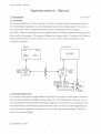
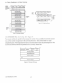
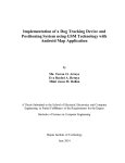
TheN-body Simulation In a Virtua l Universe is a system of procc'ses which compu tes and displays a
o,ct of interacting movmg bodies on a three dimensional head-mounted display svstcm. There arc two
d1ston<t processes which arc responsible for the intcracuon computation and user mterface,
repectively. These two processes may run on separate m.schones, and they commun1cate using a protocol
hbrary bu ilt for this purpose. The system is illustrated on thc figure below. This mdnual w1ll thereforc
dc;.<:ribc each of these three major pieces In turn: the user •ntcrfacc, the protocol library, and the
simu lation comput,,tion.
MasPar
P•xet·Ptanes 5
OPU
ACU
,_,
....,.,
CZ~n'l!I.!~O'I
•
~
........,
..
--a,eG.l...ar.or
QOirC)oJl.wr$
""'""
I
I
~
cen1unon
DEC
>
5000
'
jason
Sun
4/280
polhemus
con1roller
~ ~t
.,..._
........
lh.et trt~.:.
.....
".
rsound
mac
'-----
'
~-
itlel!<"'ace
:.arGw.ar•
y,,..l,IOAI
Vf'I"-'9'U
1.2 High·leve! design iss~~ts
The ;tatement of the project already dicta ted the divis1on of the system into the separate simulahon
and user-interface
proc~'SSCS.
Brcakdo ...ms beyond this were up to the discretion of the team. Since it
wa> deemed likely that severa l different simu lation programs would be b ui lt, we wNc also g iven the
r~'quiremcnt
that the communications protocol be made explicit. However, we also recognized right
away the need for a standard set of routines to use to actually implement the protocol. Th1s is the
purpose of the protocol library.
L.1st Modified: 3/17/93
\n '-·body Somulallon on
~
Virtual t;novcr:>e.
Tht• HMO interface rcquorcs support tor the various onput •nd output devoces .lssoci.lted woth it.
.or~
fortuna te to already
h~vc
access to several libranc; of s uch routines created
her~
w._.
a t Ui\:C There
,>rc several lower -level libraries whoch arc responsible for the ga thering of tracker pos ition and
button-press data, the convcrsoon o f the position da ta onto d offcrcnt coordina te systems, U1e ou tput of
prt'<lcfoned sounds, and the dosplay of 3-D primllives m
>~•'«'().
In addition, there is a library which
handk':> the updating and control issues associ.,ted woth ''lflual control panels contaoning buttons,
doal~.
and 'hders. These libraries proved essential in somphlyong the desogn of the user-interlace code.
·rhc dc•ign o f the communications protocol provtxltu be a ca talyst for dete rmi ning the exact nature of
whdt may or may not be done by either the user in te rface or s imulatio n. W<! wanted a gTeat dea l o i
t1t•xobolity in what sort of simula tions could be implcmrn tt•d, whj le s till having a user inte rface that
madt' sense f<>r each kind . In trying to determine the exact na ture of the exchanges involved, we found
we were eother limiting one 'ide too much, or else we were provtding the opportunity for one side to
confuse the other or the user. The ro.1d to the pre>ent >etup "~"long and bumpy.
The nutu re o f the simulatoon at first did not seem too om port,1nt. We were p rovided with a simple,
baste n· body simulation on the Maspar which seemed to provide reasonable resu lts. We were also
,,dvosed to use a solar system model as a s imple test case for the simu lation. We made o ne of the fi rst
ICSI ca~• even simpler: one small body o rbiti ng anoth('r large one. This immedia tely showed us that
eother: our simulator was much too inaccurate for the model, or else that the model was too precise for
the gwen simulator. Tho> issue was one which led us tO the tdea of supporting many dofferent kinds of
• •mula tors, with the general n·body simulator being on one end and the orbita l body ephemeris being on
the other. Ou r support comes tn the way of feature sets a nd havi ng two distinct sets of bodies with
different featu re sets. This Is discussed in the Pro tocol
~cc t lon .
Thl' C programming language os used for all parts of the system with the exception of the calculation
rout ones wntten for the Maspar. These routines arc in mpl. the Maspar C-likc parallel language.
1.2J Effects of Design on Tt;sting
O ne of o ur goa ls from the s tart was to be able to test both the simulation and the interface sepa rate ly.
Bl'Causc each is a separate program and all the communication is done through the p rotocol library, It
was easy to create simple front or back-end cndc to test the ;omul ation or user-in terface, respectively.
I 2 2 Effects of Design on Assembly and lnll:gration
The fcatur('-()ril'nted nature of the simulation means that il the user-interface doesn't yet have code
implemented for a certain feature, we can simply declart' that the simula tion docs no t support that
L.1;t 'vlodified: 3/17/93
2
fca llln.'. This makes it easy to run wuhout ccrt.lm
fc~tur('S a nd
only ha,·c to worry about them when
they tx'Come implemented, no t befo re.
1 3 Com mon Data Structures
Several c(lmmon data structu res arc ust.'CI throughou t the diffcrent pieces of the system. The purpo~s o f
these arc described here. The complete definitions for the data structu res may found in th<' mcludc fil<'
' nb typcs.h' . which, li ke all the others ml.!ntion<'d here, arc io und in the mai n include directo ry.
The data whoch describes a body is kept in o ne of the follo wmg structur1.'S:
t.ypedef st r uc o
_body_~y;>e_
XYZType posi = ion:
XYZTy?e velocity;
~bCo~orType co:o~;
~'!>Float
c!'large;
XbFloat. :::.ass:
!-<:bfl o at.
~:a diu s;
Status!ype s cac. us;
sody'type ;
cypcdef struct _body_list_ty pe.
XYZ.Type ;ttpositio:1 :
XYZType
;ttvel~c it y;
NbCo l o rType ' color;
Nbfloat. • c ha~ge ;
Nb Float · r.a s s;
NbFloa t •radius;
StatusTy?c •st.aLus;
'30<1yListType;
Thc;c two types are necessary for performance reasons. The ftrst structure is good for passmg smg lc
bodic~ around .
However, the S<'COnd is better orgamzcd for mo'i ng around data for sets of bodtcs. This
i> because the individual fields a re often shu(fled a round by themselves (position primarily), and thus
'irrelcve nt' data is not interleaved in between and moved around as welL In addition, this Stntcture
allo,vs Stmulatlons that do not care abou t ccrtau1 properties (such as colo r) avoid allocating space for
them.
The sta tus field above is used to inform the simulation af a body is new or disabl t.'CI. In addition, the
user interface uses this field to keep track of the selected , ongin, and attached-to bodies. The macros
CLEAR_STATUS, SET_STAn.;s, and CHECK_ST ATUS are pro •;dect for manapulating statu~.
The follo wing structures keep track of info rmation about the stmulation and display settings:
L.lsl Mod ili('Ci: 3/17/93
3
An '·bodv S1mulauon m a V.rtual Univer!>l'.
typedef
char
S~Lucc
_law_type_ !
•!aw_name{t.AW_NANE-_SIZ~ l:
unsigned cha" num_parms;
Nbf'loa t pa rm~ ( MAX NU!-1 PARMS I :
Nbf'loac max parrns(~~X=NVM_PARMS);
Nbf'loac mi~ parm~[MAX_NV M_?ARMS);
La·.... :ype;
cypede=
s~ruc~
_scenario_Lype
unsigned char num_laws;
~ wType
:orce_law(~~~_LAWS J;
uns igned char selected lav.t;
SampleType sample_ratio;
TimeS ~epType
~ime_step ;
int actached to:
int origin body:
Scenario't'ype:
The hm•ts on the law name sin• and nu mber of parameters arc defined in the file 'nb_lim1ts.h' .
lnformahon about ranges f(>r vanables other than law parameters dre kept 1n the structure
'RangeType'
rhc following stmcturc
i~
used to keep track of the feat ures s upport by a simulation:
typedef scruct _!oatu=e
shor t :nax bodies:
short ~n:bodies:
short fixed bodJes;
f'eatu"eType feature
i~fo_type _
Feacu ~einfo7ype: -
S£751;
set~NU~ f'EA7~PE
teatureTyoe world ~;a~uces;-
-
The set o f features is defmed in ' nb_fcatures.h'. Also included in this file arc the macros
CLEAR_FEATURE, SET_FEATURE, and CHECK_F'EATURE for manipulating the d iffere nt feature
sets. A comprehensive description of the different fcd turcs
document.
LdSI Modified: 3/17/93
m~y
be found in the protocol section o f this
Implementation Manual
2. User Interface
2 1 Oyeryiew
Carl Muella
2.1 .1 Introduction
Tht.> I rMD interface immcro;es the user in its d isplay, and thus regular keyboard
i ntcr~ction IS no
longer
pracucal. It was thcr~forc n~quared that all interaction b~ rontrolldble through the HM D m tcrface.
Gaven only a 3·D mouse and a low-resolution stereo display, the only practical control method that
seems plausiblc is a system of virtual control pancls, menus and tools. Several of the interface libraroE'S
Me d~agncd for supporting ccrtam virtual tool o~rations such as 'grabbing' and 'flying.' Another mon!
recent library supports control pa nels with buttons, slid ers. and d ials. From consideration of the
s upport we had, of o ther p rogra ms' virtual interiaccs, and of many hou rs o i thinking, designing, testing,
and
rcd~sagmng,
we came up wath the interface presented in the User's Manual. Though there arc stall
m•nv optimizations aha a could l>e made to the antcriac~. the desagn presented is relatively complete ,
Usmg the libraries, many of the challenging implementation assucs of the interface are solved.
H(lwcver, certain important
as~ues
remained. Whc11 weanng a HMO, it is desirable to keep the
daspJ,\y u pdated contin uo usly in response to user movcmcnh. Any sluggishness or g litches an the upda te
te nu s to annoy the user or <'vcn ca use 11a usea. 'l11e first issue of concern was therefore whether it was
~vcn
possablc to update a large number o f moving bodk•s an r<>a l time. This is discussed below.
The nccessaty to do certain system 1/0 operations from the user interface (such as saving the current
setup 10 disk) would prove to be a challenge since there as no guarantee of how long such o~r,ttions
maght take. The present system an fact will pause and not update the display while such .Ktions arc
occurring. Attempts 1verc made to avoid this, however none proved e ntire ly re liable.
2.1.2 Brief Description of Various libraries t.:sed
I he libraraes used by the interface are as follows:
• pphigs: responsible for display of graphic pnmitaves on PxpiS.
• trackerlib: takes care of finding position and
oncnlatior~
of tracking devices.
• adlib: keeps Jrack of push-bulton de1~ces (among ot hers).
• vlab: d<>als with many co mmon
o~ratio11s
such as kt:cping track of different coordinate systems
and implementing certain basic tools such as •ny· and 'grab.'
• soundlib: hand les the output of a set of predefined sounds.
• text: uses pphigs to display character strings on PxpiS.
• ETK:
L J SI
hand!~
interactions dealing with control panels.
Modified: 3/17/93
5
An '·body Simulation on a
Virtu~)
L:r11verse.
2.1..3 Description of ETI< Toolkit Routines
Smcc the ETK library
i~
rcspon>iblc for a good dc'.il (>(the implementation, we give Wm<' special
Dtlcnlion to its fu nctionality. Using this library, 011e ca n define control panels which may contain a set
of buttons, dials, sliders, and displays. The tools arc described to the library by pointers to thei r
graphoc structures, descnptions of their sizes and placcme11ts, and routines to call when they are
.1c11v~tcd.
ETK is then rcsponsoblc for the p roper display and manipulations of the tools themseh't's,
opera11ons dealing with the control panels as a unot <for example, mo,·ing the entire control panel
around), ca lculating the scaled values for the tools, and calling the call-back routines when necessary.
The ca ll· back ma y then take care of any add itional graphiC or data updates associated with the
operation o f tha t tool. Thus, for the most part, the description of the user-interface implementation
lx>ib down to describing chc layout of the tools .111d chc I:TK call-backs.
2 2 Layout o f
the Intedacr Codg
Carl Mueller
A> dt..·:.cnbed on the User's Manual, the mterfacc parad•gm r('voh·e:, around the use of control panels and
10ob. Thus most of the user interface code is concerned w1th the setup and management of control p.1nl'l"
and thei r associated widgets, and with the handling of tools. Undcrlymg these routines arc a varkty
o f ~upport funclions 111 vario us fi les. The code files arc o rganized in the followong manner:
tFTI( '-P<I.ale panetsl
l.a;t Mod ified: 3/17/93
lmplt'mentalion Ma•wa/
2 3 Dat.a Structure s and State Informatjon
Curl M uello'r
Th1• d~sign of the user interface data structures wou ld prov<• to be a large and complex issue. The ETK
call·back routines arc passed a
sir~gle
user data va ri.)blc, and yet the rou tines must be Jblc to change all
of the user interface st,He. Th<•re .trc several w.•ys to handle this problem.
f1~1.
one could simply declare all the state infonnahon 1n global structures. However, this solution
vtolates the prindplcs of structured programmmg and can castly lead to rn<'l>Sy code. We chose to avotd
ttm route as much as pos~ible.
Another solu tion would be 10 put all of the e<1mmon state informailon in a single structure, a poilttcr to
which i• then passed to the call ·bacl<s. While this solu t1on can dlso lead to somt' of the pitf,1lls of
glob.• I variables, careful programm1ng practices can avmd most of them. If the data Mructur<'S within
the >tructure are kept organ1zed and common routines are used to access them, then thi~ scheme wdl
pro,·e serviceable. In fact ttus IS the organization we chose. The remaining drawback of this chotec is
that coch time the large structure is changed. nearly cvcrythmg must bc recompiled.
The third solu tion avoids this problem and, in ndd itlon, tS the method of choice for future
1mplem<:>ntations of th is system. Instead of defining alithe sub-struclllrcs with1n the main structure,
unlv define pointers. F<lr the sake of prototype checking. these pointers should all be to un1que types.
however the types they point to arc !!Q1 fully d=nbcd by any global include file. Rather, the variou,
sub-~tructures
poi nter~
are defined
tn ~parate
files which arc only mcluded by the routmes that usc them. 1he
in the overall structurc must then be cast to the correct type that they really point to.
llcre ts a summa ry of what tS contained in the large structure named ·u ni verscType':
• scena rio, range, and feature data
• body data and the default body d=riphon
• mformation necess.uy to properly display the bod1cs'
what is the current transformation on the bodic~?
are vectors being shown?
are disabled bod ics bci ng shown?
• whether or not the simulation is currently alive
• the current major mode (world edit/body cd it/run/>toppmg)
• detatled control panel information;
what arc the current and previous panels?
pointers to the panel's ETK structure, as well as pomters for all its widgets
• tool
i nform~tion:
Last Modifi(>d: 3/li/93
7
-\n ' ·body Simulation m a \'ortual l;m,·cr!'e.
what a re the current and previous tools?
what arc the tool pph1gs n,1mcs and important
pph 1~~
aJdrcsses?
• tl·xt pa nel in formation:
wha t set o f strings arc being displayed?
what are the pphigs add rc~ses fo r these strings?
• numenc slider informauon:
what variable
IS
bemg mod1fted?
wha t are the slider ranges for the va riable>?
wha t are the bounds for the variables?
• other mise infom1ation:
wh1ch user? has he quit?
Thi' 1s the 'global' state informat1on. and u is definl'Cl m the include file 'nb_UI_ typcs.h'
~lost
other
state mformation is kept in the tool or button call·bad. routmcs. For mstance, the fly tool routine itself
t..ccp:. track of whether or not1t is currl'ntly e ngaged .
!'here are a small number of g loba l variables I hat arc not included in the universe structure. 1l1ese
111clude the vlib-dcfincd globals and the strings which con tdin the entry, scenario, alld configuration
f1lc names. In the future some of these should be incorp<.>rat<'d into the universe structure.
2.4 User Interface Code SprdUcs
2.4.1 Initializat ion
Carl Mueller
Thl' file ma in.c includes the steps for initializatio n as well as the main loop. We now descnbe the
seq uence of events that occu r during initialization tim1':
• parse command-line options
• check existence of data fil<:>s
• imtialize various fields m the universe data structure
• initialize vlib, tracker, sound, etc.
• read in pphigs data (fonts, ctc.l
• initia lize all control panels and ot he r g raphk• ObJects
• initia lize the GP call-back rout ine'
• initia lize the simula tion
• enter the main loop
• Th1~ routine hand les the rap•d display of the bodies and 1s discussed in a later section.
Last Modified: 3/17/93
hnplcmcntatiorJ lv1anual
2.~.2
Main Loop
Carl
.lt!udl~r
Th.- mdln control loop 1ncludes the following stc~:
• check If a simulation mt-ssage has arnvcd
• prOCl'SS mput for each user: •
read the tracke r and update the ust•r tr.m,lnrm matnces
read the p ush-buttons
update the users with respect to moving bodies (if necessary)
call the ETK control panel rou tine for the active panel
if no panel action happened, call the active tool function
il no tool action happened, sec il the tool panel wa;, toggled
• update the GP call-back
• sec 11 there's any termmal input
• update the user's display
• At the moment, support is o nly provided for,, single user. A fair number of changes would .1etua lly b<•
necessary to support more than one user, dcsp1tc '001l' of the support al ready included.
2.4.3 J.:TK·related Routines
Most all of the functions provided by the user inte rface are implemented either through ETK call-backs
or through tool calls. The selection of tools tn fact usually occur!> as a nesult of a button call-back.
Dchnnions of the ETI< control panels and
the~r
w1dgcts occur in four different files:
• •vorld_cdll_init.c
• body_cd it_mit.c
• tool_pancl_i nit.c
• tcxt_panel_init.c
Each setup routine p roceeds as follows: all the ETK widgets a re declart'(), they are thc11 s roupcd into
their assoc.a ted panel, and finally the actua l pi~Ct'mcnts of the widgets are de termined.
In Jddihon, several ht>ader fi.lcs arc mvolved:
• etk_inn.h
• world_edit.h, body_edit.h, tool_panel.h, text panel.h
The former includes enumerated type definitions which allow giving all the butlons names. The latter
flies mclude the function prototypes for all the call-backs.
The ca ll-backs themselves are defined in one of the lollowu1g hies:
L:tst :viodified: 3/17/93
9
\n :-.. ·oody Simulation m a Vutu•l Umvcrse.
• world_editing.c
• body_cditmg.c
• tool_pa nel.c
• tcxt_pand .c
• slidcrs.c
ThtS organization works well for wtdgets that are found onlv on one single p•ncl. However, some oi the
wtdgets arc located on both the body and world editing panel>. The slider related call-backs are all
found in slidcrs.c. For button> >uch as 'go to body', the call-bac~ were placed In "'Orld_ediung.c.
If o ne wa nwd to add another bulton to one of the cxtsting pa nels, the following stl•ps would be requi r<•d:
1. Create a pplugs icon for the button and make gurc 11 ~cts loadt•d by one of the routmes hl
pph•gs_objccts.c.
2. In etk_init.h upd•tc the number of buttons and thctr enumeration for the appropnate panel.
3. Add thc ETK call to create the button in the apprt>pnatc mit file, as well as the code to posltton
the button properly.
3. Write the call -back routine itself and place it in th•• •ppropriate file.
2.~.~
Tool Routines
The tool functions are what control the actions of the various tools the user may usc, including the
~lobal
Oy, grab, scale, and <elect tools. as well as thc more >pcctfic add, posttlon, radtus, and ,·cJocity
tools.
Dcftniltons of these routincs arc fou nd m o ne of the two ftlt•s:
• g lobal_too ls.c (with header file global_tools. hl
• cditing_tools.c !with header file ed iting_toob.hl
The tool pphigs structure names are kept track of in the tool mformation in the universe structure. Thiarray is actually set up in pphtgs_objeciS.c. Also kept m the tool information structure arc pphigs
pomters to display list clements that must be updated when usmg a parttcular tool. Finally, the tools
Me cnumcr;~ted in nb_ui_types.h.
2.4.5 Miscellaneous Routines
Tht·n~
are many files contaming various support and service routines. These arc described here.
The file gp_stuff.c contains, m addition to routines which talk to the GP call-back(~ below}, routines
whtch arc used whenever a body p.uamctcr must be modified. Other routines may IC>Ok at the values m
the body list, but shou ld not modifv them dmxtly, o r else the bodtes may not be displayt>d properly.
l.~~t
Modified:3/17/93
10
Implementation ,\Aanual
Th(' file s im_stuff.c contains
for th~
most part routin<:>s to talk to the simulation. In addition there arc
ro utines to properly S<!l up the control panels whcncv,•r a nuw sce1,ano or s1mu lntion IS Joodcd.
Th•• fi le OO<ly_select.c contains a package of rouuncs for dealing with the currently selected body. In
addition there is a rout me named S<!lect_update_panels
d~pcnding
'~htCh
updates the st.uc of the control panel
upon the statc of the S<!ll'Ct~>d body.
Some Important routines, which are currently located in inappropriate files for thc most part, arc:
• Switch_To_Control_Panel: remembers the last panel, toggles up the given panel.
• Switch_To_Tool: remembers the last tool '"'d sw itche-s to the gi ven one.
• Switch_To_Strmgs: <witches the text pancl dl>play to show the gl\•en set of s tnngs.
Tht'rc are several files conta1nang o ther vanons suppr<lrt routmes:
• find_filc.c:
gct_file_list: gets a list of files with a g>Ven extension th<1l ,1rc found in a g iven directory.
• find _tags.c:
get_tag_list: parse the configu ration file to find (Ju t the names of the simu lation tags.
• su pport.c:
Parse_Command_Lmc: mterpret command line options.
Usage: print out a message dtsplaying proper command usage.
Handle_Terminal Input: ha ndle cha racters from the keyboard.
• utils.c:
RGB_to_HSL, HSL_to_RGB: conv<•rt a color from one system to the other.
ftx_bounds_float, fix_bounds_char: make s ure a
v~lue
is within limits.
bascname, dimame: parse clements from a fi le pathname.
lookup_stnng: finds where a string is in a
li~t
of s tnngs.
The re maining files which have not been mentiOlled yet contam imtializallon rou tmes:
• univ _init.c
• vli b_init.c
• etk_init.c
2.~.6
Description of the CP c~ll-b~ck
As mentiOned
befo~,
Carl Mueller
it is impcrath·e to update the display o f the moving bodies m real time. The
pph igs mterface to PxpiS is not very appropna te for changing the positions of many mdcpcndent bod1e>
Last Mod ified: 3/17/93
II
An ' body Stmulabon m a Vtr1ual
l,;mn~rsc.
at onc:e. This is because of the communica tions bottlcncd. between the Pxpl5 host and the graphics
proco.?Ssors (GPs). We found tha t by using regular pphigs updatE'S frame rate s lowed down appreciably
when changing as few a s one hundred bodies. We therefore had lo find a better way aro und this u pdate
prllblcm. T he solution proved to be w hat i~ rcfcrrc<.lh' ~5 the GP call-back.
The update problem has to do with the amount of data that 1> sent from the from host to the GPs.
Under pphigs, a single sphe~ update sends a relatively large sphere message which includes a Mde
set of infom1ation about the sphere. However, during run mode, the only
v~lue being
changed is the
s phere' s position. We can send just the pos ition inform.1tio n to the CPs. This is do ne ustng ROS routines,
the Ri ng Operating Sys tem whic h pp higs itself is written over. Then, by inserting a call-back structure
into the pphigs disp lay-list, the sphere in fom>at i<>n can be read by the call-back code and used to
dlr<'Ctly call the GP low-level draw sphe re rou tint' Th1s mNhod allows several hundred spheres to be
upd•ted without approoable I<>'>~ oi frame rate.
The cr call-back is independen t of the rest of the ""'' r•ontcrface code. That IS, it Is comptled
separatdy to run o n the Pxpl5 C Ps, not on the fro nt end. It is possible for this code to esta blish its own
data s tructures and event set up cvenl-hand iN routines ouch thdt it ca n respo!ld immed iately to
mc>:.ages sent to tt. We have decided !hen to 1mplcmcnt an mterface with thc GP ca ll -back to hand le
the following actions:
• send a new set of body po:.ttior<~ to GP
• send a ne\v set of vclocttil"> to GP
• send a new set of r,1dii to GP
• send a new set of colors to GP
• send a new set of statuses 10 Gf>
• change s tatus o f displaying vectors or d isabled bodies
To speed up as much as possible the front end side, we chose to hav<:> the ho~t send the new infom1ation
tn the form of a single message to the first GP. Thts GP then distnbutes the information out to the othcr
CPs m the ring. However, thts also limi ts the number of bodies smce the Gf> input FIFO os of hmJted
StZC. If the current limit o f 500 bodies ever proves too small, then thi s interface w ill have to change
somewha t. The change wou ld require ha ving the host (i ns tead of the first GP) d is tributc !he messages.
The design of the GP call-back proved to be cl>allengtng. Th<' ba:.ic problem is the uncertainty of the
nmmg between u pdating the body in forma tion and displaying tt. When a Pxpl5 draw frame command
tS ISSued, it will actually be some ttme before the GP call·back code is actually called. In the mean
ttmc, we might already have a new set of body data to send down. The solu non tS to usc a queue and a
set of semaphore va riables between the message handlers and the d ra wing code.
Last Mod ified: 3/ 17/93
12
lmplt menlatron Manual
All thE! GP call-back-related front-end code is self-containe-d m the gp_stuff file. Thi s w11J enable
cas.cr portabil ity should to
opportu 1~ity
arise to switch to a diffE.'rcnt graphic architecture.
Carl Mutllt'r
2.4.7 Maintaining Continuous Updates
Since some of the functions mvoh-e systt>m 1/0 operatum~ '''lth no guarantffii response time, some
thought has been put mto how display updatt>S could be mamtaincd. The method chosen involvt>s the
usc of the Unix interval timer mterrupt routine to generate a SIGA LRM. This s1gna l is then caught and
use-d to call a speda l display update routine. This handh:r w ill do a subset o f the events handled by
the main loop: those direct ly related to updating the display. Since no user interaction is possible
dur1ng this time, the cursor Will l'C changed ro a rradit10nal clock-like icon ind iCatmg that the user
mu't wdit.
To dVOid contlict with the main line routint>S, this handtt'r i; only enabled when possibly long
operations may occur. The particular operations where this handler is necessary arc the load scenario
file, save scenario file, and load simulation operation,
·1hcse handlers arc defined at the end of the main.c file:
• rdrcsh_init: sets up the refrt>Sh interrupt handll'T
• refrcsh_on: turns on the refresh system.
• refresh_off: turns off the refresh system.
• refresh_int: thl• •ctual interrupt handler.
Unfortunately, these routines proved to be somewhat unstable, sometimes resulting In program lock-up.
The p roblem SC'()m5 to invo lve collisions of interrupts. l'xpiS generatt>S an interrupt whenever a message
IS
sent to the host machine. While this message is bemg read, no other interrupts should occur. We
~ttcmpted
to set up the clock umer to avoid such coll1sions, and yet they still managed to occur.
Thus by default the refresh system is disabled
~t
startup. If one w1shes to
cxperim~nt
with the refresh
system, then one may give the ·-r' option o n the command line to enable it.
Adam
2.4.8 Scenario File Implementation
Dugga>~
The scenario file for the nbody application is an ASCII text fill' defining the complete state of the
Simulation at the point the user saved it (see the nbody user manual for a complete description)_ Its
ASCII format (as opposed to binary) makt>S it simple for the user to edit the file, or even write his own
from scratch. Due to the rela ti vely loose formatti ng rt-quircments o f the file, a Lex and Yacc parser
Last Modified: 3/17/93
13
An '- ·body
Simul~tion
in a Virtual Unovc>rse.
system was chvscn to read it in. A corwcoHoon• l C parser wou ld 'lXluire a fair amo unt of logic just to
hand le varying whitc
the
~pecofications
~pace,
whereas the Lex parser
take~
ca re o f this automatically. Also, changong
of the fole are much >impler '"hen implemented this way versus manually. For
documenta tion on the use of Lex and Yacc, ~ the Unix Programmer's ~tanual, Supplementary
Documents I (chapters 15 and 11>).
Lex and Yacc are tools sp<xifically designed to aid progTammc rs In the generation o f input parsers. L<'X
os a lexical analyzer which allows one to define regular expressions descnbong prcces of input d;ot,l. It
tran~lates
each piece into a token which is then processed by Yacc, the scmanhc parser. Yacc uses a
context free grammar along with a set of actions ((source code) to process the input. Both the Lex source
fil e and the Yacc sou rce file arc run through their respective ct>mpilcrs to generate C source files.
Since m ost of the da ta from the sccnaroo fole is o i the form A"YUlorrf numerical_t>a/uc, most oi the rulc•s
took this same form. The actions taken on each of these rule onputs arc defined such that all of the
input data is condittonally placed on the p roper data structures, as the simulation may not allow
certain fields to be changed. Additionally, the rules
h~d
to be defined such that they would allow
o nly specific keywords and data within a body declaratio n. Thos da ta may come in any o rder, and
there is not a set amount of it. Yacc's rccu rsove rule defonitoons make handling variable amounts of data
>rmple. A simple rule takes care of checking most errors as the file is read .
2.5 Changes for the Future
Carl Mud/a
There are a few major changes that we wis h to implemen t it\ futu re versions o f the code:
• Change the un iverse data structure as mentioned in the state section.
• Move the functoons around to different files:
All functoons which update panels o r swotch tools should be together
Perhaps the re should be a file of ETK call-backs whoch are common to several modes.
• There arc severa l o perations that are defi t~ed repeatedly. These should be consol idated into
appropriate functions. An examples is deriving the average eye transformatoon.
• The placement and sizing of control panel p.>nl'l widge ts perhaps can be made easier to modofv.
2.6 Testing
Due to the large number of functions, tools, and fea tures available in this system, there p roved to be no
very straightforward method of testing. Also, being immersed in the HMO means that one cannot be
onteracting with the console at the same tome. As a result of these factors, o ne must enter the system
and very carefully test out each button, shder, dial, display, and tool under various conditions. Doons
thr> properly
~ISO
means having a variety of simu l,ltions a variable which allow doffercnt sets of
Last Modified: 3/17/93
14
feature:. Th>S pi'O«"SS can be rather hmc-ronsum.ng. It" bc>t to have another pt'rson nearby to make a
note of any ddu:u~nCles found s.nce makin11 >nch n<>tl"- whilt• wearing a head-mounted di~play can be
awkh•Jrd.
Last Modified : 3/ 17/93
15
An N-body Simulah<>n m ,, Vtrtual t;niverse.
3. Protocol Implementation
Mark Pam;
3.1. Puroose
The project specification for the Nbody SimulatiOn in a
V ~rtua l
Universe expli citly states that the
simulation and the user interface run as separatc processes .1 nd communica tt! over a well documented
protocol. The protoco l allows the user the fle-xibil ity of writmg simulations lx·~idl's the one providro
w1th this package. Using TCP/IP on a local area ethcmct allows medium bandwidth communication
w1th reliable deliverv. Since TCP /IP provides the performance needro by th1s application, protocob
r~-qumng more compl(.')(
semantics, such as UDP's unrchable and out of order delivery, can be a,·oidro.
Other alternatives such as pipes or a different type of network were not considerro because of thetr
un.wa1labi lity in thc dcvclopmcn l environment.
Thl? protocol is implemented
Vax
(l,;ltrix)
a~
a library (libnbp.a) ava~labk on the Su n (SunOsl, DEC (Uitrix), and
platforms. LQOking up a process entry in a proc.·ss configuration me (see Prrx:cs:;
Configurtllion Specificauon in lh( User's Manual Apptndlx}, starting up a remote proces~. dcterrninmg
the set of features supportt-d by the Simulation, convcrtmg data bet":(.'('n the architectures of different
machmes. and cxchangmg conf1gura11on and body intorrnat1on arc all suppo rkd by this hbrary. Al l of
thc!)e features <.1re described in more detail below.
Tlw protocol specifica tion includes a descri ption of features, a method for allowing the simula tiOn In
'pcc:1fy " 'hat features it supports, a description of the me5sage sequences, a dcscnption of the expectro
Jata conversion, ,md a dc-<r1pt1on of the mcss.1g<' forma h .
3,2, features
Suppo rting simulations w1th d1ffcrent sets of features wa:. a primary goal of ou r dcs1gn. We wanted to
; upport simula tions where the bodies move in orbits <•nd the user can't affect anything but color and
rad1us of the bodies. We also wan tro to able to support n·body s imulatio ns where the user may alter
the velocities, masses, charges, pos1tions, and radi1 of bod1cs as well as add and delete them. Further,
1vc want('(! to support SJmulahons that had both types of bod1es, with the masses of the orbnal bodies
affecting then-bodies but not the reverse, and with the user mterfacc able to cha nge different sets of
properties of the bodies of each set. To do this we decided to provide a wide range of tools and
opera tions on bodies, force laws, and Ihe properties of each and to allow the simulation to specify
wh1ch of them it supports. Further, to support the third case above, we decided that we ncroro
mult iple body sets: alpha bodies and beta bodies. This specification occurs by an exchange of features ill
the lnit Mode of the protocol. Once these features are
the S1mula11on does not support and runs as usual.
Last Modified 3/17/93
16
exchang~>d
the user interface disables tools that
lmplcrnenlation Ma>!lta/
3.2.1. Feature Sets
As 111d1cated above two S<!ts of bodies with different
featurl'~
a rc al lowed. The simulation may specify
,,n alpha S<Jt o f bod ies, from which bod ies may l:>c nci tlwr added nor deleted. This set is intended
prunarlly to contain tho$<! bod1cs where there is a fi xed cquat10n associated with c.1 ch body. Since thi'
one to one correspondence c><i\IS, adding bodies hardly seems practical, and dclchng serves little
purpose other than ncmoving that equation from display forl'ver. However, one can enable and disable
the<e bodies as described bclo •v. The beta set of bodi~ may ha,·e bodies added and deleted (if the
fc.uure is set). Both S<!ts of bodies can support any of the features and each set has its own feature hst.
At (:on figurat ion time, the ~imu kHIOII tells the user interface how many bodies are in
H~rc
~ach
set.
the fea tu res are bro ken down into groups wi th an ovcrv1cw of the feat, res in that group followe-d
by notes about individual fl'atures as appropriate. 'lt>tc that turning on and off features is supported
through the usc of macro' 1n nb features h.
SET rt:ATURE Calpha_fea:u=es,
.:Hi\.'-:GE_~IA$3,
NB_CN!
turns the CHANGE_MASS feature
on.
CLE:AR_FEATUR£ (alpha features!
clears th<' cnt!Te set o f features for alpha_fcaturcs.
SET_FEATURE ( a l phd_fe~~~res , CHANGE: MA SS , NB Orr!
tu rns off the mass feature.
The feature flags arc discus~ below. The ilag name used with the macros is specif1ed m parentheses
<e.g changing mass ICHA\;GE MASS))
3.2.2. Turning Bodies On and OU
The user interface supports two ways of choosing to include bodies in a particular Simulat ion. Add ing
<ADD_BODY) and deleting <DELETE_BODYJ actua lly change the list of bodies in the simulation,
il1crcasing or decncasing the number of bodies sent between the Simulation and the user Interface.
However, thenc may be models where a deleting a body (and thus rearranging the list) may have
undefined consequences, such as deleting the fifth body m a !>Qiar system simulatiOn. Do all of the other
bod1cs move up, with Sa tum taking )upiters orbit? To allow turning off a body without rearranging,"
hst disable (DISABLE_BODY) IS provided. Dis.1blcd bodies rema in in aU lists of bodies but they arc
not displayed. The simulation is free to interpret thi s d isabling as It sees fit (provided that it keeps
the body in Its li sts) or to ig11orc the featu re altogether.
Note: ADD_BODY and DELETE_ BODY arc ignored when they occur in the feature list for the fixed
body set.
l.a~l
.'v1odified; 3/17/93
17
An '-·body Simulation 10 a \'mu,ll l;mver«'.
3.2.3. Changing Body Parameters
A simu lation may choo«:" to diiOw the us<:'t intcrfa,·c to change any subset of the body parameters. If a
Simu lation doesn't all01" the user interface to change a p.~tticula r body p•ramctcr it must provide the
values itself if they arc of any concern. No modification of these fields. either by t'dit ing, loading, o r
defaults may occu r as a result of the user interface J! the simulation hasn't cn<~bt t'CI the feature. The
features arc listt'd below. Turmng one of them on allows the user interface to support the achon.
CHANGE_ MASS
C HANGE_POSITION
CHANGE_ VELOCITY
CHANGE_CHARGe
C HANGE_COLOR
CHA:-:GE_RADIUS
3.2.4. Caring About Body Parameters
In additiOn to permitting change to body paramclt'rs, there "a question of concern for the values of
parameters. Two of the body pa rameters merit special consideration. Color and radms are v151ble
properties of the bodies which must exist. If the simulation d isallows changing them. it must providc
default v•lues. Further, color and radius arl! usually not of concern to force law calculahons or
~1mulat1ons
but there are ca<;CS, ~uch as collisions, or a
~imulatJon
of sorting bast'd on color where the
Si mulation may care about thesl! properties. To avoid unnecessary overhead, color and radius are not
uSlhlll y sent from the u<;er interface to the simulation. I fowever, by setting the features SEND_COLOR
J nd/or SEND_RADI US the Simulation can indicate thil t the user mte rface shou ld send thesE:'
propcrbes as '''ell.
J.l.S. Changing Scenario lnfonnation
A s1mulatton may choose to allow the modifica tion of the hme step <CHAJ'IGE_TIM ESTEPl or samplt>
ratio (CHANGE_SAMPLE. RATIO) used to calculate and contro l the d isplay rate of body positions.
Further it may choose to s upport mu ltiple force laws as well as adjustable force law parameters. '>otc
that there are no features assocta ted with this since the existence of multiple laws implies the
pcrrmss10n to choose among them ,,nd the existancc of a coefficient implies tt>at it Is adjustable.
3.2.6. Interactive Parameters
In addition to the changes supportt'd during editing mode, the user mtcrfacc supports two actions during
run mode. The user interface may send thrust updates o r ~mple ratio changes up to once per frame of
l.ast M(ldified: 3/17/93
lmplern~ntatzon
Manual
do t,1. A> usua l, the s imulation can choos.: to support these wols by enabli ng CHA!\GE_THRUST
Jnd/e>r CHANGE_INTERACTIVE_SAMrLE_RATIO.
3.2.7. Miscellaneous
Fina lly, the user tntcrface provides the capability of displ~ymg velocity
sesstons and during run mode.
Howcv~r.
vectors during editing
this features is of no use if the the slmuiJtion has no concept of
velocity. For instance, an orbital simula tor may calculate the positjons of the p lanets at time
mcrements but hav<' no need. to calculate the velocity of the planets at any point in time. In such a ca:;e
the Simulator would not enable the Sl lOW_VELOCITY feature.
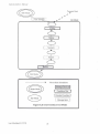
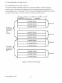
J,.3.;\1essage Sequenc.e
This section defines the expected sequence of mt)ssages and the differen t sta tes each side of the protocol
can be'"· Figure 3.1 shows the possiblt• s tates and the tran,ttions that may occur b./tween them. Both
processes start
tn
lmt mode. passing quickly to Edit mode. Once past the initiallnit mode both procc';<"-
cyclc from Edit mode to Run ~1od<' to PI'('-Stop mode and back to Edit mode dept'nding on the user'; action
and r('Su lting ml'SSagcs s.:n t. It tS also possible to retum to Init Mode o r to exit from Edit Mod~. The
imp lementation of ci th~r process mdy o f cours~: use o ther interna l mod es but the ones listed above nrc
Jll that the simulation nc<.-d b./ aware o f.
Last Modified: 3/17/93
19
An N-bodv Simu lation in a
V~rtudl
Universe.
Simulation
.!.
In it
~~;:-::•::.----~I"'"&;J;;;'S""]I--------........................
,'
,....
Exit
Edi t
·'
-l. . s;:~;i"]
....
!~ -J.~.------:.--- . . . . . . . . . .
'
\ ----~
jj''"&;d't~~·u···d·~·;~"'"']IL.L------""
-"'
P..................r
.....
•
'
I'
............ l..........
I
I
Pre-Stop
P rotocol Messages
---- -- _.,._
Run
--
State Transitions
Program lnitialiUllion
........................ ......]
...::-:.~~~~.~.~~.
'
State Change- Figure 3.1
LolSt Modified: 3/17/93
20
lmplcmenlatzon Mtm:MI
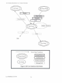
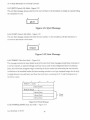
3.3.1. I nit Mode
A~
'hown in Figures 3.2a and b, the protocol proper begms ""th the simu lation ,_,nd ing a CONFIG
mC$><~ge
to the user int<•rfacc. It s hou ld be noted tha t the protocol library begins one s tep before this
1vith the user interface startirlg the simulation as a rt•motc process using the nl1p_r1111 function. Starting
the
~imulation
from the user mtcrface is no t a formal part o f the protocol. but rath<•r an additional
fea ture of the library. The configura tion message spcctfi<'l> a great deal of information about the
"mulatlon. Included in thts m<'!>l>agt> may be the number of bodies in the fixed set of bodies, the
ma"mum total number of bodil-:.. the min1mum number of cnablt'd messages, the features o f the sets of
b<>d1cs (both sets tf both can exist), default color and/or r.1dous fo r the beta set of bod1cs if the USL'I'
Interface can't change color and/or radius, ranges on the properties of each set. the number of laws,
their names, and default parameters a nd ranges. Additionally, defaults and ranges for the time step
dnd <oample ratio may be inciudl'<l. For a d£'scnpt1on of the conditional crea tion o f the CONAG
mt'SS.lf\~
,.,.., the message fomml section below.
After ~nding the initial conftg uration message the s imulation may cond itiona lly
mc~s:•ge
~nd
a BODIES
describing those bodies which cannot be added o r d eleted. If all bodies can be ,tdded or deleted
the message co!\talns zero b<>dics. If the to tal set of bodies Includes a fixed set of bod ies, then at least
tht>M' bod1es are descnbcd via this message. The number of bodies in this case would be the number of
bodu?s in the fixt'd set. In add1tion, if the s1mulation doesn't allow adding bodies in the second
5£'1
those bodies arc included in the BODIES message as well. In this caSt>, the number of bod1cs 10 the
ml'>sage will be tht' maxtmum number of bodies. The properties which may be conditiOnally tncludt'd m
tnt' BODIES message ,1re dcclart'd in the messa.~e formal l>Cct10n below.
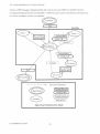
Follow ing the trar•smission of the body message, the us.;:r interface should load in whatever
onfo nnation it may wi~h to about bodies and the scenario ~td tc. Following this, the user interface
should send the simulatio n an Initial SCENARIO message mdicaling the currently selected law. the
number of parameters sent, and. where apphcablc, the lime stt>p, samplt> ratio, and force law
paramt>ters. For more mformatlon o n the conditiOns under which spcafic Items of data arc >ent, set> tht>
me.•.<ttge format section below.
Next, the user interface shou ld sc·nd a BODIES message to the s imulation, w ith the ne wly added bodies
marked as NEW in the status field. The simulation is expected to receive this message and fill in ,,ny
parameters that the user interface isn't allowt'd to change and send a BODIES message back to tht>
<tmulat1on
so that tht> s1mulauon has a fully imhalized set of bodies for display.
Last Modified : 3/17/93
21
AnN-body Simulation in a Virtua l Un iverse.
The transmission of this message on the simulation Side, and the receipt o f the mcs,;.,gc on th" user
interface side cause~ a transition to Edit Mode.
Program Start
, ""
New Scenario
--.C
. ..)
!nit Mode
...............co~·£i. .. . ........l
l"'""'"'"'"'""''"'"·8...............
6
l"'"'"'"''"li~i'i;;:;;"""""""l
.....0 " "'"
''
Scenario
6
'
Bodies
I
0
------ - ---------~
Minor State Transitions
IMessage Received I
(
Condition Met
)
,............................................... ....,
I Outside Condition I•
.......................,
~·~···········································~
.... ~~~g~.~.~~ .. .
Figure 3.2a Simulation lnit Mode
Last Mod ified : 3/17/93
22
lml'ifmenta tlon Man ual
.,
Program Start
' ' ' '' '
...
· · · · · · · ~...: ~·
.,
...
(
I
I
!nit Mode
)
I
Con/ig
6
I
Bodies
I
6
I.....
.....I
·······················
I
·see~·~;;·<>·
6
I
i\Odies' ······
......................
...
1· · · · · · ·
1
c=>
I
..
''
~ ies
I
~di1Mod:1
----------------·
Minor State Transitions
IMessage Received I
~
E)
e
Met )
(.........Condition
____,..,__,.,,____,..
I.................................................
Outside Condition I
~'
I..., ,,,M~~
..~·~·~; ...I
, ,,, ,, g ,, ,,,,,, ,.
Figure 3.2b User Interface ! nit Mo de
Last Mod ified: 3/17/93
23
An :-.-body S•mul,lt10n m ,, Virtual UniverS<'.
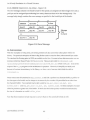
3.3.2. Edit Mode
Once the user interface hns entered Edit Mode. e ither by receiving a BODIES mcS><~gc m !ni t Mode or a
STOP m"ssage in l'rc-Stop Mode, as shown m Figure 3.3b the user performs his desired edits. These
C'd•ts can result in a vanc ty or messages being sent to the Simulation. The BODIES a nd SCENARIO
mcs><lges may be sent 111 any o rder a nd. to leave room lc>r future mod ificatiorl. simulations should be able
t<• n'Ce1ve these commands multiple times. The mesS<'Igcs wh1ch cau_<e a state transition arc START,
QUI T, and ' EW_SCENARIO
The BODIES message co nta1ns the entire list ol bodies. This list indicates the new "state" o l the
bod1es. New bodies are marked as NEW and the s imulation is expected to fill i11 any properties th,1t
the user interla.c c is not allowC'd to change. No indication of deleted bodies is givc 11, no r arc c ha ng•'<!
bod1es marked. The >rrnulation is expected to simply read 1n th1s body list as 1ts new state. The u""'r
mterlace is tTusted not to perform any actions disallowed bv the srmulation.
Tht• SCE:-:ARIO messagl' Indicates a change in some globa l pMt of the sccrorio. 1-'or information on the
fields o f the message and tht•rr cond itional transmission, ~cc the mes.~age format section below.
START·~ a
parameti'rlcss mcSS<l);C w hich chang<><: state to Run .'v1ode o n transmit Irom the user interface
and on receipt at the simulation.
When the user interface IS readv to tl'rminate the simulanon 1t is expected to send a QUIT message to
the Slmulotion . Upon recc1pt of this message, the simula tion cleans up and exits. The user interface
may then exi t likc'"isc or p roceed to Initialize a no ther s1muldtio n.
The NEW_SCENARIO message is a lso a paramcterless message which changes s tate to Init Mode on
tr.1nsmu from the user interfac-e and on receipt at the simulat1on.
Last Modif1ed: 3/17/93
24
lmplcmc"tation Manual
\
\
~
',
\
I........ "· ............'I
,
'
........~.:~... .. ..
',,
',,
',
',,
,
'
ew Scenario
&.......;..;;......;.;=~,=--~
\
I"'BO'dy '(ip;j~;~· ...l
I':::::~~~~~\~::::::,.
'-
......... si ...........,
'"''" J'""''''''" '"
·· ··· ,··· ··· ~P. .... ··· •
',\
\
'\
\
>
,,
,
'
,
I
"
Quit
,
I
..
I
~
'
,,
,,
\
\
''
I
'
.,.
~ - ---
...
_
'
I Bodies I Scenario
I
..... -.. --- ..
\
\
\
\
\
Start
\
I
\
I
-
\
I
\
\
\
\
fu1i1
-----
~
~
----- ----- -------~
Minor State Transitions
!Message Received I
(
______ __ .. ...
Condition Met )
,..........,
,
,,
~
~ Outside Condition I
"·--··---··--..........!. .
.......................
.' ..~~~~&~ .~.r~!. ' .
Figure 3.3a Simulation Edit Mode
Lnot Modified: 3/17/93
i\n N-body Simulation in
Virtual Limvcrse.
.1
''
''
''
''
Bodies
''
''
''
''
,' '
Body Update
''
''
........................
'
'
New Scenario
........................
''
''
''
Sceruuio
''
Stop
''
'
'
I I I t i o t! o ! ! t "
t "
01
o "
I t
Bodies I Scenario
"''""'"'/"""""
........ - -
,, '
''
'
l.........,~'i't''"'"''l
•
•
•
•
•
•
•
•
•
;
''
..........' \ ............ .
) ' 0 •• 0 •• 0 •••••
Start
............
.......... .
,,
~,.
•
------------ -----~
--...
''
''
''
''
'
Minor State Tra nsitions
I Message Received I
(
Condition Met
.....................--......-.............
)
~.
I...................................................
Outside Condition ~
,
. ~· fi~~t· .. 'I
..• ... $ ., .. ... ... .
I..'....M'~~~~·
Figure 3.3b User Interface Edit Mode
L~st
Modified: 3/ 17/93
26
lmpl(mrntation ,\lianual
3.3.3.
R~tn
Mode
Run Mode has some of the more complicated actions ,,s seen in Figures J.4a and b. The POSITIONS
message 1s the only mcssngc that ca n tra vel from the simu l<1 t1on to the in terface wh ile in this mode.
Thl• uwr interface can send THRUST. SAMPLE_RATIO, .'\:O_OP, or STOP messages wh>lc '"Run Mode
To update body positions in the user interface, the Simulation sends a POSITIONS message after every
SA 'VIPLE_RA TIO iterations of the current time step in the >lmulation.
(If
the SAMPLE_RATIO isle'>
than one, the simulation sends the same frame I /SA 'VIPLE_RATIO times). To main tam
>ynch ro niza tion betwL'Cn the user in terface and the simulation, the user interface ack110wlcdg"'- each
POSITIONS message. However, to avoid delaying the updates because o f network or host load we
allow tht' s>mula tion to continu(• ru nning with up to 1::1. unacknowl<:'dged POSITIONS mcss.1ges an trarNt.
If the cap IS ever rt'achro then the next send oi ,, POSITIO;-:s message wrll block until an
ad.nowledgement
IS
r(occrved
The user mterfacc acknowledges reccivro POSITIONS messages by setting the ACK field in THRL:ST,
SAMPLE_RATIO, o r NO OP mt'ssagt's.
THRUST, SAMPLE_RATIO, and NO_OP messages may o nly be sent In response to~ received
POSITIONS message and one and only one of them m•y be sent per POSlllONS message received. li
mC!o>Jg<'S of multiple types an: pending they are proccssro ao follows. If a SAMPLE_RA 110 mcssagt' is
pendmg tranSITUSsion, send it With the ACK field set .lnd disrt'gard any pending TIIRUST messages.
Otherwise, if • THRUST message is pending, send it wrth the ACK field St't. Finally, if neither of the
othe r mt'ssagcs are pending, send a NO_OP (which arc never pending) with tht' ACK field set. Jn
rea li ty, multiple pending messages
1s a
rare caSt' indicat1ng that the user was able to swotch between
the tools for those mes~ge> in the space bt'twt't'n th(• arrival of two POSITIONS messages.
Despite this limitation on the transmission of THRUST, SAMPLE_RATIO, and NO OP messages, it is
Still possible for them to get clumped m transit and, con"~Cquently, for more than one of these messagt'S to
arnve at the simulation dunng the space of a single frame. As such, the simulation is expected to
receive all available messages after each transmrssion of a POSITIONS mL'Ssagc, decremen ting its
cou nt of u nacknowledged messages appropriately. Further, the receipt of multiple TH RUST and /or
SAMP LE_RATE messages should be
treat~>d
as if o11ly the last message arrivro. The earlier scttmgs
should be discardt'd.
Last Modifiro: 3/17/93
27
An '\;-body Simulation in a Virtudl Universe.
F~nally,
a STOP message is hoghcst prionty and of one os sent. any THRUST or SA\<IPLE_RATIO
mt'ssagt's pt'nding transmossoon arc discarded. A STOP mc~-..1gc results in a transotion to Prt'·Stop Mod"
on both the somulatoon and the user ontcrfacc.
~
Stan
,
,,
,,
,,
,
,
,
I
I
I
,
,
,,
,
,
'
,.....' '..........___................)
-
•
I
c.~::.::.?r.::!,:::~r,.,,
I
I
_ Unack_>=lY
I
I
I
I
' ')(
I
''''' i,~;itl~~'s''
' '' '
,............ .
I.......
I
I
I
I
I
Stop
...
Ryn Modc
No_op iThrust
I Sample Ratio
I
I
~
~
M1nor State Transitions
IMessage Received I
(
Condition Met )
-
( ................ ..................)
....~.~~~~.~.S.?.~.~~~~. I
.....................
....¥.~.~s~. ~~~~ ...
Figure 3.4a Simulation Run Mode
L,1st Mod ified : 3/ l i /93
28
)
fmplementatiotJ t\1a11ua/
~
I''''''''St~ ;t·'' ''''''I
I
o
I I
o
o
I I 0 I •
I \'
o
I I I' I
Ru n Mode
I I 0
I
I
I
I
"-,
I
''
I
''
I
I
I
'Positions
''
(
I
' ':...,.------,
,_..;
',
,
sample == tru.e )
...,..,, , ,,,,, , ,, , ,, , , ,,
\
''
"'"""""""""'1'"'""'""'"'""""''
\
' ,
I
\
. ' '
' ,
(
[...·.··n;~;~:/· ·•···.1
'
''
•
'
(
I
~-..,.
thrust == false
I
"' '
I
I
I
I
I
I
.. . ...
I
"si; ..,........ I
~
''
''
'
''
...............
..................................
~
''
sample update
11
''
.''.''.''.'r;.'.''.''.'
1
I
I
I
---------- -------~
I
pdate Display
and Check Msgs
I
)
I
I
I
I
-- ~-----
c. ' ;~·~~;, ~~: ~~.. ") ....
"'".,.....'N.'?""..'?.P.'....<...""'I
..
//
I
I
\
samp le= = false )
,'
I
I
I
I I
I
I I
\
'
'
I
•"'"''"'"'"'"''''"'"''"'"'"'"''"'""•
(
thrust update
I ~~ 1'
1
' ... '
/~
''
''
''
''
'
'
Minor State Transitions
IMessage Received I
(
Condition Met )
~·····~·t·;id·;··c~~d'iti·~·~··:,
....................................................
, .. .. ' ." " ." ." " ." .
.
•,, .~~~~,g~, ~r.),t, ,, ,
Figure 3.4b User In terface Run Mode
Last Modified: 3/ 17/93
29
:1
' ' ""' " ' " ' " ' " ' " " ""'"" "'"' "'"'' "'"'
''
'~
AnN-body Simulation in a Virtual Universe.
3.3.Q. Pre-Stop Mode
As a result of messages in transit as described above, it's possible for a user interface to receive
POSITIONS messages after send ing the STOP message. As a result this mode supports the messages
S<.-quence shown in Figures 3.5a and b. Si milarly, it's possible for the simulation to receive
acknowledgements after receiving a STOP message. However, TI-IRUST and SAMPLE_RATIO
messages are neither sent nor received during this mode. Note that the only messages sent by either
s1de during this phase are the user interface's acknowledgements of the POSmONS messages that
were already in transit when this mode started and the BODIES_UPDATE, SCENARIO, and STOP
messages indicating the end of the mode.
This is essentially a ca tch up stage, allowing both sides of the protocol to become fu lly synchronized.
Towards this end, the user interface continues to ri'Ccivc POSITIONS messages, acknowledging each
w1th a NO_OP with the ACK field set.
The simulation ri'Ceives NO_OP messages with the ACK field set until its count of unacknowledged
mc:..<ages returns to zero.
Once its count of unacknow ledged messages has returned to zero the sio, ulation is expected to signal the
cmd of Pre-Stop Mode by sendmg a BODY_UPDATE message, indicating the cumnt state of lh(' bodit's.
The llODY_UPDATE message may carry any body information except the position of the bodies since
the user mterfacc has been r<'Ce1ving this information all along. The format of a BODY_UPDATE
message and the fields that arc e xpected to be filled in arc defined in the message forrrlllt section.
Foll owing the BODY_UPDATE message the simulation should send a SCENARIO message and a STOP
message to ind icated the end of Pre-Stop mode. Actually, the BODY _UPDATE and SCENARIO
m~sSdges
could be sent before receipt of the final ack smce TCP guara11tecs that they will arnve after
the POSITIONS message wh1ch may still be in transit
Last Modified: 3/17/93
30
Implementation Manual
''
'
''
''
Pre-Stop Mode
''' JNo_op (with Ack) JJ,.
--~--~
I
I
I
(
.... __ _ __ _ __
'
I
Unack== O
)
I
I : : : :~~:~ :~ ~~~< :::1
......'&~~~~~iO' ..'..
I" .''.'" .... '." ''.''
" \ ' " " ." "
.'..'' .
"
I
I 0 0 I 0 0 I I t
-
-
-
-
-
~t~~P.
!I • '
t' 0 0 ' 0 0 0 '
•
I
-
-II>
Minor State Transitions
JMessage Recefved J
(
Condition Met
)
....................................................,
Outside Cond ition ,I
I
· ·M·~~~·~ s~~; ...I
~...........
I...........
.... . ..... ... ...... ...... ... ... ...... 1+1 ......... ...
Figure 3.5a Simulation Pre-StopMode
Last Modified: 3/17/93
31
An N-body Simulation in a Virtual Universe.
'
'''
'
.... ·. ·.
. .. · .. · "st~
l
1.. .. .. ... ., ..P. ...... ..
''
Pre-Stop Mode
Positions
-...
EV
.......................
~~·No~o-p·<~.:.iih. A~k>r
''
Body Update
I
\
\
Scenario
I
'.
Stop
•
'
-----------------·
Mino r State Transiti<>ns
J Message Received J
(
Condition Met )
....................................................
1:
Outside Cond ition
II
'"'"'""""'""""'"""""''""'"''""''
-~- ~~·; · ·· 1
, , , ,, , ,g,, , ,, , ,, , ,,
I ,· ,··,,·M~~~-
Figure 3.5b User Interface Pre-Stop Mode
Last Modified: 3/17/93
Implementation Manual
3.3.5. Special Messages
In addition to all of the messages described above there IS one very important message that may <x:<:ur
at any time: ERROR. An error message may occur in any mode and may be S<."'lt to the user interface or
the simulator. This message carries with it a code and a string. Interpretation of these codes is tJL1lf.
defermjugd.
3 4 l jhracy routines
The functions described below are a part of libnbp.a and deJmed in nbp.h. Thc N-Body Protocol library
provides support for the protocol described above, including data conversion, message formatting.
simulation startup and sending and receiving the messages in the protocol. In addition to the straight
forward support of sending and receiving the messages dl.'scnl~ above, the library provides support for
1nit1ahzing a remote p rocess (the simulation).
Further a level of data ludmg is provided since the protocol library hides the connection, keepmg track
of the connection internally. In this implementation of the protocol a TcP/IP socket is used but other
chmccs of conununication paths could be implemented inside of the library simply requiring programs
using the library to relink.
Further, the protocol library hides some ol the subtle r points of the protocol from the users. This is most
obvious in Run Mode. In this mode, the user interface docs not have to explicitly acknowledge
POSITIONS messages nor docs it have to limit the numbcrofTHRUSTor SAMPLE_RATIO messages to
one per POSITIONS message received . When calls are made to nbp_send_thrust or
nbp_scnd_sample_ratio messages are not actually sen t, but rather the va lue passed Is stored and a
ma rker is set indicating that the call was made. La ter, when a I'OS!TIONS message Is re-ceived the
function checks to see if a marker is set for the sample ratio. If so, a SAMPLE_ RATIO message with a
p1ggy backed ACK is sent and the sample ratio and
thru~t
markers are cleared.
If no sample ratio marker ts set, the thrust marker is ch('Ckcd. If set, a THRUST message with a piggy
backed ACK is sent to the Simulation and the THRUST mark('r is cleared. Finally, if no markers a re
~t.
a NO_OP with a piggy backed ACK is sen t to thl' Simula tio n.
On the Simulation sidl' of the protocol, the count of unacknowledged POS ITIONS messages Is kept
>ns1dc of the protocol. The simulatiOn doesn't have to keep track of them, nor does it have to process
acknowledgements. When an arknov.•ledgement amvcs 1t IS prOCI.'SSed by the protocol library and the
count of unacknowledged POSITIONS messages is decremented. Further if the simulation makes a call
to nbp_send_positions or nbp_send_converted_positions with an unacknowledged message count of I:i.
Last Modified: 3/17/93
33
An N-body Simulation in a Virtual Universe.
then the library blocks the simulation until an acknowledgement is reccived, then sending the message
and returning.
While the simulation doesn't have to handle acknowledgemen ts explicitly, it docs have to make a ca ll
to nbp_collect_acks in Pre-Stop Mode. This call blocks until all messages have lx.~n acknowledged.
The simulation is responsible for making calls to nbp_msg multiple times per frame to make sure that
no messages arc processed.
all available THRUST and SAMPLE_RA
The library also records the features that are supported by the simulation and fonnats and u nforma ts
messages conditiona lly based on the library . For example, a( the simulation docs not enable the
send_color feature, color is not sent in any messages, while, if enabled, it is sent from the user mterfacc
to the simulation as part of the BODIES message. The eHcct of features on message formatting is
dcscnbed "•ith each message format description in the Message Format section.
The Jibnary also d oes some checking to avoid obvious errors m the protocoL For example, ncithN
nbp_n.m . nor nbp_connect may be called repeated ly withoul an intervening nbp_closc. Also, if nbp_msg
returns a code indicating a message that requires processing, calling any processing routine accept the
expected one results in an error code. This imposes a level of rigidity in the library but should help to
avoid programming errors whach ought othcn,~sc be quite complicated to find.
The hbrary opcrates on the standard data types dcscribcd an the Data Typcs Scction of this manual
(Section 1.3).
int nbp_run (us<>r interface only)
Usmg the tagged entry in the tag_filc (see Process Configuration File in the User's Manual), this
routane starts the appropnate applicabon on the appropr1ate machine and
establish~
a connection
w1th that process. The paramNers of this function arc dcscnbed below. Callmg this function h''lce
w1thout ca lling nbp_closc is an error, and an error code is returned with no action taken .
char •tag -A tag identifying the e ntry in the spcdficd tag (ile which contains the program and
machine information.
ch<u: "tag_ file -The name of the fi le to look fC>r the specified tag in.
int nbp_conned (sim11lat10n only)
After the simulation is initaali:wd this function takes the machine name and port of the remote process
(user interface) and initializes a TCP/fP socket connt-chon. This function returns a zero if everything is
Last Modified: 3/17/93
34
Implementation Manual
ok, otherwise it returns a negative error code defined in ~b_e rror . h. The parameters of this function
arc described below.
char •machine_ name
.in~
·The name of the machine to connect to .
port -The port number to connect to on the remote machine.
int nbp_invalid_msg
Passed a file pointer, message code, and mode, nbp_invalid_msg prints an appropriate message to the
passed file pointer based o n the passed code and mode.
FI
u: • fp - The file to write the message to.
NbHsgtCodeType nbp_ code
NbpModeType nbp_mo de
- The message that was r~'Ccivcd.
·The mode the applica tion wos in when the message was received.
int nbp_error
Passed a file pointer, prefix string, and error_code, nbp_error prints an appropriate message prefixed
wtth the specified prefix string to the passed file pointer based on the passed e rror code.
F'I Lfi. • fp
· The file to wri te the message to.
c har *prefi.x
l nt
- A string to prefix the message with.
crror_ code · The code to base the message on.
NbpMsgCodeType nbp_msg
Thts function checks to set' if any
~gcs
have arrived and reports the type of the message. If there is
an error looking for a message, then error_code ts given a number to indicate the type o f error and the
functiOn returns the va lue negahve one. The parameters of this function are listed below. Note that
receipt o f an error message doos not cause a re tu rn code of nt'gativc one nor the setting of an error_code,
but rltlhcr a return code ERROR_MSG. If no messages hav<' arrived (or if an NO_OP acknowledgement
has .urivcd) then NO_MSG is rctumed .
Jnt •erro r_ c ode ·a pointer to the memory locahon to store the error_codC' tnto.
int nbp_send_config (simulation only!
After establishing the connection using nbp_conncct, the simulatton shou ld use this function to send a
CON FIG message ind icating the functio ns and l<lWS supported by this process. This fu nction retu rns a
zero of everything is ok, othcrwtse it returns a negative error cod e defined in nb_ erro r. h. The
parameters of this function arc described below.
Feat ureinfo Typ e • featu r e_i nt'o -
Contatns info on how many bodies the simulation
supports in each fC'ature set and the features aSSOCiated with each. Also includes rna>- bodies,
minimum enabled bodtcs, and the number of bodtes tn the alpha set.
Last Modified: 3/17/93
35
An N-body Simulation in a VirhJal Universe.
ScenarioType • seen• rio - the scenario parameters, including laws and their parameters, the
parameters' ranges, and the time step and sample rate.
Range Type •ranges · The ranges for body and scenario parameters (excluding law parametE'J's
which arc in the ScenarioType.)
BodyType •defaul c_body · A default body containing color and/or radius as needed.
int nbp_rcv_config (user interface only)
Called solely by the user in terface, tl'us routine receives a message from the simulation identifying
features the remote process supports as well as the laws supported. The parameters of this function arc
described below.
FetllurelnfoType •tealure_info • Is fi lled with info o n how many bodies the simulation supports in
each feature set and the feahJres a.~sociated with each. Also mdudes max bodies, minimum
enabled bodies, and the number of alpha set bodies.
ScenarioType •scenario • filled m with the scenario parameters, including laws and thei r
parameters, the parameters' ranges, and the time step and sample rate.
RangeType •range.~ · The ranges for body and scenario parameters (excluding law parameters
which are in the Scenario Type) as su pporttod by the simulation.
BodyType •defaull_body • A defau lt body to
rccciv~
colo r and/or radius if necessary.
int nbp_send_bodies
When sending the full set of body information this function ;, used. The bodies' posit1ons, velocities,
masses. charges, colors, and radii may be conditionally sent to the process on the other end or the socket
as described in the BODY
mcssag~
forma t section below. The parameters of this function arc described
below. Note tha t if any of the pointers in the bod ies parameter are nu ll, the message is sent without
thOSI! fields and an appropriate tag (as described in the message format section) is set in the message
header mdicating such . This
H•
essentially rreated as 1f that set of pro perties didn't change since they
were mitialized, allowing Simulations that don't care about. for l.'xample, charge to avo1d allocating
space for an array.
shon num_bodies ·The numberofbodiesto send.
Body Lise Type 'bodies - A slructur<:> with pointer> to the arrays of body pMamctcrs.
int n bp_rcv_bodies
After receiving a BODIES MsgCodcType on a call to nbp_msg, nbp_rcv_bodies is called to receive the
body mforrnation into a set of arrays of body properhcs pomted at by the BodylistTypc. As with
nbp send_bodies, any or all of the body propcrtit'$ may be received conditionally depending on the
Last Modified: 3/17/93
36
Implementation Manual
current features and allocation of arrays by the simulation. The parameters of this fu.nction are
described below.
short *num_ bodies
-The number of bodies received.
Body List Type •bodies
- A structure with pointers to the arrays of body parameters.
int nbp_send_body_update (simulation only)
This function is essentially the same as the n bp_send_bod ies but it's a bit more selective in what is sent.
Intended for use solely from the simulation during the transition from Pre-Stop to Edit Mode, positions
are not sent since they are sent every time a sampling of the simulation is taken d uring Run Mode.
Additionally, color and radius are never a part of this message because the simulation's control over
color and radius is limited to specifying the initial colors of bod ies in the fixed set and providing a
defau lt color and/or radius if the CHANGE_COLOR and/or CHANGE_RADIUS features arc
disabled. Once the .simulation exits !nit Mode it is not allowed to manipulate the colo r or radius
parameters.
sl>o.-t num_bodies
- The number of bodies to send .
BodyList Type *bodies · A
structure
"'~ th
pointers to the arrays of body parameters.
int nbp_rcv_body_u pdate (user interface only)
This function is essentially the same as nbp_rcv_bod ies butthe properties that might be received are a
bit more limited. In pa rticu lar, positio ns do not arrive with this message since the sole purpose of the
preced ing Mode (Run Model is to continuously upda te positions via the POSITIONS message.
Addibonally, color and radius are never a part o i this message because the simulatioll'S control over
color and rad ius is limited to specifying the initial colors of bodies in the fixed set and providing a
default color and/or rad ius if the CHANGE_COLOR and/or CHANGE_RADIUS features are
disabled . Once the simulation exits Inil Mode it is not allowed to manipulate the color or radius
parameters.
s .ocrc num_ bodies -The number of bodies to send.
BodyListType •bodies- A stniCturc·with
pointers to the arrays of body parameters to be
overwri tten .
nbp_send_scenario
This function sends the index of the selected law, parameters for that law, the sample ratio, and the
time step indicated in the stmcture pointed to by
~nario
as appropri ate given the feature set. The
parameters of this function are described below.
ScenarioType •scenario
Last Mod ified:3/ 17/93
-A pointer to the currently active ScenarioType.
37
AnN-body Simulation in a Virtual Universe.
nbpJCV_S«nariO
After receiving a SCENARIO MsgCodeType on a ca ll to nbp_msg, nbp_rcv_scenario is cal led to receive
the scenario infom\ation. The parameters of this function arc described below .
SccnarioType • scenario - A pointer to the SccnarioType to update
nbp_quit (user interface only)
This function simply sends the parameterlcss Q UIT mcs.<>age to the simulation indicating termination.
nbp_start (user interface only)
This function simply sends the parameterless START mcss.1ge to the simulation indicating termination.
nbp_stop
(user
interface only)
Tht) function simply sends the paramcterless STOP message to the ~;mulation Indicating tcmunation of
run lr()de.
nbp_send_posi tions (simulation only)
This function sends the positions of nwn_bodies in the arrays pointed to by the bodies structure. Jt
should only be called by the simulation. This routine may block until an acknowledgement message is
received if the internal count of unacknowledged messages is f::!.. In other cases the count of
unacknowledged messages is simply incremented when the message ts sent. Once it gets past the
blocking stage (if any), th•s routme sends a position message containing the updated body positions,
and. if SHOW_VELOOTY is set, the velocities.
$hOrt num_bodie:; -Thc numberofbodicstoS<'nd.
BodyListType • bodies- A stntcture with pointers
w the arrays of body parameters.
nbp_send_converted_positions (simulnJion only)
Tht> function behaves exactly hkc nbp_send_positions except that it accepts a buffer of pre-converted
position data to send instead of a list of body positions whtch are converted intcmally. The data is
appended to a POSlTIONS message header and s.mt.
short num_bodies -The number of bodies to send.
void •buffer- A pointer to the buffer cont.1ining the converted positions. II is assumed to be m
the format expected tn the POSITIONS message.
void •v_buffer- A pomter to the buffer containmg the converted velocities. It tsassumed to be
in the format expected in the POSITIONS message. If
Last Modified: 3/17/93
38
ULL. no velocities arc sent.
Implementation Manual
nbp_rcv_positions (ust:r interface only)
After receiving a return code of POSITIONS from nbp_msg, the user interface (the simulation never
r(!<:Cives position messagcs) should call nbp_rcv_positi011 to have its BodyList updated with the most
current position data ..
short ;num_bodies - Thc number of bodies received
BodyLisc!'ype •bodies
·A structure with pointers to thO? arrays of body parameters. The
position array is updated.
nbp_send_thrust (user interface only)
T'h1s rou tine updates the thrust value to send out with thc next acknowledgement. The proct'Ciurc for
dec1ding when to ach>ally send the thrust message IS described in the Run Mode section of the Message
Scquc:-nce section of the protocol
short body_index
·The body to apply thrust to.
XYZType thrust_ vector
nbp_rcv_thrust (simulation
·The thn1st vector to apply to the body.
or~/y)
Upon receiving a return codc of THR UST from nbp_msg. the simulation is expected to cal l this function
to receive the latest thrust vector to apply to a simulation body. The paramclcrs for this function aie
described below.
short 'body_index ·The body to apply thrust to.
XYZType t:hrust_ vector·
nbp_send_sample_ratio (user
The thrust vector to apply to the body.
it~tcrface o>~lyi
Like nbp_send_thrust, this message really only
update~
a va lue which may be se11l as part of the next
acknowledgement. The procedure for choosing when or if to :,end the sample rate is described under Run
Mode 111 the Message Sequence !>eel ion of this document. The parameter passed >S described below.
Sample Type · sample_ ratio · Ho'" ohen th<' stmulahon should sample the position data and
:.end it to the user interface.
nbp_rcv_sam ple_ratio lsinwlntio11 011lyl
After being notified of the am val of a sample_ratio message via the return code from nbp_msg, the
simulation should update its sample ratio by calling this function. The parameter ts descnbed belm,•.
SampleType Ysample_rati o · How often the Simulation should sample the posiuon data and
send it to the user intl.'rfare.
U.st Modtfied: 3/17/93
39
An N·body Simulation in a Virtual Universe.
nbp_coUect_acks (simulation only)
During Pre-Stop mode the simulation is expected to recei ve ackno wledgements until its count of
unacknowledged messagt'S returns to zero. This function serves that purpose by blocking until the
libraries internal count of unacknowledged messages re turns to zero.
nbp_send_error
In the event of some fonn of error, a notification may be sent to the other prOCt'Ss via the th1s function.
This message may be sent by either process in any mode. The mt'SSage will be truncated to
Nlll'_ERROR_MSG_SIZE as defmed in nbp. h as necessary.
i nc error_code · A numeric code indicating the type of error that occurred.
char •msg ·A message describing the e rror.
nbp_rcv_error
Th1s function receives the body of an error message, including a code indicating the type of message (as
deSCl'lbcd in the error se<:hon of the Message Sequence section of this document) and a string dt'SCribing
the error. This string wHI not exceed NBP_ERROR_MSG_SIZE as d efined in nbp. h.
l nt •e rror_ code · A numeric code ind icating the type of error that occurred.
cha.r *msg ·A message describing the erro r.
nbp_close
To close a connection nothing more than a call to nbp_ck>o.e ~~needed. A return code of zero indicates
success and codes less than zero mdicatc an error
Sam p le code
Sample simulation and user interface programs arc provldl-d in nbody / src /protocol/ test . The
sample simulation is sample_s1m.c ar\d the sample user interface is sample_ui. c
3 5 Mess.ige Formats
The formats of the messages used in the protoco l arc d c:.erilx'<l below. Messages could be categorized in
two '•ays, the mode they occur in or the type of message (I.e. Information or con trol). Both
ca tcgon zations a re indicated on the section titles below
3.5.1.CONFIG CData; Inil Mode)
Figure 3.6(a,b,c,d)
The first byte of the messages is the opcode, with the next byte indicating the number of laws in the
somulation. Kext arc two bytes Indicating the maximum number of bodies supported by the simulation
followed by two more shorts indicating the minimum number of bodies and the number of a lpha set
Last Modified: 3/17/93
40
lmplemtntation Manual
(fixed) bodies respectively. If the number of bodies in the fixed set is zero, then the two bytes for alpha
set features and the bytes of pad are not in the message. Next are the features of the beta bodies and
world features. Following these items are conditional items for color and radius. If the
change_color/change_rad ius feature is off for either set of bodies then the defau lt color/defaul t radius
arc sen t to the user interface. Next come floating point values representing the ranges of all of the
features as well as time step and sample ratio.
Following the ranges comes information about the Ja,vs.
F~rst
a stream of bytes mdicating the number of
characters in the name of each law and the number of parameters for each law. This stream is padded
as necessary to make it a multiple of four bytes long. Next co me the defaults for the arguments of each
law as well as the ranges of each argumenL The primary ordering is by law, with the secondary by
argument, with the default first, then the maximum and m inimum.
•
C:OM
. ........
• .,_
~;
·-
A,...._,_,_
R.4MtM.lie,
Mia .......
.......-...
11~(1:11II ~~~~t_r-.••bu-.o
<
< """''.
•
w..w,._
Ctl• l
Celor C
Plddi11•
Mh1.Mt•
.... a...,.
a..dlv.
Moa..dt•
Mtno,.,..
-.......
M.IR M.ad•lll
_
M•:CP'IIIII'•
Wi• ~•IAI•
.....
MD l .......
"-S..
MP l -511-..
Mill Y ......
·"'"''... s.,
"4l11l .........
v,...,
MuYVdocftr
M.x Z \ldMtt)•
M IR ~ Vdodry
Mi1111V Vd..dfY
Mlft7 Vdodty
Last Modified: 3/17/93
.;.
M.•S•,..t•....._
"'•",.."'"'
)4.,.)1
,._,._
41
.,
An N·body Simulation in a Virtual Universe.
.-----,------r"-----T·----,»
N ....bu d
.,)unn.n
l ..... _
•
..,..._•• c.~
......
• I'JiolOionlil fot
....... ......
. , l ,., ..,._ 1
--
r:o.u
... ,
s ... ,.,.!
qllwtr. l en..tl
-
(j htlrno!
.U.UJlfw\.1- lCft,..li
.,.,,., .... , tn.-.<1
"-"'~~""'
• u. UJo1 f... 4• 1 tB~~oct)
do..~l
rAul
r.,
.......,_:
• n '""1f fo.. l;w 1 tfloo.o(l
•in
&lid,_,.. t
: d...rl·
: doul
""'.
:...,.
"""
""''
...... ...... .......
.......
......
... I,., ..... 2 tn..tl
,..
: ehul
1-·· :......
>......
.... .
....:. ~ ,.,.,_, cn-u
...
{I:··
~
du.--'
.....
,.:
.....
,.,
.·~·. .
.,~
"""'
FISII.f'! M d ConfiJVrati&l\ M-~
'""',_._,!ft.~()
- ~UJS t... &.w lCO..O
.......
..... ,..
n:npo too
~,
~
,.
.IIlli> OIJ1 fnr t.,., 1 tflooO
< ...
•....
... . tr.la•l)
~,_ to
.,..., •raJ r.. l-tcno.•)
......
-.h.\ .,lletlowl ~u
3.5.2. SCENARIO !Data; /nil, Pre-Stop, Edit) · Figure 3.7
The scenario includes the opcode for the message, the number of laws available, the currently selected
law, and the number of arguments for the currently selected law. Each of these fields is a single
unsigned character. Following these items are two four byte floats for time step and sample rate. Next
are four byte floa ts lor each of the parameters of the currently selected law.
0
16
SCENA.RIO,
#laws
Selected
law
24
# law
0\[0'$
Time Step (fluatl
Sa mole Ratt: {float)
f orce Law Arg lfl
•••
Foree law Arg-lfn
Figun 3.7 Sce:o.ario Message
Last Modified: 3/17/93
42
Implementation Manual
3.5.3. BODIES (Data; Init Mode, Edit Mode ) · Figure 3.8(a,b)
The Bodies message contains an update on the current status of all of the bodies. The first word consists
of one byte for the opcode, one byte for the properties, and two bytes to indicate the number of bodies.
The properties field is a bit mask indicating which of the body properties arc included in this message.
The propt•rties include position, consisting of three four byte floats; velocity, also three four byte floats;
masses, one float per body; charge, one float per body; state, one byte per body with padding bytes
added to make the total number of bytes a multiple offour; rad ius, consisting of one four byte float per
body; and color with th.ree bytes for red, green, and blue, padded " 'ith an additional byte for aHgnment.
The definitions that define the properties field are defined in nbp. h.
The determination of whether or no t to send a particular property is based both on whether or not the
sender is the simulation or the user interface as well as the current settings of the features. Howe;•cr,
the format of the message can always be determined from the properties field and as such it should be
use-d in parsing the message in preference to any assumptions about cxp<.'Cted information .
,.
0
80DIES
/
Prop.:l'tloH
••
f
llf6ndlc•
X pot.illon (f'lcwt)
Y pot}tl on f&..t)
z potttiQ'\ lf'MMd
v~•~
...
cu potltforl
l'"'tlt)eey Ll;
~"
X ~ itl.or~ IRo..d
"
}
.....,
>
y pot.ltiQI"f (fio.tt)
'\.
Vt!odtlfl
(If Vti()(-lt;y
1"<¥C"Y It
'r.)
r
2 P'C"-Ition tf»ad
X "Eioelry (f'KMd
>
Y n loclly Ulott)
1. Yt-1«11)' <nou )
X VtriQdl)' (flwl1 j
Y vtiOttly mo•tl
'\.
....,
7. VdCJtUylflo•!l
Last Modified: 3/17/93
I/
}
43
An N·body Simulation in a Virtual Un iverse.
3.5.4. POSmONS (Data; Run Mode!- Figure 3.9
The positions message is essentially a special case of the bodies message. Always sent from the
simulation to the user interface, this message always has the position property and possibly the
velocity property as well. The inclusion of the of the velocity information is determined by the setting
of the show_vclocity feature. U it is on for either set of bodies, velocities are sent.
8
0
POSITION
/
24
16
Propert ies
•
32
#of Bodies
X position (float)
Y position (float)
BodyO
Z position (float)
Positions
(if position
property is
setalways)
...
X position (float)
Y position (float)
'
Z position (float)
/
Velocities
(if velocity
property is
set)
X velocity (float}
Y velocity (float)
BodyO
Z velocity (float)
...
X velocity (float)
Y velocity (float)
Z velocity (float)
Figure 3.9 Position Message
Last Modified: 3/17/93
Body n
44
Body n
Im plementation Manual
3.5.5. BODY UPDATE (Data: Pre-Stop Mode) - Rgure 3.10a,b
Like the positions message this message is always sent by the simulation to the user interface. It's very
somilar to the bodies message but is guaranteed to never include status, color, or radius information. All
of the other fields ate sent if the simulation keeps tha t information for the bodies. As always, the
pro perties should be used to determine exactly what was sent .
•
IOOY. UPO
POolldOih
U(pn.-ltlol'l
pro;enrl.-
••1
V•lo<ltW31
(lfvdodry
....
JIIUpt'Rf l,
r
"
r
...,...... •.., ........"
•
)
X ,_:I t'- ff"'eMI
"',..hs...cn..u
1 ,..,,.," (flo,.t)
0
~
)( , . ." . " (flo,.d
v,.."=o"cno..tt
J
t ,.." .."(i'lMtl
y . . . ..,. cn..tl
2 wWiiryU'l;o.d
1...-'
)
X' ....todty ({lo.t)
t
vtlotlt y cnoat)
"
• •• olbodyO
"
,
-·
prop!'")
• - ofbedr n
<ha'P' of t..d7 o
..
I
(.lwp of bodr n
Body U pdo11 ~ MC'$&o)g("
II
3.5.6. NEW_SCENARJO (Control: Edit Model- Fig ure 3.11
When thc user interface loads a new scenario it sends a o ne byte message to the simulatio n indicati ng
that both processes should return to init mode and exchange configuration information. 1n is is
essen tially the same as restarting the simulation with a new scenario, only it is faster. No state from
the prcv1ous scenario should be kept.
0
8
JNEW_SCENI
Figure 3.11 New Scenario Message
Last Modified: 3/ 17/93
45
""'
c..,..
,..,...,
....
U(du'l
Figu r~ 3.1G b
ftlld)'
M1111••n
llf ""' "
'lod)• fl
"">
......... lllood
V u lodry ( fiOIIt)
"
S.tlyO
An N-body Simulation in a Virtual Universe.
3.5.7. QUIT (Control; Edit Mode) - Figure 3.12
This one byte message, always sent from tht- user intt-rlace to the simulation, is simply an opcode telhng
thl' simulatiOn to t-xit.
0
8
I
I
QUIT
Figure 3.12 Quit Message
3.5.8. START !Control; Edit Mode)· Figure 3.13
This one byte message, always sent from the user interface to the simulation, tells thl' simulation to
~witch
from Edit Mode to Run Mode.
8
0
START
Figure 3.13 Start Message
3.5.9. THRUST (Data; Run Mode)- P'igure
3.14
Th•s message contains the same header as all of the other Run Mode messages except Stop, consisting of
a one byte opcode, an optional (though currently alway> used) Acknowledgement field, two paddmg
bytes, and a four bytt- unsigned integer contaimng the frame number last rereived by the user interface.
In addition to the standard header the thrust message contains a two byte uns1gned integer for the body
to apply thrust tO, two pad bytes, and three four byte noats contammg the X, Y, and Z components of
the thru st vector.
u
11-IRUST
(A C KI
•
,
16
Fu.mt numbu
Body to l.hnlst
•
)
X thrust (llo• ll
Y thnaat fno• U
Z lhrust <llo>tl
Figure 3.14 Thrust Message
3.5.10. SAMPLE_RATIO (Data: Run Mode J-
Last Modified: 3/17/93
Figur~3.15
46
Thrust
Ve-ctor
Implementation Manual
In a.ddition to the standard run mode message header described in the Thrust section, this message has a
four byte float for the sample ratio.
0
8
24
16
I
SAMPLE , (ACK)
I
I
I
•
32
Frame number
Sample Rate (float)
Figure 3.15 Sample rate Message
3.5.11. NO_OP (Control; Rur. Mode, Pre·Stop Mode) · Figure 3.16
The no_op message is simply the standard ru n mode header described in the Thrust section above with
a No_op o p<:ode and an acknowledgement turned on.
________rs~------T,~6______-T2~4______, 32
~
o
NO_OP
:
(ACK)
:
:
Frame number
Figure 3.16 Acknowledgement Message
3.5.12. STOP (Control; Run Mode, Pre·Stop Mode) · Figure 3.17
Sent by the user interface to exit Run Mode and the simulation to termina te Pre-Stop mode, this one byte
message is simply the stop opcodc.
0
I
8
STOP
Figure 3.17 Stop Message
Last Modified: 3/17/93
47
AnN-body Simu la tion in a Virtual Universe.
3.5.13. ERROR (Data/Control; Any Modes)- Figure 3.18
The error message contains in its header a byte for the opcode, an unsigned one byte integer error code, a
pad byte and an unsigned byte indicating how many characters there are in the message body. The
message body simply contains the error message as spcc1f1ed m the fourth byte of the heade r.
8
0
t6
24
I
ERROR
char Ill
• ch.u 112
char 115
char 116
•••
I
EnCode
cha.c lln-1
:
char li n
' I chars
•
•
, char 13
•
32
ch ar N7
•
•
•
char 114
char liS
......
Message
Text
(n chars)
I
Figure 3.18 Error Message
3.6 Data Conversion
With the exception of nbp_send_co nverted_positions al l d~ta con version takes place within the
library. The p rotocol transports all da ta in Big End inn o rder as uSt.'d on Suns, also network byte-order.
The standard for floating point is IEEE, as available on the Sun. For most of our data conversion we use
routines written by Russell Taylor for his own work. These arc provided in libconvert . a on
/qlycine/qrip3/a r:o/dock/co=.unication/:.ib/ s (HW_OS) . di r where
S tHW_OS)
is set to the
output of the hw_os program on the architecture in question. However, to simplify our tasks, and
because of a mmor inconsistency in the library, we have a set of macros which hide the calls to
libconvert..a.
These macr<lS a re all conta ined in nbp_convert. hand ta ke a pointer to a character buffer, a pointer to
the data type to be load ed, and an integer to incrcmcr\1 by the number of bytes added to or taken from
the cha racter bu ffer. Two examp le macro ca lls wou ld be nbp_put_char ( out_buf, &ch,
ouffet size ) and nbp_get _char( in_buL , &ch, buffer_si ze) . Jnthcsc cxamplcsch wou ld
c•thcr be put into or gotten ou t of the buffer. In both cabes lhe buffer pointer would be incrcmcntC'd by
the S IZC of a character as would bu!fer_size.
:-.=ote that these noutines include macros to com't'rt
noat~
Last Modi fied: 3/ 17/93
48
to the canonical format as well.
lmpl~m~ntation
Manual
3.7. Support !ibraries
Libnbp . a depends on libsdi . a and libconven. a, libraries written by Russell Taylor for starting
process on remote machines and establishing connections to them and for data conversion respectively.
His work made the implementation of this library mu ch simple r tha n it might have
~n
otherwise.
Both sets of libraries work for spare, vax, and mip5 a rchitectures, making running simulations on the
department's different machines very easy.
Last Modified: 3/17/93
49
An N·body Simulation in a Virtual Umversc.
3.8. Fututt Piuctions
There are a wide variety of future directions for the protocol from the addition of features to
performance analysis and considerations of portability. Some of the ideas are discussed briefly below.
Adaptive window sizes
One possible feature to add to the simulation would be adaptive windows on the number of
unacknowledged m essages in the ne twork which wou ld grow (or could be initially set) to large sizes
during non-interactive runs and automatically reduce when the user interface is sending message
indicating a htg)'l degree of interactivity such as thrusting. This should be easy to add but determining
the algorithm to use for adapting could be difficult.
l'erfom•ance Aoalysis
How many bod ies can we send smoothly? Where arc tht' bottle necks? What is the lag on interaction
wtth the simulation? How far ahead can the simulation be before th!' lag in the system is intol!'rablt'?
All of these questions need to be analyzed
Design Rationale
We tried to design this protocol with a set of goals in mind . First and foremost we wanted to be able to
support a wide variety of simulations easily without requiring the simulation writer to support
arbitrary features whirh were of no real concern to him or h<·r.
Sam ple s imulations
We used severa l types of simulations as basis for !'valuation as we were desig ning. TI•ey aie dcserih<od
below. (Note that we never planned to implement all of the$<! s•mulations, we simply wanted a dt-sign
that could support them all.)
N·bodv s imula tiOJl • While this simulation demands almost all of the avail~ble lea lu res of the user
interface, it is many ways the simp lest. In this simulation all bodies are trea ted equally; the same
force laws can be apphed to all bodtcs and the same properties can be changed. Bodies can be added,
deleted, repositioned and have any of their parameters modthed. The simulation does not care about
the color or radius of bodies, but docs allow the user interlace to change both.
Ephcm!'Tis · This simulation lies a t the opposi te end of the s)?(.'Ctrum from tht:' N·body s imulation. All
bodJes continue to be treated equally. Body positions art' computed by parametric equations and, s ine('
there are a set number of equations. tht' number of bod•~ in the s•mulation is fi•ed. The simulation docs
Last Modified: 3/17/93
50
lmpltmentation Manual
not allow addition or deletion of bodies, nor changing pos111on or velocity. It does allow changing body
color and radius, but doesn't care what they are.
Ephemeris and N-Body combined -This simulation presents the most complex problems, combining
features of both of the above. In this case, a set number of the bodies represent the planets and, like the
planets in the ephemeris simulation above, they are arc immune to changes to position or velocity as
well as addition and deletion. However, there may be other bodies in the simulation which may be
modified, added and deleted. These bodies would be affcciL'd by standard force laws, p.uticularly the
strong gravities of the planets.
Color sort· This simulation simply sorts bodies based on color, adjusting their positions to indicate thdr
current location in the sort. The unique feature of this Simulation is its need to know the color of the
bodv.
Colliding N-bod ics- This Simulation would be a standard n-body simulation with the ability to detect
body collisions and have bodies bounce off of one another. The significant addition here is the
simulation's need to know the rad ii of the bod ies.
Problems that we have to address- feature interaction.
Here we discuss some of the problems these simulalions present.
Uncbanceable properties · Simulations are going to want to control which properties they want the user
to have contro l over and which properties they want to restrict. TheN-body Simulation allows
additio n and deletion of properties as well as changing all of their properties. An ephemeris
Simulation only allows color and radius to change, with the number of bodies remaining constant.
Different features for different bodjes- The combined N-body and ephemeris simulation allows the
user to add, delete, and change the pos1t1ons of the add111onal bodies, but not for the Hplanets".
Last Modified: 3117/93
51
An N-body Simulation in a Virtual Universe.
4. Overview of Simulation on the Maspar
Quan Zhou
The N· body simulation on Maspar MP-1 is a simulation that combines two simulations in one: an nbody
interaction simulation and a fixed orbital bodics simulatio n. The nbody half may use either gravily or
charge interaction laws. The orbital half has a number of bodies ...~th fixed orbits determined by
parametric equations. Nei ther addit1on, deletion nor changmg position or velocity of these bodies are
~llowed.
Bodies from the nbody simulation may be modified and be affected by other bodies including
the orbital bodies by force intcraction laws. We can observe many interesting body movements using
th1s simulation.
4.1 Features and Functions Supporttd
The simulation simula tes two sets of bodies. They have dHrcrent featu res enabled .
• alpha bodies
The alpha set bodies have fixed circular or elli ptical orbits. Each alpha body's movement is
fixed by its parametric positiOn equation. The parameters associated with each body's o rbital
equation will be read from a specia l configuration tile when the simulation is started. The user
can specify his own configuration file name. The first line of the configuration file specifics the
number of total alpha bodies (could be zero). Each later line specifics an alpha body's mass,
the central point of its o rbit, the three radius parameters of the orbit's equation and the imhal
rotational degree. Comment hnes arc started with
"~"
The simulatio n doesn't allow the user interface to cha nge the fixed orbi t of alpha bodies, but
the following features arc enabled on user interface s•dc:
• disable an alpha body
• change the radius of an alpha body
• change the color of an alpha body
• beta bodies
The beta set bodies simulate general many body interactions. Their motions arc decided by the
nbody interaction law. Each body's movement is affected by its interaction with other bodies
including alpha bodies. In other words, the beta bod•cs react to the forces of all the o ther
bodies (a lpha and beta combined), while the alpha bodies are only affected by their own
orbi tal equations.
Last Modified: 3/17/93
52
f1~cd
Implementation Manual
The s imulation allows the following features to be enablL'<l on the user interface:
• add a new beta body
• delete a beta body
• change the mass of a beta body
• change the charge of a beta body
• change the position of a beta body
• change velocity of a beta body
• apply thrust to a beta body
• change the radius of a beta body
• change the rolo r of a bt'ta body
• show velocity
For the scenario features, the simulation enables following:
• change the simulation time step
• d1ange the simulation sample ratio
4.2 Overview of lmRiementation
Since we are using a massively data paral lel p rocessing system to do the simulation, the simulator
consists of two parts:
• The front~nd control p rocess
Running on the front-end machine named Centurion, this process controls the whole simulation
procl>dure. Through pro tocol messages described in section 3, it receives messages such as body
and scenario info rmatio n from the user inte rface, directs the back-end DPU to fulfill the
required simulation computations in pa rallel, and sends the simu lation results back to the user
interface for graphical display at interactive rates. The control process is a lso responsible for
managing the front-end working buffers so as to achieve asynchronous execu tion between backend simu latio n and user interface. The front-end control program is wntten in the standard C
language.
• A
back-end computation process
Running on the back-e nd DPU (Data Parallel Unit) which consists of an ACU (Array Control
Unit) and 4096 PEs (Processor Elements), this process docs the actual simulation computations in
parallei(S!MD). These computations involve the ca lculation o f body interactions based on the
force laws and the update of bodies' positions and velocities for both alpha and beta bodies.
The simulation supports two body interaction models: the universal g ravity model and the
Last Modified : 3/17/93
53
An N-body Simulation in a Virtual Universe.
electrostatic charge modeL The numerical approximation methods for solving differential
equations arc employed to simulate the body interactions and movement. The back~
simulation computation program is written in the low-level data para llel language MPL
These two processes work asynchronously under a producer-consumer model. That is, the simulation
computation process on the back-end produces new position and velocity data which are then sent to the
control process. The control process then invokes theN-body system's protocol library routine to send
the data through the network to the user interface.
The following picture provides a view of communications between simulatio n processes:
User interface
on PxpiS host
l
network communication
Protocol
Library
Routines
send!
data T
l recv
f
msg
blockln() data
inpul
buller
ConlrOI
process
.
caiiAsyn()
two working
butters
D D
•
blockOut() data
PEs
with
local
memory
CompulaliOn
Process
Data Parallel Unit
(ACU +PEs)
Centurion
Last Modified: 3/17/93
4096
54
implementation Manua l
The front~nd control process calls the back-end computation process to do the simulation repetitively
in an asynchronous fashion. The front~nd maintains two working buffers to achieve the asynchronous
execution of the two processes, as in producer-consumer model. The two working buffers arc used to store
the updated positions and velocities data produced by back-end process. New positions and velocities
data are produced and blocked out to front·cnd working buffer after each sample ratio of iterations at
the specified time-step. In this way, when the back~nd simulatio n process blocks out data to one
working buffer, the control process can call N·body protocol library routines to send out updated data
from another working buffer (which has the last output data ) to the network.
4.3 Control Process
After read ing the initial alpha body configuration and setting the features that this si mulation
su pports, the contro l process starts in Init mode in which it will achieve synchronization with the user
interface. Then it gets into Ed it modli.' and may transfer to Run mode and Pre-stop mode and back to Ed it
mode again depend ing on the user interface messages received. The following are the four modes that
simulation may get into:
• !nit mode
In Init mod e, the simulation sends the initial scenario and alpha, beta body configuration to
the user interface. It also tells the user interface which featu res <separately for alpha and
beta bod k-s) that this si mulatio n e nables.
• Running mode
When the fron t-end control process receives a "start" message from the user interface in ed iting
mode, it gets into running mode. In the runni ng mode, the control proccss starts the back·end
simulation process to do computations asynchronously. The control process then periodical ly
checks the message from both back·end and network. If there are no messages from user
mterlace, the control process will repetitively rcqu<'St that the back-end process con tinue the
simulation and call th<' network routine to send out new "positions and velocities" messages
(including both atphil and beta bod ies) to user interface. During this period, the control process
is responsible lor managing the fron!-<'nd working buffers and synchronizing the back-end and
front-end when all the worki ng buffers arc filled by back-end but are stil l waiti ng to be sent to
the user interface.
I(
the contTol process receives messages such as application of "thrust" or
"change of sample>·ratio" from user in terface, It will in fom1 the bilck·end compu tation process
to adjust appropria tely in its next-step computation. When the control process receives a "stop"
message fro m the user interface, it stops calling the simulation process, sends out all the
rema ining position and velocity data, exi ts the running mode and gets into pre-stop mode.
Last Modified: 3/17/93
55
An N·body Simulation in a Vurual Universe.
• Pre-stop mode
The Pre-stop mode is a catch-up stage as speciCied in the protocol. During this period, the
simulation will keep sending o ut rema ining "positions and velocities'' me-ssages and receiving
acknowledgements until both the simulation and the user interface agree to get into editing
mode.
• Editing mode
When the front-<!nd
proces.~
receives a "stop" message from user interface, it gets into editing
mode. In the editing mode, the front-end control process can receive scenario editing messages
with updated information and get a new package of body data after the user adding or deleting
bodies or changing the body properties. When the front-<!nd
p~ receives
"start" message
again, it requests that the back-<!nd rMistributes th(' body data on different processors
properly. Especially, since the alpha bodtes can affect beta bodies by force law, the back·<md
needs to adjust the alpha bodies distribution accordmg to changt-d number of beta bodies so as to
achieve efficient computation. Then it exits editing and gets into runn ing mode again.
4.4 Computation Process
The back-<!nd computation process always watts until the front~nd control process requests it to do
computations asynchronously. Generally, when it is called, the computation process works in the
following steps:
I. Calculate th<' new positions and velocities using the specifil-d body interactio n model and the
Itera tion limc·stcp. The iterations wi ll br re peated based on the sample-ratio specified by the
control process.
• For the alpha bodtes, we need to compute the next position based on
each body's orbllal equation. The updated alpha bodtes' positions will be sent to the
proper place so that they can be used to <lffcct the computallon of beta bodaes next
positions and veloci ties.
• For the beta bodies, we wiU use the numerical approximation method,
as explained later, to calculate their updated positions and velocities. Since the
simulation simulates the bodies int<'racttons by lorre laws, the same forre law is applied
on all beta bodies and all beta bod•es arc treated equally. We can utihz.e the SIMD
Last Modified: 3/17/93
56
Implementation Manual
computatio n to do this work efficiently This is explained later in the "parallel
computation" section.
2. In parallel convert the VAX noating point representation to IEEE standard noating point
representation that is used by Pxpl5.
3. Block o ut the new body positions and ve.loci tics (by combining alpha bodies and beta bodies) to
the specified
f~ont-end
working buffer.
The following discussion illustrates the unportant ideas mvolved in each step above.
4.4.1 Body Interaction Model
The simulation process su pports two body interaction models. That is, it provides d ifferent fo rce
calculation functions for different models. The calculation of th<' body acceleral1ons are based on the
chosen interaction model. Here is a list of mteraction models available in this simulation:
• Universa l Gravity Law
F =g (m l"m2) I r"2
g ·gravity constant
ml,m2. masses of two interacted bodies
r -distance of two interaclro bodies
'TI1c d irection of force F is the sa me as that of di stance vector.
• Electrostatic Charge Law
F z 1 I (2"PI"c) • (cJ ·a)/ r"2
c ·charge law constant
cl,c2 ·charges of two mtcractro bod ies
r · di stance of two intcractro bodtes
The direction of force F 15 the same as that of diStance vector.
4.4.2 Body P lacement in PEs
In order to com pute body interactions in parallel, we need to map the bodies' data (includ ing masses,
positions and veloci ties) to processor clements. In this simulation, the mapping of body data uses the
luerarchical domain decomposition model. Thai is, neighborong bodies arc placro an the same
processor. In our setting, body data are distributed along the farst row (64 processors) of the Maspar''
;.quare array of proct'SSOrs using hierarchical model .
Last Modified: 3/17/93
57
AnN-body Simulation in a Virtual Universe.
Suppose we have 67 total bodies In which the first 27 are alpha bodies and next 40 are beta bodies,
then the d istribution of bodies on the first row is as follows:
IUQ!:= !!J2
!1.
n. ................................. m
.................................
#5 .................................
1133
bodv: 110 #2 #4
#64 #66
body: Ill 113
#65
rn .........................................
X
X
X
n6:>
........................................... X
........................................... X
As we mentioned earlier, the a lpha bodies can affect the movement of beta bodies, but not the reverse.
In order to adapt to the changed number of beta bodies during the editing mode, the back-end needs to
re-distribute both alpha and beta bodies placement an l'Es. Thas is necessary for efficient
communication while calculating the effects of alpha bodacs on beta bodies. And data block-out is
cffacient using the hierarchical mapping model.
4.4.3 Parallel Computation
The force interaction computataon of many bodies is d one by the back-end Data Parallel Units in the
SIM D fashion. The following as a simple illustration to sec how it is do ne in parallel:
1. The body mass, position and velocity data arc dastnbuted along the first row of the Maspar·s
:;quare array of p rocessors.
2. Tht' body mass, posihon and velocity d ata are copied down the rows of tht' array. Then they
arc carefully copied across the columns, with the final result being that each processor will
have a d ifferent set of pairs o f bodies..
3. Tht' processors ca lcu la te in parallel all the
accd~rat ions
fo r all the possible pairs of bodies
they have.
4. This data is accumulated back up the columns to combine the interactions of all the pairs of
bodies usmg recursav<' doubhng technique.
5. Finally, the combined
arcel ~ration
data is used to update the positions and velocities of a ll the
bodies. How to update them depends on the simulation numerical method chosen. This
computation h<1ppens in parallel for all th<'
LD5t Modified: 3/17/93
proc~sso rs
58
in the first row .
lmpl~mentation
Manual
4.4.4 Simulation Numeric~! Method
As we have shown above, we first calculate the force interactions of bodies, we then get the
acceleration of each body and we can update the positions and velocities of the bod ies. Now, we need
to consider how to compute the new position and velocity ca used by the acceleration. We know that the
change of position and velocity can be represented as:
delta_P = delta_t • V
delta_V = delta_! • A
in whkh,
V • velocity at time t
A - acceleration at time t
delta_t - time elapse from nme t to t' (lime·stepl
delta_P- change of position from timet to I'
delta_P - change of velocny from time t to t'
These relations become more nearly exact as delta_t is dimimshed. They are differential equations.
We need a numerical approxima tion method to solve those equa tions. The numerical method currently
employl'd to simulate the bodies movement is called Eulcr·Heun Predictor-Corre<:tor method with mopup. It is a third-<>rder Taylor method with the absolute error estunallon as:
V_!true \'alue) - V_{approx value} =Big.() (timc·stcp"4)
The following arc the iteration formulas of this method ·
predictor:
1=0:
=Vm<Ol - mllial value
Pp(i+ 1) =Pm(Ol - Initial value
Vp(i+ 1)
I>
0:
Vp(i+1) = Vm(i -ll + 2 • delta_t • Am( I)
l'p(i+ 1) =P m(l -1) + 2 • dclta_t • Vm(i)
COrTl'CtOr:
Vdi+ll
=
Vm(i) + (delta_t / 21 • (Am(i) • Ap(i+1 ))
Pdi+ 1) = Pm{il + (delta_I I 2> • (Vm{il + Vp(i+HI
Last Mod Hied 3/17/93
59
An N-body Simulation in a Virtual Universe.
mop-up:
Vm(i+l) = (4 • Vc(i+l) + Vp(i+l)l I 5
Pm(i+l) = (4 • Pc(i+l) + Pp(i+l )) I 5
delta_t -
simulation time step
Pm(i-1).
last iteration position mop up value
Vm(i-1) -
lasl iteration velocity mop u p value
Pm(i)-
current iteration position mop up value
Vm(i)-
current iteration velocity mop up value
Am(i) -
current interaction mop up acceleration
Pp(i+ 1) •
next ileration posi tion predicted value
Vp(i+1) -
nex.t iteration veloclly p red icted va lue
Ap(i+1 )-
next interaction predicted acceleration
Pcli+1) -
next iteration position corrected value
Vcti+l)-
next iteratiOn velocity corrected value
Pm(i+ 1) -
IICXt Iteration posuoon mop up value
Vm(i+l )-
next iteration velocity mop up value
The approximation accuracy depends on the time-step value as we have seen in the error esbmation
forrnula. It may not be accurate sometimes when we '''ant to run the simulation in the interactive rate.
We arc still investigating new
way~ .
We also give the simp le Euler's method as another approximation method so that
we can compare these two methods' stability. The simple Euler's method is a first-order Taylor
method, as followong:
V(i+ 1) = V(i) .,. d (•lta_t • A(i)
P(1+1) = P(i) + delta_t • V(i)
delta-t -
somulation bmc step
A(l) -
current interaction acceleration
P(i) .
cu rrent iteration posilion va lue
V(i)-
curre nt itera tion velocity value
P0+1J -
next iteration position value
V(i+ll -
nexl iteration velocity value
Last Modified : 3 I 17193
60
lmplcmenlalion Manual
4.4.5 Data Repn!Sentation Conversion
Be<:ause of the diffcrrnt byte orders and different floating point forrnats of Pxpl5 host machine (Jason·
SUN SPARC, using Big End ian and standard IEEE floating point representation) and Maspar front-end
machine (Centurion-DEC VAX, using Little End ian and VAX-specific floating point representation),
the DPU needs to convert the data forrnat from its VAX fom1ats to that used by Pxpl5 before blocking
the data out. This conversion can be done in parallel.
4.5 Cpde Specifics
Here is a list of .c and .m files in thi s simulator:
pslm.c · front-end control program.
f1 lcio.c · routines fo r reading Initial alpha bodi<'S configura tion.
convert.m - back-end ro utines for data representation conversion in parallel.
pc.m ·many body simulation mpl program using predictor-corrector method.
c ulcr.m · many body simulation mpl program using euler's method .
Next we list the major functions in th1s s1mulator:
mam() · the simulation contro l p rogram.
load_ll\il_orb() - load initial setting of orbital bodi<?s from user-specified file.
load_nbody_configO · load nbody data to the back-end processors.
load_orb_config() - load orbital bod it'S data to the back-end processors.
nbody_psim() - the back-end parallel nbody computation
nbody_o rb() - the back-end parallel orbital bodies computatiOn.
scnd_nbody_posi() - send o ut updated positions i>nd velocities to the front-end.
vax_to_sparc() · conve rt vax floa ting point represen tation to spa re format.
spMc_to_vaxO • com•crt spa re floating pom t rcprcscn lal1o11 to vax format.
Last Modified: 3/17/93
61
An N-body Simulation in a Virtual Universe.
s. Avpendicies
~the
Pixel-Planes and head mounted display documcntat10n included in the document.
Last Modified: 3/17/93
62
Implementation Manual
6. Index
ADD_BODY 17
ad lib 5
body _edit.h 9
body_edit_init.c 9
body_editing.c 10
body_select.c 1J
BodyLis tType 3
BodyType3
CHANGE_CHARGE 18
CHANGE_COLOR 18
CHANGE_INTERACTIVE_SAMPLE_RATIO 19
CHANGE_MASS 18
CHANGE]OSITION 18
CHANGE_RADJUS 18
CHANGE_SAMPLE_RATIO 18
CHANGE_THRUST 19
CHANGE_TIMESTEP 18
CHANGE_VELOClTY 18
convert.m 26
Data Structun~s 3, 7
DELETE_BODY 17
DISABLE_BODY 17
Edit Mod~ 24
editing_lools.c 10
ed iting_tools.h 10
Electrostatic Charge Law 22
ETK5, 6
ETK ca ll·back 9
ETJ< cal l-backs 6
e tk_init.c 11
etk_init.h 9
euler.m 26
Feature Sets 17
FeatureJnfoTypc 4
fil~ io.c 26·
lind_flle.c 11
find_ tags.c 11
global variables 8
global_tools.c 10
global_tools.h 10
GP call-back 9, 11
gp_stuff.c 10
!nit Mode21
In itialization 8
Interface Code 6
LawType4
Librari es 5
Main Loop9
rnain.c 8
Last Modified: 3/17/93
63
AnN-body Simulation 1n a Virtual Un1verse.
Message Sequence 19
nb_ui_types.h 8, 10
Parallel Computation 23
pc.m26
performance 3
pphigs 5
pphigs_objects.c 10
Pre-Stop Mode 30
Protocol Implementation 16
ps1m.c26
RangeType4
refresh 13
Run Mode27
Scenario File 13
Scenario Information 18
SccnarioTypc 4
SENO_COLOR 18
SEND_RADTUS 18
serVIce routines 10
SHOW_ VELOCITY 19
SIGALRM 13
s1m_stuff.c 11
Simulation 17
Simulation Numerical Method 24
slidcrs.c 10
soundlibS
su ppart.c 11
Testing 2. 14
textS
text_panel.c 10
tcxt_pancl.h 9
text_panel_init.c 9
tool_panel.c 10
tool_panel.h 9
tool _panel_init.c 9
trackerlib 5
univ_init.c 11
Universal Gravity L.1w 22
UmvcrscTypc 7
User InterfaceS
utlls.c 11
vllb 5
vllb_init.c 11
world_cd1t.h 9
'''orld_cdit_init.c 9
world_edlling.c 10
Last Modified: 3/17/93
64