1
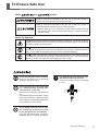
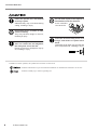
Automatic Tool Changer
ZAT-650
User's Manual
Thank you very much for purchasing the product.
• To ensure correct and safe usage with a full understanding of this product's performance, please be sure to read through
this manual completely and store it in a safe location.
• Unauthorized copying or transferral, in whole or in part, of this manual is prohibited.
• The contents of this operation manual and the specifications of this product are subject to change without notice.
• The operation manual and the product have been prepared and tested as much as possible. If you find any misprint or
error, please inform us.
• Roland DG Corp. assumes no responsibility for any direct or indirect loss or damage which may occur through use of
this product, regardless of any failure to perform on the part of this product.
• Roland DG Corp. assumes no responsibility for any direct or indirect loss or damage which may occur with respect to
any article made using this product.
Table of Contents
To Ensure Safe Use ......................................................................................................... 3
Chapter 1 System Structure........................................................................................... 5
1-1 Features of the ZAT-650 ................................................................................................................ 6
1-2 Possible System Configurations Using the ZAT-650 ..................................................................... 6
Installable Combinations .......................................................................................................................................................................... 6
Programs Compatible with ATC ............................................................................................................................................................... 6
Chapter 2 Implementing the ATC Unit ........................................................................... 7
2-1
2-2
2-3
2-4
List of Included Items ..................................................................................................................... 8
Conditions for Compressed Air ...................................................................................................... 9
Usable Tool Holders ..................................................................................................................... 10
Installing the ATC Unit .................................................................................................................. 11
Step 1: Install the Spindle and the Cylinder ........................................................................................................................................... 11
Step 2: Install the Control Box ............................................................................................................................................................... 13
Step 3: Install the Tool Magazine ........................................................................................................................................................... 16
Step 4: Make Settings and Adjust ........................................................................................................................................................... 18
Chapter 3 Basic Operation (Common for RML-1 and NC Codes) ............................ 19
3-1 Important Notes on Switching the Power On and Off .................................................................. 20
Before You Switch Off the Power .......................................................................................................................................................... 20
Important Notes When Switching On the Power ................................................................................................................................... 20
3-2 Usage and Handling of the Tool Magazine .................................................................................. 21
Points to Observe When Loading Tools ................................................................................................................................................. 21
Loading a Tool ......................................................................................................................................................................................... 21
3-3 Selecting Tools Through Key Operations ..................................................................................... 22
Chapter 4 Operation in the RML-1 Mode .................................................................... 23
4-1 What Is the Tool-length Offset? .................................................................................................... 24
4-2 Measurement of Tool Length and Starting Cutting ...................................................................... 25
Step 1: Measure the Tool Lengths .......................................................................................................................................................... 25
Step 2: Set Z0 (the Z-axis Origin Point) ................................................................................................................................................ 26
Chapter 5 Operation in the NC Code Mode ................................................................ 27
5-1 Tool Selection and Tool-length Offset .......................................................................................... 28
Tool Selection .......................................................................................................................................................................................... 28
Tool-length Offset ................................................................................................................................................................................... 28
Offset Amounts for Tool Selections Made Using Key Operations ........................................................................................................ 28
5-2 Preparations for Tool-length Offset .............................................................................................. 29
Step 1: Perform Automatic Measurement of Tool Length ..................................................................................................................... 29
Step 2: Make the Settings for the Workpiece Coordinate System ......................................................................................................... 31
Step 3: Make the Preparations in the Program ....................................................................................................................................... 31
5-3 Tool-length Adjustment and Manual Setting ................................................................................ 32
Tool-length Adjustment ........................................................................................................................................................................... 32
Setting the Offset Value Manually .......................................................................................................................................................... 32
Chapter 6 NC Code Reference ..................................................................................... 33
G43, G49 Tool-length Offset ............................................................................................................. 34
M06 Tool Selection ........................................................................................................................... 35
Table of Contents
1
Table of Contents
Chapter 7 Menu Reference ........................................................................................... 37
7-1
7-2
7-3
7-4
RML-1 Menu Flowchart ................................................................................................................ 38
NC Code Menu Flowchart ............................................................................................................ 40
Descriptions of RML-1 Menu Items .............................................................................................. 42
Descriptions of NC Code Menu Items .......................................................................................... 44
Chapter 8 Other Information ........................................................................................ 47
8-1 Daily Maintenance ........................................................................................................................ 48
Cleaning and Lubrication ........................................................................................................................................................................ 48
Maintenance for the Air Regulator ......................................................................................................................................................... 48
Inspection of the Spindle Unit ................................................................................................................................................................ 48
8-2
8-3
8-4
8-5
8-6
Corrective Action for Error Messages .......................................................................................... 49
X-, Y- and Z-axis Travels .............................................................................................................. 51
Tool-magazine Expansion ............................................................................................................ 52
Extended RML-1 Commands ....................................................................................................... 52
Specifications ............................................................................................................................... 53
Other company names and product names are trademarks or registered trademarks of their respective holders.
Copyright© 2002 Roland DG Corporation
2
Table of Contents
http://www.rolanddg.com/
To Ensure Safe Use
About
and
Notices
Used for instructions intended to alert the user to the risk of death or
severe injury should the unit be used improperly.
Used for instructions intended to alert the user to the risk of injury or
material damage should the unit be used improperly.
* Material damage refers to damage or other adverse effects caused
with respect to the home and all its furnishings, as well to domestic
animals or pets.
About the Symbols
The symbol alerts the user to important instructions or warnings. The specific meaning
of the symbol is determined by the design contained within the triangle. The symbol at
left means "danger of electrocution."
The
symbol alerts the user to items that must never be carried out (are forbidden).
The specific thing that must not be done is indicated by the design contained within the
circle. The symbol at left means the unit must never be disassembled.
The
symbol alerts the user to things that must be carried out. The specific thing that
must be done is indicated by the design contained within the circle. The symbol at left
means the power-cord plug must be unplugged from the outlet.
Do not disassemble, repair, or modify.
Doing so may lead to fire or abnormal
operation resulting in injury.
Let compressed air out of the air regulator before removing the bowl.
The bowl or the like may fly off, resulting
in injury.
Do not use while in an abnormal state
(i.e., emitting smoke, burning odor,
unusual noise, or the like).
Doing so may result in fire or electrocution.
Immediately switch off the power, unplug
the power cord from the electrical outlet,
and contact your authorized Roland DG
Corp. dealer or service center.
Do not apply solvents such as thinner, cutting oils or direct rays of the
sun to the bowl of the air regulator.
They may degrade the bowl, resulting in
breakage when air pressure is applied.
To Ensure Safe Use
3
To Ensure Safe Use
Fasten the spindle, tool, and material
securely in place.
Otherwise they may come loose during
cutting, resulting in injury.
Do not allow liquids, metal objects or
flammables inside the machine.
Such materials
can cause fire.
Do not wear gloves, a necktie or widesleeved clothing.
They may become caught in the tool,
resulting in injury.
Set the cutting area so that the tool
does not contact the tool magazine,
the rotary axis unit or the like.
Pieces of the tool or workpiece may fly
off, resulting in injury.
Insert the air hose firmly as far as it
will go, and secure it in place with a
band.
Otherwise the air hose may fly loose and
blow compressed air, resulting in injury.
In addition to these symbols, the symbols shown below are also used.
: Indicates information to prevent machine breakdown or malfunction and ensure correct use.
: Indicates a handy tip or advice regarding use.
4
To Ensure Safe Use
Chapter 1
System Structure
This chapter describes the possible configurations using this unit.
5
1-1 Features of the ZAT-650
The ZAT-650 is a automatic tool changer unit (ATC unit) that adds automatic tool-changing functions to the MODELA
Pro. It makes it easy to perform cutting operations while using a number of tools of different types. The tool-length
offset feature and the automatic measurement feature for tool length make it nearly unnecessary to modify programs
even when using tools of different lengths. You can also combine the unit with the rotary axis unit, making it possible to
perform multiple-surface cutting with automatic tool changes.
The ZAT-650 requires a separate device to supply compressed air, such as a compressor.
1-2 Possible System Configurations Using the ZAT-650
Installable Combinations
The ZAT-650 can be combined with the following products.
MODELA Pro series
Rotary axis units
MDX-650A
Yes
MDX-650
No
MDX-500
No
ZCL-650A
Yes
ZCL-650
No
* Use with the dedicated spindle packed with the ATC unit. The ZS-650T, ZS-500SH, and the like cannot be used.
* When the ZAT-650 is installed, the following optional equipment cannot be used: Vacuum adapters for chip cleaning (ZAD500T, ZAD-500S, etc.), table spacers (ZA-500 series, etc.), or a vacuum table (ZV-500A).
Programs Compatible with ATC
To perform automatic tool changes, you need to use a program that supports ATC, or to implement NC programming.
Even with a program that does not support ATC, it's possible to perform cutting using a single tool, but continuous
cutting with automatic tool changes is not possible. Check the compatibility of the program before you use it.
6
Chapter 1 System Structure
Chapter 2
Implementing the ATC
Unit
This chapter describes what you need to implement the ATC unit and
how to install it.
7
2-1 List of Included Items
Items
Number of pieces
ATC spindle unit
1
Air cylinder
1
Tool magazine
1
Control box
1
Air regulator
1
Z0 sensor base
1
Air hose
1
Air nozzle
1
Positioner
1
Cap screws
M4 x 8 mm
M4 x 15 mm
M4 x 25 mm
M4 x 35 mm
M6 x 12 mm
3
4
4
2
6
Screws (with a knob)
2
Square nuts
4
Washers
4
Wrenches
Hexagonal screw driver (for M4 cap screws)
L-shaped hexagonal wrench (for M6 cap screws)
1
1
Retaining bands (black)
6
Retaining band (white)
1
* A compressed-air supply must be procured separately. See "2-2 Conditions for Compressed Air" for the requirements.
* A tool holder must be procured separately. See "2-3 Usable Tool Holders" for the requirements.
8
Chapter 2 Implementing the ATC Unit
2-2 Conditions for Compressed Air
The ATC unit requires compressed air. Provide a compressor or other compressed-air supply that meets the following
conditions.
• Air pressure 0.7 to 1 MPa
• Air volume 50 L/min. or more (at 0.7 to 1 MPa air pressure)
The piping from the ATC unit is as shown below. Provide suitable air hoses, joints, and the like.
• Hose outer diameter 10 mm (polyurethane tubing)
10 mm
Do not supply compressed air to the regulator at higher than 1 MPa. Doing so may damage the regulator.
Chapter 2 Implementing the ATC Unit
9
2-3 Usable Tool Holders
Use tools that meet the following conditions.
Required Tool Dimensions
Taper shank
(JBS4002 15T, 7/24 taper)
Dia. 24 mm or less
Dia.45 mm or less
Pull stud
(JBS4002 15P [45˚], special)
Dia. 10 mm or less
18 mm or more (when gripped)
110 mm or less
Dimension Drawing of the Taper-shank Area
R0
.
C0 5 ma
.5 x
13.5
27
21
19.050
M6
6.5
7.5
60˚
10
6.5
M6
4
60˚
7
R0
.5
7/24 taper
.5
C1
R0
45˚
Gauge surface
5
17
15 min
0
1.5 -0.4
28
21 min
27
1.5 ±0.4
2.5
5
11
Unit: mm
10
Chapter 2 Implementing the ATC Unit
2-4 Installing the ATC Unit
The installation methods are partly different depending on whether the unit is to be used in combination with a rotary
axis unit. When you are using the units in combination, finish installing the rotary axis unit before you install the ATC
unit.
Step 1: Install the Spindle and the Cylinder
Procedure
1
In the following operation, you move the spindle head to the left.
(1) Close the spindle cover on the main unit.
(2) Switch on the power to the machine, then press the [ENTER] key. The spindle head moves to the left.
2
Switch off the power and unplug the power cord.
Be sure to switch off the power before you attempt installation.
Otherwise unintended operation of the machine may result in injury.
3
Install the air nozzle on the spindle unit.
Tighten using a wrench (14 mm).
Spindle unit
Air nozzle
4
Align the pin on the back of the spindle unit
with the pin-hole on the slider, and support it
with your hand.
5
Insert the cap screw (M4 x 25 mm) at the location shown in the figure, then tighten using the
hexagonal screwdriver.
Chapter 2 Implementing the ATC Unit
11
2-4 Installing the ATC Unit
6
Pass the belt through under the motor pulley
and engage on the spindle pulley.
Spindle belt
Spindle pulley
* Note that the spindle belt is packed with the main unit.
Motor pulley
7
While pressing down on the belt engaged on
the spindle pulley, turn the motor pulley in the
direction of the arrow to attach the belt.
8
Turn the motor pulley several times so as to
position the belt on the motor pulley and spindle
pulley as shown in the figure.
9
Install the air cylinder.
Air cylinder
Position the notch flush against the slider and secure in
place with the four cap screws (M4 x 15 mm).
Slider
Notch
Slider
Next, go on to "Step 2: Install the Control Box."
12
Chapter 2 Implementing the ATC Unit
2-4 Installing the ATC Unit
Step 2: Install the Control Box
Procedure
1
Make sure that the power to the main unit is
switched off and its power cord is unplugged.
2
If you're using the optional safety cover, remove
the back panel.
3
Install the air regulator and air hoses on the control box.
Control box
Air regulator
M4 x 8 mm
cap screw
M4 x 8 mm
cap screw
After connecting the hose,
secure it in place using a
retainer.
To the compressed-air
supply
Air hose
To connect:
Insert all the way into the
joint.
4
To detach:
Pull out while pressing in the
ring.
After connecting the hose,
secure it in place using a
retaining band.
Mount the control box on the main unit.
It is held in place by magnets. The mounting location is different when you're using the optionally available safety cover.
Without the safety cover
Mount it on the back of the machine.
With the safety cover
Mount it on the left side of the cover and pull the cables inside.
Chapter 2 Implementing the ATC Unit
13
2-4 Installing the ATC Unit
5
Connect the hoses and cables.
Screws
Large
connector
Small
Small
connector hose
(1) Connect the large connector to the back of the machine.
Large
hose
(3) Detach the rubber cap, and press the white retaining band
into the hole to attach.
White retaining
band
(2) Pull in the small connector and the small hose through
the hole in the top of the spindle, and connect to the air
cylinder.
(4) Connect the large hose to the air nozzle and secure with
the white retaining band.
The joint rotates freely.
14
Chapter 2 Implementing the ATC Unit
2-4 Installing the ATC Unit
6
Bundle the hoses and cables together and secure with the black retaining bands.
Ensure enough slack that the hoses and cables do not catch or snag when the spindle head moves from side to side.
Next, go on to "Step 3: Install the Tool Magazine."
Chapter 2 Implementing the ATC Unit
15
2-4 Installing the ATC Unit
Step 3: Install the Tool Magazine
The mounting location of the tool magazine differs depending on whether you're using the ATC unit in combination
with a rotary axis unit.
Procedure
1
In the following operation, you move the spindle to the magazine-adjustment location.
(1) Close the spindle cover on the main unit.
(2) Switch on the power to the main unit, then press the [ENTER] key. After
initialization, the coordinate-view screen appears.
(3) Press the [ENTER] key to display the main menu. Use the dial to select
[ATC], then press the [ENTER] key.
Use the dial to select [MAGAZINE SETUP], then press the [ENTER] key.
(4) Use the dial to select [MAGAZINE POS.1], then press the [ENTER] key.
2
*X
Z
0 Y
0
0 5000 RPM
13> 6 MAGAZINE SETUP
7 NO. OF STOCKS
13-6> 1 MAGAZINE POS.1
2 VIEW POSITION
(5) Make sure there are no obstructions, then press the [ENTER] key again. The
spindle moves to the magazine-adjustment location.
TAKE OFF TOOLS FROM
STOCKS,THEN ENTER
Open the spindle cover and make sure that the screen shown at
right is displayed.
CAUTION!
SP
COVER OPEN
Be sure to carry out installation with the spindle cover open.
Performing the operation with the cover closed may result in injury due to unintended operation
of the machine.
3
Loosely secure the tool magazine.
When Using with No Rotary Axis Unit
(1) Assemble a cap screw (M6 x 12 mm), washer, and
square nut onto each of the four corners of the tool
magazine. Tighten the cap screws loosely.
(2) Slide the tool magazine to pass the square nuts into
the T slots, and loosely tighten at the location on the
table shown in the figure. Orient the magazine so that
the openings face toward the left.
Tool magazine
Cap screw
Table
Washer
T slot
Washer
Square nut
Square nut
T slot
16
Chapter 2 Implementing the ATC Unit
2-4 Installing the ATC Unit
Cap screw
When Using in Combination with a Rotary Axis Unit
Washer
Place on the base of the rotary axis unit and loosely tighten
using two cap screws (M6 x 12 mm) and washers. Orient
the magazine so that the openings face toward the front.
4
Install the positioner on the spindle unit.
Orient it as shown in the figure and secure it in place
with two screws (with a knob).
Positioner
Screw with a knob
5
Position the tool magazine flush against the positioner, then tighten the cap screws completely.
Perform positioning with the tool magazine standing straight up. Using excessive force to position the tool magazine flush
against the positioner may cause the tool magazine to tilt, making correct positioning impossible.
When Using with No Rotary Axis Unit
6
When Using in Combination with a Rotary Axis Unit
Switch off the main unit and remove the positioner.
After tightening the cap screws in step 5, be sure to switch off the power.
Z0 sensor base
7
When you are using the ATC unit with no rotary
axis unit, mount the Z0 sensor base on the
magazine.
Secure it in place using two cap screws (M4 x 35 mm).
This is not necessary when you're using the ATC unit in
combination with a rotary axis unit.
Next, go on to "Step 4: Make Settings and Adjust."
Chapter 2 Implementing the ATC Unit
17
2-4 Installing the ATC Unit
Step 4: Make Settings and Adjust
Procedure
1
Supply compressed air to the ATC unit. Pull up the knob on
the air regulator, then adjust so that the meter reads 0.5 to
0.65 MPa. After adjusting, press in the knob to return it to its
original position.
Do not adjust the regulator at higher than 0.7 MPa. Doing so may damage the ATC unit.
2
Adjust the orientation of the air nozzle to blow away any buildup of cutting waste from the stock area
on the top surface of the magazine. Adjust the air nozzle as required so that it does not strike the tool,
workpiece or other areas during operation.
Bottom surface of
the spindle
45 mm (2 in.)
25 mm (1in.)
Orient the nozzle tip toward the center
of the spindle.
3
18
Align the nozzle tip with the height of
the bottom surface of the spindle, then
angle it downward.
In the following operation, set the spindle type to [HIGH
TORQUE].
(1) Close the spindle cover and switch on the power to the main unit.
Press the [ENTER] key. After initialization, the coordinate-view screen appears.
*X
Z
(2) Press the [ENTER] key to display the main menu. Use the dial to select
[OTHERS], then press the [ENTER] key.
Use the dial to select [SPINDLE UNIT], then press the [ENTER] key.
10> 2 SPINDLE UNIT
3 BUZZER
(3) Use the dial to select [HIGH TORQUE], then press the [ENTER] key.
10-2 SPINDLE UNIT
<HIGH TORQUE>
Chapter 2 Implementing the ATC Unit
0 Y
0
0 5000 RPM
Chapter 3
Basic Operation
(Common for RML-1 and NC Codes)
This chapter describes the most basic operations that you should know
before you try to use the unit. Be sure to read it before you start work.
19
3-1 Important Notes on Switching the Power On and Off
Before You Switch Off the Power
Return the tool (tool holder) to the magazine before you switch off the power. As a rule, you should never power down
while the spindle is gripping a tool.
Important Notes When Switching On the Power
When the power is switched on while the spindle is gripping a tool, a forced release of the tool is performed. Inadvertent
operation while in this state may result in the tool being dropped, so be sure to give attention to this point. Pressing the
[ENTER] key after switching on the power performs a forced release immediately without a return to the magazine.
Carry out this operation while securely supporting the tool by hand to keep it from being dropped.
20
Chapter 3 Basic Operation
3-2 Usage and Handling of the Tool Magazine
Points to Observe When Loading Tools
Always make sure the machine is in the following state before performing tasks such as loading or changing a tool (tool
holder). Performing such tasks incorrectly may result in injury or malfunction.
• The spindle must not be gripping a tool.
• Cutting operations must have ended and operation stopped.
Loading a Tool
Loading Location
Load the tool holder at the location on the magazine shown in the figure. You may load it in any stock, or load more than
one. When loading, carefully clean away any buildup of cutting waste on the tool holder and magazine.
Stopper Adjustment
Adjust the height of the stoppers to match the loaded tools. Lower it if it strikes the tool holder, and raise it if it does not
reach the tool.
Also, the stopper has two notches, one large and one small. If the diameter of the end mill is 5 mm or less, reinstall the
stopper, orienting it to use the small notch.
Tool holder
Stock
Stopper
Tool magazine
Stopper direction
Large notch
Small notch
Chapter 3 Basic Operation
21
3-3 Selecting Tools Through Key Operations
When you want to select a tool using key operations, follow the steps below. The operation differs slightly depending on
whether you are using the RML-1 or the NC code command set.
Procedure
1
Display the main menu. Use the dial to select [ATC], then
press the [ENTER] key.
>13 ATC
14 To Coordinate
2
Use the dial to choose [TOOL SELECT], then press the [ENTER] key.
13> 1 TOOL SELECT
2 OFFSET NUMBER
3
Use the dial to select the number of the tool you want to
grasp, then press the [ENTER] key. If you are in the NC code
mode, then press the [ENTER] key a second time.
13-1> 1 TOOL1
2 TOOL2
The unit moves to retrieve the tool from the stock number you selected. If
a tool is already gripped, then it is changed. Also, compressed air is blown
from the air nozzle and the chucking portion at this time to clean away
cuttings.
Stock
No.1
No.2
No.3
No.4
If you are in the NC code mode, then tool-length offset is not
enabled in this operation, and only the tool-selection operation
is performed.
☞ See "5-1 Tool Selection and Tool-length Offset."
4
Use the dial to select [RETURN], then press the [ENTER]
key.
13-1> 5 RETURN
6 RELEASE
The gripped tool is returned to the magazine.
Important Note When [RELEASE] Is Selected
If [RELEASE] is selected in step 3 or 4 above, a forced release of the tool is performed immediately without returning the tool
to the magazine. Inadvertent operation while in this state may result in the tool being dropped, so be sure to give attention to
this point.
This operation is employed when it is necessary to detach a tool manually for some reason. Carry out this operation while
securely supporting the tool by hand to keep it from being dropped.
22
Chapter 3 Basic Operation
Chapter 4
Operation in the RML-1
Mode
This chapter explains basic operations when the RML-1 command set
is selected.
23
4-1 What Is the Tool-length Offset?
When a tool is changed and the tool length changes, the cutting position along the Z axis also changes. When the tool is
changed, it is necessary to perform some operation that takes the tool length into consideration, such as, for example,
resetting Z0 (the Z-axis origin point). The tool-length offset is a function that automatically adjusts the Z-axis position
while taking the tool length into account. In short, it is sufficient to set Z0 only once, at the start. Then after the tool is
changed, adjustment to keep the Z0 position the same is performed automatically.
◆ Before tool-length offset
◆ After tool-length offset
Spindle unit
Reference position
Offset
value A
Tool length A
Offset
value B
Offset
value C
Aligned with the reference
position after correction
Tool length B
Tool length C
To enable this, it is necessary to measure the length of each tool and register (save) these measurements in the machine
ahead of time. There are two registration methods: one where the tool lengths are measured automatically, and one
where you measure the tool lengths and register the values yourself.
In the RML-1 mode, tool-length offset is always performed according to the registered tool lengths. Tool-length offset
is carried out when a tool-select operation is performed, regardless of whether it is performed by an instruction from the
computer or by key operation.
24
Chapter 4 Operation in the RML-1 Mode
4-2 Measurement of Tool Length and Starting Cutting
This section describes the preparations up to starting cutting using a program that supports automatic tool changes.
When the preparations are complete, you simply use the program to specify the tool numbers you want to use for
cutting. There is no need to perform operations such as resetting Z0 after every tool change.
Step 1: Measure the Tool Lengths
This section explains how to measure tool length automatically. The procedures are slight different depending on whether
you are using the unit in combination with a rotary axis unit.
Procedure
1
2
Load the magazine with the tools you want to use for cutting.
When using with no rotary axis unit:
When using in combination with a rotary axis unit:
Connect the Z0 sensor (included with the main unit), and
then place the Z0 sensor on the sensor base.
Detach the sensor cover on the rotary axis unit.
Z0 sensor
3
Display the main menu. Use the dial to select [ATC], then
press the [ENTER] key.
4
Use the dial to select [LENGTH SCAN], then press the [ENTER] key.
>13 ATC
14 To Coordinate
13> 3 LENGTH SCAN
4 TOOL LENGTH
The machine sequentially grasps each tool, starting with stock No. 1, and
brings it into contact with the sensor.
If the sensor and the tool are far apart and making contact takes a long time, then hold down the [-Z] key.
This makes the lowering speed faster. Release the [-Z]
key before contact is made with the sensor.
5
If contact occurs while the [-Z] key is depressed, correct measurement is impossible. Be sure to release the
key before contact is made.
When all the tools have been measured and operation stops, the procedure has ended. Remove the
Z0 sensor. Alternatively, attach the sensor cover.
After measuring the tool lengths, do not improperly replace a tool with a different one or change the sequence or the tools.
Doing so destroys the correspondence between the actual tool lengths and the offset values, and may result in cutting-in at
unexpected depths.
Chapter 4 Operation in the RML-1 Mode
25
4-2 Measurement of Tool Length and Starting Cutting
Step 2: Set Z0 (the Z-axis Origin Point)
After you finish measuring the tool lengths, you make the setting for Z0.
Procedure
1
Operate the keys to grasp any tool.
2
Make the Z0 setting with the grasped tool.
3
Return the grasped tool to the magazine.
You may choose any tool whose tool length has been measured.
Make the setting with any tool that has been measured. You do not need to set this individually for every tool to be used in
cutting.
This completes the preparations. When you send cutting data from a program, the tool specified by the program is
automatically grasped, and cutting starts. Because tool-length offset is applied, the position of the tool tip remains
uniform when one tool is changed for another.
26
Chapter 4 Operation in the RML-1 Mode
Chapter 5
Operation in the NC
Code Mode
This chapter explains basic operations when the NC command set is
selected, and the basics of NC code programming.
27
5-1 Tool Selection and Tool-length Offset
Tool Selection
To grasp a desired tool or return it to the magazine, you use M06. This code only selects a tool. Tool-length offset is not
enabled.
Tool-length Offset
This function is used to correct for discrepancies between the tool length anticipated by a program and the actual tool
length. Using this eliminates the need for the program to take changes in tool length into account when a tool change is
performed, and makes it unnecessary to redo the setting for the workpiece origin every time the tool is changed. To start
and cancel tool-length offset, you use G43 and G49.
◆ Before tool-length offset
◆ After tool-length offset
Spindle unit
Reference position
Offset
value A
Offset
Offset
value B value C
Aligned with the reference
position after correction.
Tool length B
Tool length A
Tool length C
To perform tool-length offset, you must register (save) the offset amount in the machine. You can register offset amounts
from No.1 up through No. 16. There are two registration methods: one where the tool lengths are measured automatically, and one where you set the offset amounts manually.
Tool selections by M06 are not coordinated with offsets No. 1 through No. 16 in any way. The program must specify the
number of the offset amount to assign to a selected tool (G43). This involves presetting the tool-length offsets corresponding to 16 tools in the machine.
Offset Amounts for Tool Selections Made Using Key Operations
You can enable tool-length offset even when you select tools manually using
the procedures in "3-3 Selecting Tools Through Key Operations." At the [TOOL
SELECT] menu, specifying a tool number and pressing the [ENTER] key displays a screen for selecting an offset number. Selecting an offset number here
achieves the same result as performing tool-length offset using G43. The display shows the coordinate values after tool-length offset.
Selecting offset No. 0 at this screen causes no tool-length offset to be applied
here.
28
Chapter 5 Operation in the NC Code Mode
SELECT AND ENTER
TOOL OFFSET No. < 1 >
Offset number
5-2 Preparations for Tool-length Offset
This section describes the preparations up to performing cutting using tool-length offset. There are tasks that you perform on the machine, and specifications you make in the programming.
Step 1: Perform Automatic Measurement of Tool Length
This section explains the basic operations of how to perform automatic measurement of tool length. The procedures are
slight different depending on whether you are using the unit in combination with a rotary axis unit.
Procedure
1
Load the tools you want to measure into the
magazine.
Stock No.1 No.2 No.3 No.4
In this example, the tools are A through D.
Tool
A
2
B
C
D
When using with no rotary axis unit:
When using in combination with a rotary axis unit:
Connect the Z0 sensor (included with the main unit), and
then place the Z0 sensor on the sensor base.
Detach the sensor cover on the rotary axis unit.
Z0 sensor
3
Display the main menu. Use the dial to select [ATC], then
press the [ENTER] key.
>13 ATC
14 To Coordinate
4
Use the dial to select [LENGTH SCAN], then press the [ENTER] key.
13> 2 LENGTH SCAN
3 TOOL LENGTH
(Continued to on next page.)
Chapter 5 Operation in the NC Code Mode
29
5-2 Preparations for Tool-length Offset
5
Specify the tool length to register as a particular offset-amount
number.
Use the dial to select the offset number. Pressing the [ENTER] key inputs
it and moves the cursor to the next one. Repeat this procedure to make the
settings for all the stocks.
In this example, tools A through D are registered as offsets No. 1 through
No. 4.
STOCK No. 1
OFFSET No. 1
Stock
2 3 4
2 3 4
No.1 No.2 No.3 No.4
Offset No.1 No.2 No.3 No.4
If you select offset No. 0 for a stock, that stock is not measured.
You can skip measurement of stocks where no tool is loaded.
Tool
A
6
When you have made the settings for all stocks and the
screen shown at right appears, press the [ENTER] key.
B
C
D
TOOL LENGTH SCAN
"ENTER" TO START
The machine sequentially grasps each tool, starting with stock No. 1, and
brings it into contact with the sensor.
If the sensor and the tool are far apart and making contact takes a long time, then hold down the [-Z] key.
This makes the lowering speed faster. Release the [-Z]
key before contact is made with the sensor.
7
If contact occurs while the [-Z] key is depressed, correct measurement is impossible. Be sure to release the
key before contact is made.
When all the tools have been measured and operation stops, the procedure has ended. Remove the
Z0 sensor. Alternatively, attach the sensor cover.
If necessary, replace the tools in the magazine with other tools and repeat steps 4 through 6. You can register a total of 16
offset amounts.
30
Chapter 5 Operation in the NC Code Mode
5-2 Preparations for Tool-length Offset
Step 2: Make the Settings for the Workpiece Coordinate System
Load the magazine with tools that have already been measured and set the workpiece origin point (the cutting-start
location).
Procedure
1
Load the magazine with tools whose offset amounts have
been registered.
Offset No.1 No.2 No.3 No.4
In this example, tools A through D that you measured in Step 1 are loaded.
Tool
A
2
Perform key operations to grasp any tool, then select the
corresponding offset number.
B
C
D
SELECT AND ENTER
TOOL OFFSET No. < 1 >
In this example, tool A is grasped. The tool length of tool A is registered
as offset No. 1, so here you select offset No. 1.
3
Move the tool to the cutting-start location that the program
expects, then set the workpiece origin point.
There are a wide variety of ways to get the workpiece origin, depending on the program, but one example
follows.
(1) Move the tool to the lower left area of the workpiece.
(2) Lower the tool and align the tool tip with the surface of the workpiece.
(3) Use G54, EXOFS, or the like to set the workpiece origin (the origin point for the X and Y axes and for
the Z axis) at this location.
4
Return the grasped tool to the magazine.
Step 3: Make the Preparations in the Program
In the program, specify the tool number you want to select (M06). Also specify the offset number corresponding to the
tool in the program (G43). For example, if you want to use tool A for rough cutting and tool B for finishing, specify
offset No. 1 for the rough cutting and offset No. 2 for the finishing.
This completes the preparations. When you send the program to the machine, the specified tool is automatically grasped
and cutting starts. The tool-length offsets of the specified offset numbers are applied, and so even when one tool is
changed for another the position of the tip remains uniform.
Chapter 5 Operation in the NC Code Mode
31
5-3 Tool-length Adjustment and Manual Setting
Tool-length Adjustment
You can adjust the results of the automatic measurement you carried out earlier in "Step 1: Perform Automatic Measurement of Tool Length."
Procedure
1
Display the main menu. Use the dial to select [ATC], then
press the [ENTER] key.
>13 ATC
14 To Coordinate
2
Use the dial to select [TOOL LENGTH], then press the [ENTER] key.
13> 3 TOOL LENGTH
4 AIR PRESS.
3
Turn the dial to select the offset number you want to adjust.
Press the [ENTER] key.
13-3> 1 OFFSET NO.1
2 OFFSET NO.2
4
Use the dial to adjust the value, then press the [ENTER] key.
13-3> 1 OFFSET NO.1
< 0.00mm>
When the actual tool length is longer than the registered value, cutting-in
is deeper than intended. In such cases you increase the value. Conversely,
when cutting-in is too shallow, you reduce the value.
Setting the Offset Value Manually
You can enter tool lengths (offset amounts) you measured yourself by using a procedure similar to the one in the
preceding "Tool-length Adjustment."
Measure the length to the tool end, referenced from a particular location on the tool holder. You may use any location on
the tool holder as the reference, but it must be consistent for all tools. In this way, you register the measured lengths as
offset amounts.
You can also get the same results by deciding on any one tool as a reference tool, and entering the differences from this
tool. For instance, if there is a tool that is 15 mm shorter than the reference tool, you make the corresponding offset
amount -15 mm. Also, you make the offset amount for the reference tool itself 0 (no tool-length offset). The reference
position in this case is the tip of the reference tool.
Reference tool
Reference position
32
Offset amounts
Chapter 5 Operation in the NC Code Mode
Chapter 6
NC Code Reference
This chapter describes in detail the extended NC codes that become
available through the addition of the ATC unit.
33
G43, G49
Tool-length Offset
Format
G43 H number
G49
Parameter
Function
No-error range
Effective range
number
Offset number
0 through 16
0 through 16
Description
This moves the Z axis by the specified offset amount. It is used to correct for a change in tool length due to a tool change,
to keep the position of the tip uniform, and so on.
G43 starts tool-length offset. You set the offset amount (offset No. 1 through No. 16) in the machine ahead of time, and
specify the offset number with number. G49 cancels tool-length offset. Specifying 0 (zero) for number with G43 similarly cancels tool-length offset.
If an axis-movement command is present within the same block as a G43 command, the end point for axis movement is
the Z-axis coordinate for the movement destination plus the offset. When no axis-movement command is present, the
command is taken to be for a movement distance of zero, and movement along the Z axis by only an amount equal to the
offset is performed. This is the same for both absolute and incremental coordinates.
G43 and G49 are commands in the same group. These commands remain in effect even outside the block until a new
G43 or G49 command is received.
The offset amount for offset No. 0 is always 0 (zero). You cannot register any value for offset No. 0.
Registering an Offset Amount
Registration of offset No. 1 through No. 16 is performed by key operations on the machine. Specification by a program
is not possible. For more information, see chapter 5.
Sample Program
%
O0001
G90
G49 M06 T2
G00 X1000 Y1000
G43 H1 Z-1000
F10 S5000 M03
G01 X2000 Y2000
M05
G49 M06 T0
M30
%
34
Data start
Program number
Specify absolute coordinates
Get tool in stock No. 2
Positioning
Start tool-length offset with offset No. 1 and move to corrected position
Rotate spindle
Linear-interpolation movement
Stop spindle
Cancel tool-length offset and return tool
Program end
Data end
Chapter 6 NC Code Reference
M06
Tool Selection
Format
M06 T number
Parameter
Function
No-error range
Effective range
number
Stock number
0 through 4 or
0 through 8 *
0 through 4 or
0 through 8 *
*
When expansion magazine is installed
Description
This gets, changes, or returns a tool loaded in the magazine. You specify the stock number where the tool you want to get
or change is loaded with number. Specifying 0 (zero) returns the tool.
Here, number signifies a stock number in the magazine. It does not directly specify the tool itself. Also, M06 has no
tool-length offset function.
Do not specify more than one M06 or T code in the same block. Also, specifying M06 alone or a T code alone results in
an error. Specify M06 and a T code together, as a pair.
Any command to get or change a tool that is already grasped is ignored.
Chapter 6 NC Code Reference
35
36
Chapter 7
Menu Reference
This chapter describes in detail the extended menus codes that become available through the addition of the ATC unit.
37
7-1 RML-1 Menu Flowchart
Main menu
>13 ATC
13-1 TOOL SELECT
13>1 TOOL SELECT
2 OFFSET NUMBER
13-1> 1 TOOL 1
2 TOOL 2
3 LENGTH SCAN
4 TOOL LENGTH
5 AIR PRESS.
6 MAGAZINE SETUP
7 NO. OF STOCKS
8 To Main Menu
3 TOOL 3
4 TOOL 4
5 RETURN
6 RELEASE
7 To Main Menu
-<END>13-2 OFFSET NUMBER
13-2> 1 STOCK 1->(1)
2 STOCK 2->(2)
3 STOCK 3->(3)
4 STOCK 4->(4)
5 To ATC Menu
-<END>-
13-2> 1 STOCK 1
OFFSET NUMBER <1>
13-2> 2 STOCK 2
OFFSET NUMBER <2>
13-2>3 STOCK 3
OFFSET NUMBER <3>
13-2> 4 STOCK 4
OFFSET NUMBER <4>
13-3 LENGTH SCAN
NOW SCANNING
TOOL LENGTH...
13-4 TOOL LENGTH
13-4> 1 OFFSET NO.1
2 OFFSET NO.2
13-4> 1 OFFSET NO.1
< 0.00mm>
3 OFFSET NO.3
13-4> 2 OFFSET NO.2
< 0.00mm>
16 OFFSET NO.16
17 To ATC Menu
-<END>-
Next page
38
Chapter 7 Menu Reference
13-4>16 OFFSET NO.16
< 0.00mm>
7-1 RML-1 Menu Flowchart
Previous page
13-5 AIR PRESS.
13>5 AIR PRESS.
<0.50 MPa>
13-6 MAGAZINE SETUP
13-6>1 MAGAZINE POS.1
2 MAGAZINE POS.2
TAKE OFF TOOLS FROM
STOCKS,THEN "ENTER"
3 VIEW POSITION
4 To ATC Menu
-<END>13-7 NO. OF STOCKS
13>7 NO. OF STOCKS
<4>
ARE YOU SURE?
DECIDED BY "ENTER"
Pause menu
PAUSE > AIR PRESS.
PAUSE: AIR PRESS.
<0.50 MPa>
Chapter 7 Menu Reference
39
7-2 NC Code Menu Flowchart
Main menu
>13 ATC
13-1 TOOL SELECT
13>1 TOOL SELECT
2 LENGTH SCAN
13-1> 1 TOOL 1
2 TOOL 2
3 TOOL LENGTH
4 AIR PRESS.
5 MAGAZINE SETUP
6 NO. OF STOCKS
7 To Main Menu
SELECT AND ENTER
TOOL OFFSET No. <0>
3 TOOL 3
4 TOOL 4
5 RETURN
6 RELEASE
7 To Main Menu
-<END>-
13-2 LENGTH SCAN
STOCK No. 1 2 3 4
OFFSET No. 0 0 0 0
TOOL LENGTH SCAN
"ENTER" TO START
13-3 TOOL LENGTH
13-3> 1 OFFSET NO.1
2 OFFSET NO.2
13-3> 1 OFFSET NO.1
< 0.00mm>
3 OFFSET NO.3
13-3> 2 OFFSET NO.2
< 0.00mm>
16 OFFSET NO.16
17 To ATC Menu
-<END>13-3>16 OFFSET NO.16
< 0.00mm>
13-4 AIR PRESS.
13>4 AIR PRESS.
<0.50 MPa>
Next page
40
Chapter 7 Menu Reference
7-2 NC Code Menu Flowchart
Previous page
13-5 MAGAZINE SETUP
13-5>1 MAGAZINE POS.1
2 MAGAZINE POS.2
TAKE OFF TOOLS FROM
STOCKS,THEN "ENTER"
3 VIEW POSITION
4 To ATC Menu
-<END>-
13-6 NO. OF STOCKS
13>6 NO. OF STOCKS
<4>
ARE YOU SURE?
DECIDED BY "ENTER"
Pause menu
PAUSE > AIR PRESS.
PAUSE: AIR PRESS.
<0.50 MPa>
Chapter 7 Menu Reference
41
7-3 Descriptions of RML-1 Menu Items
13>1 TOOL SELECT
This grasps or releases a tool.
[TOOL 1], [TOOL 2], [TOOL 3]...
These get or change the tool loaded in the magazine. You specify the stock number where the tool you want to grasp is loaded.
Performing tool selection applies tool-length offset with the offset amount corresponding to the tool.
[RETURN]
This returns the acquired tool to the magazine.
[RELEASE]
This performs a forced release of the acquired tool. No operation to return the tool to the magazine is performed, so take care to
keep the tool from being dropped. You use this when you want to remove a tool by hand.
13>2 OFFSET NUMBER
Saved: Yes
Default: STOCK 1: 1, STOCK 2: 2, STOCK 3: 3...
Setting range: 0 through 16
This sets the associations between stock numbers and tool-length offsets (offset numbers). Selecting a stock number and pressing
the [ENTER] key displays the screen for specifying the offset number you want to associate with the stock number. This makes it
possible to set 16 offset amounts in advance and call up the appropriate one according to the tool you're using. Note that setting an
offset number to [0] causes tool-length offset not to be applied.
The amount of tool-length offset corresponding to the selected tool is determined by [13>2 OFFSET NUMBER], [13>3 LENGTH
SCAN], and [13>4 TOOL LENGTH].
13>3 LENGTH SCAN
This automatically measures the lengths of the tools loaded in the magazine and registers the values as offset amounts. Measurement uses the Z0 sensor and sensor base (which are not required when the ATC unit is combined with the rotary axis unit). The
length from the spindle end to the tool tip is measured.
The offset number where a measured tool length is registered depends on the setting for [13>2 OFFSET NUMBER]. You can
check and adjust the measurement results with [13>4 TOOL LENGTH].
13>4 TOOL LENGTH
Saved: Yes
Default: 0 mm
Setting range: -115.00 through +115.00 mm
This manually sets the offset amount for tool-length offset. You can make individual settings for offset No. 1 through No. 16. You
enter the length to the tool tip referenced from any desired height. Positive values correct upward, and negative values correct
downward. It is also acceptable to anticipate a reference tool and enter a positive value if longer than the reference tool, or a
negative value if shorter.
The settings made with [13>2 OFFSET NUMBER] determine which offset-amount numbers are assigned to which tools.
The 16 registered offset amounts are shared by the RML-1 mode and the NC code mode.
13>5 AIR PRESS.
This displays the pressure of the compressed air supplied to the control box.
The machine pauses while this menu is displayed.
42
Chapter 7 Menu Reference
7-3 Descriptions of RML-1 Menu Items
13>6 MAGAZINE SETUP
This moves the spindle to the reference position when installing a magazine. The reference position changes automatically depending on whether a rotary axis unit is installed.
After movement to the magazine adjustment position, the machine goes offline and does not accept data. Also, you cannot quit this
menu by pressing the [EXIT] key. When you have finished installing the magazine, turn off the power or execute [VIEW POSITION].
[MAGAZINE POS.1]
This moves the spindle to the magazine adjustment position.
[MAGAZINE POS.2]
This moves the spindle to the magazine adjustment position. This is displayed only when [13>7 NO. OF STOCKS] is set to [8]. It
is used when an expansion magazine is installed.
[VIEW POSITION]
This moves the spindle to the VIEW position.
13>7 NO. OF STOCKS
Saved: Yes
Default: 4
Setting range: 4 or 8
This sets the number of tools housed. Set this to [8] when the number of tool magazines is expanded to two. Note that when the
ATC unit is used in combination with the rotary axis unit, the setting is fixed at [4].
The number of stocks and the like displayed by [13>1 TOOL SELECT], [13>2 OFFSET NUMBER], and [13>3 LENGTH SCAN]
changes according to this setting. It also affects [13>6 MAGAZINE SETUP].
PAUSE > AIR PRESS.
This is added to the menu that appears when you press the [PAUSE] key. Like [13>5 AIR PRESS.], this displays the supplied air
pressure.
The machine pauses while this menu is displayed.
Chapter 7 Menu Reference
43
7-4 Descriptions of NC Code Menu Items
13>1 TOOL SELECT
This grasps or releases a tool.
[TOOL 1], [TOOL 2], [TOOL 3]...
These get or change the tool loaded in the magazine. Specifying the stock number where the tool you want to grasp is load makes
[SELECT AND ENTER] appear, so specify the offset number you want to apply to the tool. A tool-select operation is performed,
and tool-length offset with the specified offset amount (equivalent to G43) is applied. Specifying offset No. 0 causes no tool-length
offset to be performed.
[RETURN]
This returns the acquired tool to the magazine.
[RELEASE]
This performs a forced release of the acquired tool. No operation to return the tool to the magazine is performed, so take care to
keep the tool from being dropped. You use this when you want to remove a tool by hand.
13>2 LENGTH SCAN
This automatically measures the lengths of the tools loaded in the magazine and registers the values as offset amounts. Measurement uses the Z0 sensor and sensor base (which are not required when the ATC unit is combined with the rotary axis unit). The
length from the spindle end to the tool tip is measured.
Executing this menu item displays a screen for specifying which offset number to register the measured tool length. You can check
and adjust the measurement results with [13>3 TOOL LENGTH].
13>3 TOOL LENGTH
Saved: Yes
Default: 0 mm
Setting range: -115.00 through +115.00 mm
This manually sets the offset amount for tool-length offset. You can make individual settings for offset No. 1 through No. 16. The
menus cannot be used to assign offset-amount numbers to tools. This is specified by the program.
The 16 registered offset amounts are shared by the RML-1 mode and the NC code mode.
13>4 AIR PRESS.
This displays the pressure of the compressed air supplied to the control box.
The machine pauses while this menu is displayed.
13>5 MAGAZINE SETUP
This moves the spindle to the reference position when installing a magazine. The reference position changes automatically depending on whether a rotary axis unit is installed.
After movement to the magazine adjustment position, the machine goes offline and does not accept data. Also, you cannot quit this
menu by pressing the [EXIT] key. When you have finished installing the magazine, turn off the power or execute [VIEW POSITION].
[MAGAZINE POS.1]
This moves the spindle to the magazine adjustment position.
[MAGAZINE POS.2]
This moves the spindle to the magazine adjustment position. This is displayed only when [13>6 NO. OF STOCKS] is set to [8]. It
is used when an expansion magazine is installed.
[VIEW POSITION]
This moves the spindle to the VIEW position.
44
Chapter 7 Menu Reference
7-4 Descriptions of NC Code Menu Items
13>6 NO. OF STOCKS
Saved: Yes
Default: 4
Setting range: 4 or 8
This sets the number of tools housed. Set this to [8] when the number of tool magazines is expanded to two. Note that when the
ATC unit is used in combination with the rotary axis unit, the setting is fixed at [4].
The number of stocks and the like displayed by [13>1 TOOL SELECT] and [13>2 LENGTH SCAN] changes according to this
setting. It also affects [13>5 MAGAZINE SETUP].
PAUSE > AIR PRESS.
This is added to the menu that appears when you press the [PAUSE] key. Like [13>4 AIR PRESS.], this displays the supplied air
pressure.
The machine pauses while this menu is displayed.
Chapter 7 Menu Reference
45
46
Chapter 8
Other Information
This chapter describes maintenance procedures, error messages and
remedies, specifications, and other matters.
47
8-1 Daily Maintenance
Cleaning and Lubrication
Carefully clean away cutting waste using a vacuum cleaner and brush. Buildup of cuttings on the taper shank may affect
runout precision and the like, clean thoroughly on a daily basis. If there is buildup of grease or other grime, wipe it away
thoroughly using a soft, dry cloth.
In user-performed maintenance, no lubrication is necessary.
Maintenance for the Air Regulator
The air regulator is equipped with a filter on which water and dust collect over time.
Drain off water before it becomes full. Stop the supply of compressed air,
then loosen the knob at the bottom of the bowl a little at a time. Remaining
pressure may cause water to spray out below, so use cloths or the like to
contain the spray.
If the inside of the bowl is dirty with dust, then remove the bowl and clean
it. Stop the supply of compressed air, loosen the knob at the bottom of the
bowl a little at a time. Then turn the bowl to remove it, wash it with a neutral
detergent. Do not use solvents such as paint thinner. They may degrade the
bowl, resulting in breakage when air pressure is applied.
Inspection of the Spindle Unit
The service life of the spindle for the ATC unit is around 5,000 hours (total rotation time). We recommend early inspection and replacement. For replacement parts, contact your Roland DG Corp. service center.
48
Chapter 8 Other Information
8-2 Corrective Action for Error Messages
If an error message appears on the machine's display, take action as described below. If this action does not correct the
problem, or if another error message appears, contact your Roland DG Corp. service center.
NO ATC UNIT
The [ATC] menu item was executed, but no ATC unit is installed.
The [ATC] menu item can be executed, only when an ATC unit is installed. After a short interval, the machine automatically
returns to the original screen.
NOW CATCHING TOOL "ENTER" TO RELEASE
The power was switched on while a tool was in a gripped state.
When the power is switched on while a tool is gripped, the tool is released to ensure safety. Pressing the [ENTER] key immediately
performs a forced release and clears the error. No operation to return the tool to the magazine is performed, so support the tool with
your hand as you perform this operation to keep the tool from being dropped.
(1) Press the [ENTER] key. A forced release is performed, and the message [IF TOOL IS RELEASED, THEN PUSH "ENTER"]
appears.
(2) If the tool was released, then press the [ENTER] key to clear the error.
If the tool was not released, then switch off the power. Make sure the air pressure is within the specified range and that no air
hoses of cables have come loose, then switch on the power. If the error message appears again, press the [ENTER] key. If this
operation fails to release the tool, then contact your Roland DG Corp. service center.
If this message does not appear even though a tool is grasped, then immediately switch off the power and contact your Roland DG
Corp. service center.
CAN'T CATCH TOOL ** SET TOOL THEN ENTER
The specified tool cannot be grasped.
Here, "**" indicates the stock number. This appears when an attempt to get a tool fails because the tool is not loaded in the
magazine, or is not loaded at the appropriate location in the magazine, or for similar reasons.
If the tool is not loaded in the magazine, then load it and press the [ENTER] key. The machine clears the error and again performs
the operation for getting the tool. If the error occurred for some other cause, then switch off the power, eliminate the cause, then
carry out the procedure again.
NO Z0 SENSOR SET SENSOR THEN ENTER
An attempt was made to carry out automatic measurement of tool length while the Z0 sensor was not connected.
The Z0 sensor is required in order to execute [LENGTH SCAN] (although this is not required when the rotary axis unit is installed). Connect the Z0 sensor, place it on the sensor base, then press the [ENTER] key. The machine clears the error, then restarts
measurement.
TOOL LENGTH TOO LONG SHORTEN IT AND ENTER
Automatic measurement cannot be performed because the tool is too long.
On executing [LENGTH SCAN], if the tool is too long and measurement cannot be performed, this message appears and the tool
is returned to the magazine. Replace the tool with one of the specified length, then press the [ENTER] key. The machine clears the
error, then restarts measurement.
Chapter 8 Other Information
49
8-2 Corrective Action for Error Messages
AIR PRESSURE SHORT
Operation was interrupted because the pressure of the compressed air was lower than permitted.
This appears when the pressure of the compressed air is insufficient. First, readjust the air pressure to 0.5 to 0.65 MPa. When the
display changes to ["ENTER" TO CONTINUE], press the [ENTER] key. The error is cleared and the operation resumes.
AIR PRESSURE TOO HIGH
Operation was interrupted because the pressure of the compressed air was higher than permitted.
This appears when the pressure of the compressed air is excessively high. First, readjust the air pressure to 0.5 to 0.65 MPa. When
the display changes to ["ENTER" TO CONTINUE], press the [ENTER] key. The error is cleared and the operation resumes.
OPERATING ERROR CAN'T RELEASE TOOL
The tool cannot be released.
This appears when the grasped tool could not be released for some reason.
Switch off the power and make sure the air pressure is within the permitted range. Also make sure that no air hoses or cables have
come loose. Switch on the power again. When [NOW CATCHING TOOL "ENTER" TO RELEASE] appears, press the [ENTER]
key to try performing a forced release. (Be careful not to let the tool fall at this time.) If this operation fails to release the tool, then
contact your Roland DG Corp. service center.
50
Chapter 8 Other Information
8-3 X-, Y- and Z-axis Travels
When the ATC unit is installed, the MDX-650A's axis travels are as follows.
When Using with No Rotary Axis Unit
The X-axis travel changes.
450 mm
540 mm
When Using in Combination with a Rotary Axis Unit
When the MDX-650A is equipped with both an ATC unit and a rotary axis unit, the XYZ-axis travels are the same as
when no ATC unit is installed. The actual cutting area is restricted by such factors as the size of the workpiece that can
be loaded in the rotary axis unit.
When you are using the unit in combination with a rotary axis unit, position the tool magazine and the rotary axis unit within
the axis movement area. Take this into account in the programming to ensure that the tool does not collide with these.
Chapter 8 Other Information
51
8-4 Tool-magazine Expansion
Expansion of the installed tool magazines is possible, and you can install a total of two tool magazines. (However,
expansion is not possible when you are using the ATC unit in combination with a rotary axis unit. The expansion tool
magazine is an optionally available item.)
To install another, follow the steps below.
(1)
(2)
(3)
(4)
(5)
(6)
Remove all tools loaded in the magazine.
Remove the sensor base.
Display the main menu. Use the dial to select [ATC], then press the [ENTER] key.
Use the dial to select [NO. OF STOCKS], then press the [ENTER] key.
Use the dial to select [8], then press the [ENTER] key.
Follow the procedure in "2-4 Installing the ATC Unit," under "Step 3: Install the Tool Magazine," to install the
expansion magazine. However, select [MAGAZINE POS.2] for the adjustment position of the magazine.
(7) Mount the Z0 sensor base on the expanded magazine.
Table
Expansion tool magazine
Z0 sensor base
8-5 Extended RML-1 Commands
Installing the ATC unit extends the RML-1 command set as follows.
mode 1
Command: J Tool change
Format: Jt J
Parameter: t Tool number
Range: 0 through 4, or 0 through 8 (when expansion magazine is installed)
mode 2
Command: SP Tool change
Format: SPt; SP;
Parameter: t Tool number
Range: 0 through 4, or 0 through 8 (when expansion magazine is installed)
52
Chapter 8 Other Information
8-6 Specifications
ZAT-650
Number of tools housed
4 or 8 (when optional expansion magazine is installed)
Maximum tool length
110 mm (4-5/16 in.)
Maximum tool diameter
Diameter 10 mm (3/8 in.)
Tool-holder format
Taper shank: JBS4002 15T 7/24 taper
Pull stud: JBS4002 15P (45˚), special
Tool-selection method
Direct-changing type, fixed-address specification
Compatible compressed air
0.7 to 1 MPa and 50 L/min. or more
Spindle speed
3,000 to 12,000 rpm
Operating temperature
5 to 40 ˚C (41 to 104 ˚F)
Operating humidity
35 to 80% (no condensation)
Packed dimensions
785 (W) x 310 (D) x 235 (H) mm (31 (W) x 12-1/4 (D) x 9-1/4 (H) in.)
Packed weight
12.5 kg (27.6 lb.)
* The cutting range of the MDX-650A when installed with the ATC unit is as follows.
No rotary axis unit installed:
540 (X) x 450 (Y) x 155 (Z) mm (21-1/4 (X) x 17-11/16 (Y) x 6-1/16 (Z) in.)
When combined with the rotary axis unit:
When the MDX-650A is equipped with both an ATC unit and a rotary axis unit, the XYZ-axis travels are the same as when no
ATC unit is installed. The actual cutting area is restricted by such factors as the size of the workpiece that can be loaded in the
rotary axis unit.
Chapter 8 Other Information
53
R2-021129