1
INTREPID User Manual
Library | Help | Top
Line Filtering (T31)
1
| Back |
Top
Line Filtering (T31)
The INTREPID Line Filter tool provides a comprehensive range of spatial and
spectral domain filters for applying to line datasets.
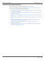
Using the Line Filter tool you can:
•
Display profiles of individual lines from a line dataset,
•
Configure and apply to the line data:
•
•
Single filters selected from a comprehensive range of standard spatial and
spectral domain filters,
•
Filters defined by you using a filter profile,
•
Filters previously defined and saved in filter definition files,
•
Composite filters consisting of a number of saved filter definitions (INTREPID
applies these serially to the data.)
View a power spectrum graph for the current filter results for any line.
Before applying the filters to the data and saving the results you can view profiles
of individual lines showing the original data and the filtered results.
•
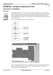
Fourier & Spatial filter Tensor, Quaternion & Vector Fields (BETA)
Using the Line Filter tool
>> To use Line Filter with the INTREPID graphic user interface
Library | Help | Top
1
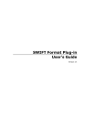
Choose Line filter from the Filter menu in the Project Manager, or use the
command lfilter.exe. INTREPID displays the Line Filter Main window.
2
If you have previously prepared file specifications and parameter settings for Line
Filter, load the corresponding task specification file using Load Options from the
File menu. (See Specifying input and output files for detailed instructions.) If all
of the specifications are correct in this file, go to step 6. If you wish to modify any
settings, carry out the following steps as required.
© 2012 Intrepid Geophysics
| Back |
INTREPID User Manual
Library | Help | Top
3
Line Filtering (T31)
2
| Back |
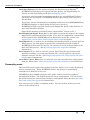
Specify the dataset for the Line Filter. Use Load Lines from the File menu. (See
Specifying input and output files for detailed instructions.)
INTREPID displays the dataset in the Line Filter window.
Library | Help | Top
4
Specify the filter you require for the dataset. See Filter operations for detailed
instructions. INTREPID displays the filter for the current line.
5
Navigate the dataset, select display options and adjust the filter specifications as
required. See Navigating the profile display, Line Filter display options and
Filter operations for detailed instructions.
6
If you wish to view filter results for some or all of the dataset, use Process from
the Line Filter window. If you wish to save the filter results into a dataset field as
well, use Save Displayed Z Trace As from the File menu instead. See Applying
the current filter and saving the filter results for detailed instructions.
7
If you wish to record the specifications for this process in a .job file in order to
repeat a similar task later or for some other reason, use Save Options from the file
menu. (See Specifying input and output files for detailed instructions.)
© 2012 Intrepid Geophysics
| Back |
INTREPID User Manual
Library | Help | Top
Line Filtering (T31)
3
| Back |
8
If you wish to repeat the process, repeat steps 4–7 (using the same dataset and Z
field) or 2–7 (using a different dataset), varying the specifications as required.
9
To exit from Line Filter, choose Quit from the File menu.
___
You can execute Line Filter as a batch task using a task specification (.job) file that
you have previously prepared. See Displaying options and using task specification
files for details.
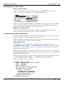
Specifying input and output files
To use Line Filter, you will need to specify the line dataset to be loaded and the Z field
to be processed. When you have specified the filter(s) to be used, you may wish to
specify a new Z field for saving the filter results.
You can also load and save filter specifications (See Loading and saving filter
definitions).
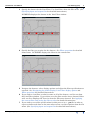
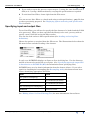
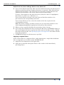
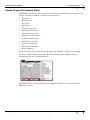
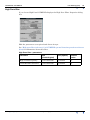
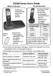
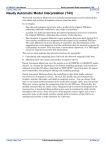
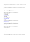
Choose the options as required from the File menu. The illustrations below show the
file menu before and after loading a line dataset.
In each case INTREPID displays an Open or Save As dialog box. Use the directory
and file selector to locate the file you require. (See "Specifying input and output files"
in Introduction to INTREPID (R02) for information about specifying files).
INTREPID may need to obtain information from the dataset aliases. If you select
spatial or chronological resampling (See Resampling mode), the dataset must have
aliases identifying appropriate field files.
Alias
Field
For spatial resampling:
X
X coordinate (location)
Y
Y coordinate (location)
For chronological resampling:
Fiducial
Fiducial count
See "Editing aliases" in Line Filtering (T31) for more information about aliases.
Library | Help | Top
© 2012 Intrepid Geophysics
| Back |
INTREPID User Manual
Library | Help | Top
Line Filtering (T31)
4
| Back |
Load Line Dataset Use this option to specify the line dataset for filtering.
INTREPID will prompt you to specify the line dataset, the Signal field to be
filtered and the resampling mode (See Resampling mode).
If you have selected spatial resampling and there are no valid X and Y aliases
specifying the location files, INTREPID displays Open dialog boxes for you to
specify them.
If you have selected chronological resampling and there is no valid Fiducial alias,
INTREPID displays an Open dialog box for you to specify it.
INTREPID will then open the dataset and display the profile of the first line in
the Line Filter Main window.
Signal field extended to include Tensors, Quaternions, Vectors at V4.1
Save Displayed Signal Trace As Use this option to specify the name for the output
Signal field containing the filter results. If you have not applied the current filter
to the required lines, INTREPID will do this before saving the results. See
Applying the current filter and saving the filter results for details.
Load Options If you wish to use an existing task specification file to specify the Line
Filter process, use this option to specify the task specification file required.
INTREPID will load the file and use its contents to set all of the parameters for
the Line Filter process. (See Specifying input and output files for more
information).
Save Options If you wish to save the current Line Filter file specifications and
parameter settings as an task specification file, use this option to specify the
filename and save the file. (See Displaying options and using task specification
files for more information).
Load Filter / Save Filter You can load and save filter specifications using options
from the Filter menu. See Loading and saving filter definitions for instructions.
Resampling mode
The Line Filter tool requires data points in the line dataset to be evenly distributed
with no internal gaps. When INTREPID loads a line dataset it immediately
resamples it so that this is the case.
INTREPID replaces nulls using the cubic spline, linear or nearest neighbour
interpolation method. The default method is linear interpolation. You can change
the method using the Current Line Statistics and Options dialog box (See Querying
lines and setting line options for instructions).
You can select one of three resampling modes. For two of these modes you need
aliases as described below.
Library | Help | Top
© 2012 Intrepid Geophysics
| Back |
INTREPID User Manual
Library | Help | Top
Line Filtering (T31)
5
| Back |
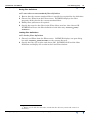
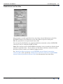
>> To select the resampling mode
1
Load a line dataset for filtering as described above. INTREPID displays the
Resampling Mode dialog box.
2
Select the resampling mode as required, then choose Accept.
Spatial ('Geo-Located') INTREPID examines the X and Y fields of the dataset and
resamples the data so that it is distributed evenly with respect to distance. If you
choose this option your line dataset must have properly defined X and Y aliases.
Chronological ('Time-Based') INTREPID examines the fiducial field of the dataset
and resamples the data so that it is distributed evenly with respect to time. If you
choose this option your line dataset must have a properly defined Fiducial alias.
Unlocated ('Fixed Increment)' INTREPID ignores any X Y and Fiducial data and
assumes that the data points are already evenly distributed. You can then specify
a resampling interval for the data, using some or all of it in the Line Filter
process.
Resampling interval ('Sample Increment') Use this text box to specify the
resampling interval for Unlocated resampling mode. INTREPID will use this to
select data points for the line filtering process. For example:
If you specify a resampling interval of 2, INTREPID will use every second data
point for calculating the line filters.
If you specify a resampling interval of .5, INTREPID will include an interpolated
data point between each pair of the original points for calculating the line filters.
Editing aliases
While using the Resampling Mode dialog box you can edit the dataset aliases. You
may wish to do this in order to specify an X, Y or Fiducial alias for use in this tool.
See "Vector dataset field aliases" in INTREPID database, file and data structures
(R05) for more information about aliases.
Library | Help | Top
© 2012 Intrepid Geophysics
| Back |
INTREPID User Manual
Library | Help | Top
Line Filtering (T31)
6
| Back |
>> To edit aliases
1
Choose Edit Dataset Aliases from the Resampling Mode dialog box.
2
INTREPID may display an Open dialog box for a vector dataset. If it does, select
the current dataset.
3
INTREPID displays the Dataset Alias Editor.
This editor works in the same way as the one displayed by the Project Manager. See
"Editing the dataset aliases" in INTREPID Old Project Manager (T01) for
instructions.
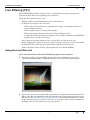
Navigating the profile display
The Line Filter window shows two profiles of a single line from the dataset (the
current line). These profiles are
•
The original Z field and
•
The results of filters currently specified.
Normally the horizontal scales of the Z field and filter results are synchronised, so
that you can compare corresponding values for any data point.
Library | Help | Top
© 2012 Intrepid Geophysics
| Back |
INTREPID User Manual
Library | Help | Top
Line Filtering (T31)
7
| Back |
You can navigate the dataset display in the following ways.
•
Viewing the profile of any line in the dataset;
•
Zooming in on any section of a profile.
Selecting a line you wish to view
When you first load a line dataset, INTREPID displays Z data from the first line in
the dataset. You can display other lines using the Next, Previous and Go To
command buttons.
The Line Filter automatically sorts line numbers into ascending order, no irrespective
of their actual order in the dataset.
>> To view the Next or Previous line (according to line number)
Use Next or Previous from the Line Filter window to view the next or previous line
respectively.
>> To view the line of your choice
1
Choose Go To in the Line Filter window. INTREPID displays the Select Line
dialog box.
2
Select (click) the number of the line you wish to view, then choose OK.
INTREPID displays the line.
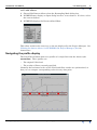
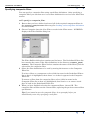
Enlarging and reducing (zooming) the profile display
You can enlarge the profile display (zoom in) to display only part of a line profile, then
zoom out again when you have finished.
You can specify whether both profiles will remain synchronised when you perform
zoom operations. Normally INTREPID synchronises the profiles. See Querying lines
and setting line options for instructions about turning synchronisation on and off.
Library | Help | Top
© 2012 Intrepid Geophysics
| Back |
INTREPID User Manual
Library | Help | Top
Line Filtering (T31)
8
| Back |
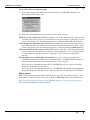
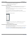
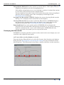
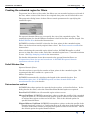
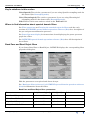
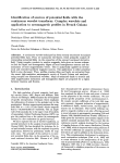
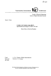
>> To zoom in on a set of data points
1
Move the mouse pointer to one corner of the region that you wish to enlarge. Hold
down the left button and drag to the diagonally opposite corner of the region.
INTREPID displays a frame defining the region you select.
2
Release the mouse button.
INTREPID will enlarge the display to show only those points you selected.
In this illustration the INTREPID has not synchronised the profiles.
>> To zoom out
Double click anywhere in the zoomed display with the left mouse button.
Library | Help | Top
© 2012 Intrepid Geophysics
| Back |
INTREPID User Manual
Library | Help | Top
Line Filtering (T31)
9
| Back |
Line Filter display options
Querying lines and setting line options
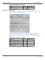
You can display information about the current line and select a range of options for
processing it, as described in this section.
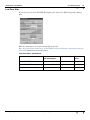
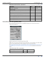
>> To query the current line and select options
1
Right button click the line display. INTREPID displays the Current Line
Statistics and Options dialog box. Note this is a Tensor example display
2
View the statistics and select options as required, then choose Accept.
No of Samples The number of data points in the current line that have values for
the current Z field.
No of Interpolated Samples The number of data points in the current line derived
by resampling and used for the line filter calculations.
Maximum Z Value, Minimum Z Value, Mean Z Value, Z Values Standard
Deviation INTREPID displays basic statistics for the current line
Sample Spacing (Spatial resampling only) This parameter corresponds to the
distance between interpolated samples. You can modify this to increase or
decrease the resampling rate and thus the Nyquist frequency16.
Nyquist Frequency The highest frequency possible in the spectral domain given the
current resampling rate13.
1.6 In the current version of INTREPID, this statistic is provided by a revised general
reporting class. See Resampling mode for further details.
Library | Help | Top
© 2012 Intrepid Geophysics
| Back |
INTREPID User Manual
Library | Help | Top
Line Filtering (T31)
10
| Back |
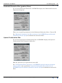
Interpolation Method Use these options to specify Linear, Cubic Spline, Nearest
Neighbour interpolation for the resampling process.
Cubic Spline interpolation uses a curve through a number of original data points
on each side of the position for the resampled point.
Nearest neighbour uses the Z value of the nearest data point if the resampling is
spatial or the preceding Z value if the resampling is chronological (See
Resampling mode for details).
Average Line Direction INTREPID displays the average bearing (North towards
the top as in a compass) of the current line in this diagram.
Overlay Filtered Line If you turn on Overlay Filtered Line, INTREPID displays
the filter results in white both in their own display area and overlaid on the
original Z data profile (See Overlaying the filter results for details).
Zoom both lines If you turn on this option, INTREPID will synchronise the
horizontal axes of both profiles during zoom operations, so you will be zooming on
both lines simultaneously. If you turn off this option, INTREPID will only
enlarge and reduce the profile you use to specify the zoom.
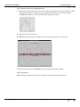
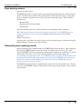
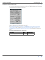
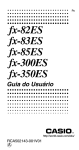
Overlaying the filter results
INTREPID can display the filter results in white both in their own display area and
overlaid on the original Z data profile.
>> To turn filter overlay display on or off
Turn the Overlay Filtered Line on or off in the Current Line Statistics and Options
dialog box (See Querying lines and setting line options for more information about
this dialog box). The illustration below shows a profile with filter overlay turned on.
Library | Help | Top
© 2012 Intrepid Geophysics
| Back |
INTREPID User Manual
Library | Help | Top
Line Filtering (T31)
11
| Back |
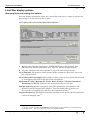
Power Spectrum display
If the current filter is a spectral domain filter, you can display a power spectrum
graph of the filter results for the current line. The vertical axis represents energy
(spectral power). The horizontal axis represents frequency in:
•
Cycles/km if you have used spatial resampling to prepare the data for the Line
Filter.
•
Hertz if you have used chronological sampling to prepare the data for the Line
Filter.
See Resampling mode for information about spatial vs chronological resampling.
>> To display the spectral domain Power Spectrum graph for the current line
(when using spectral domain filters only)
1
Ensure that the current filter is a spectral domain filter.
2
Choose Power Spectrum from the Line Filter main window. INTREPID displays
the graph in a separate window.
Choose Accept to close the window when you have finished viewing it.
For further information about power spectrum graphs see "Power spectrum
graphs" in INTREPID spectral domain operations reference (R14).
Library | Help | Top
© 2012 Intrepid Geophysics
| Back |
INTREPID User Manual
Library | Help | Top
Line Filtering (T31)
12
| Back |
Filter operations
Overview
You can perform the following operations with filters for the current dataset and Z
field:
•
Specify a new filter which can be
•
One of the standard filters supplied with INTREPID,
•
A filter specified by you using a profile with control points,
•
A composite filter consisting of two or more standard and/or user defined
filters;
•
Load a filter definition file in order to specify a new filter;
•
View and modify if required the current filter parameters;
•
View and edit if required the user defined filter if it exists;
•
Save the current filter definition to a filter definition file for later reference or use;
•
View the Power Spectrum graph for the current filter;
•
Overlay the current filter profile on the original Z field profile;
•
Apply the filter to the dataset and save the results in a Z field if required.
You can perform all but three of these operations using options from the Filter menu.
For viewing the power spectrum graph see Power Spectrum display.
For overlaying the display, see Overlaying the filter results.
For applying the filter and saving the results see Applying the current filter and
saving the filter results.
Some filter concepts
Filter windows Many of the processes performed on a line involve a 'window'. In
order to process a target data point (e.g, calculate a new value for it), INTREPID
examines a number of data points on either side of it. The set of points involved in
the process including the target point is called a window. In most cases
INTREPID processes a set of adjacent data points and often the whole line. It will
create a different window for each data point based on the neighbouring points.
In this way INTREPID 'passes a window across' the data.
No of Weight Control Points When user defined filters are available in
INTREPID, their profile will be defined in terms of a number of coefficients
corresponding to weigh control points in the profile. Contact our technical support
service for information about this topic if required.
INTREPID spatial and time domain filters and transformations
For full details of spatial and time domain filters provided with INTREPID, see
INTREPID spatial and time domain filters and transformations (R13).
INTREPID spectral domain operations
For full details of spectral domain operations and the spectral domain filters provided
with INTREPID, see INTREPID spectral domain operations reference (R14).
The Line Filter tool actually uses the Hartley algorithm for the spectral transform.
'Fourier' is used in this chapter in a 'generic' sense.
Library | Help | Top
© 2012 Intrepid Geophysics
| Back |
INTREPID User Manual
Library | Help | Top
Line Filtering (T31)
13
| Back |
Specifying a new filter
When you specify a new filter, it will replace the existing filter specification. You can
create composite filters using saved filter definitions. See Specifying composite filters
for instructions.
Specifying standard filters
New standard filters
>> To specify a standard filter
1
Ensure that you have saved any existing filter definition as required (See
Loading and saving filter definitions for instructions).
2
Choose the filter you require from the Standard cascade from New Filter in the
Filter menu. INTREPID displays the corresponding to the filter properties dialog
box.
3
Specify filter properties as required, then choose Accept. INTREPID displays the
filter as specified for the current line and be ready to apply it to the dataset as
required.
Viewing and modifying the current standard filter properties
>> To view and modify if required the current standard filter properties
1
Choose Current Filter Properties from the Filters menu.
OR
Right button click the Filtered Line Display profile.
INTREPID displays the properties dialog box for the current standard filter. See
Standard Spatial Domain filters and Standard spectral domain filters for details
of the filter properties.
2
View and modify if required the filter properties, then choose Accept.
Standard filter names
Each standard filter properties dialog box contains a Filter Name text box. When you
first specify a new filter it shows the type of filter with the notation Untitled.
If you save the current settings for the current standard filter, you specify the name
of the saved filter specifications in the Filter Name text box. INTREPID uses this file
name when storing it. See Loading and saving filter definitions for details.
If you load an existing set of standard filter specifications, INTREPID will identify it
using the name in the text box. See Loading and saving filter definitions for details.
Library | Help | Top
© 2012 Intrepid Geophysics
| Back |
INTREPID User Manual
Library | Help | Top
Line Filtering (T31)
14
| Back |
Specifying user defined filters
New user defined filters
The user defined filters facility will be available in INTREPID shortly. Please
contact our technical support service for further information.
Choose Fourier or Spatial from the User Defined cascade in New Filter in the Filter
menu. (The Line Filter tool actually uses the Hartley algorithm for the spectral
transform. 'Fourier' is used here in a 'generic' sense.)
Editing a user defined filter
The user defined filters facility will be available in INTREPID shortly. Please
contact our technical support service for further information.
Loading and saving filter definitions
You can save filter definitions for use at a later time, and maintain your own library
of filter definitions for loading into the Line Filter tool.
Before specifying a composite filter you must save the definitions of the component
filters. See Specifying composite filters for details.
Filter definition files
INTREPID stores filter definitions as block-structured auxiliary files with
FilterDescription Begin – FilterDescription End blocks. See "INTREPID
Auxiliary files" in INTREPID database, file and data structures (R05) for general
details about auxiliary files.
Filter definition files have the extension .fdf and normally reside in the directory
install_path/filters. Filter definitions to be used in creating a composite filter
must reside in this directory.
A filter definition file may contain a number of filter definitions. Each will have its
own FilterDescription Begin – FilterDescription End block.
Here is a sample filter definition file.
FilterDescription Begin
Name = UpwardContinuation-Survey67
Space = FOURIER
Type = INTRINSIC
IntrinsicType = UPCONTINUATION
UpwardContinuation Begin
Level = 100.000000
DataWindowType = HANNING
DataPadType = MIRROR_PAD
RolloffWindowSize = 16
UpwardContinuation End
FilterDescription End
Library | Help | Top
© 2012 Intrepid Geophysics
| Back |
INTREPID User Manual
Library | Help | Top
Line Filtering (T31)
15
| Back |
Saving filter definitions
>> To save the current standard filter definition
1
Ensure that the current standard filter is specified as required for the definition.
2
Choose Save Filter from the Filters menu. INTREPID displays the filter
properties dialog box for the current standard filter.
3
Modify filter parameters if required.
4
Specify the name for the filter in the Filter Name text box, then choose OK.
INTREPID will save the filter definition in the directory install_path/
filters17.
Loading filter definitions
>> To load a filter definition
1
Choose Load Filter from the Filters menu. INTREPID displays an open dialog
box with install_path/filters as the current directory.
2
Specify the filter you require and choose OK. INTREPID will load the filter
definition and display the results in the Line Filter window.
1.7 Before you do this the first time, check that the directory exists and create it if
necessary.
Library | Help | Top
© 2012 Intrepid Geophysics
| Back |
INTREPID User Manual
Library | Help | Top
Line Filtering (T31)
16
| Back |
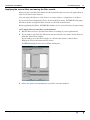
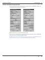
Specifying composite filters
You can specify a composite filter using saved filter definitions. After specifying a
composite filter you can then save it as a filter definition for use in a later Line Filter
session.
>> To specify a composite filter
1
Ensure that you have defined and saved all of the required component filters in
the install_path/filters directory (See Loading and saving filter definitions
for instructions).
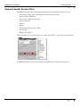
2
Choose Composite from the New Filter cascade in the Filter menu. INTREPID
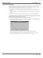
displays the Filter Builder dialog box.
The Filter Builder dialog box contains two list boxes. The Predefined Filters list
box contains the names of the filter definitions in the directory install_path/
filters. The Composite Filter list box contains the names of the filters you have
selected for the composite filter.
3
Select the filter definitions to be used by moving their names to the Composite
Filter list.
To select a filter as a component, select (click) its name in the Predefined Filters
list so that it is highlighted, then choose >> so that it appears in the Composite
Filter list.
To remove a filter from the composite filter, select (click) its name in the
Composite Filter list so that it is highlighted, then choose << to remove it and
place it back in the Predefined Filters list.
4
When you have finished selecting the component filters, choose OK. The
composite filter will become the current filter, replacing the previous current filter
specification.
Tip: If you intend to save the composite filter, do so promptly before you
inadvertently erase it by specifying a new filter.
Library | Help | Top
© 2012 Intrepid Geophysics
| Back |
INTREPID User Manual
Library | Help | Top
Line Filtering (T31)
17
| Back |
Applying the current filter and saving the filter results
After you have specified the filters for the Line Filter process you can apply them to
some or all lines in the dataset.
You can apply the filter to a list of lines, a range of lines, a single line or all lines.
If you choose Save Displayed Z Trace As from the File menu, INTREPID will apply
the filters before saving the filter results as a Z field in the dataset.
Before applying the filters, INTREPID enables you to select the lines for processing.
>> To apply the current filter to the dataset
1
Ensure that you have specified the filters according to your requirements.
2
If you wish to calculate the filters but not necessarily save them, choose Process
from the Line Filter window.
If you wish to save the filter results as a field of the dataset, choose Save
Displayed Z Trace As from the File menu.
INTREPID displays the Lines to Filter dialog box.
3
Library | Help | Top
Select the option corresponding to your line selection method.
© 2012 Intrepid Geophysics
| Back |
INTREPID User Manual
Library | Help | Top
Line Filtering (T31)
18
| Back |
Select from List, Select a Range, Select a Line, Select All
4
If you selected Select from List, Move the line numbers between the Dataset Line
Numbers and Selected Line Numbers list boxes as required. (The Selected Line
Numbers list box shows a list of the lines for processing and the Dataset Line
Numbers list box shows a list of lines that are not for processing.)
To move a line number to the other list select (click) it so that it is highlighted,
then choose >> Add >> or << Remove <<.
If you selected Select a Range, enter the first and last line numbers to be
processed into the corresponding text boxes.
If you selected Select a Line, enter the number of the line required in the
corresponding text box.
Note: For Select a Range and Select a Line you can enter line numbers or the
words start and end which signify the first and last line numbers.
5
When you have specified the lines for processing, choose Accept.
6
If you chose Save Displayed Z Trace As from the File menu, INTREPID displays a
Save As dialog box for you to specify the field name for the filter results. Specify
the field and choose OK. See Specifying input and output files for further details
about file operations.
7
INTREPID will process the dataset as specified.
Applying composite filters
If the current filter is a composite filter, either loaded from a single filter definition
file or composed by you in this session, INTREPID will
Library | Help | Top
1
Apply the first component to the input data;
2
Apply the second and subsequent filters to the results of the immediately
preceding filters.
© 2012 Intrepid Geophysics
| Back |
INTREPID User Manual
Library | Help | Top
Line Filtering (T31)
19
| Back |
Creating the extended region for filters
To prevent loss of data at line ends, line filters use an extended region at each end of
the line, where values of the first or last original data point can be rolled off to zero.
The properties dialog boxes of these filters contain parameters for specifying the
extended region.
For spectral domain filters you can specify the size of the extended region. The
extended region size for the Hilbert transform is half of the filter window length. See
Rolloff Window Size for detailed instructions.
INTREPID calculates initial Z values for the data points in the extended region.
These can be based on nearby original data values. See Data extension method for
instructions.
After calculating the extended region initial values, INTREPID applies a rolloff
process so that the values at the end of the extended region have a smooth transition
to zero. See Edge damping methods for instructions.
For further information about data extension for spectral domain filters see
"Preparation of data for spectral transform" in INTREPID spectral domain
operations reference (R14).
Rolloff Window Size
Spectral domain filters:
Use the text box to specify the number of data points in the extended region. We
recommend that this number is a power of 2.
Hilbert Transform:
INTREPID automatically calculates the length of the extended region. See
"Extended region size" in INTREPID spatial and time domain filters and
transformations (R13) for details.
Data extension method
INTREPID has three options for extended region values, as described below. In the
dialog box for the filter, select the Data Extension Method option as required.
Zero Pad INTREPID sets all extended region values to zero.
Mirror Pad Data INTREPID extrapolates values so that the profile of the extended
region Z values is a Y reflection of the profile of the Z values of the same number
of original data points at that end of the line. This is the default option for
spectral domain filters.
Flipped Mirror Pad Data INTREPID extrapolates values so that the profile of the
extended region Z values is a Y reflection then an X reflection of the profile of the
Z values of the same number of original data points at that end of the line. This is
the default option for spatial domain filters.
Library | Help | Top
© 2012 Intrepid Geophysics
| Back |
INTREPID User Manual
Library | Help | Top
Line Filtering (T31)
20
| Back |
Edge damping methods
Spectral domain filters:
INTREPID provides a choice of three edge damping methods for the extended region
values. Each of these modifies the initial values of the extended region so that they
have a smooth transition to zero at the end of the extended region. The available
methods are
•
Bartlett filter
•
Hanning (the default method)
•
Parzen filter
The filter dialog boxes have option buttons corresponding to these methods.
See "Damping of dataset edges before spectral transform" in INTREPID spectral
domain operations reference (R14) for further information about these rolloff
methods.
Hilbert Transform:
automatically calculates the rolloff values in the extended region, normally using the
Flipped Mirror Pad data extension method.
Detrending and replacing trends
Before applying most standard filters, INTREPID detrends the data. After applying
the filter, INTREPID will replace the trend if it makes sense to do so. For some
filters INTREPID includes an option in the properties dialog box enabling you to turn
trend replacement on or off. For further information about detrending, see
"Detrending and replacing trends" in INTREPID spatial and time domain filters and
transformations (R13) and "Detrending data values" in INTREPID spectral domain
operations reference (R14) and "Reproducing the trend" in INTREPID spectral
domain operations reference (R14).
INTREPID detrends using a weighted least squares fit on a line by line basis. Future
releases of INTREPID will have the option of removing a single dataset average trend
from all lines.
Library | Help | Top
© 2012 Intrepid Geophysics
| Back |
INTREPID User Manual
Library | Help | Top
Line Filtering (T31)
21
| Back |
Standard Spatial Domain filters
INTREPID includes the following spatial domain standard filters for your use:
•
Convolution filter with user defined kernel (available soon)
•
Local median (Median)
•
Local mean (Moving Average)
•
Local maximum
•
Naudy
•
Fuller
•
Automatic Gain Control (AGC)
•
Lacoste RC
•
Hilbert Transform
Select the filter you want from the list under the Spatial....New Convolution option.
INTREPID displays the corresponding standard filter properties dialog box.
Library | Help | Top
© 2012 Intrepid Geophysics
| Back |
INTREPID User Manual
Library | Help | Top
Line Filtering (T31)
22
| Back |
Information about spatial domain filters
The Line Filter tool uses the standard dialog box for each filter.
See the corresponding sections in INTREPID spatial and time domain filters and
transformations (R13) for details about the filters:
Library | Help | Top
•
"User defined convolution kernels" in INTREPID spatial and time domain filters
and transformations (R13),
•
"Local mean / median filters" in INTREPID spatial and time domain filters and
transformations (R13),
•
"Fuller filter" in INTREPID spatial and time domain filters and transformations
(R13),
•
"Naudy filter" in INTREPID spatial and time domain filters and transformations
(R13),
•
"Automatic gain control filter for line data" in INTREPID spatial and time
domain filters and transformations (R13),
•
"Hilbert transform" in INTREPID spatial and time domain filters and
transformations (R13),
•
"Phillips automatic depth estimation" in INTREPID spatial and time domain
filters and transformations (R13).
© 2012 Intrepid Geophysics
| Back |
INTREPID User Manual
Library | Help | Top
Line Filtering (T31)
23
| Back |
Standard spectral domain filters
INTREPID includes the following spectral domain standard filters for your use. You
can use the filters marked * with full tensor datasets.
•
Band Pass*
•
Band Reject*
•
Low Pass*
•
High Pass*
•
Vertical Derivative
•
Horizontal Derivative
•
Upward Continuation
•
Downward Continuation
•
Variable Continuation
•
Reduction to the Pole
•
Vertical Component
•
Horizontal Component
•
Fourier Hilbert
Select the filter you want from the list under the Spectral....New Fourier option.
For more complex signal fields, just Band Pass/Reject, Low & High pass are
supported in the V4.1 implementation
INTREPID displays the standard filter properties dialog box as described in the
following sections.
Library | Help | Top
© 2012 Intrepid Geophysics
| Back |
INTREPID User Manual
Library | Help | Top
Line Filtering (T31)
24
| Back |
Key to notations in this section
Unit (Spatial) The unit for a parameter if you are using Spatial resampling mode for
the dataset (See Resampling mode).
Unit (Chronological) The unit for a parameter if you are using Chronological
resampling mode for the dataset (See Resampling mode).
Fids Fiducial clock count units as stored in the Fiducial field.
Where to find information about spectral domain filters
See Filter operations and Creating the extended region for filters and the early
sections of INTREPID spectral domain operations reference (R14) for a description of
the pre and post transformation processes.
See Power Spectrum display for instructions about displaying the power spectrum
graph for a filter.
See INTREPID spectral domain operations reference (R14) for a full description of
these filters.
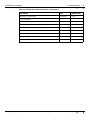
Band Pass and Band Reject filters
If you choose Band Pass or Band Reject, INTREPID displays the corresponding filter
properties dialog box.
Edit the parameters as required and choose Accept.
See "Band pass filter (reference)" in INTREPID spectral domain operations reference
(R14) for information about this filter.
Band Pass and Band Reject filter—parameters
Parameter
Unit (Chronological)
Unit (Spatial)
Default value
Low Cutoff Frequency
cycles/1000 fids
cycles/km
10
(Low) Cutoff Rolloff Parameter
cycles/1000 fids
cycles/km
5
High Cutoff Frequency
cycles/1000 fids
cycles/km
25
(High) Cutoff Rolloff Parameter
cycles/1000 fids
cycles/km
5
Library | Help | Top
© 2012 Intrepid Geophysics
| Back |
INTREPID User Manual
Library | Help | Top
Line Filtering (T31)
25
| Back |
Low Pass filter
If you choose Low Pass INTREPID displays the Low Pass Filter Properties dialog
box.
Edit the parameters as required and choose Accept.
See "Low pass filter (reference)" in INTREPID spectral domain operations reference
(R14) for information about this filter.
Low Pass filter—parameters
Parameter
Unit
(Chronological)
Unit (Spatial)
Default
value
Low Cutoff Frequency
cycles/1000 fids
cycles/km
25
Cutoff Rolloff Parameter
cycles/1000 fids
cycles/km
5
Replace trend in output
Library | Help | Top
© 2012 Intrepid Geophysics
Yes
| Back |
INTREPID User Manual
Library | Help | Top
Line Filtering (T31)
26
| Back |
High Pass filter
If you choose High Pass INTREPID displays the High Pass Filter Properties dialog
box.
Edit the parameters as required and choose Accept.
See "High pass filter (reference)" in INTREPID spectral domain operations reference
(R14) for information about this filter.
High Pass filter—parameters
Library | Help | Top
Parameter
Unit
(Chronological)
Unit (Spatial)
Default
value
High Cutoff Frequency
cycles/1000 fids
cycles/km
5
Cutoff Rolloff Parameter
cycles/1000 fids
cycles/km
5
© 2012 Intrepid Geophysics
| Back |
INTREPID User Manual
Library | Help | Top
Line Filtering (T31)
27
| Back |
Reduction to the Pole filter
(North–South oriented acquisition lines only) If you choose Reduction to the Pole,
INTREPID displays the Reduction to the Pole Filter Properties dialog box.
Edit the parameters as required and choose OK.
You can specify the Earth's core magnetic field data manually or have INTREPID
calculate it for you using the AGRF or IGRF.
Note: The current version of INTREPID will produce correct results for North–South
oriented acquisition lines. If you wish to use this filter with lines oriented in other
directions, please contact our technical support service.
See "Reduction filters (reference)" in INTREPID spectral domain operations
reference (R14) and, specifically, "Reduction to the Pole (reference)" in INTREPID
spectral domain operations reference (R14) for information about this filter.
Library | Help | Top
© 2012 Intrepid Geophysics
| Back |
INTREPID User Manual
Library | Help | Top
Line Filtering (T31)
28
| Back |
Reduction to the Pole filter—parameters
Parameter
Unit
Default value
Reference Field Date
dd mm yy
1 1 80
Sensor height
m
0
Calculate Latitude and Longitude from line data?
Yes
Latitude
°
0
Longitude
°
0
Reference Field (AGRF / IGRF / Manual)
AGRF
(Manual) Field Strength
Z units
0
(Manual) Field Declination
°
0
(Manual) Field Inclination
°
0
Vertical Derivative filter (gradient filters)
If you choose Vertical Derivative, INTREPID displays the Vertical Derivative
Properties dialog box.
Edit the parameters as required and choose OK.
Note: You can specify a fractional vertical derivative. For example, if you have noisy
data you may obtain better results using the 0.85 vertical derivative.
See "Vertical derivative filter (including fractional vertical derivative) (reference)" in
INTREPID spectral domain operations reference (R14) for information about this
filter.
Vertical Derivative filter—parameters
Parameter
Unit
Order of Differentiation
Library | Help | Top
© 2012 Intrepid Geophysics
Default value
1
| Back |
INTREPID User Manual
Library | Help | Top
Line Filtering (T31)
29
| Back |
Horizontal Derivative filter (gradient filters)
If you choose Horizontal Derivative, INTREPID displays the Horizontal Derivative
Properties dialog box.
There are no specific parameters for the Horizontal Derivative filter. Choose OK.
See "Horizontal derivative line filter (reference)" in INTREPID spectral domain
operations reference (R14) for information about this filter.
Upward Continuation filter
If you choose the Upward Continuation filter, INTREPID displays the Upward
Continuation Filter Properties dialog box.
Edit the parameter as required and choose OK.
See "Continuation filters (reference)" in INTREPID spectral domain operations
reference (R14) and, specifically "Upward Continuation filter (reference)" in
INTREPID spectral domain operations reference (R14) for information about this
filter.
Library | Help | Top
© 2012 Intrepid Geophysics
| Back |
INTREPID User Manual
Library | Help | Top
Line Filtering (T31)
30
| Back |
Upward Continuation filter—parameters
Parameter
Unit
Default value
Level of Continuation
m
100
Variable continuation filter
If you choose the Variable Continuation filter, INTREPID displays the Variable
Continuation Filter Properties dialog box.
See "Continuation filters (reference)" in INTREPID spectral domain operations
reference (R14) and, specifically "Variable continuation filter (reference)" in
INTREPID spectral domain operations reference (R14) for information about this
filter.
Variable continuation filter—parameters
Parameter
Unit
Nominal Level of Survey
m
Default value
Number of Bins to Sort Heights
Nominal Height of Bin
m
Cutoff Weight
Library | Help | Top
© 2012 Intrepid Geophysics
| Back |
INTREPID User Manual
Library | Help | Top
Line Filtering (T31)
31
| Back |
Downward Continuation filter
If you choose the Downward Continuation filter, INTREPID displays the Downward
Continuation Filter Properties dialog box.
Edit the parameter as required and choose OK.
See "Continuation filters (reference)" in INTREPID spectral domain operations
reference (R14) and, specifically "Downward Continuation filter (reference)" in
INTREPID spectral domain operations reference (R14) for information about this
filter.
Downward Continuation filter—Parameters
Library | Help | Top
Parameter
Unit
Default value
Level of Continuation
m
100
© 2012 Intrepid Geophysics
| Back |
INTREPID User Manual
Library | Help | Top
Line Filtering (T31)
32
| Back |
Vertical / Horizontal Component filter
If you choose the Vertical or Horizontal Component filter, INTREPID displays the
corresponding filter properties dialog box.
Edit the parameters as required and choose OK.
You can specify the Earth's core magnetic field data manually or have INTREPID
calculate it for you using the AGRF or IGRF.
See "Horizontal and vertical components filters (reference)" in INTREPID spectral
domain operations reference (R14) for information about this filter.
Library | Help | Top
© 2012 Intrepid Geophysics
| Back |
INTREPID User Manual
Library | Help | Top
Line Filtering (T31)
33
| Back |
Vertical / Horizontal Component filter—Parameters
Parameter
Unit
Default value
Reference Field Date
dd mm yy
1 1 80
Sensor height
m
0
Calculate Latitude and Longitude from line data?
Yes
Latitude
°
0
Longitude
°
0
Reference Field (AGRF / IGRF / Manual)
Library | Help | Top
AGRF
(Manual) Field Strength
Z units (nT)
0
(Manual) Field Declination
°
0
(Manual) Field Inclination
°
0
© 2012 Intrepid Geophysics
| Back |
INTREPID User Manual
Library | Help | Top
Line Filtering (T31)
34
| Back |
Special filters
INTREPID includes the following special purpose filters for your use:
•
Phillips Depth
•
Gravity Inversion
•
Strip Gravity Layer
•
Pass through
Select the filter you want from the list under the Special....New Special option.
Phillips Depth filter
If you choose the Phillips Depth filter, INTREPID displays the Phillips Auto Depth
Filter Properties dialog box.
Edit the parameters as required and choose OK
See "Phillips automatic depth estimation" in INTREPID spatial and time domain
filters and transformations (R13).
Gravity Inversion filter
If you choose the Gravity Inversion filter, INTREPID displays the Gravity Inversion
Filter Properties dialog box.
Edit the parameters as required and choose OK
See "Phillips automatic depth estimation" in INTREPID spatial and time domain
filters and transformations (R13).
Exit
To exit from Line Filter choose Quit from the file menu.
Library | Help | Top
© 2012 Intrepid Geophysics
| Back |
INTREPID User Manual
Library | Help | Top
Line Filtering (T31)
35
| Back |
Displaying options and using task specification files
Displaying options
See Querying lines and setting line options for information about displaying the prefilter settings for the current line.
See Viewing and modifying the current standard filter properties for information
about displaying the filter settings.
Using task specification files
You can store sets of file specifications and parameter settings for Line Filter in task
specification (.job) files.
>> To create a task specification file with the Line Filter tool
1
Specify all files and parameters.
2
If possible, execute the task (choose Apply) to ensure that it will work.
3
Choose Save Options from the File menu. Specify a task specification file
(INTREPID will add the extension .job) INTREPID will create the file with the
settings current at the time of the Save Options operation.
For full instructions on creating and editing task specification files see INTREPID
task specification (.job) files (R06).
>> To use a task specification file for a batch mode Line Filter task
Type the command nlinefilter.exe with the switch –batch followed by the name
(and path if necessary) of the task specification file.
For example, if you had a task specification file called surv329.job in the current
directory you would use the command
nlinefilter.exe –batch surv329.job
Library | Help | Top
© 2012 Intrepid Geophysics
| Back |
INTREPID User Manual
Library | Help | Top
Line Filtering (T31)
36
| Back |
Task specification file notes and example
Here is an example of a Line Filter task specification file.
Process Begin
Name = linefilter
Parameters Begin
InputFilters Begin
InputFilter = "UpwardContinuation-Untitled"
InputFilters End
LineIO Begin
InputLines = "/disk1/survey67/ebagoola_S"
InputZField = "/disk1/survey67/ebagoola_S/raw_mag"
OutputZField = "/disk1/survey67/ebagoola_S/upward"
LineIO End
ProcessParameters Begin
Process = "ALL_LINES"
StartLineNumber = 2731
EndLineNumber = 7122
NoOfLines = 36
SampleMode = "XY_BASED"
ProcessParameters End
Parameters End
Process End
Library | Help | Top
© 2012 Intrepid Geophysics
| Back |